EP3587357A1 - System zur behandlung von wasser mittels druckentspannungsflotation und filtrationsmembranen - Google Patents
System zur behandlung von wasser mittels druckentspannungsflotation und filtrationsmembranen Download PDFInfo
- Publication number
- EP3587357A1 EP3587357A1 EP18382464.8A EP18382464A EP3587357A1 EP 3587357 A1 EP3587357 A1 EP 3587357A1 EP 18382464 A EP18382464 A EP 18382464A EP 3587357 A1 EP3587357 A1 EP 3587357A1
- Authority
- EP
- European Patent Office
- Prior art keywords
- membranes
- tank
- flotation
- water
- area
- Prior art date
- Legal status (The legal status is an assumption and is not a legal conclusion. Google has not performed a legal analysis and makes no representation as to the accuracy of the status listed.)
- Withdrawn
Links
- 239000012528 membrane Substances 0.000 title claims abstract description 29
- XLYOFNOQVPJJNP-UHFFFAOYSA-N water Substances O XLYOFNOQVPJJNP-UHFFFAOYSA-N 0.000 title claims abstract description 22
- 238000001914 filtration Methods 0.000 title claims abstract description 18
- 238000009300 dissolved air flotation Methods 0.000 title claims abstract description 16
- 238000005188 flotation Methods 0.000 claims abstract description 12
- 238000013019 agitation Methods 0.000 claims abstract description 4
- 239000010802 sludge Substances 0.000 claims description 16
- 238000000108 ultra-filtration Methods 0.000 claims description 8
- 238000010926 purge Methods 0.000 claims description 3
- 238000004220 aggregation Methods 0.000 abstract description 5
- 230000002776 aggregation Effects 0.000 abstract description 5
- 238000004140 cleaning Methods 0.000 abstract description 4
- 239000002245 particle Substances 0.000 description 6
- 239000010410 layer Substances 0.000 description 5
- 238000000926 separation method Methods 0.000 description 5
- 238000000034 method Methods 0.000 description 3
- 239000007787 solid Substances 0.000 description 3
- 238000012423 maintenance Methods 0.000 description 2
- 238000005273 aeration Methods 0.000 description 1
- 238000005345 coagulation Methods 0.000 description 1
- 230000015271 coagulation Effects 0.000 description 1
- 230000000295 complement effect Effects 0.000 description 1
- 239000000356 contaminant Substances 0.000 description 1
- 238000005189 flocculation Methods 0.000 description 1
- 230000002706 hydrostatic effect Effects 0.000 description 1
- 239000007788 liquid Substances 0.000 description 1
- 238000005374 membrane filtration Methods 0.000 description 1
- 239000000203 mixture Substances 0.000 description 1
- 230000000717 retained effect Effects 0.000 description 1
- 229920006395 saturated elastomer Polymers 0.000 description 1
- 238000000638 solvent extraction Methods 0.000 description 1
- 239000002344 surface layer Substances 0.000 description 1
- 239000000725 suspension Substances 0.000 description 1
Images


Classifications
-
- C—CHEMISTRY; METALLURGY
- C02—TREATMENT OF WATER, WASTE WATER, SEWAGE, OR SLUDGE
- C02F—TREATMENT OF WATER, WASTE WATER, SEWAGE, OR SLUDGE
- C02F1/00—Treatment of water, waste water, or sewage
- C02F1/24—Treatment of water, waste water, or sewage by flotation
-
- C—CHEMISTRY; METALLURGY
- C02—TREATMENT OF WATER, WASTE WATER, SEWAGE, OR SLUDGE
- C02F—TREATMENT OF WATER, WASTE WATER, SEWAGE, OR SLUDGE
- C02F1/00—Treatment of water, waste water, or sewage
- C02F1/44—Treatment of water, waste water, or sewage by dialysis, osmosis or reverse osmosis
- C02F1/444—Treatment of water, waste water, or sewage by dialysis, osmosis or reverse osmosis by ultrafiltration or microfiltration
-
- C—CHEMISTRY; METALLURGY
- C02—TREATMENT OF WATER, WASTE WATER, SEWAGE, OR SLUDGE
- C02F—TREATMENT OF WATER, WASTE WATER, SEWAGE, OR SLUDGE
- C02F2303/00—Specific treatment goals
- C02F2303/16—Regeneration of sorbents, filters
Definitions
- the invention belongs to the water treatment sector, particularly to dissolved air flotation and membrane systems.
- a dissolved air flotation (DAF) system is a system responsible for removing particles suspended in contaminated water by means of air microbubbles. Solids adhere to the microbubbles as they float upwards to an upper separation system.
- the DAF equipment tank for purifying plants that work by supersaturation is divided into two chambers or receptacles. The first chamber is referred to as the contact area and the second chamber is the separation area; both chambers are separated by a deflector or baffle.
- the purpose of the contact area is to make it easier for floc particles and air bubbles to collide with one another and come together.
- the air bubbles with flocs enclosed therein are referred to as bubble-floc aggregates.
- the free bubbles and the aggregates can move up to the surface of the tank.
- a floating layer made up of a mixture of bubbles and flocculate particles forced by the bubbles is formed on the surface of the tank. This surface layer consolidates over time, producing sludge, referred to as floated sludge layer, which is removed from the tank by means of a surface clearing system.
- the clarified water is extracted from the lower part of the tank and part of this water enters the system again as a recirculation flow.
- ultrafiltration is a type of membrane filtration in which the hydrostatic pressure forces a liquid against a semipermeable membrane. Suspended solids and high molecular weight solutes are retained, while water and low molecular weight solutes go through the membrane. This separation process is used in industry and research for purifying and concentrating macromolecular solutions.
- Patent application US2004/0217058 A1 describes combining both DAF and UF applications in a single system, which leads to space and cost savings since the DAF system removes certain elements that damage the membranes.
- this treatment system has the handicap that the need to clean the membranes often leads to slowing down or even shutting down the system for this maintenance operation.
- the object of the present invention is to provide a system integrating dissolved air flotation with membrane ultrafiltration which prevents civil work cost and sludge collection problems, and enables continuous operation without having to perform shutdowns for membrane maintenance.
- the present invention provides an integrated system for the treatment of water by means of dissolved air flotation and filtration membranes, wherein the flotation/aggregation area and the filtration area are in one and the same tank.
- An agitation air collection hood with an upper air outlet is arranged over the membranes of the filtration area.
- the tank is provided on its surface with a sludge collection carriage with longitudinal translation means to which there is attached a surface scraper and a lower scraper.
- the lower scraper is preferably adapted to vary its height inside the tank.
- the lower part of the tank is preferably provided with respective drains for purging the sludge, one drain in the aggregation area and another drain in the filtration area.
- respective drains for purging the sludge, one drain in the aggregation area and another drain in the filtration area.
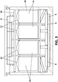
- the integral system comprises a water inlet 1 for the entry of water to be treated into a tank 22, a flotation or aggregation section 15, and a filtration section 16 with membranes 11 seen in this drawing as a pack, although there can be several of them (see Figure 3 ).
- the membranes are preferably submerged ultrafiltration membranes.
- the agitation air collection hood 12 with an air outlet in the upper part 13 can be seen arranged over the membranes. Air is injected through the membranes while cleaning said membranes 11 in the filtration area.
- the sludge collection carriage 8 preferably has a longitudinal translational movement (see arrows) for longitudinal translation to and from the upper sludge collection receptacle 3.
- the surface scraper 10 is responsible for driving the continuous sludge layer that builds up on the surface once the particles have gone through the membranes. Sludge precipitated at the lower part is directed with the lower scraper 9 to purging drains 4 and 5 located in the aggregation area 15 and in the filtration area 16, respectively.
- a system consisting of lamellae 7 which prevent a turbulent flow from occurring can be incorporated so as to increase the working speed in the DAF area, making it the same as the working speed of the UF area, and therefore increasing performance.
- the lamellae usually have an inclination between 45° and 60°.
- the lower scraper is divided into segments to keep clear of posts for holding the UF membrane packs which are placed widthwise inside the tank 22 (the width of the tank is understood as the direction perpendicular to the water inlet, which would be the longitudinal dimension).
- the membrane packs are placed on supports having the same width as said pack, but the supports are anchored either to the bottom of the tank 22 or to its side walls by means of thinner posts, leaving room for the segments of the lower scraper.
- Both the upper scraper and the lower scraper are additionally provided with a lifting system. In the case of the upper scraper, this is necessary so that the surface sludge does not consolidate in areas other than the collection areas. In the case of the lower scraper, it allows being used at the same time as the upper scraper or preventing the use thereof when it is not necessary.
- the water is subjected to a coagulation process in tank 20 and a flocculation process in tank 21.
- the raw water thus treated passes through the inlet 1 through a valve 31 into tank 22 to be treated in the first DAF section which can optionally include the lamellae 7 as explained above. Part of the contaminants will move upwards to the surface of the tank entrained by air bubbles and another part will remain in the water until the second DAF section where the method is repeated.
- the water then passes into the filtration area 16.
- the clarified water leaves the tank 22 through valve 6 and is partly recirculated through conduit 25 as a result of pressurization pump 30.
- the clarified water is saturated by means of air inlet 26 and once it is depressurized in valve 29, it is recirculated to tank 22, which favors flotation and concentration by particle flotation.
Landscapes
- Life Sciences & Earth Sciences (AREA)
- Hydrology & Water Resources (AREA)
- Engineering & Computer Science (AREA)
- Environmental & Geological Engineering (AREA)
- Water Supply & Treatment (AREA)
- Chemical & Material Sciences (AREA)
- Organic Chemistry (AREA)
- Separation Using Semi-Permeable Membranes (AREA)
Priority Applications (1)
| Application Number | Priority Date | Filing Date | Title |
|---|---|---|---|
| EP18382464.8A EP3587357A1 (de) | 2018-06-22 | 2018-06-22 | System zur behandlung von wasser mittels druckentspannungsflotation und filtrationsmembranen |
Applications Claiming Priority (1)
| Application Number | Priority Date | Filing Date | Title |
|---|---|---|---|
| EP18382464.8A EP3587357A1 (de) | 2018-06-22 | 2018-06-22 | System zur behandlung von wasser mittels druckentspannungsflotation und filtrationsmembranen |
Publications (1)
| Publication Number | Publication Date |
|---|---|
| EP3587357A1 true EP3587357A1 (de) | 2020-01-01 |
Family
ID=63449412
Family Applications (1)
| Application Number | Title | Priority Date | Filing Date |
|---|---|---|---|
| EP18382464.8A Withdrawn EP3587357A1 (de) | 2018-06-22 | 2018-06-22 | System zur behandlung von wasser mittels druckentspannungsflotation und filtrationsmembranen |
Country Status (1)
| Country | Link |
|---|---|
| EP (1) | EP3587357A1 (de) |
Cited By (2)
| Publication number | Priority date | Publication date | Assignee | Title |
|---|---|---|---|---|
| CN117185524A (zh) * | 2023-08-29 | 2023-12-08 | 浙江坚膜科技有限公司 | 一种二次气浮水处理系统及方法 |
| CN121135059A (zh) * | 2025-11-04 | 2025-12-16 | 北京市自来水集团有限责任公司第九水厂 | 气浮外压式膜一体化水处理系统 |
Citations (2)
| Publication number | Priority date | Publication date | Assignee | Title |
|---|---|---|---|---|
| US20040217058A1 (en) | 2002-12-19 | 2004-11-04 | Jason Cadera | Integrated dissolved air flotation and immersed membrane filtration apparatus and method for using same |
| US20150136697A1 (en) * | 2013-11-18 | 2015-05-21 | Toyo Engineering Corporation | Oily water separator, oil-water separating method and filtration membrane unit |
-
2018
- 2018-06-22 EP EP18382464.8A patent/EP3587357A1/de not_active Withdrawn
Patent Citations (2)
| Publication number | Priority date | Publication date | Assignee | Title |
|---|---|---|---|---|
| US20040217058A1 (en) | 2002-12-19 | 2004-11-04 | Jason Cadera | Integrated dissolved air flotation and immersed membrane filtration apparatus and method for using same |
| US20150136697A1 (en) * | 2013-11-18 | 2015-05-21 | Toyo Engineering Corporation | Oily water separator, oil-water separating method and filtration membrane unit |
Cited By (2)
| Publication number | Priority date | Publication date | Assignee | Title |
|---|---|---|---|---|
| CN117185524A (zh) * | 2023-08-29 | 2023-12-08 | 浙江坚膜科技有限公司 | 一种二次气浮水处理系统及方法 |
| CN121135059A (zh) * | 2025-11-04 | 2025-12-16 | 北京市自来水集团有限责任公司第九水厂 | 气浮外压式膜一体化水处理系统 |
Similar Documents
| Publication | Publication Date | Title |
|---|---|---|
| JP5033130B2 (ja) | 浄水装置および実施方法 | |
| KR100919367B1 (ko) | 고효율 기체용해탱크를 이용한 부상분리장치 | |
| KR101281514B1 (ko) | 마이크로버블 유닛과 경사판 구조를 갖는 가압 부상식 오염수 처리방법 | |
| KR101820864B1 (ko) | 섬유볼을 내장한 용존 공기 부상형 전처리 장치 및 이를 이용한 용존 공기 부상형 수처리 방법 | |
| RU2630541C2 (ru) | Устройство и способ для очистки соленой воды | |
| KR101278958B1 (ko) | 폐수처리시스템 | |
| US20170297924A1 (en) | Water treatment process employing dissolved air flotation to remove suspended solids | |
| KR20160029272A (ko) | 다단 기포주입 부상분리조를 이용한 간이 하 폐수 처리 시스템 및 이를 이용한 간이 하 폐수 처리 방법 | |
| UA80273C2 (en) | Method and device for an enlightenment of fluids, in particular the water, saturated with material in the form of suspension | |
| KR100898080B1 (ko) | 가압 부상식 여과지 | |
| KR20160032067A (ko) | 다단 기포주입 부상분리조를 이용한 간이 하 폐수 처리 시스템 및 이를 이용한 간이 하 폐수 처리 방법 | |
| WO2013040002A1 (en) | Enhanced separation of nuisance materials from wastewater | |
| CN204281479U (zh) | 一种涂装废水的处理系统 | |
| JP4246087B2 (ja) | 含油廃水処理装置 | |
| KR101773379B1 (ko) | 사이클론을 포함하는 수평형 유도가스 부상분리를 이용한 유수처리 장치 및 그 방법 | |
| KR101539727B1 (ko) | 전기응집과 전자석을 이용한 총인 제거방법 및 장치 | |
| EP3613487A1 (de) | System zur entfernung von dekantierten produkten in einem flotationswasserbehandlungssystem mit gelöster luft und hoher hydraulischer last | |
| EP1197474A1 (de) | Wasserbehandlung durch verjüngende Ausflockung | |
| JP7327972B2 (ja) | 凝集沈殿処理装置及び凝集沈殿処理装置の運転方法 | |
| CN105174558A (zh) | 一种造气废水除油的预处理方法 | |
| KR100869312B1 (ko) | 오수 부상분리처리조 | |
| KR200330431Y1 (ko) | 유수 분리기 | |
| KR101773378B1 (ko) | 미스트제거기를 포함하는 수평형유도가스 부상분리 유수처리 장치 및 그 방법 | |
| CN105347563B (zh) | 一种气浮和过滤一体化装置 | |
| JP4129479B1 (ja) | 汚泥の処理方法及びその処理システム |
Legal Events
| Date | Code | Title | Description |
|---|---|---|---|
| PUAI | Public reference made under article 153(3) epc to a published international application that has entered the european phase |
Free format text: ORIGINAL CODE: 0009012 |
|
| STAA | Information on the status of an ep patent application or granted ep patent |
Free format text: STATUS: THE APPLICATION HAS BEEN PUBLISHED |
|
| AK | Designated contracting states |
Kind code of ref document: A1 Designated state(s): AL AT BE BG CH CY CZ DE DK EE ES FI FR GB GR HR HU IE IS IT LI LT LU LV MC MK MT NL NO PL PT RO RS SE SI SK SM TR |
|
| AX | Request for extension of the european patent |
Extension state: BA ME |
|
| RAP1 | Party data changed (applicant data changed or rights of an application transferred) |
Owner name: TECNOQUIMICA EXTERIOR, S.A.U. (TECEXSA) |
|
| STAA | Information on the status of an ep patent application or granted ep patent |
Free format text: STATUS: REQUEST FOR EXAMINATION WAS MADE |
|
| 17P | Request for examination filed |
Effective date: 20200630 |
|
| RBV | Designated contracting states (corrected) |
Designated state(s): AL AT BE BG CH CY CZ DE DK EE ES FI FR GB GR HR HU IE IS IT LI LT LU LV MC MK MT NL NO PL PT RO RS SE SI SK SM TR |
|
| GRAP | Despatch of communication of intention to grant a patent |
Free format text: ORIGINAL CODE: EPIDOSNIGR1 |
|
| STAA | Information on the status of an ep patent application or granted ep patent |
Free format text: STATUS: GRANT OF PATENT IS INTENDED |
|
| RIC1 | Information provided on ipc code assigned before grant |
Ipc: C02F 1/24 20060101AFI20201106BHEP Ipc: C02F 1/44 20060101ALI20201106BHEP |
|
| INTG | Intention to grant announced |
Effective date: 20201208 |
|
| RIN1 | Information on inventor provided before grant (corrected) |
Inventor name: SALUTREGUI ARMAS, JOSE, MANUEL |
|
| STAA | Information on the status of an ep patent application or granted ep patent |
Free format text: STATUS: THE APPLICATION IS DEEMED TO BE WITHDRAWN |
|
| 18D | Application deemed to be withdrawn |
Effective date: 20210420 |