EP3587423A1 - Organische verbindungen und diese enthaltende organische elektrolumineszenzvorrichtung - Google Patents
Organische verbindungen und diese enthaltende organische elektrolumineszenzvorrichtung Download PDFInfo
- Publication number
- EP3587423A1 EP3587423A1 EP18180155.6A EP18180155A EP3587423A1 EP 3587423 A1 EP3587423 A1 EP 3587423A1 EP 18180155 A EP18180155 A EP 18180155A EP 3587423 A1 EP3587423 A1 EP 3587423A1
- Authority
- EP
- European Patent Office
- Prior art keywords
- group
- unsubstituted
- substituted
- formula
- alkyl group
- Prior art date
- Legal status (The legal status is an assumption and is not a legal conclusion. Google has not performed a legal analysis and makes no representation as to the accuracy of the status listed.)
- Withdrawn
Links
- 0 C*c1nc2c(*)c(*)c(*)c(C)c2[n]1C Chemical compound C*c1nc2c(*)c(*)c(*)c(C)c2[n]1C 0.000 description 11
- ZHVMXLXJYCIWLK-UHFFFAOYSA-N C[n](c(cccc1)c1c1ccc2[n]3c4c5cccc4)c1c2nc3[n]5-c1ccccc1 Chemical compound C[n](c(cccc1)c1c1ccc2[n]3c4c5cccc4)c1c2nc3[n]5-c1ccccc1 ZHVMXLXJYCIWLK-UHFFFAOYSA-N 0.000 description 3
- DADCOSPMNXLIQW-UHFFFAOYSA-N C[n]1c2ccc3[n](c(ccc(-c(cc4)cc([n](C)c5c6)c4c5cc([n]4c5c7cccc5)c6nc4[n]7-c4ccccc4)c4)c4[n]4-c5ccccc5)c4nc3c2c2c1cccc2 Chemical compound C[n]1c2ccc3[n](c(ccc(-c(cc4)cc([n](C)c5c6)c4c5cc([n]4c5c7cccc5)c6nc4[n]7-c4ccccc4)c4)c4[n]4-c5ccccc5)c4nc3c2c2c1cccc2 DADCOSPMNXLIQW-UHFFFAOYSA-N 0.000 description 2
- QOKOVGLUKMQQFN-UHFFFAOYSA-N Oc1cccc([Zn])c1O Chemical compound Oc1cccc([Zn])c1O QOKOVGLUKMQQFN-UHFFFAOYSA-N 0.000 description 2
- MGNZXYYWBUKAII-UHFFFAOYSA-N C1C=CC=CC1 Chemical compound C1C=CC=CC1 MGNZXYYWBUKAII-UHFFFAOYSA-N 0.000 description 1
- WNHPSFKWJNJJSI-UHFFFAOYSA-N C=[Br]c(cccc1[n]2-c3ccccc3)c1[n]1c2nc2c1cccc2 Chemical compound C=[Br]c(cccc1[n]2-c3ccccc3)c1[n]1c2nc2c1cccc2 WNHPSFKWJNJJSI-UHFFFAOYSA-N 0.000 description 1
- TWTXGXQPPMUKGR-UHFFFAOYSA-N CC(N(c1cccc(Nc(cccc2)c2Cl)c11)C2=CCCC=C2)N1c(cccc1)c1N Chemical compound CC(N(c1cccc(Nc(cccc2)c2Cl)c11)C2=CCCC=C2)N1c(cccc1)c1N TWTXGXQPPMUKGR-UHFFFAOYSA-N 0.000 description 1
- XMWINMVFKPHMJB-UHFFFAOYSA-N CC1=CCCC=C1 Chemical compound CC1=CCCC=C1 XMWINMVFKPHMJB-UHFFFAOYSA-N 0.000 description 1
- UZPWKTCMUADILM-SSDOTTSWSA-N C[C@@H]1C=CCCC1 Chemical compound C[C@@H]1C=CCCC1 UZPWKTCMUADILM-SSDOTTSWSA-N 0.000 description 1
- MAJZKJGBJFLBHN-UHFFFAOYSA-N C[n](c1ccccc1c1c2)c1cc1c2[n](c(cccc2)c2[n]2-c3cc(-c4cccc(-[n]5c6nc(cccc7)c7[n]6c6c5cc(c5ccccc5[n]5I)c5c6)c4)ccc3)c2n1 Chemical compound C[n](c1ccccc1c1c2)c1cc1c2[n](c(cccc2)c2[n]2-c3cc(-c4cccc(-[n]5c6nc(cccc7)c7[n]6c6c5cc(c5ccccc5[n]5I)c5c6)c4)ccc3)c2n1 MAJZKJGBJFLBHN-UHFFFAOYSA-N 0.000 description 1
- LRYSWKNTGBMEDL-UHFFFAOYSA-N C[n]1c(cc(c([n]2c3nc4c2cccc4)c2)[n]3-c3ccccc3)c2c2ccccc12 Chemical compound C[n]1c(cc(c([n]2c3nc4c2cccc4)c2)[n]3-c3ccccc3)c2c2ccccc12 LRYSWKNTGBMEDL-UHFFFAOYSA-N 0.000 description 1
- LRZCCXVFBKNBQP-LICLKQGHSA-N C[n]1c2c3[n](c(cccc4)c4[n]4/C(/C=C)=C/C=C)c4nc3ccc2c2c1cccc2 Chemical compound C[n]1c2c3[n](c(cccc4)c4[n]4/C(/C=C)=C/C=C)c4nc3ccc2c2c1cccc2 LRZCCXVFBKNBQP-LICLKQGHSA-N 0.000 description 1
- SISBZXQUWWUQDG-UHFFFAOYSA-N I[n](c1ccccc1c1c2)c1cc([n]1c3nc4c1cccc4)c2[n]3C1=CCCC=C1 Chemical compound I[n](c1ccccc1c1c2)c1cc([n]1c3nc4c1cccc4)c2[n]3C1=CCCC=C1 SISBZXQUWWUQDG-UHFFFAOYSA-N 0.000 description 1
- BIGCFZQUHHSLPR-UHFFFAOYSA-N I[n]1c(c([n]2-c3ccccc3)c(cc3)[n]4c2nc2c4cccc2)c3c2c1cccc2 Chemical compound I[n]1c(c([n]2-c3ccccc3)c(cc3)[n]4c2nc2c4cccc2)c3c2c1cccc2 BIGCFZQUHHSLPR-UHFFFAOYSA-N 0.000 description 1
- NMYNUWMGLKRSNT-UHFFFAOYSA-N N#Cc(c(-[n](c1ccccc1c1ccc2[n]3c4c5cccc4)c1c2nc3[n]5-c1ccccc1)ccc1)c1F Chemical compound N#Cc(c(-[n](c1ccccc1c1ccc2[n]3c4c5cccc4)c1c2nc3[n]5-c1ccccc1)ccc1)c1F NMYNUWMGLKRSNT-UHFFFAOYSA-N 0.000 description 1
- BNBRIFIJRKJGEI-UHFFFAOYSA-N N#Cc(c(F)ccc1)c1F Chemical compound N#Cc(c(F)ccc1)c1F BNBRIFIJRKJGEI-UHFFFAOYSA-N 0.000 description 1
- SFTUVBGUNGIOCU-UHFFFAOYSA-N Oc(cc1[Zn])ccc1O Chemical compound Oc(cc1[Zn])ccc1O SFTUVBGUNGIOCU-UHFFFAOYSA-N 0.000 description 1
- QUGMSFVGVWDVQN-UHFFFAOYSA-N Oc(cccc1O)c1[Zn] Chemical compound Oc(cccc1O)c1[Zn] QUGMSFVGVWDVQN-UHFFFAOYSA-N 0.000 description 1
- DSDFNVGVKDKAQY-UHFFFAOYSA-N Oc1c(-c(cccc2[Zn])c2O)c([Zn])ccc1 Chemical compound Oc1c(-c(cccc2[Zn])c2O)c([Zn])ccc1 DSDFNVGVKDKAQY-UHFFFAOYSA-N 0.000 description 1
- DOVCNHQPJVQIKK-UHFFFAOYSA-N c(cc1)ccc1-[n]1c2nc3c4[nH]c5ccccc5c4ccc3[n]2c2c1cccc2 Chemical compound c(cc1)ccc1-[n]1c2nc3c4[nH]c5ccccc5c4ccc3[n]2c2c1cccc2 DOVCNHQPJVQIKK-UHFFFAOYSA-N 0.000 description 1
- YGQBSFDXUBZWSA-UHFFFAOYSA-N c(cc1)ccc1[Si](c1ccccc1)(c1ccccc1)c(cc1c2c3)ccc1[o]c2ccc3-[n]1c2ccccc2c2c1cccc2 Chemical compound c(cc1)ccc1[Si](c1ccccc1)(c1ccccc1)c(cc1c2c3)ccc1[o]c2ccc3-[n]1c2ccccc2c2c1cccc2 YGQBSFDXUBZWSA-UHFFFAOYSA-N 0.000 description 1
Images


Classifications
-
- C—CHEMISTRY; METALLURGY
- C07—ORGANIC CHEMISTRY
- C07D—HETEROCYCLIC COMPOUNDS
- C07D487/00—Heterocyclic compounds containing nitrogen atoms as the only ring hetero atoms in the condensed system, not provided for by groups C07D451/00 - C07D477/00
- C07D487/12—Heterocyclic compounds containing nitrogen atoms as the only ring hetero atoms in the condensed system, not provided for by groups C07D451/00 - C07D477/00 in which the condensed system contains three hetero rings
- C07D487/14—Ortho-condensed systems
Definitions
- the present invention relates to a condensed benzimidazolo[1,2-a]benzimidazole carrying aryl- or heteroarylnitril, a process for preparing said condensed benzimidazolo[1,2-a]benzimidazole carrying aryl- or heteroarylnitril, an organic electroluminescence device comprising said condensed benzimidazolo[1,2-a]benzimidazole carrying aryl- or heteroarylnitril, an electronic device comprising said organic electroluminescence device, an emitting layer comprising at least one inventive condensed benzimidazolo[1,2-a]benzimidazole carrying aryl- or heteroarylnitril and the use of said inventive condensed benzimidazolo[1,2-a]benzimidazole carrying aryl- or heteroarylnitril in an electronic device as a delayed-fluorescent emitter and/or as a host material.
- organic electroluminescence device When a voltage is applied to an organic electroluminescence device (hereinafter, occasionally referred to as "organic EL device"), holes and electrons are injected into an emitting layer respectively from an anode and a cathode. The injected holes and electrons are recombined to generate excitons in the emitting layer. According to the electron spin statistics theory, singlet excitons are generated at a ratio of 25% and triplet excitons are generated at a ratio of 75%.
- a fluorescent organic EL device which uses emission caused by singlet excitons, is applied to a full color display of a mobile phone, a TV set and the like. It has been studied to further improve a performance of the fluorescent organic EL device. For instance, in order to further improve a luminous efficiency, an organic EL device with use of singlet excitons and triplet excitons has been studied.
- thermally activated delayed fluorescence refers to, for instance, " ADACHI, Chihaya, ed. (March 22, 2012), "Yuki Hando-tai no Debaisu Bussei (Device Physics of Organic Semiconductors)", Kodansha, pp. 261-262 ".
- Dongdong Zhang et al., 26, 29, 2014, 5050-5055 concerns materials with small singlet-triplet splits ( ⁇ E ST s) as sensitizing hosts to excite fluorescent dopants, breaking the trade-off between small ⁇ E ST and high radiative decay rates.
- ⁇ E ST s small singlet-triplet splits
- a highly efficient orange-fluorescent organic light-emitting diode (OLED) is prepared, showing a maximum external quantum efficiency of 12.2%.
- the following material is mentioned as sensitizing host:
- WO2016/157113 A1 concerns benzimidazolo[1,2-a]benzimidazole carrying aryl- or heteroarylnitril groups for organic light emitting diodes. Said compounds of formula show low singlet triplet splitting, which makes them useful as TADF ( Thermally Activated Delayed Fluorescence, Adv. Mater. 2014, 26, 7931-7958 ) emitter or TADF host materials in combination with fluorescent emitters.
- TADF Thermally Activated Delayed Fluorescence, Adv. Mater. 2014, 26, 7931-7958
- WO 2017/115596 A1 concerns a heat-activated delayed-fluorescence organic electroluminescence element that includes a luminescent layer between a positive electrode and a negative electrode that face.
- the organic electroluminescence element contains, in at least one luminescent layer, a heat-activated delayed-fluorescence material or a heat-activated delayed-fluorescence material and a host material.
- the heat-activated delayed-fluorescence material is represented by general formula (1), wherein A is an electron-withdrawing group such as a CN group and D 1 and D 2 are electron-donating groups that have an indole-ring structure:
- KR2017/0081438 discloses compounds of the following formula and organic optoelectronic devices comprising said compounds as hosts for green phosphorescent emitters.
- An object of the invention is to provide a compound useful in an organic electroluminescence device capable of prolonging the lifetime, improving the luminous efficiency, and inhibiting the roll-off when driven at a high current density, and an electronic device including the organic electroluminescence device.
- a compound should be provided useful in an organic electroluminescence device capable of improving luminous efficiency, especially at high current.
- compounds suitable for use in an organic electroluminescence device capable of prolonging a lifetime, improving a luminous efficiency, and inhibiting a roll-off when driven at a high current density, an organic electroluminescence device, and an electronic device including the organic electroluminescence device can be provided.
- the compounds are useful in an organic electroluminescence device capable of improving luminous efficiency, especially at high current.
- the compounds of the present invention are characterized by a good suitability as TADF hosts or emitters in a TADF emitter system.
- the compounds of the present invention may be used for electrophotographic photoreceptors, photoelectric converters, organic solar cells (organic photovoltaics), switching elements, such as organic transistors, for example, organic FETs and organic TFTs, organic light emitting field effect transistors (OLEFETs), image sensors, dye lasers and electroluminescence devices, such as, for example, organic light-emitting diodes (OLEDs).
- organic photoreceptors organic solar cells
- organic solar cells organic photovoltaics
- switching elements such as organic transistors, for example, organic FETs and organic TFTs, organic light emitting field effect transistors (OLEFETs), image sensors, dye lasers and electroluminescence devices, such as, for example, organic light-emitting diodes (OLEDs).
- a further subject of the present invention is directed to an electronic device, comprising a compound according to the present invention.
- the electronic device is preferably an electroluminescence device, such as an organic light-emitting diode (OLED).
- OLED organic light-emitting diode
- the compounds of formula (I) are preferably used as TADF emitter materials, or TADF host materials in combination with at least one fluorescent emitter.
- a further subject of the present invention is directed to an emitting layer, comprising a compound of formula (I) according to the present invention.
- a compound of formula (I) is preferably used as TADF emitter material, or TADF host material in combination with at least one fluorescent emitter.
- XX to YY carbon atoms referred to by "a substituted or unsubstituted group ZZ having XX to YY carbon atoms” used herein is the number of carbon atoms of the unsubstituted group ZZ and does not include any carbon atom in the substituent of the substituted group ZZ.
- YY is larger than “XX” and each of "XX” and “YY” represents an integer of 1 or more.
- XX to YY atoms referred to by "a substituted or unsubstituted group ZZ having XX to YY atoms” used herein is the number of atoms of the unsubstituted group ZZ and does not include any atom in the substituent of the substituted group ZZ.
- YY is larger than “XX” and each of "XX” and “YY” represents an integer of 1 or more.
- C ZZ -C YY - referred to by "C ZZ -C YY -ZZ group which is unsubstituted or substituted” used herein is the number of carbon atoms of the unsubstituted group ZZ and does not include any heteroatom or any atom in the substituent of the substituted group ZZ.
- YY is larger than “XX” and each of "XX” and “YY” represents an integer of 1 or more.
- unsubstituted group ZZ referred to by "a substituted or unsubstituted group ZZ" used herein means the group ZZ wherein no hydrogen atom is substituted by a substituent.
- the number of "ring carbon atoms" ("a ring formed of carbon atoms") referred to herein means the number of the carbon atoms included in the atoms which are members forming the ring itself of a compound in which a series of atoms is bonded to form the ring (for example, a monocyclic compound, a fused ring compound, a cross-linked compound, a carbocyclic compound, and a heterocyclic compound). If the ring has a substituent, the carbon atom in the substituent is not included in the ring carbon atom. The same applies to the number of "ring carbon atom” described below, unless otherwise noted.
- a benzene ring has 6 ring carbon atoms
- a naphthalene ring has 10 ring carbon atoms
- a pyridinyl group has 5 ring carbon atoms
- a furanyl group has 4 ring carbon atoms. If a benzene ring or a naphthalene ring has, for example, an alkyl substituent, the carbon atom in the alkyl substituent is not counted as the ring carbon atom of the benzene or naphthalene ring.
- the number of "ring atom" ("a ring formed of atoms") referred to herein means the number of the atoms which are members forming the ring itself (for example, a monocyclic ring, a fused ring, and a ring assembly) of a compound in which a series of atoms is bonded to form the ring (for example, a monocyclic compound, a fused ring compound, a cross-linked compound, a carbocyclic compound, and a heterocyclic compound).
- the atom not forming the ring for example, hydrogen atom(s) for saturating the valence of the atom which forms the ring
- the atom in a substituent if the ring is substituted, are not counted as the ring atom.
- a pyridine ring has 6 ring atoms
- a quinazoline ring has 10 ring atoms
- a furan ring has 5 ring atoms.
- the hydrogen atom on the ring carbon atom of a pyridine ring or a quinazoline ring and the atom in a substituent are not counted as the ring atom.
- hydroxide atom used herein includes isotopes different in the neutron numbers, i.e., light hydrogen (protium), heavy hydrogen (deuterium), and tritium.
- Halogen is fluorine, chlorine, bromine and iodine.
- C 1 -C 25 alkyl (C 1 -C 18 alkyl) is typically linear or branched, where possible. Examples are methyl, ethyl, n-propyl, isopropyl, n-butyl, sec.-butyl, isobutyl, tert.-butyl, n-pentyl, 2-pentyl, 3-pentyl, 2,2-dimethylpropyl, 1,1,3,3-tetramethylpentyl, n-hexyl, 1-methylhexyl, 1,1,3,3,5,5-hexamethylhexyl, n-heptyl, isoheptyl, 1,1,3,3-tetramethylbutyl, 1-methylheptyl, 3-methylheptyl, n-octyl, 1,1,3,3-tetramethylbutyl and 2-ethylhexyl, n-nonyl, decyl, undecyl, dodecy
- C 1 -C 8 alkyl is typically methyl, ethyl, n-propyl, isopropyl, n-butyl, sec.-butyl, isobutyl, tert.-butyl, n-pentyl, 2-pentyl, 3-pentyl, 2,2-dimethyl-propyl, n-hexyl, n-heptyl, n-octyl, 1,1,3,3-tetramethylbutyl and 2-ethylhexyl.
- Preferred alkyl groups are C 1 -C 4 alkyl groups.
- C 1 -C 4 alkyl is typically methyl, ethyl, n-propyl, isopropyl, n-butyl, sec.-butyl, isobutyl, tert.-butyl. More preferred alkyl groups are methyl, isopropyl and tert.-butyl.
- the alkyl groups may be substituted by one or more halogens and form halogenated alkyl groups (haloalkyl groups).
- halogenated alkyl groups are a fluoromethyl group, difluoromethyl group, trifluoromethyl group, fluoroethyl group, trifluoromethylmethyl group, trifluoroethyl group and pentafluoroethyl group.
- C 1 -C 25 alkoxy groups are straight-chain or branched alkoxy groups, e.g. methoxy, ethoxy, n-propoxy, isopropoxy, n-butoxy, sec-butoxy, tert-butoxy, amyloxy, isoamyloxy or tert-amyloxy, heptyloxy, octyloxy, isooctyloxy, nonyloxy, decyloxy, undecyloxy, dodecyloxy, tetradecyloxy, pentadecyloxy, hexadecyloxy, heptadecyloxy and octadecyloxy.
- C 1 -C 8 alkoxy examples are methoxy, ethoxy, n-propoxy, isopropoxy, n-butoxy, sec.-butoxy, isobutoxy, tert.-butoxy, n-pentyloxy, 2-pentyloxy, 3-pentyloxy, 2,2-dimethylpropoxy, n-hexyloxy, n-heptyloxy, n-octyloxy, 1,1,3,3-tetramethylbutoxy and 2-ethylhexyloxy, preferably C 1 -C 4 alkoxy such as typically methoxy, ethoxy, n-propoxy, isopropoxy, n-butoxy, sec.-butoxy, isobutoxy, tert.-butoxy.
- cycloalkyl group is typically C 5 -C 12 cycloalkyl, such as cyclopentyl, cyclohexyl, cycloheptyl, cyclooctyl, cyclononyl, cyclodecyl, cycloundecyl, cyclododecyl, preferably cyclopentyl, cyclohexyl, cycloheptyl, or cyclooctyl, which may be unsubstituted or substituted. More preferred cycloalkyl groups are cyclopentyl and cyclohexyl, which may be unsubstituted or substituted.
- C 6 -C 24 aryl (preferably C 6 -C 18 aryl), which optionally can be substituted, is typically phenyl, 4-methylphenyl, 4-methoxyphenyl, naphthyl, especially 1-naphthyl, or 2-naphthyl, biphenylyl, ter-phenylyl, pyrenyl, 2- or 9-fluorenyl, phenanthryl, or anthryl, which may be unsubstituted or substituted. More preferred aryl groups are C 6 -C 10 aryl groups which are unsubstituted or substituted.
- Phenyl, 1-naphthyl and 2-naphthyl are examples of a C 6 -C 10 aryl group. Most preferred is a phenyl group which is unsubstituted or substituted. Further most preferred is an unsubstituted phenyl group.
- C 6 -C 24 aryloxy which optionally can be substituted, is typically C 6 -C 10 aryloxy, which optionally can be substituted by one, or more C 1 -C 8 alkyl and/or C 1 -C 8 alkoxy groups, such as, for example, phenoxy, 1-naphthoxy, or 2-naphthoxy.
- C 7 -C 25 aralkyl is typically benzyl, 2-benzyl-2-propyl, ⁇ -phenyl-ethyl, ⁇ , ⁇ -dimethylbenzyl, ⁇ -phenyl-butyl, ⁇ , ⁇ -dimethyl- ⁇ -phenyl-butyl, ⁇ -phenyl-dodecyl, ⁇ -phenyl-octadecyl, ⁇ -phenyleicosyl or ⁇ -phenyl-docosyl, preferably C 7 -C 18 aralkyl such as benzyl, 2-benzyl-2-propyl, ⁇ -phenyl-ethyl, ⁇ , ⁇ -dimethylbenzyl, ⁇ -phenyl-butyl, ⁇ , ⁇ -dimethyl- ⁇ -phenyl-butyl, ⁇ -phenyl-dodecyl or ⁇ -phenyl-octadecyl, and particularly preferred C 7 -
- C 2 -C 30 heteroaryl (preferably C 2 -C 13 heteroarylaryl) represents a ring with five to seven ring atoms or a condensed ring system, wherein nitrogen, oxygen or sulfur are the possible hetero atoms, and is typically a heterocyclic group with five to 30 atoms having at least six conjugated ⁇ -electrons such as thienyl, benzothiophenyl, dibenzothiophenyl, thianthrenyl, furyl, furfuryl, 2H-pyranyl, benzofuranyl, isobenzofuranyl, dibenzofuranyl, phenoxythienyl, pyrrolyl, imidazolyl, pyrazolyl, pyridyl, bipyridyl, triazinyl, pyrimidinyl, pyrazinyl, pyridazinyl, indolizinyl, isoindolyl, indolyl, indazolyl, pur
- Benzimidazo[1,2-a]benzimidazo-5-yl, benzimidazo[1,2-a]benzimidazo-2-yl, carbazolyl and dibenzofuranyl are examples of a C 2 -C 14 heteroaryl group.
- a C 2 -C 13 heteroaryl group is for example, benzimidazo[1,2-a]benzimidazo-5-yl ( benzimidazo[1,2-a]benzimidazo-2-yl ( benzimidazolo[2,1-b][1,3]benzothiazolyl, benzimidazolo[2,1-b][1,3]benzoxazole, carbazolyl, dibenzofuranyl, or dibenzotihophenyl, which can be unsubstituted or substituted, especially by C 6 -C 10 aryl, or C 6 -C 10 aryl, which is substituted by C 1 -C 4 alkyl; or C 2 -C 13 heteroaryl.
- C 2 -C 30 heteroaryl (preferably C 2 -C 13 heteroarylaryl) means that the heteroaryl residue comprises at least 2 carbon atoms and at most 30 carbon atoms in the base skeleton (without substituents).
- the further atoms in the heteroaryl base skeleton are heteroatoms (N, O and/or S).
- R 24' is in each case independently C 1 -C 18 alkyl, such as methyl, ethyl, n-propyl, iso-propyl, n-butyl, isobutyl, sec-butyl, hexyl, octyl, or 2-ethyl-hexyl, or C 6 -C 14 aryl, such as phenyl, tolyl, naphthyl, phenanthronyl, triphenylenyl, fluoranthenyl or biphenylyl
- C 6 -C 24 arylene groups are typically phenylene, 4-methylphenylene, 4-methoxyphenylene, naphthylene, especially 1-naphthylene, or 2-naphthylene, biphenylylene, terphenylylene, pyrenylene, 2- or 9-fluorenylene, phenanthrylene, or anthrylene, which may be unsubstituted or substituted.
- Preferred C 6 -C 24 arylene groups are 1,4-phenylene, 1,3-phenylene, 1,2-phenylene, 3,3'-biphenylylene, 3,3'-m-terphenylene, 2- or 9-fluorenylene, phenanthrylene, or 4-t-butyl-phenylene, which may be unsubstituted or substituted. More preferred arylene groups are 1,4-phenylene, 1,3-phenylene, 1,2-phenylene groups and 4-t-butyl-phenylene.
- C 2 -C 30 heteroarylene groups which optionally can be substituted, represent a ring with five to seven ring atoms or a condensed ring system comprising at least one heteroatom. Nitrogen, oxygen or sulfur are the possible hetero atoms.
- Typical heteroarylene groups are heterocyclic groups with five to 30 atoms having at least six conjugated -electrons such as thienylene, benzothiophenylene, dibenzothiophenylene, thianthrenylene, furylene, furfurylene, 2H-pyranylene, benzofuranylene, isobenzofuranylene, dibenzofuranylene, phenoxythienylene, pyrrolylene, imidazolylene, pyrazolylene, pyridylene, bipyridylene, triazinylene, pyrimidinylene, pyrazinylene, pyridazinylene, indolizinylene, isoindolylene, indolylene, indazolylene, purinylene, quinolizinylene, chinolylene, isochinolylene, phthalazinylene, naphthyridinylene, chinoxalinylene, chinazolinylene, cinnolin
- Preferred C 2 -C 30 heteroarylen groups are pyridylene, triazinylene, pyrimidinylene, carbazolylene, dibenzofuranylene and benzimidazo[1,2-a]benzimidazo-2,5-ylene (which can be unsubstituted or substituted, especially by C 6 -C 10 aryl, C 6 -C 10 aryl which is substituted by C 1 -C 4 alkyl; or C 2 -C 14 heteroaryl.
- Suitable substituents of the abovementioned groups are the groups E mentioned above and below.
- a substituent occurs more than one time in a group, it can be different in each occurrence.
- substituted by E means that one or more, especially one, two or three substituents E might be present.
- some of the aforementioned groups may be substituted by E and/or, if desired, interrupted by D. Interruptions are of course possible only in the case of groups containing at least 2 carbon atoms connected to one another by single bonds; C 6 -C 18 aryl is not interrupted; interrupted arylalkyl contains the unit D in the alkyl moiety.
- a C 1 -C 18 alkyl substituted by one or more E and/or interrupted by one or more units D" or "a C 1 -C 18 alkyl group, which is interrupted by at least one O” is for example, (CH 2 CH 2 O) 1-9 -R x , where R x is H or C 1 -C 10 alkyl or C 2 -C 10 alkanoyl (e.g.
- R y is C 1 -C 18 alkyl, C 5 -C 12 Cycloalkyl, phenyl, C 7 -C 15 phenylalkyl, and R y ' embraces the same definitions as R y or is H; C 1 -C 8 alkylene-COO-R z , e.g.
- D is -CO-, -COO-, -S-, -SO-, -SO 2 -, -O-, -NR 17 -, wherein R 17 is C 1 -C 18 alkyl, such as methyl, ethyl, n-propyl, iso-propyl, n-butyl, isobutyl, or sec-butyl, or C 6 -C 14 aryl, such as phenyl, tolyl, naphthyl, or biphenylyl, or C 2 -C 30 heteroaryl, such as, for example, benzimidazo[1,2-a]benzimidazo-2-yl ( carbazolyl, dibenzofuranyl, dibenzothiophenyl, dialkyl fluranthenyl (dimethyl) which can be unsubstituted or substituted by E, especially by C 6 -C 10 aryl, which may in turn be unsubstituted or substituted by C 1
- E is -OR 21 , -SR 21 , -NR 17 R 18 , -COR 20 , -COOR 19 , -CONR 17 R 18 , -CN, -SiR 22 R 23 R 24 , -POR 25 R 27 , halogen, preferably F, a C 6 -C 40 aryl group which is unsubstituted or is substituted by at least one group selected from a C 1 -C 18 alkyl group, a C 1 -C 18 alkoxy group, a C 1 -C 18 alkyl group, which is interrupted by at least one O, a C 6 -C 18 aryl group, which is in turn unsubstituted or substituted by at least one C 1 -C 18 alkyl group or at least one C 1 -C 18 alkoxy group, a C 5 -C 12 cycloalkyl group, which is in turn unsubstituted or substituted by at least one C 1 -C 18 alkyl
- E is CN, F, CF 3 , a C 6 -C 18 aryl group which is unsubstituted or is substituted by at least one group selected from a C 1 -C 18 alkyl group, a C 1 -C 18 alkoxy group, an unsubstituted C 6 -C 18 aryl group, a C 1 -C 18 alkyl group, a C 1 -C 24 heteroaryl group which is unsubstituted or substituted by at least one group selected from a C 1 -C 18 alkyl group, a C 1 -C 18 alkoxy group, an unsubstituted C 6 -C 18 aryl group.
- R 15 and R 16 are independently of each other H, a C 6 -C 18 aryl group which is unsubstituted or substituted by at least one C 1 -C 18 alkyl group or at least one C 1 -C 18 alkoxy group, preferably H, a C 6 -C 10 aryl group which is unsubstituted or substituted by at least one C 1 -C 8 alkyl group or at least one C 1 -C 8 alkoxy group, more preferably H.
- R 17 and R 18 are independently of each other H, a C 6 -C 18 aryl group which is unsubstituted or substituted by at least one C 1 -C 18 alkyl group or at least one C 1 -C 18 alkoxy group, a C 1 -C 18 alkyl group or a C 1 -C 18 alkyl group, which is interrupted by at least one O, or R 17 and R 18 together form a five or six membered aliphatic, aromatic or heteroaromatic ring, which is unsubstituted or substituted by at least one group E,
- R 17 and R 18 are independently of each other a C 6 -C 10 aryl group which is unsubstituted or substituted by at least one C 1 -C 8 alkyl group or at least one C 1 -C 8 alkoxy group, a C 1 -C 8 alkyl group or a C 1 -C 8 alkoxy group, more preferably a C 6 -C 10 aryl group which is unsubstituted.
- R 19 is H, a C 6 -C 18 aryl group which is unsubstituted or substituted by at least one C 1 -C 18 alkyl group or at least one C 1 -C 18 alkoxy group, a C 1 -C 18 alkyl group or a C 1 -C 18 alkyl group, which is interrupted by at least one O, preferably a C 6 -C 10 aryl group which is unsubstituted or substituted by at least one C 1 -C 8 alkyl group or at least one C 1 -C 8 alkoxy group or a C 1 -C 8 alkyl group, more preferably a C 6 -C 10 aryl group which is unsubstituted or a C 1 -C 8 alkyl group.
- R 20 is H or a C 6 -C 18 aryl group which is unsubstituted or substituted by at least one C 1 -C 18 alkyl group or at least one C 1 -C 18 alkoxy group, a C 1 -C 18 alkyl group or a C 1 -C 18 alkyl group, which is interrupted by at least one O, preferably a C 6 -C 10 aryl group which is unsubstituted or substituted by at least one C 1 -C 8 alkyl group or at least one C 1 -C 8 alkoxy group or a C 1 -C 8 alkyl group, more preferably a C 6 -C 10 aryl group which is unsubstituted or a C 1 -C 8 alkyl group.
- R 21 is independently of each other H, a C 6 -C 18 aryl group which is unsubstituted or substituted by at least one C 1 -C 18 alkyl group or at least one C 1 -C 18 alkoxy group, a C 1 -C 18 alkyl group or a C 1 -C 18 alkyl group, which is interrupted by at least one O, preferably a C 6 -C 10 aryl group which is unsubstituted or substituted by at least one C 1 -C 8 alkyl group or at least one C 1 -C 8 alkoxy group or a C 1 -C 8 alkyl group, more preferably a C 6 -C 10 aryl group which is unsubstituted or a C 1 -C 8 alkyl group.
- R 22 , R 23 and R 24 are independently of each other H, a C 1 -C 18 alkyl group, a C 6 -C 18 aryl group which is unsubstituted or substituted by at least one C 1 -C 18 alkyl group, preferably a C 6 -C 10 aryl group which is unsubstituted or substituted by at least one C 1 -C 8 alkyl group or at least one C 1 -C 8 alkoxy group or a C 1 -C 8 alkyl group, more preferably a C 6 -C 10 aryl group which is unsubstituted or a C 1 -C 8 alkyl group.
- R 25 and R 27 are independently of each other H, a C 1 -C 18 alkyl group, a C 6 -C 18 aryl group which is unsubstituted or substituted by at least one C 1 -C 18 alkyl group, a C 7 -C 25 aralkyl which is unsubstituted or substituted by at least one group E, a C 5 -C 12 cycloalkyl group which is unsubstituted or substituted by at least one group E, preferably a C 6 -C 10 aryl group which is unsubstituted or substituted by at least one C 1 -C 8 alkyl group or at least one C 1 -C 8 alkoxy group or a C 1 -C 8 alkyl group, more preferably a C 6 -C 10 aryl group which is unsubstituted or a C 1 -C 8 alkyl group.
- 0, 1 or 2 preferably 0 or 1, more preferably 0 of the groups X 1 , X 2 , X 3 , X 4 , X 5 and X 6 are N, and 0, 1 or 2, preferably 0 or 1, more preferably 0 of the groups X 13 , X 14 , X 15 , X 16 , X 17 and X 18 are N.
- z is 0 or 1.
- R 1a , R 2a , R 3a , R 4a , R 5a and R 6a in formula (I) are each independently CN, R A , D 1 or D 2 ; wherein 1, 2, 3, 4 or 5, preferably 1, 2, 3 or 4, more preferably 1 or 2 of the residues R 1a , R 2a , R 3a , R 4a , R 5a and R 6a are CN; 0, 1 or 2 of the residues R 1a , R 2a , R 3a , R 4a , R 5a and R 6a are R A ; 0 or 1, 2 preferably 0 or 1, more preferably 1 of the residues R 1a , R 2a , R 3a , R 4a , R 5a and R 6a are D 2 ; and 1 of the residues R 1a , R 2a , R 3a , R 4a , R 5a and R 6a is D 1 .
- the residues CN and D 1 are mandatorily present in the compounds of formula (I), preferably, the residues CN and D 1 are mandatorily present in the compounds of formula (I) and at least one additional residue D 2 , CN or R A are mandatorily present in the compounds of formula (I), and more preferably, the residues CN, D 1 and D 2 are mandatorily present in the compounds of formula (I).
- R 13a , R 14a , R 15a , R 16a , R 17a and R 18a in formula (I) are each independently CN, R A , D 1 or D 2 ; wherein 1, 2, 3 or 4, preferably 1 or 2, more preferably 1 of the residues R 13a , R 14a , R 15a , R 16a , R 17a and R 18a are CN; 0, 1 or 2 of the residues R 13a , R 14a , R 15a , R 16a , R 17a and R 18a are R A ; 0 or 1, more preferably 0 of the residues R 13a , R 14a , R 15a , R 16a , R 17a and R 18a are D 1 ; and 1 of the residues R 13a , R 14a , R 15a , R 16a , R 17a and R 18a is D 2 .
- 0, 1 or 2 preferably 0 or 1, more preferably 0 of the groups X 1 , X 2 , X 3 , X 4 , X 5 and X 6 are N, and 0, 1 or 2, preferably 0 or 1, more preferably 0 of the groups X 13 , X 14 , X 15 , X 16 , X 17 and X 18 are N.
- z is 0 or 1.
- R 1a , R 2a , R 3a , R 4a , R 5a and R 6a in formula (I) are each independently CN, R A , D 1 or D 2 ; wherein 1, 2, 3, 4 or 5, preferably 1, 2, 3 or 4, more preferably 1 or 2 of the residues R 1a , R 2a , R 3a , R 4a , R 5a and R 6a are CN; 0, 1 or 2 of the residues R 1a , R 2a , R 3a , R 4a , R 5a and R 6a are R A ; 0 or 1, 2 preferably 0 or 1, more preferably 1 of the residues R 1a , R 2a , R 3a , R 4a , R 5a and R 6a are D 2 ; and 1 of the residues R 1a , R 2a , R 3a , R 4a , R 5a and R 6a is D 1 .
- the residues CN and D 1 are mandatorily, preferably, the residues CN and D 1 are mandatorily present in the compounds of formula (I*) and at least one additional residue D 2 , CN or R A are mandatorily present in the compounds of formula (I*), and more preferably, the residues CN, D 1 and D 2 are mandatorily present in the compounds of formula (I*).
- R A in the compound of formula (I) is H, a C 1 -C 25 alkyl group which is unsubstituted or substituted by at least one group E and/or interrupted by at least one group D, a C 6 -C 40 aryl group which is unsubstituted or substituted by at least one group E, a C 1 -C 24 heteroaryl group which is unsubstituted or substituted by at least one group E, a C 7 -C 25 aralkyl group which is unsubstituted or substituted by at least one group E, a C 5 -C 12 cycloalkyl group which is unsubstituted or substituted by at least one group E, -OR 21 , -SR 21 , -NR 17 R 18 , -COR 20 , -COOR 19 , -CONR 17 R 18 ,-SiR 22 R 23 R 24 , -POR 25 R 27 , or halogen, or at least two of the residues
- R A is H, a C 1 -C 25 alkyl group which is unsubstituted or substituted by at least one group E and/or interrupted by at least one group D, a C 6 -C 40 aryl group which is unsubstituted or substituted by at least one group E or a C 1 -C 24 heteroaryl group which is unsubstituted or substituted by at least one group E, more preferably H, a C 1 -C 8 alkyl group which is unsubstituted, a C 6 -C 10 aryl group which is unsubstituted or a C 1 -C 24 heteroaryl group which is unsubstituted, most preferably phenyl or H, even more most preferably H.
- D 1 in formula (I) is a group of formula (III) wherein
- R 14 and R 15' are each independently a C 6 -C 40 aryl group which is unsubstituted or substituted by at least one group E or a C 1 -C 24 heteroaryl group which is unsubstituted or substituted by at least one group E, preferably a C 6 -C 10 aryl group which is unsubstituted or substituted by at least one group E or a C 2 -C 13 heteroaryl group which is unsubstituted or substituted by at least one group E, more preferably a C 6 -C 10 aryl group which is unsubstituted or a C 2 -C 13 heteroaryl group which is unsubstituted, most preferably phenyl, wherein one of R 14 and R 15' is a group -(M) m ---, wherein the dotted line is a bonding site to formula (I).
- X 19 , X 20 , X 21 , X 22 , X 23 , X 24 , X 25 and X 26 in the group of formula (III) are CR 1 , CR 2 , CR 3 , CR 4 , CR 5 , CR 6 , CR 7 and CR 8 , and at least two adjacent residues R 1 , R 2 , R 3 , R 4 , R 5 , R 6 , R 7 and R 8 of at least two adjacent groups CR 1 , CR 2 , CR 3 , CR 4 , CR 5 , CR 6 , CR 7 and CR 8 together form a ring of formula (IV).
- At least two adjacent residues R 1 and R 2 , R 5 and R 6 and/or R 7 and R 8 of at least two adjacent groups CR 1 and CR 2 , CR 5 and CR 6 and/or CR 7 and CR 8 together form a ring of formula (IV).
- at least two adjacent residues R 1 and R 2 and/or R 5 and R 6 of at least two adjacent groups CR 1 and CR 2 and/or CR 5 and CR 6 together form a ring of formula (IV).
- two adjacent residues R 1 and of two adjacent groups CR 1 and CR 2 together form a ring of formula (IV).
- X 27 , X 28 , X 29 and X 30 in the group of formula (IV) are CR 9 , CR 10 , CR 11 and CR 12 .
- the remaining residues R 1 to R 8 and R 9 to R 12 are independently of each other H, a C 1 -C 25 alkyl group which is unsubstituted or substituted by at least one group E and/or interrupted by at least one group D, a C 6 -C 40 aryl group which is unsubstituted or substituted by at least one group E or a C 1 -C 24 heteroaryl group which is unsubstituted or substituted by at least one group E, more preferably H, a C 1 -C 8 alkyl group which is unsubstituted, a C 6 -C 10 aryl group which is unsubstituted or a C 1 -C 24 heteroaryl group which is unsubstituted, most preferably H.
- D 1 is therefore a group of formula (IIIA) wherein at least two adjacent residues R 1 to R 8 together form a ring of formula (IVA) wherein R 1 to R 12 , R 14 and R 15' are defined above and below. Further most preferably, R 1 to R 8 and R 9 to R 12 are H.
- D 1 is selected from the group consisting of wherein R 1 to R 12 , R 14 and R 15' are defined above and below. Further even more most preferably, R 1 to R 8 and R 9 to R 12 are H.
- R 1 to R 12 , R 14 and R 15' are defined above and below. Further even more most preferably, R 1 to R 8 and R 9 to R 12 are H.
- D 1 is a group of formula (IIIA-2), wherein R 1 to R 12 , R 14 and R 15' are defined above and below. Further even more most preferably, R 1 to R 8 and R 9 to R 12 are H.
- R 14 in the group of formula (III) and R 15' in the group of formula (IV) are each independently a C 6 -C 40 aryl group which is unsubstituted or substituted by at least one group E or a C 1 -C 24 heteroaryl group which is unsubstituted or substituted by at least one group E, preferably a C 6 -C 10 aryl group which is unsubstituted or substituted by at least one group E or a C 1 -C 14 heteroaryl group which is unsubstituted or substituted by at least one group E, more preferably a C 6 -C 10 aryl group which is unsubstituted or a C 1 -C 14 heteroaryl group which is unsubstituted, most preferably phenyl, wherein one of R 14 and R 15' is a group -(M) m ---, preferably R 15' is a group -(M) m ---, wherein the dotted line is a bonding
- R 14 is phenyl and R 15' is a group -(M) m ---.
- M is a C 6 -C 40 arylene group which is unsubstituted or substituted by at least one group E, a C 1 -C 24 heteroarylene group which is unsubstituted or substituted by at least one group E, a C 1 -C 25 alkylene group which is unsubstituted or substituted by at least one group E and/or interrupted by at least one group D, or a C 2 -C 25 alkenylene group which is unsubstituted or substituted by at least one group E and/or interrupted by at least one group D, preferably a C 6 -C 10 arylene group which is unsubstituted or substituted by at least one group E, a C 1 -C 14 heteroarylene group which is unsubstituted or substituted by at least one group E, a C 1 -C 8 alkylene group which is unsubstituted or substituted by at least one group E and/or interrupted by at least one group D, or a C 2 -C
- n 0, 1 or 2, preferably 0 or 1, more preferably 0,
- Preferred compounds of formula (I) are represented by the following formula: preferably formula (I*A), wherein
- x and y' are each independently 1 or 2, preferably 1; u and t' are 0 or 1; preferably 0, v and w' are each independently 0, 1 or 2, preferably 0 or 1, more preferably 0.
- More preferred compounds of formula (I) are represented by formulae (IA), preferably by formula (I*A) as mentioned above, wherein D 1 is a group of formula (IIIA) wherein at least two adjacent residues R 1 to R 8 together form a ring of formula (IVA) wherein the dotted lines are bonding sites to the group of formula (IIIA), wherein R 1 to R 12 , R 14 and R 15' are defined above and below. Further even more most preferably, R 1 to R 8 and R 9 to R 12 are H.
- More preferred compounds of formula (I) are represented by formulae (IA), preferably by formula (I*A) as mentioned above, wherein D 1 is a group selected from formulae (IIIA-1) to (IIIA-12) as defined above.
- D 1 is a group (IIIA-2), (IIIA-10) and (IIIA-11).
- D 1 is a group of formula (IIIA-2).
- the compound of formula (I*A) is represented by a compound of formula (I*AA) wherein the groups D 1 and D 2 are defined above and below.
- the compound of formula (I*AA) is selected from the group consisting of the following formulae and preferably (I*AA-1), (I*AA-3), (I*AA-6) and (I*AA-7), more preferably (I*AA-1), wherein the groups D 1 and D 2 are defined above and below.
- the compound of formula (IIAA) is selected from the group consisting of the following formulae (IIAA-9), preferably (IIAA-1) and (IIAA-2), wherein the groups D 1 and D 2 are defined above and below.
- the group D 2 in the compounds of formula (I) is preferably selected from the groups consisting of (i), (ii), (iii) and (iv):
- X 31 , X 32 , X 33 , X 34 , X 35 , X 36 , X 37 and X 38 in formula (V) are CR 31 , CR 32 , CR 33 , CR 34 , CR 35 , CR 36 , CR 37 and CR 38 , and X 39 , X 40 , X 41 and X 42 in formula (VI) are preferably CR 39 , CR 40 , CR 41 and CR 42 .
- the residues R 31 to R 38 and R 39 to R 42 are independently of each other H, -CN, a C 1 -C 25 alkyl group which is unsubstituted or substituted by at least one group E and/or interrupted by at least one group D, a C 6 -C 40 aryl group which is unsubstituted or substituted by at least one group E, a C 1 -C 24 heteroaryl group which is unsubstituted or substituted by at least one group E, a C 7 -C 25 aralkyl group which is unsubstituted or substituted by at least one group E, a C 5 -C 12 cycloalkyl group which is unsubstituted or substituted by at least one group E, -OR 21 , -SR 21 , - NR 17 R 18 , -COR 20 , -COOR 19 , -CONR 17 R 18 , -SiR 22 R 23 R 24 , -POR 25
- R 31 to R 38 and R 39 to R 42 are independently of each other H, -CN, a C 1 -C 8 alkyl group which is unsubstituted or substituted by at least one group E and/or interrupted by at least one group D, a C 6 -C 10 aryl group which is unsubstituted or substituted by at least one group E or a C 1 -C 14 heteroaryl group which is unsubstituted or substituted by at least one group E, or at least two adjacent residues R 31 , R 32 , R 33 , R 34 , R 35 , R 36 , R 37 and R 38 of at least two adjacent groups CR 31 , CR 32 , CR 33 , CR 34 , CR 35 , CR 36 , CR 37 and CR 38 together may form a ring of formula (VI) as defined above.
- R 31 to R 38 and R 39 to R 42 are independently of each other H, a C 1 -C 8 alkyl group which is unsubstituted or substituted by at least one group E and/or interrupted by at least one group D, a C 6 -C 10 aryl group which is unsubstituted or substituted by at least one group E or a C 1 -C 14 heteroaryl group which is unsubstituted or substituted by at least one group E, or at least two adjacent residues R 31 , R 32 , R 33 , R 34 , R 35 , R 36 , R 37 and R 38 of at least two adjacent groups CR 31 , CR 32 , CR 33 , CR 34 , CR 35 , CR 36 , CR 37 and CR 38 together may form a ring of formula (VI) as defined above.
- R 31 to R 38 and R 39 to R 42 are independently of each other H, a C 1 -C 8 alkyl group which is unsubstituted, for example methyl or tert.-butyl, a C 6 -C 10 aryl group which is unsubstituted, for example phenyl, or a C 4 -C 10 heteroaryl group which is unsubstituted, for example carbazolyl.
- R 31 , R 32 , R 33 , R 34 , R 35 , R 36 , R 37 and R 38 of at least two adjacent groups CR 31 , CR 32 , CR 33 , CR 34 , CR 35 , CR 36 , CR 37 and CR 38 together may form a ring of formula (VI) as defined above.
- R 31 , R 32 , R 34 , R 35 , R 37 and R 38 and R 39 to R 42 are H, and R 33 and R 36 are independently of each other as defined above, or at least two adjacent residues R 31 , R 32 , R 33 , R 34 , R 35 , R 36 , R 37 and R 38 of at least two adjacent groups CR 31 , CR 32 , CR 33 , CR 34 , CR 35 , CR 36 , CR 37 and CR 38 together may form a ring of formula (VI) as defined above.
- R 16' and R 17' are each independently a C 6 -C 10 aryl group which is unsubstituted or substituted by at least one group E or a C 2 -C 13 heteroaryl group which is unsubstituted or substituted by at least one group E, more preferably a C 6 -C 10 aryl group which is unsubstituted or a C 2 -C 13 heteroaryl group which is unsubstituted, most preferably phenyl.
- R 18' and R 19' are each independently hydrogen, a C 1 -C 18 alkyl group which is unsubstituted or substituted by at least one group E, a C 6 -C 10 aryl group which is unsubstituted or substituted by at least one group E or a C 2 -C 13 heteroaryl group which is unsubstituted or substituted by at least one group E, more preferably a C 1 -C 8 alkyl group which is unsubstituted, a C 6 -C 10 aryl group which is unsubstituted or a C 2 -C 13 heteroaryl group which is unsubstituted.
- Ar 1 and Ar 2 are each independently a C 6 -C 10 aryl group which is unsubstituted or substituted by at least one group E or a C 2 -C 13 heteroaryl group which is unsubstituted or substituted by at least one group E, more preferably a C 6 -C 10 aryl group which is unsubstituted or a C 2 -C 13 heteroaryl group which is unsubstituted, most preferably phenyl.
- Most preferred groups of formula (VII) are the following groups: preferably a group of formula (IIIA), more preferably a group of formula of formula (IIIA-1), (IIIA-2), (IIIA-3), (IIIA-4), (IIIA-5), (IIIA-6), (IIIA-7), (IIIA-8), (IIIA-9), (IIIA-10), (IIIA-11), (IIIA-12), wherein the dotted line is a bonding site to formula (I).
- a group of formula (IIIA) more preferably a group of formula of formula (IIIA-1), (IIIA-2), (IIIA-3), (IIIA-4), (IIIA-5), (IIIA-6), (IIIA-7), (IIIA-8), (IIIA-9), (IIIA-10), (IIIA-11), (IIIA-12), wherein the dotted line is a bonding site to formula (I).
- R 43 to R 50 are independently of each other H, a C 1 -C 8 alkyl group which is unsubstituted or substituted by at least one group E and/or interrupted by at least one group D, a C 6 -C 10 aryl group which is unsubstituted or substituted by at least one group E or a C 2 -C 13 heteroaryl group which is unsubstituted or substituted by at least one group E, more preferably H, a C 1 -C 8 alkyl group which is unsubstituted or a C 6 -C 10 aryl group which is unsubstituted, most preferably H.
- R 51 and R 52 are each independently a C 1 -C 8 alkyl group which is unsubstituted or substituted by at least one group E and/or interrupted by at least one group D, a C 6 -C 10 aryl group which is unsubstituted or substituted by at least one group E or a C 2 -C 13 heteroaryl group which is unsubstituted or substituted by at least one group E, or R 51 and R 52 may togetherform a five or six membered ring.
- R 51 and R 52 are each independently a C 1 -C 8 alkyl group which is unsubstituted or a C 6 -C 10 aryl group which is unsubstituted.
- D 2 is a group (i), i.e. D 2 is a group of formula (V), more preferably a group of formula (VA-1), (VA-2), (VA-3), (VA-4), (VA-5), (VA-6) or (VA-7).
- a particularly preferred compound of formula (I) is the compound of formula (IAA-1), represented by a compound of the following formula wherein D 2 is a group of formula (V),
- R 3 to R 12 are hydrogen and R 14 is phenyl and the group of formula (V) is a group of formula (VA-1), (VA-2), (VA-3), (VA-4), (VA-5), (VA-6) or (VA-7).
- Examples for preferred compounds of formula (I) are the following compounds: wherein D 1 is selected from the following groups (IIIA-1), (IIIA-2), (IIIA-3), (IIIA-4), (IIIA-5), (IIIA-6), (IIIA-7), (IIIA-8), (IIIA-9), (IIIA-10), (IIIA-11) and (IIIA-12), preferably (IIIA-2), (IIIA-10) or (IIIA-11), more preferably (IIIA-2); wherein R 1 to R 12 in the groups (IIIA-1), (IIIA-2), (IIIA-3), (IIIA-4), (IIIA-5), (IIIA-6), (IIIA-7), (IIIA-8), (IIIA-9), (IIIA-10), (IIIA-11) and (IIIA-12) are H, R 14 is phenyl and R 15' is a group -(M) m ---, wherein m is 0, i.e.
- D 1 is a bonding site; most preferred groups D 1 are therefore: and wherein the dotted lines are bonding sites. and D 2 is one of the following groups: (IIIA-1), (IIIA-2), (IIIA-3), (IIIA-4), (IIIA-5), (IIIA-6), (IIIA-7), (IIIA-8), (IIIA-9), (IIIA-10), (IIIA-11), (IIIA-12), preferably
- D 1 and D 2 are defined in the following table: number.
- More preferred compounds of formula (I) are compounds (IAA-1)-(a-1), (IAA-1)-(a-2), (IAA-1)-(a-3), (IAA-1)-(a-4), (IAA-1)-(a-5), (IAA-1)-(a-6), (IAA-1)-(a-7), (IAA-1)-(a-8), (IAA-1)-(a-9), (IAA-1)-(a-10), (IAA-1)-(a-11), (IAA-1)-(a-23), (IAA-2)-(a-1), (IAA-2)-(a-2), (IAA-2)-(a-3), (IAA-2)-(a-4), (IAA-2)-(a-5), (IAA-2)-(a-6), (IAA-2)-(a-7), (IAA-2)-(a-8), (IAA-2)-(a-9), (IAA-2)-(a-10), (IAA-2)-(a-11), (IAA-2)-(a-23), (I
- Most preferred compounds of formula (I) are compounds (IAA-1)-(a-1), (IAA-1)-(a-2), (IAA-1)-(a-3), (IAA-1)-(a-4), (IAA-1)-(a-5), (IAA-1)-(a-6), (IAA-1)-(a-7), (IAA-1)-(a-8), (IAA-1)-(a-9), (IAA-1)-(a-10) and (IAA-1)-(a-11).
- D 1 is selected from the following groups and R 2a , R 6a are each independently H, a C 1 -C 8 alkyl group which is unsubstituted, a C 6 -C 10 aryl group which is unsubstituted or a C 1 -C 24 heteroaryl group which is unsubstituted, preferably phenyl or H, more preferably phenyl.
- D 1 and R 2a , R 6a are defined in the following table: number D 1 R 2a , R 6a b-1 Phenyl b-2 Phenyl b-3 Phenyl b-4 Phenyl b-5 Phenyl b-6 Phenyl b-7 Phenyl b-8 Phenyl b-9 Phenyl b-10 Phenyl b-11 Phenyl b-12 Phenyl
- the compounds of formula (I) can for example be prepared by reacting at least one intermediate (IIIa) or (III'a) and optionally at least one intermediate (V*), (VII*) or (VIII*) wherein X 19 to X 26 , m and M are defined as in the group of formula (III) and R 14* is H, a C 1 -C 25 alkyl group which is unsubstituted or substituted by at least one group E and/or interrupted by at least one group D, a C 6 -C 40 aryl group which is unsubstituted or substituted by at least one group E or a C 1 -C 24 heteroaryl group which is unsubstituted or substituted by at least one group E, preferably H, a C 1 -C 8 alkyl group which is unsubstituted or substituted by at least one group E and/or interrupted by at least one group D, a C 6 -C 10 aryl group which is unsubstituted or substituted by at least
- the reaction may be carried out in a solvent.
- Suitable solvents are dimethylsulfoxide (DMSO),dimethylformamide (DMF), dimethylacetamide (DMA) and N-methyl-2-pyrrolidone (NMP).
- the condensed benzimidazolo[1,2-a]benzimidazole intermediate (Ilia) or (III'a) may for example prepared as follows:
- TADF thermalally activated delayed fluorescence
- organic electroluminescence devices organic EL devices
- TADF host one or more host materials, usually one host material, is used and the TADF emitter emits light.
- the TADF host material transfers excitons to one or more, usually one, fluorescence emitter.
- a third material is used for diluting the TADF host material.
- the present invention therefore relates to an organic electroluminescence device comprising at least one compound of formula (I) according to the present application.
- the compound of formula (I) is capable of prolonging a lifetime, improving a luminous efficiency, and/or inhibiting a roll-off when driven at a high current density of organic electroluminescence devices comprising the same.
- the inventive organic electroluminescence device comprises a cathode, an anode, and a plurality of organic layers provided between the cathode and the anode, wherein at least one of the plurality of organic layers is an emitting layer, wherein at least one organic layer comprises at least one compound of formula (I) according to the present application.
- the emitting layer of the organic electroluminescence device comprises the at least one compound of formula (I) as a delayed-fluorescent emitter (TADF emitter) and/or as a host material (TADF host).
- TADF emitter delayed-fluorescent emitter
- TADF host host material
- the inventive organic electroluminescence device may further comprise a hole transporting layer between the anode and the emitting layer and/or an electron transporting layer between the cathode and the emitting layer. Examples of organic EL devices comprising additional layers are described below.
- the compound of formula (I) is preferably used in the organic electroluminescence device, more preferably in the emitting layer, as TADF emitter materials, or TADF host materials in combination with at least one fluorescent emitter.
- a further subject of the present invention is directed to an emitting layer, comprising a compound of formula (I) according to the present invention.
- a compound of formula (I) is preferably used as TADF emitter material, or TADF host material in combination with at least one fluorescent emitter.
- the organic EL device includes an anode, a cathode and an organic layer disposed therebetween.
- the organic layer includes one or more layers formed of an organic compound.
- the organic layer may further contain an inorganic compound.
- the organic layer of the organic EL device of the exemplary embodiment includes at least one emitting layer.
- the organic layer may consist of the emitting layer, or may include one of layers usable in a typical organic EL device, such as a hole injecting layer, a hole transporting layer, an electron injecting layer, an electron transporting layer, a hole blocking layer and an electron blocking layer.
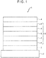
- FIG. 1 schematically shows an exemplary arrangement of the organic EL device according to the exemplary embodiment.
- An organic EL device (1) includes a light-transmissive substrate (2), an anode (3), a cathode (4), and an organic layer (10) provided between the anode (3) and the cathode (4).
- the organic layer (10) include a hole injecting layer (6), a hole transporting layer (7), an emitting layer (5), an electron transporting layer (8), and an electron injecting layer (9) which are laminated on the anode (3) in this order.
- the emitting layer of the organic EL device according to the present invention comprises a first compound and a second compound, wherein at least one of the first and the second compound is a compound of formula (I) according to the present invention.
- the first compound is a host compound and the second compound is an emitter compound.
- the first compound in the first embodiment is a delayed fluorescent compound (TADF host).
- the first compound is represented by a compound of formula (I).
- Delayed fluorescence (thermally activated delayed fluorescence) is explained in " ADACHI, Chihaya, ed., "Yuki Hando-tai no Debaisu Bussei (Device Physics of Organic Semiconductors)", Kodansha, pp. 261-268 .”
- ⁇ E 13 ⁇ E S1T1
- TADF thermally activated delayed fluorescence
- Fig. 10.38 in this literature illustrates an occurrence mechanism of the delayed fluorescence.
- the first compound of the exemplary embodiment is a compound exhibiting thermally activated delayed fluorescence caused by this mechanism. Occurrence of delayed fluorescence emission can be determined by transient PL (Photo Luminescence) measurement.
- the behavior of delayed fluorescence can be analyzed based on the decay curve obtained by the transient PL measurement.
- the transient PL measurement is a process where a sample is irradiated with a pulse laser to be excited, and a decay behavior (transient characteristics) of PL emission after the irradiation is stopped is measured.
- PL emission using a TADF material is divided into an emission component from singlet excitons generated by the first PL excitation and an emission component from singlet excitons generated via triplet excitons.
- the lifetime of the singlet excitons generated by the first PL excitation is in a nano-second order and considerably short. Emission from these singlet excitons thus decays immediately after the irradiation with the pulse laser.
- delayed fluorescence which is emission from the singlet excitons generated via long-life triplet excitons, decays slowly. There is thus a large difference in time between emission from the singlet excitons generated by the first PL excitation and emission from the singlet excitons generated via triplet excitons. Therefore, a luminous intensity resulting from the delayed fluorescence can be obtained.
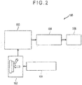
- Fig. 2 schematically shows an exemplary device for measuring transient PL.
- a transient PL measuring device 100 of the exemplary embodiment includes: a pulse laser 101 capable of emitting light with a predetermined wavelength; a sample chamber 102 configured to house a measurement sample; a spectrometer 103 configured to disperse light emitted from the measurement sample; a streak camera 104 configured to form a two-dimensional image; and a personal computer 105 configured to analyze the two-dimensional image imported thereinto. It should be noted that transient PL may be measured by a device different from one described in the exemplary embodiment.
- the sample to be housed in the sample chamber 102 is prepared by forming a thin film, which is made of a matrix material doped with a doping material at a concentration of 12 mass%, on a quartz substrate.
- the thus-obtained thin film sample is housed in the sample chamber 102, and is irradiated with a pulse laser emitted from the pulse laser 101 to excite the doping material.
- the emitted excitation light is taken in a 90-degree direction with respect to the irradiation direction of the excitation light, and is dispersed by the spectrometer 103.
- a two-dimensional image of the light is formed through the streak camera 104.
- an ordinate axis corresponds to time
- an abscissa axis corresponds to wavelength
- a bright spot corresponds to luminous intensity.
- the two-dimensional image is taken at a predetermined time axis, thereby obtaining an emission spectrum with an ordinate axis representing luminous intensity and an abscissa axis representing wavelength. Further, the two-dimensional image is taken at a wavelength axis, thereby obtaining a decay curve (transient PL) with an ordinate axis representing the logarithm of luminous intensity and an abscissa axis representing time.
- transient PL decay curve
- a thin film sample A was prepared using a reference compound M1 below as a matrix material and a reference compound DP1 below as a doping material, and transient PL was measured. Respective decay curves of the thin film sample A and a thin film sample B were analyzed.
- the thin film sample B was prepared in the same manner as described above using a reference compound M2 below as a matrix material and the reference compound DP1 as a doping material.
- Fig. 3 shows a decay curve obtained from transient PL measured using each of the thin film samples A and B.
- an emission decay curve with an ordinate axis representing luminous intensity and an abscissa axis representing time can be obtained by the transient PL measurement. Based on the emission decay curve, a fluorescence intensity ratio between fluorescence emitted from a singlet state generated by photo-excitation and delayed fluorescence emitted from a singlet state generated by inverse energy transfer via a triplet state can be estimated. In a delayed fluorescent material, a ratio of the intensity of the slowly decaying delayed fluorescence to the intensity of the promptly decaying fluorescence is relatively large.
- the luminescence amount of the delayed fluorescence can be obtained using the device shown in Fig. 2 .
- Emission from the first compound includes: Prompt emission observed immediately when the excited state is achieved by exciting the first compound with a pulse beam (i.e., a beam emitted from a pulse laser) having an absorbable wavelength; and Delay emission observed not immediately when but after the excited state is achieved.
- the amount of Delay emission is preferably 5% or more relative to the amount of Prompt emission.
- the amount of Prompt emission and the amount of Delay emission can be obtained in the same method as a method described in “ Nature 492, 234-238, 2012 ".
- the amount of Prompt emission and the amount of Delay emission may be calculated using a device different from one described in the above Literature.
- a sample usable for measuring the delayed fluorescence may be prepared by codepositing the first compound and a compound TH-2 below on a quartz substrate at a ratio of the first compound being 12 mass% to form a 100-nm-thick thin film.
- the second compound in the first embodiment is a fluorescent compound (emitter).
- the second compound preferably emits fluorescence having a main peak wavelength (occasionally referred to as an emission peak wavelength) of 430 to 780 nm (blue, green, red).
- the main peak wavelength means a peak wavelength of luminescence spectrum exhibiting a maximum luminous intensity among luminous spectra measured using a toluene solution where the second compound is dissolved at a concentration from 10 -6 mol/l to 10 -5 mol/l.
- the second compound preferably emits a red, green or blue fluorescence.
- the second compound is preferably a material exhibiting a high emission quantum efficiency.
- Suitable fluorescent emitters emitting a red, green or blue fluorescence are known to a person skilled in the art.
- Examples of the fluorescent emitter include a bisarylamino naphthalene derivative, an aryl-substituted naphthalene derivative, a bisarylamino anthracene derivative, an aryl-substituted anthracene derivative, a bisarylamino pyrene derivative, an aryl-substituted pyrene derivative, a bisarylamino chrysene derivative, an aryl-substituted chrysene derivative, a bisarylamino fluoranthene derivative, an aryl-substituted fluoranthene derivative, an indenoperylene derivative, a pyrromethene boron complex compound, a compound having a pyrromethene skeleton or a metal complex thereof, a diketopyrrolopyrrole derivative, and a perylene derivative.
- R 201 to R 212 are each independently a hydrogen atom or a substituent.
- R 201 to R 212 are a substituent
- the substituent is selected from the group consisting of a substituted or unsubstituted alkyl group having 1 to 30 carbon atoms, a substituted or unsubstituted aryl group having 6 to 30 ring carbon atoms, a substituted or unsubstituted heterocyclic group having 5 to 30 ring atoms, a substituted or unsubstituted alkoxy group having 1 to 30 carbon atoms, a substituted or unsubstituted aryloxy group having 6 to 30 ring carbon atoms, a substituted or unsubstituted aralkyl group having 6 to 30 ring carbon atoms, a substituted amino group, a cyano group and a halogen atom.
- the substituents of R 201 to R 212 may be mutually bonded to form a cyclic structure.
- X is a nitrogen atom or a carbon atom to be bonded to Y;
- Y is a hydrogen atom or a substituent;
- R 21 to R 26 are each independently a hydrogen atom or a substituent; when Y and R 21 to R 26 are substituents, the substituents are selected from the group consisting of a substituted or unsubstituted alkyl group, a substituted or unsubstituted cycloalkyl group, a substituted or unsubstituted aromatic hydrocarbon group, a substituted or unsubstituted alkoxy group, a substituted or unsubstituted alkylthio group, a substituted or unsubstituted aryloxy group, a substituted or unsubstituted arylthio group, a substituted or unsubstituted alkenyl group, a substituted or unsubstituted aralkyl group, a substituted or unsubstituted heterocyclic
- R 21 to R 26 in the formula (2) may be bonded to each other to form a cyclic structure.
- fluorescence emitters are for example described in WO 2017/146397 and US 20170141322 , especially the compounds of formula (4),
- the organic EL device in the first embodiment is capable of prolonging a lifetime, improving a luminous efficiency, and inhibiting a roll-off when driven at a high current density.
- the roll-off refers to a phenomenon in which a luminous efficiency is decreased when the organic EL device is driven at a high current density.
- the first compound contained in the emitting layer in the exemplary embodiment is a delayed fluorescent compound, a compound of formula (I). Since the delayed fluorescent compound has a donor (electron-donating) moiety and an acceptor (electron accepting) moiety in a molecular structure, electric charges exist in a localized state in a molecule of the delayed fluorescent compound when the delayed fluorescent compound is excited. Since such a localized state of the electric charges possibly causes various side reactions, the delayed fluorescent compound having a long excited lifetime tends to exhibit a low stability especially in the excited state. Moreover, a half bandwidth of the luminescence spectrum of the delayed fluorescent compound is increased. Accordingly, it is difficult to use the delayed fluorescent compound as a luminescent material for a display unit requiring a high definition display in a large-sized TV set and the like.
- an organic EL device including an emitting layer containing a delayed fluorescent compound and a fluorescent compound has been studied.
- the delayed fluorescent compound is used as a sensitizer in the emitting layer and the fluorescent compound is used as the luminescent material.
- the fluorescent compound since the fluorescent compound emits light, it is expected that the half bandwidth of the luminescence spectrum is decreased.
- emission from the delayed fluorescent compound having a low excitation stability can be avoided, it is expected that a lifetime of the organic EL device is prolonged.
- it is theoretically expected that the same luminous efficiency as that of an organic EL device including an emitting layer containing a delayed fluorescent compound as a luminescent material is obtained.
- the inventors have found that a combination of the delayed fluorescent compound that is the first compound and the fluorescent compound that is the second compound, wherein the first compound (delayed fluorescent compound (TADF host)) is a compound of formula (I) according to the present invention, can provide advantages of prolonging a lifetime, improving a luminous efficiency, and inhibiting a roll-off in a high current density region.
- the organic EL device in the first embodiment preferably emits light exhibiting a peak in a wavelength range of 430 to 780 nm.
- the main peak wavelength of the light emitted from the organic EL device preferably falls within a range of 430 to 780 nm.
- the second compound mainly emits light in the emitting layer (5).
- the wavelength range of the light emitted by the organic EL device in the first embodiment is more preferably from 430 nm to 570 nm.
- the organic EL device in the first embodiment emits blue or green fluorescence.
- the first compound is preferably a compound having a small ⁇ ST(M1) so that inverse intersystem crossing from the triplet energy level of the first compound to the singlet energy level thereof is easily caused by a heat energy given from the outside.
- An energy state conversion mechanism to perform spin exchange from the triplet state of electrically excited excitons within the organic EL device to the singlet state by inverse intersystem crossing is referred to as a TADF mechanism.
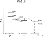
- Fig. 4 exemplarily shows a relationship in energy levels (EnL in Fig. 4 is the energy level) between the first compound (1 st ) and the second compound (2 nd ) in the emitting layer.
- S0 represents a ground state
- S1(M1) represents a lowest singlet state of the first compound
- T1(M1) represents a lowest triplet state of the first compound
- S1(M2) represents a lowest singlet state of the second compound
- T1(M2) represents a lowest triplet state of the second compound.
- a dashed arrow directed from S1(M1) to S1(M2) in Fig. 4 represents Forster energy transfer from the lowest singlet state of the first compound to the lowest singlet state of the second compound.
- a difference between the lowest singlet state S1 and the lowest triplet state T1 is defined as ⁇ ST.
- a singlet energy S(M1) of the first compound is preferably larger than a singlet energy S(M2) of the second compound.
- an energy gap T77K(M1) at 77[K] of the first compound is preferably larger than an energy gap T77K(M2) at 77[K] of the second compound.
- T77K(M1) is preferably 2.0 eV or more, more preferably 2.2 eV or more.
- the energy gap at 77 [K] is different from a typical triplet energy in some aspects.
- the triplet energy is measured as follows. Firstly, a target compound for measurement is deposited on a quartz substrate to prepare a sample. Alternatively, the target compound is dissolved in an appropriate solvent to prepare a solution and the solution is encapsulated in a quartz glass pipe to prepare a sample. A phosphorescent spectrum (ordinate axis: phosphorescent luminous intensity, abscissa axis: wavelength) of the sample is measured at a low temperature (77K). A tangent is drawn to the rise of the phosphorescent spectrum on the short-wavelength side. The triplet energy is calculated by a predetermined conversion equation based on a wavelength value at an intersection of the tangent and the abscissa axis.
- the first compound usable in the exemplary embodiment is preferably a compound having a small ⁇ ST.
- ⁇ ST is small, intersystem crossing and inverse intersystem crossing are likely to occur even at a low temperature (77K), so that the singlet state and the triplet state coexist.
- the spectrum to be measured in the same manner as the above includes emission from both the singlet state and the triplet state.
- the value of the triplet energy is basically considered dominant.
- the triplet energy is measured by the same method as a typical triplet energy T, but a value measured in the following manner is referred to as an energy gap T 77K in order to differentiate the measured energy from the typical triplet energy in a strict meaning.
- the target compound for the measurement is deposited at a film thickness of 100 nm on a quartz substrate to form a sample.
- a phosphorescent spectrum (ordinate axis: phosphorescent luminous intensity, abscissa axis: wavelength) of the sample is measured at a low temperature (77K).
- a tangent is drawn to the rise of the phosphorescent spectrum on the short-wavelength side.
- An energy amount is calculated by the following conversion equation 1 based on a wavelength value ⁇ edge [nm] at an intersection of the tangent and the abscissa axis and defined as an energy gap T 77K .
- T 77 K eV 1239.85 / ⁇ dge
- the tangent to the rise of the phosphorescence spectrum on the short-wavelength side is drawn as follows. While moving on a curve of the phosphorescence spectrum from the short-wavelength side to the maximum spectral value closest to the short-wavelength side among the maximum spectral values, a tangent is checked at each point on the curve toward the long-wavelength of the phosphorescence spectrum. An inclination of the tangent is increased as the curve rises (i.e., a value of the ordinate axis is increased). A tangent drawn at a point of the maximum inclination (i.e., a tangent at an inflection point) was defined as the tangent to the rise of the phosphorescence spectrum on the short-wavelength side.
- the maximum with peak intensity being 15% or less of the maximum peak intensity of the spectrum is not included in the above-mentioned maximum closest to the short-wavelength side of the spectrum.
- the tangent drawn at a point of the maximum spectral value being closest to the short-wavelength side and having the maximum inclination is defined as a tangent to the rise of the phosphorescence spectrum on the short-wavelength side.
- a spectrophotofluorometer body F-4500 (manufactured by Hitachi High-Technologies Corporation) is usable.
- the measurement instrument is not limited to this arrangement.
- a combination of a cooling unit, a low temperature container, an excitation light source and a light-receiving unit may be used for measurement.
- Example 2 the absorption spectrum was measured using a spectrophotometer manufactured by Hitachi, Ltd. (device name: U3310). It should be noted that the absorption spectrum measuring device may be different from the above device.
- the tangent to the fall of the absorption spectrum on the long-wavelength side is drawn as follows. While moving on a curve of the absorption spectrum from the maximum spectral value closest to the long-wavelength side in a long-wavelength direction, a tangent at each point on the curve is checked. An inclination of the tangent is decreased and increased in a repeated manner as the curve falls (i.e., a value of the ordinate axis is decreased). A tangent drawn at a point of the minimum inclination closest to the long-wavelength side (except when absorbance is 0.1 or less) is defined as the tangent to the fall of the absorption spectrum on the long-wavelength side.
- the maximum absorbance of 0.2 or less is not included in the above-mentioned maximum absorbance on the long-wavelength side.
- a film thickness of the emitting layer (5) of the organic EL device (1) of the exemplary embodiment is preferably in a range from 5 nm to 100 nm, more preferably in a range from 7 nm to 100 nm, and most preferably in a range from 10 nm to 100 nm.
- the thickness of less than 5 nm may cause difficulty in forming the emitting layer (5) and in controlling chromaticity, while the thickness of more than 100 nm may raise drive voltage.
- a content ratio of the first compound is preferably 5 mass% or more, more preferably in a range from 10 mass% to 80 mass%, further preferably in a range from 40 mass% to 60 mass%.
- a content ratio of the second compound is preferably in a range from 1 mass% to 10 mass%.
- An upper limit of the total of the respective content ratios of the first and second compounds in the emitting layer 5 is 100 mass%. It should be noted that the emitting layer 5 of the exemplary embodiment may further contain another material in addition to the first and second compounds.
- a substrate (2) is used as a support for the organic EL device (1).
- glass, quartz, plastics and the like are usable as the substrate (2).
- a flexible substrate is also usable.
- the flexible substrate is a bendable substrate.
- the flexible substrate is exemplified by a plastic substrate formed of polycarbonate, polyarylate, polyethersulfone, polypropylene, polyester, polyvinyl fluoride, polyvinyl chloride, polyimide, polyethylene naphthalate or the like.
- an inorganic vapor deposition film is also usable as the substrate (2).
- Metal, alloy, an electrically conductive compound, a mixture thereof and the like, which have a large work function (specifically, of 4.0 eV or more) is preferably usable as the anode (3) formed on the substrate (2).
- the material for the anode include indium tin oxide (ITO), indium tin oxide containing silicon or silicon oxide, indium zinc oxide, tungsten oxide, indium oxide containing zinc oxide and graphene.
- gold Au
- platinum Pt
- nickel Ni
- tungsten W
- chrome Cr
- molybdenum Mo
- iron Fe
- cobalt Co
- copper Cu
- palladium Pd
- titanium Ti
- nitrides of a metal material e.g., titanium nitride
- indium zinc oxide can be deposited as a film by sputtering using a target that is obtained by adding zinc oxide in a range from 1 mass% to 10 mass% to indium oxide.
- indium oxide containing tungsten oxide and zinc oxide can be deposited as a film by sputtering using a target that is obtained by adding tungsten oxide in a range from 0.5 mass% to 5 mass% and zinc oxide in a range from 0.1 mass% to 1 mass% to indium oxide.
- vapor deposition, coating, ink jet printing, spin coating and the like may be used for forming the anode (3).
- a hole injecting layer (6) formed adjacent to the anode (3) is formed of a composite material that facilitates injection of holes irrespective of the work function of the anode (3). Accordingly, a material usable as an electrode material (e.g., metal, alloy, an electrically conductive compound, a mixture thereof, and elements belonging to Groups 1 and 2 of the periodic table of the elements) is usable as the material for the anode (3).
- an electrode material e.g., metal, alloy, an electrically conductive compound, a mixture thereof, and elements belonging to Groups 1 and 2 of the periodic table of the elements
- the elements belonging to Groups 1 and 2 of the periodic table of the elements which are materials having a small work function, namely, an alkali metal such as lithium (Li) and cesium (Cs) and an alkaline earth metal such as magnesium (Mg), calcium (Ca) and strontium (Sr), alloy thereof (e.g., MgAg, AlLi), a rare earth metal such as europium (Eu) and ytterbium (Yb), and alloy thereof are also usable as the material for the anode.
- an alkali metal such as lithium (Li) and cesium (Cs)
- an alkaline earth metal such as magnesium (Mg), calcium (Ca) and strontium (Sr), alloy thereof (e.g., MgAg, AlLi)
- a rare earth metal such as europium (Eu) and ytterbium (Yb)
- alloy thereof e.g., MgAg, AlLi
- a rare earth metal such as euro
- a hole injecting layer (6) is a layer containing a highly hole-injectable substance.
- the highly hole-injectable substance include molybdenum oxide, titanium oxide, vanadium oxide, rhenium oxide, ruthenium oxide, chromium oxide, zirconium oxide, hafnium oxide, tantalum oxide, silver oxide, tungsten oxide, and manganese oxide.
- the examples of the highly hole-injectable substance further include: an aromatic amine compound, which is a low-molecule compound, such that 4,4',4"-tris(N,N-diphenylamino)triphenylamine (abbreviation: TDATA), 4,4',4"-tris[N-(3-methylphenyl)-N-phenylamino]triphenylamine (abbreviation: MTDATA), 4,4'-bis[N-(4-diphenylaminophenyl)-N-phenylamino]biphenyl(abbreviation: DPAB), 4,4'-bis(N- ⁇ 4-[N'-(3-methylphenyl)-N'-phenylamino]phenyl ⁇ -N-phenylamino)biphenyl (abbreviation: DNTPD), 1,3,5-tris[N-(4-diphenylaminophenyl)-N-phenylamino]benzene (abbreviation
- a high-molecule compound e.g., an oligomer, dendrimer and polymer
- the high-molecule compound include poly(N-vinylcarbazole) (abbreviation: PVK), poly(4-vinyltriphenylamine) (abbreviation: PVTPA), poly[N-(4- ⁇ N'-[4-(4-diphenylamino)phenyl]phenyl-N' -phenylamino ⁇ phenyl)methacrylamido] (abbreviation: PTPDMA), and poly[N,N'-bis(4-butylphenyl)-N,N'-bis(phenyl)benzidine] (abbreviation: Poly-TPD).
- PVK poly(N-vinylcarbazole)
- PVTPA poly(4-vinyltriphenylamine)
- PTPDMA poly[N-(4- ⁇ N'-[4-(4-diphenylamino)phenyl]
- the examples of the high-molecule compound include a high-molecule compound added with an acid such as poly(3,4-ethylene dioxythiophene)/poly(styrene sulfonic acid) (PEDOT/PSS), and polyaniline/poly(styrene sulfonic acid) (PAni/PSS).
- an acid such as poly(3,4-ethylene dioxythiophene)/poly(styrene sulfonic acid) (PEDOT/PSS), and polyaniline/poly(styrene sulfonic acid) (PAni/PSS).
- a hole transporting layer (7) is a layer containing a highly hole-transportable substance.
- An aromatic amine compound, carbazole derivative, anthracene derivative and the like are usable for the hole transporting layer (7).
- Specific examples of a material for the hole transporting layer 7 include 4,4'-bis[N-(1-naphthyl)-N-phenylamino]biphenyl (abbreviation: NPB), N,N'-bis(3-methylphenyl)-N,N'-diphenyl-[1,1'-biphenyl]-4,4'-diamine (abbreviation: TPD), 4-phenyl-4'-(9-phenylfluorene-9-yl)triphenylamine (abbreviation: BAFLP), 4,4'-bis[N-(9,9-dimethylfluorene-2-yl)-N-phenylamino]biphenyl (abbreviation: DFLDPBi
- a carbazole derivative such as CBP, 9-[4-(N-carbazolyl)]phenyl-10-phenyl anthracene (CzPA) and 9-phenyl-3-[4-(10-phenyl-9-anthryl)phenyl]-9H-carbazole (PCzPA); an anthracene derivative such as t-BuDNA, DNA, and DPAnth; and a high-molecular weight compound such as poly(N-vinylcarbazole)(abbreviation: PVK) and poly(4-vinyltriphenylamine)(abbreviation: PVTPA) are usable for the hole transporting layer (7).
- CBP 9-[4-(N-carbazolyl)]phenyl-10-phenyl anthracene
- PCzPA 9-phenyl-3-[4-(10-phenyl-9-anthryl)phenyl]-9H-carbazole
- an anthracene derivative such
- a highly hole-transportable substance may be provided in the form of a single layer or a laminated layer of two or more layers of the above substance.
- the hole transporting layer includes two or more layers
- one of the layers with a larger energy gap is preferably provided closer to the emitting layer (5).
- the hole transporting layer (7) preferably has a function of preventing triplet excitons generated in the emitting layer (5) from diffusing into the hole transporting layer to trap the triplet excitons within the emitting layer (5).
- An electron transporting layer (8) is a layer containing a highly electron-transportable substance.
- a metal complex such as an aluminum complex, beryllium complex and zinc complex
- heteroaromatic compound such as an imidazole derivative, benzimidazole derivative, azine derivative, carbazole derivative, and phenanthroline derivative
- 3) a high-molecule compound are usable.
- a metal complex such as Alq, tris(4-methyl-8-quinolinato)aluminum (abbreviation: Almq 3 ), bis(10-hydroxybenzo[h]quinolinato)beryllium (abbreviation: BeBq 2 ), BAlq, Znq, ZnPBO and ZnBTZ are usable.
- a heteroaromatic compound such as 2-(4-biphenyl)-5-(4-tert-butylphenyl)-1,3,4-oxadiazole (abbreviation: PBD), 1,3-bis[5-(ptert-butylphenyl)-1,3,4-oxadiazole-2-yl]benzene (abbreviation: OXD-7), 3-(4-tert-butylphenyl)-4-phenyl-5-(4-biphenyl)-1,2,4-triazole (abbreviation: TAZ), 3-(4-tert-butylphenyl)-4-(4-ethylphenyl)-5-(4-biphenyl)-1,2,4-triazole (abbreviation: p-EtTAZ), bathophenanthroline (abbreviation: BPhen), bathocuproine (abbreviation: BCP), and 4,4'-bis(5-methyl
- a benzimidazole compound is suitably usable.
- the above-described substances mostly have an electron mobility of 10 -6 cm 2 /(V•s) or more.
- any substance having an electron transporting performance higher than a hole transporting performance may be used for the electron transporting layer (8) in addition to the above substances.
- the electron transporting layer (8) may be provided in the form of a single layer or a laminated layer of two or more layers of the above substance(s).
- a high-molecule compound is also usable for the electron transporting layer (8).
- poly[(9,9-dihexylfluorene-2,7-diyl)-co-(pyridine-3,5-diyl)] (abbreviation: PF-Py)
- poly[(9,9-dioctylfluorene-2,7-diyl)-co-(2,2'-bipyridine-6,6'-diyl)] abbreviation: PF-BPy
- PF-BPy poly[(9,9-dioctylfluorene-2,7-diyl)-co-(2,2'-bipyridine-6,6'-diyl)]
- the hole transporting layer (8) preferably has a function of preventing triplet excitons generated in the emitting layer (5) from diffusing into the hole transporting layer (8) and the electron injecting layer (9) to trap the triplet excitons within the emitting layer (5).
- An electron injecting layer (9) is a layer containing a highly electron-injectable substance.
- a material for the electron injecting layer include an alkali metal, alkaline earth metal and a compound thereof, examples of which include lithium (Li), cesium (Cs), calcium (Ca), lithium fluoride (LiF), cesium fluoride (CsF), calcium fluoride (CaF2), and lithium oxide (LiOx).
- a substance obtained by containing an alkali metal, alkaline earth metal or a compound thereof in the electron transportable substance specifically, for instance, a substance obtained by containing magnesium (Mg) in Alq may be used. With this substance, electrons can be more efficiently injected from the cathode (4).
- a composite material provided by mixing an organic compound with an electron donor may be used for the electron injecting layer (9).
- the composite material exhibits excellent electron injecting performance and electron transporting performance since the electron donor generates electron in the organic compound.
- the organic compound is preferably a material exhibiting an excellent transforming performance of the generated electrons.
- the above-described substance for the electron transporting layer (8) e.g., the metal complex and heteroaromatic compound
- the electron donor may be any substance exhibiting an electron donating performance to the organic compound.
- an alkali metal, alkaline earth metal and a rare earth metal are preferable, examples of which include lithium, cesium, magnesium, calcium, erbium and ytterbium.
- an alkali metal oxide and alkaline earth metal oxide are preferable, examples of which include lithium oxide, calcium oxide, and barium oxide.
- Lewis base such as magnesium oxide is also usable.
- tetrathiafulvalene (abbreviation: TTF) is also usable.
- Metal, alloy, an electrically conductive compound, a mixture thereof and the like, which have a small work function, specifically, of 3.8 eV or less, is preferably usable as a material for the cathode (4).
- the material for the cathode 4 include: the elements belonging to Groups 1 and 2 of the periodic table of the elements, namely, an alkali metal such as litium (Li) and cesium (Cs) and an alkaline earth metal such as magnesium (Mg), calcium (Ca) and strontium (Sr); alloy thereof (e.g., MgAg, AlLi); a rare earth metal such as europium (Eu) and ytterbium (Yb); and alloy thereof.
- an alkali metal such as litium (Li) and cesium (Cs) and an alkaline earth metal such as magnesium (Mg), calcium (Ca) and strontium (Sr)
- alloy thereof e.g., MgAg, AlLi
- the cathode (4) is formed of the alkali metal, alkaline earth metal and alloy thereof, vapor deposition and sputtering are usable. Moreover, when the cathode (4) is formed of silver paste and the like, coating, ink jet printing and the like are usable.
- various conductive materials such as Al, Ag, ITO, graphene and indium tin oxide containing silicon or silicon oxide are usable for forming the cathode (4) irrespective of the magnitude of the work function.
- the conductive materials can be deposited as a film by sputtering, ink jet printing, spin coating and the like.
- each layer of the organic EL device (1) there is no restriction except for the above particular description for a method for forming each layer of the organic EL device (1) in the exemplary embodiment.
- Known methods such as dry film-forming and wet film-forming are applicable.
- the dry film-forming include vacuum deposition, sputtering, plasma and ion plating.
- the wet film-forming include spin coating, dipping, flow coating and ink-jet printing.
- the film thickness is typically preferably in a range of several nanometers to 1 ⁇ m because an excessively-thinned film is likely to cause defects such as a pin hole while an excessively-thickened film requires high voltage to be applied and deteriorates efficiency.
- the organic EL device (1) according to the first embodiment of the invention is usable in an electronic device such as a display unit and a light-emitting unit.
- the display unit include display components such as an organic EL panel module, TV, mobile phone, tablet, and personal computer.
- Examples of the light-emitting unit include an illuminator and a vehicle light.
- the present invention therefore further relates to an electronic device comprising the organic electroluminescence device according to the present application and the use of the compound of formula (I) according to the present invention in an electronic device.
- the organic EL device according to the second embodiment is different from the organic EL device according to the first embodiment in that the emitting layer comprises a first compound and a second compound, wherein the second compound is a delayed fluorescent compound (TADF emitter).
- the first compound is - in the second embodiment - not a delayed fluorescent compound.
- the second compound in the third embodiment is represented by a compound of formula (I).
- a combination of the delayed fluorescent compound that is the second compound and a host that is the first compound, wherein the second compound is a delayed fluorescent compound (TADF emitter) is a compound of formula (I) according to the present invention can provide advantages of prolonging a lifetime, improving a luminous efficiency, and inhibiting a roll-off in a high current density region.
- the organic EL device in the second embodiment preferably emits light exhibiting a peak in a wavelength range of 430 to 780 nm.
- the main peak wavelength of the light emitted from the organic EL device preferably falls within a range of 430 to 780 nm.
- the second compound mainly emits light in the emitting layer (5).
- the wavelength range of the light emitted by the organic EL device in the first embodiment is more preferably from 430 nm to 570 nm.
- the organic EL device in the first embodiment emits blue or green fluorescence.
- Host materials for TADF emitters are for example described in Chem. Soc. Rev 2017, 46, 915 (start page 974 ), Adv. Mater. 2017, 1605444, Volume 29, Issue 22, June 13, 2017 1605444 (Start page 39 ), J. Mater. Chem. C, 2016, 4, 11355-11381 (start page 11355 ), J. Mater. Chem. C, 2017,5, 8622-8653 .
- the first compound is a host compound, whereby suitable host compounds are known to a person skilled in the art.
- a content ratio of the first compound (host) is preferably 5 mass% or more, more preferably in a range from 10 mass% to 80 mass%, further preferably in a range from 40 mass% to 60 mass%.
- a content ratio of the second compound is preferably in a range from 1 mass% to 50 mass%.
- An upper limit of the total of the respective content ratios of the first and second compounds in the emitting layer (5) is 100 mass%. It should be noted that the emitting layer (5) of the exemplary embodiment may further contain another material in addition to the first and second compounds.
- the organic EL device according to the third embodiment is different from the organic EL device according to the first embodiment in that the emitting layer further includes a third compound.
- Other components are the same as those in the first embodiment.
- at least one compound of formula (I) is present as first (TADF host) compound.
- the singlet energy of the third compound is larger than the singlet energy of the first compound.
- Fig. 5 exemplarily shows a relationship in energy levels (EnL in Fig. 4 is the enery level) between the first compound (1 st ), the second compound (2 nd ) and the third compound (3 rd ) in the emitting layer.
- S0 represents a ground state
- S1(M1) represents the lowest singlet state of the first compound
- T1(M1) represents the lowest triplet state of the first compound
- S1(M2) represents the lowest singlet state of the second compound
- T1(M2) represents the lowest triplet state of the second compound
- S1(M3) represents a lowest singlet state of the third compound
- T1(M3) represents a lowest triplet state of the third compound.
- a dashed arrow directed from S1(M1) to S1(M2) in Fig. 5 represents Forster energy transfer from the lowest singlet state of the first compound to the lowest singlet state of the second compound.
- the content ratio of the first compound is in a range from 10 mass% to 80 mass%
- the content ratio of the second compound is in a range from 1 mass% to 10 mass%
- the content ratio of the third compound is in a range from 10 mass% to 80 mass%.
- the content ratio of the first compound is more preferably in a range from 20 mass% to 80 mass%, further preferably in a range from 40 mass% to 60 mass%.
- An upper limit of the total of the respective content ratios of the first to third compounds in the emitting layer is 100 mass%.
- the emitting layer of the exemplary embodiment may further contain another material in addition to the first to third compounds.
- the third compound is not particularly limited, the third compound is preferably a compound other than an amine compound.
- carbazole derivatives, dibenzofuran derivatives, Si containing derivatives, phosphorous oxide derivatives and dibenzothiophene derivatives are usable as the third compound.
- the third compound is not limited thereto.
- the third compound preferably has at least one of a partial structure represented by a formula (31) below and a partial structure represented by a formula (32) below in one molecule.
- Y 31 to Y 36 each independently represent a nitrogen atom or a carbon atom bonded to another atom in the molecule of the third compound.
- At least one of Y 31 to Y 36 is a carbon atom bonded to another atom in the molecule of the third compound.
- Y 41 to Y 48 each independently represent a nitrogen atom or a carbon atom bonded to another atom in the molecule of the third compound.
- At least one of Y 41 to Y 48 is a carbon atom bonded to another atom in the molecule of the third compound.
- X 3 represents a nitrogen atom, an oxygen atom or a sulfur atom.
- Y 41 to Y 48 are carbon atoms bonded to another atom in the molecule of the third compound and a ring structure is formed including the carbon atoms.
- the third compound is also preferably an aromatic hydrocarbon compound or an aromatic heterocyclic compound. It is also preferable that the third compound has no fused aromatic hydrocarbon ring in a molecule.
- the third compound may be prepared by a method described in WO 2012/153780 , WO 2013/038650 and EP 3 255 693 .
- the organic EL device in the third embodiment is capable of prolonging a lifetime, improving a luminous efficiency, and inhibiting a roll-off when driven at a high current density.
- the emitting layer of the organic EL device according to the third embodiment includes the delayed fluorescent first compound, the fluorescent second compound, and the third compound having a larger singlet energy than the first compound, whereby the luminous efficiency of the organic EL device is further improved. It is deduced that the luminous efficiency is improved because a carrier balance in the emitting layer is improved by containing the third compound.
- the emitting layer is not limited to a single layer, but may be provided by laminating a plurality of emitting layers.
- the organic EL device has the plurality of emitting layers, it is only required that at least one of the emitting layers contains the first and second compounds.
- the rest of the emitting layers may be a fluorescent emitting layer or a phosphorescent emitting layer with use of emission caused by electron transfer from the triplet state directly to the ground state.
- the organic EL device includes the plurality of emitting layers
- the plurality of emitting layers may be adjacent to each other, or provide a so-called tandem-type organic EL device in which a plurality of emitting units are layered through an intermediate layer.
- a blocking layer may be provided in contact with an anode-side or a cathode-side of the emitting layer.
- the blocking layer is preferably provided in contact with the emitting layer to block at least ones of holes, electrons and excitons.
- the blocking layer when the blocking layer is provided in contact with the cathode-side of the emitting layer, the blocking layer permits transport of electrons, but prevents holes from reaching a layer provided near the cathode (e.g., the electron transporting layer) beyond the blocking layer.
- the blocking layer is preferably interposed between the emitting layer and the electron transporting layer.
- the blocking layer When the blocking layer is provided in contact with the anode-side of the emitting layer, the blocking layer permits transport of holes, but prevents electrons from reaching a layer provided near the anode (e.g., the hole transporting layer) beyond the blocking layer.
- the blocking layer is preferably interposed between the emitting layer and the hole transporting layer.
- the blocking layer may be provided in contact with the emitting layer to prevent an excitation energy from leaking from the emitting layer into a layer in the vicinity thereof.
- Excitons generated in the emitting layer are prevented from moving into a layer provided near the electrode (e.g., the electron transporting layer and the hole transporting layer) beyond the blocking layer.
- the emitting layer and the blocking layer are preferably bonded to each other.
- reaction mixture was stirred under argon at 155 °C for 2 h.
- 1.5 g sodium cyanide in 5 ml water was added and the reaction mixture was stirred at 120 °C for 1 h.
- the product was poured on water and the product was filtered off. The product was washed with water.
- the product was decocted 2 times in 100 ml ethanol.
- the reaction mixture was poured on 100 ml methanol and the product was filtered off. The product was washed with methanol, water and again methanol.
- reaction mixture was cooled to room temperature, filtered and the residue was washed with water and methanol and dried at 80°C/125mbar overnight to yield 10.1g of crude product. It was dissolved in 400ml DMF at reflux, 10g silica were added, stirred for 15min and then filtered hot through Hyflo. The resulting solution was rotavaped down until a suspension formed, that was cooled to room temperature, filtered and washed with MeOH. The product was dried at 80°C/125mbar overnight to yield 9.1g (64.1%) of product as a white solid.
- the reference compound Ref. 1 was prepared as described in WO2017115596A1 .
- the PLQY was measured in the following manner
- Example Solvent PLQY ⁇ ST k RISC / s-1 Example 1 toluene 61 % 0.03 eV 3.91E+05 Reference Example1 toluene 47 % 0.13 eV 2.12E+05 Reference Example2 toluene 68 % 0.19 eV 8.76E+04
- the organic EL device was prepared and evaluated as follows.
- a glass substrate (size: 25 mm.times.75 mm.times.1.1 mm thick, manufactured by Geomatec Co., Ltd.) having an ITO transparent electrode (anode) was ultrasonic-cleaned in isopropyl alcohol for five minutes, and then UV/ozone-cleaned for 30 minutes.
- the film of ITO was 130 nm thick.
- the glass substrate having the transparent electrode line was cleaned, the glass substrate was mounted on a substrate holder of a vacuum evaporation apparatus.
- a compound HI was vapor-deposited on a surface of the glass substrate where the transparent electrode line was provided in a manner to cover the transparent electrode, thereby forming a 5-nm-thick hole injecting layer.
- the compound HT-1 was vapor-deposited on the hole injecting layer to form a 110-nm-thick first hole transporting layer on the HI film.
- the compound HT-2 was deposited on the first hole transporting layer to form a 15-nm-thick second hole transporting layer.
- the compound mCP was deposited on the first hole transporting layer to form a 5-nm-thick second hole transporting layer.
- the host compound H-1 (the first compound) and the dopant compound D-1 (the second compound) were co-deposited on the second hole transporting layer to form a 25-nm-thick emitting layer.
- a concentration of the compound D-1 in the emitting layer was given at 24 mass %.
- a compound HB was deposited on the emitting layer to form a 5-nm-thick blocking layer.
- a compound ET-1 was deposited on the blocking layer to form a 35-nm-thick electron transporting layer.
- LiF Lithium fluoride
- a metal aluminum (Al) was then deposited on the electron injecting electrode to form an 80-nm-thick metal Al cathode.
- a device arrangement of the organic EL device of Example 1 is shown in symbols as follows. ITO(130)/HI(5)/HT-1(110)/HT-2(15)/ mCP(5)/H-1: D-1 (25, 24%)/HB(5)/ET(35)/LiF(1)/AI(80)
- Numerals in parentheses represent the film thickness (unit: nm).
- the numerals in the form of percentage in parentheses indicate the ratio (mass %) of the second compound in the emitting layer (the sum of all components in the emitting layer is 100 wt%).
- Table 2 TADF-dopant Amount [wt%] V @10mA EQE @0.1mA EQE @10mA ⁇ p 1) @10mA Example 1 24 5.1 13.4 10.2 461 Reference Example 1 24 5.1 11.2 7.7 458 Reference Example 2 24 5.0 12.1 6.2 458 1) ⁇ p emission wavelength
- the PLQY photoluminescence quantum yield
- Example 2 An organic EL device of Example 2 was prepared in the same manner as the organic EL device of Example 1 except that a process for forming the emitting layer was changed as follows.
- the compound H-1 (the first compound), the compound BD(the second compound) and a compound CH-1 (the third compound) were co-deposited on the second hole transporting layer to form a 25-nm-thick emitting layer.
- the concentration of the compound BD in the emitting layer was given at 1 mass % and the concentration of the compound H-1 in the emitting layer was given at 50 mass %.
- a device arrangement of the organic EL device of Example 2 is shown in symbols as follows. ITO(130)/HI(5)/HT-1(110)/HT-2(15)/CH-1: H-1: BD (25, 50%, 1%)/HB(5)/ET(35)/LiF(1)/Al(80)
- Numerals in parentheses represent a film thickness (unit: nm).
- the numerals in the form of percentage in parentheses indicate the ratio (mass %) of the first compound and the ratio (mass %) of the second compound in the emitting layer.
- Table 4 TADF (Material) BD (Material) CIEx @10mA CIEy @10mA EQE @0.1mA EQE @10mA ⁇ p @10mA Reference Example 3 compound A 0.175 0.288 15.1 8.9 466
- the PLQY was measured in the following manner.
Landscapes
- Chemical & Material Sciences (AREA)
- Organic Chemistry (AREA)
- Electroluminescent Light Sources (AREA)
- Nitrogen Condensed Heterocyclic Rings (AREA)
Priority Applications (1)
| Application Number | Priority Date | Filing Date | Title |
|---|---|---|---|
| EP18180155.6A EP3587423A1 (de) | 2018-06-27 | 2018-06-27 | Organische verbindungen und diese enthaltende organische elektrolumineszenzvorrichtung |
Applications Claiming Priority (1)
| Application Number | Priority Date | Filing Date | Title |
|---|---|---|---|
| EP18180155.6A EP3587423A1 (de) | 2018-06-27 | 2018-06-27 | Organische verbindungen und diese enthaltende organische elektrolumineszenzvorrichtung |
Publications (1)
| Publication Number | Publication Date |
|---|---|
| EP3587423A1 true EP3587423A1 (de) | 2020-01-01 |
Family
ID=62814879
Family Applications (1)
| Application Number | Title | Priority Date | Filing Date |
|---|---|---|---|
| EP18180155.6A Withdrawn EP3587423A1 (de) | 2018-06-27 | 2018-06-27 | Organische verbindungen und diese enthaltende organische elektrolumineszenzvorrichtung |
Country Status (1)
| Country | Link |
|---|---|
| EP (1) | EP3587423A1 (de) |
Cited By (2)
| Publication number | Priority date | Publication date | Assignee | Title |
|---|---|---|---|---|
| WO2022131344A1 (ja) * | 2020-12-17 | 2022-06-23 | 出光興産株式会社 | 有機エレクトロルミネッセンス素子及び電子機器 |
| US11482681B2 (en) | 2018-07-27 | 2022-10-25 | Idemitsu Kosan Co., Ltd. | Compound, material for organic electroluminescence element, organic electroluminescence element, and electronic device |
Citations (13)
| Publication number | Priority date | Publication date | Assignee | Title |
|---|---|---|---|---|
| WO2012153780A1 (ja) | 2011-05-11 | 2012-11-15 | 出光興産株式会社 | 新規化合物、有機エレクトロルミネッセンス素子用材料及び有機エレクトロルミネッセンス素子 |
| WO2013038650A1 (ja) | 2011-09-13 | 2013-03-21 | 出光興産株式会社 | 縮合複素芳香族誘導体、有機エレクトロルミネッセンス素子用材料及びそれを用いた有機エレクトロルミネッセンス素子 |
| US20160172601A1 (en) | 2014-12-12 | 2016-06-16 | Idemitsu Kosan Co., Ltd. | Organic electroluminescent element and electronic device |
| US20160190469A1 (en) | 2014-10-07 | 2016-06-30 | Idemitsu Kosan Co., Ltd. | Organic electroluminescence device and electronic device |
| WO2016157113A1 (en) | 2015-03-31 | 2016-10-06 | Idemitsu Kosan Co., Ltd. | Benzimidazolo[1,2-a]benzimidazole carrying aryl- or heteroarylnitril groups for organic light emitting diodes |
| EP3109253A1 (de) | 2014-02-18 | 2016-12-28 | Kwansei Gakuin Educational Foundation | Polycyclische aromatische verbindung |
| WO2017056052A1 (en) | 2015-10-01 | 2017-04-06 | Idemitsu Kosan Co., Ltd. | Benzimidazolo[1,2-a]benzimidazole carrying benzimidazolo[1,2-a]benzimidazolyl groups, carbazolyl groups, benzofurane groups or benzothiophene groups for organic light emitting diodes |
| US20170141322A1 (en) | 2015-11-13 | 2017-05-18 | Sfc Co., Ltd. | Novel amine compounds for organic light-emitting diode and organic light-emitting diode including the same |
| WO2017093958A1 (en) | 2015-12-04 | 2017-06-08 | Idemitsu Kosan Co., Ltd. | Benzimidazolo[1,2-a]benzimidazole derivatives for organic light emitting diodes |
| WO2017115596A1 (ja) | 2015-12-28 | 2017-07-06 | 新日鉄住金化学株式会社 | 有機電界発光素子 |
| KR20170081438A (ko) | 2016-01-04 | 2017-07-12 | 삼성에스디아이 주식회사 | 유기 화합물, 유기 광전자 소자 및 표시 장치 |
| WO2017146397A1 (ko) | 2016-02-22 | 2017-08-31 | 에스에프씨 주식회사 | 신규한 아민 화합물 및 이를 포함하는 유기 발광 소자 |
| EP3255693A1 (de) | 2015-02-06 | 2017-12-13 | Idemitsu Kosan Co., Ltd | Organisches elektrolumineszentes element und elektronische vorrichtung |
-
2018
- 2018-06-27 EP EP18180155.6A patent/EP3587423A1/de not_active Withdrawn
Patent Citations (13)
| Publication number | Priority date | Publication date | Assignee | Title |
|---|---|---|---|---|
| WO2012153780A1 (ja) | 2011-05-11 | 2012-11-15 | 出光興産株式会社 | 新規化合物、有機エレクトロルミネッセンス素子用材料及び有機エレクトロルミネッセンス素子 |
| WO2013038650A1 (ja) | 2011-09-13 | 2013-03-21 | 出光興産株式会社 | 縮合複素芳香族誘導体、有機エレクトロルミネッセンス素子用材料及びそれを用いた有機エレクトロルミネッセンス素子 |
| EP3109253A1 (de) | 2014-02-18 | 2016-12-28 | Kwansei Gakuin Educational Foundation | Polycyclische aromatische verbindung |
| US20160190469A1 (en) | 2014-10-07 | 2016-06-30 | Idemitsu Kosan Co., Ltd. | Organic electroluminescence device and electronic device |
| US20160172601A1 (en) | 2014-12-12 | 2016-06-16 | Idemitsu Kosan Co., Ltd. | Organic electroluminescent element and electronic device |
| EP3255693A1 (de) | 2015-02-06 | 2017-12-13 | Idemitsu Kosan Co., Ltd | Organisches elektrolumineszentes element und elektronische vorrichtung |
| WO2016157113A1 (en) | 2015-03-31 | 2016-10-06 | Idemitsu Kosan Co., Ltd. | Benzimidazolo[1,2-a]benzimidazole carrying aryl- or heteroarylnitril groups for organic light emitting diodes |
| WO2017056052A1 (en) | 2015-10-01 | 2017-04-06 | Idemitsu Kosan Co., Ltd. | Benzimidazolo[1,2-a]benzimidazole carrying benzimidazolo[1,2-a]benzimidazolyl groups, carbazolyl groups, benzofurane groups or benzothiophene groups for organic light emitting diodes |
| US20170141322A1 (en) | 2015-11-13 | 2017-05-18 | Sfc Co., Ltd. | Novel amine compounds for organic light-emitting diode and organic light-emitting diode including the same |
| WO2017093958A1 (en) | 2015-12-04 | 2017-06-08 | Idemitsu Kosan Co., Ltd. | Benzimidazolo[1,2-a]benzimidazole derivatives for organic light emitting diodes |
| WO2017115596A1 (ja) | 2015-12-28 | 2017-07-06 | 新日鉄住金化学株式会社 | 有機電界発光素子 |
| KR20170081438A (ko) | 2016-01-04 | 2017-07-12 | 삼성에스디아이 주식회사 | 유기 화합물, 유기 광전자 소자 및 표시 장치 |
| WO2017146397A1 (ko) | 2016-02-22 | 2017-08-31 | 에스에프씨 주식회사 | 신규한 아민 화합물 및 이를 포함하는 유기 발광 소자 |
Non-Patent Citations (10)
| Title |
|---|
| "Thermally Activated Delayed Fluorescence", ADV. MATER., vol. 26, 2014, pages 7931 - 7958 |
| "Yuki Hando-tai no Debaisu Bussei (Device Physics of Organic Semiconductors", 22 March 2012, KODANSHA, pages: 261 - 262 |
| "Yuki Hando-tai no Debaisu Bussei (Device Physics of Organic Semiconductors", pages: 261 - 268 |
| ADV. MATER., vol. 29, no. 22, 13 June 2017 (2017-06-13), pages 1605444 |
| ADVANCED MATERIALS (WEINHEIM, GERMANY, vol. 28, no. 14, 2016, pages 2777 - 2781 |
| CHEM. SOC. REV, vol. 46, 2017, pages 915 |
| HAJIME NAKANOTANI ET AL.: "High-Efficiency organic light-emitting diodes with fluorescent emitters", NATURE COMMUNICATIONS, vol. 5, 30 May 2014 (2014-05-30), pages 4016 |
| J. MATER. CHEM. C, vol. 4, 2016, pages 11355,11381 |
| J. MATER. CHEM. C, vol. 5, 2017, pages 8622 - 8653 |
| NATURE, vol. 492, 2012, pages 234 - 238 |
Cited By (2)
| Publication number | Priority date | Publication date | Assignee | Title |
|---|---|---|---|---|
| US11482681B2 (en) | 2018-07-27 | 2022-10-25 | Idemitsu Kosan Co., Ltd. | Compound, material for organic electroluminescence element, organic electroluminescence element, and electronic device |
| WO2022131344A1 (ja) * | 2020-12-17 | 2022-06-23 | 出光興産株式会社 | 有機エレクトロルミネッセンス素子及び電子機器 |
Similar Documents
| Publication | Publication Date | Title |
|---|---|---|
| EP3605636B1 (de) | Organisches elektrolumineszenzelement und elektronische vorrichtung | |
| EP2625171B1 (de) | Phenanthro[9,10-b]furane für elektronische anwendungen | |
| EP3276697A1 (de) | Organisches elektrolumineszenzelement, elektronische vorrichtung und verbindung | |
| EP3255693B1 (de) | Organisches elektrolumineszentes element und elektronische vorrichtung | |
| US12486452B2 (en) | Organic electroluminescent element and electronic device | |
| KR102385133B1 (ko) | 헤테로고리 화합물 및 이를 포함하는 유기 발광 소자 | |
| KR102810054B1 (ko) | 유기 일렉트로루미네센스 소자, 화합물, 유기 일렉트로루미네센스 소자용 재료, 및 전자 기기 | |
| US20220388991A1 (en) | Compound, material for organic electroluminescent element, organic electroluminescent element, and electronic device | |
| CN114127979B (zh) | 有机电致发光元件以及电子设备 | |
| CN114364686A (zh) | 包含吡咯亚甲基硼络合物的发光元件材料、发光元件、显示装置及照明装置 | |
| EP3974433B1 (de) | Organisches elektrolumineszentes element, verbindung und elektronisches gerät | |
| EP4310931A1 (de) | Organisches elektrolumineszenzelement, verbindung und elektronische vorrichtung | |
| US20240306499A1 (en) | Organic electroluminescence element and electronic device | |
| EP4141011B1 (de) | Verbindung, material für ein organisches elektrolumineszierendes element, organisches elektrolumineszierendes element und elektronische vorrichtung | |
| EP3587423A1 (de) | Organische verbindungen und diese enthaltende organische elektrolumineszenzvorrichtung | |
| EP3651225A1 (de) | Neuartige organische verbindungen und organische elektrolumineszenzvorrichtung damit | |
| US12289995B2 (en) | Compound, material for organic electroluminescent element, organic electroluminescent element and electronic device | |
| JP2024528864A (ja) | 光電子素子用有機分子 | |
| US20230301188A1 (en) | Organic electroluminescent element, organic electroluminescent light-emitting device, and electronic equipment | |
| US20190245152A1 (en) | Organic electroluminescence device and electronic device | |
| US20230371373A1 (en) | Organic electroluminescent element, compound, material for organic electroluminescent element, and electronic device | |
| JP2024526680A (ja) | 光電子素子用有機分子 | |
| JP2024517649A (ja) | 光電子素子用有機分子 | |
| KR20240000458A (ko) | 광전자 소자용 유기 분자 | |
| KR102306986B1 (ko) | 헤테로고리 화합물 및 이를 포함하는 유기 발광 소자 |
Legal Events
| Date | Code | Title | Description |
|---|---|---|---|
| PUAI | Public reference made under article 153(3) epc to a published international application that has entered the european phase |
Free format text: ORIGINAL CODE: 0009012 |
|
| AK | Designated contracting states |
Kind code of ref document: A1 Designated state(s): AL AT BE BG CH CY CZ DE DK EE ES FI FR GB GR HR HU IE IS IT LI LT LU LV MC MK MT NL NO PL PT RO RS SE SI SK SM TR |
|
| AX | Request for extension of the european patent |
Extension state: BA ME |
|
| STAA | Information on the status of an ep patent application or granted ep patent |
Free format text: STATUS: THE APPLICATION IS DEEMED TO BE WITHDRAWN |
|
| 18D | Application deemed to be withdrawn |
Effective date: 20200702 |