EP3587659A1 - Appareil d'acheminement d'eau électroménager - Google Patents
Appareil d'acheminement d'eau électroménager Download PDFInfo
- Publication number
- EP3587659A1 EP3587659A1 EP19180143.0A EP19180143A EP3587659A1 EP 3587659 A1 EP3587659 A1 EP 3587659A1 EP 19180143 A EP19180143 A EP 19180143A EP 3587659 A1 EP3587659 A1 EP 3587659A1
- Authority
- EP
- European Patent Office
- Prior art keywords
- condenser
- collector
- annular gap
- tube
- additional volume
- Prior art date
- Legal status (The legal status is an assumption and is not a legal conclusion. Google has not performed a legal analysis and makes no representation as to the accuracy of the status listed.)
- Granted
Links
Images


Classifications
-
- A—HUMAN NECESSITIES
- A47—FURNITURE; DOMESTIC ARTICLES OR APPLIANCES; COFFEE MILLS; SPICE MILLS; SUCTION CLEANERS IN GENERAL
- A47L—DOMESTIC WASHING OR CLEANING; SUCTION CLEANERS IN GENERAL
- A47L15/00—Washing or rinsing machines for crockery or tableware
- A47L15/42—Details
- A47L15/4291—Recovery arrangements, e.g. for the recovery of energy or water
-
- D—TEXTILES; PAPER
- D06—TREATMENT OF TEXTILES OR THE LIKE; LAUNDERING; FLEXIBLE MATERIALS NOT OTHERWISE PROVIDED FOR
- D06F—LAUNDERING, DRYING, IRONING, PRESSING OR FOLDING TEXTILE ARTICLES
- D06F39/00—Details of washing machines not specific to a single type of machines covered by groups D06F9/00 - D06F27/00
- D06F39/04—Heating arrangements
-
- Y—GENERAL TAGGING OF NEW TECHNOLOGICAL DEVELOPMENTS; GENERAL TAGGING OF CROSS-SECTIONAL TECHNOLOGIES SPANNING OVER SEVERAL SECTIONS OF THE IPC; TECHNICAL SUBJECTS COVERED BY FORMER USPC CROSS-REFERENCE ART COLLECTIONS [XRACs] AND DIGESTS
- Y02—TECHNOLOGIES OR APPLICATIONS FOR MITIGATION OR ADAPTATION AGAINST CLIMATE CHANGE
- Y02B—CLIMATE CHANGE MITIGATION TECHNOLOGIES RELATED TO BUILDINGS, e.g. HOUSING, HOUSE APPLIANCES OR RELATED END-USER APPLICATIONS
- Y02B30/00—Energy efficient heating, ventilation or air conditioning [HVAC]
- Y02B30/52—Heat recovery pumps, i.e. heat pump based systems or units able to transfer the thermal energy from one area of the premises or part of the facilities to a different one, improving the overall efficiency
Definitions
- the invention relates to a water-carrying household appliance, in particular a dishwasher, with a cleaning container, in particular a washing container, which provides a cleaning space, in particular a washing compartment, for holding items to be cleaned, for example items to be cleaned, a loading device, in particular spraying device, for loading items to be cleaned with a cleaning liquor and with a heat pump device for heating cleaning liquor, the heat pump device having a condenser and a collector.
- the one from the EP 2 682 039 A1 Previously known dishwasher has a rinsing container that provides a rinsing space. This is accessible on the user side via a loading opening which can be closed in a fluid-tight manner by means of a pivotably mounted washroom door.
- the washing container serves to hold items to be cleaned, which can be, for example, dishes, cutlery items and / or the like.
- the dishwasher has a spray device in the interior of the washing container to apply washing liquid, the so-called washing liquor, to items to be washed.
- This spray device typically provides rotatably mounted spray arms, usually two or three such spray arms being provided. In the intended use, the washware to be cleaned is loaded with wash liquor by means of rotating spray arms.
- the one from the EP 2 682 039 A1 previously known dishwasher also has via a heat pump device for heating the washing liquor, and this for the purpose of reducing the energy consumption of the dishwasher, in particular when heating the washing liquor, in particular because such heating of the washing liquor accounts for the largest part of the energy consumption of a dishwasher.
- the heat pump device has an evaporator, a compressor, a condenser, a collector, an expansion element in the form of a throttle and a flow circuit connecting these components.
- the heat pump device of the dishwasher after EP 2 682 039 A1 is an air-water heat pump device.
- the heat pump device extracts heat energy from the ambient atmosphere, that is to say from the air surrounding the dishwasher, in order to transfer it to the washing liquor circulated inside the dishwasher.
- the condenser of the heat pump device serves as a heat exchanger, by means of which heat energy is transferred from a working medium circulated in the flow circuit of the heat pump device to the washing liquor.
- water-water heat pump devices are also known from the prior art, for example from EP 2 206 824 A2 .
- a heat pump device does not extract thermal energy from the ambient atmosphere, but rather from a liquid reservoir.
- a water tank filled with water, for example, which houses the evaporator of the heat pump device can serve as the liquid reservoir.
- there is a cooling of the im due to thermal energy withdrawal Tank of stored water whereby the water can be cooled down to icing.
- a generic household appliance is proposed with the invention, which is characterized in that the condenser and the collector are combined to form a component.
- the condenser and the collector of the heat pump device are each formed as separate components which, in the final assembled state, are connected to one another in terms of flow technology via corresponding conduit paths.
- the embodiment according to the invention proposes to constructively combine the condenser and the collector with one another and to form them into one component.
- This configuration according to the invention has the advantage of simplified handling during production, since it is no longer necessary to maintain and install only two components. In particular, there is no soldering process for the fluidic connection of the collector and the condenser an appropriate route.
- the combination of condenser and collector according to the invention also has the advantage that the installation space to be provided for the heat pump device is reduced, which enables an optimized use of the available installation space. Due to the elimination of previously to be provided soldering points for fluidic connection of the condenser and collector, the number of potential leakage points is reduced, which increases operational reliability in an advantageous manner.
- the one-piece construction of the condenser and collector is preferably achieved in that the collector is designed as an integral part of the condenser.
- a condenser known per se from the prior art is expanded according to the invention by the function of the collector.
- This additional volume therefore serves as a collector volume, with which the collector is designed as an integral part of the condenser.
- the condenser is designed as a heat exchanger and, according to a further feature of the invention, has two tubes which are arranged coaxially with one another while leaving an annular gap space, the inner tube surrounded by the annular gap space being subjected to cleaning liquor, that is to say a rinsing liquor, and the annular gap space provided by the outer tube being subjected to refrigerant are.
- the condenser of the heat pump device is designed as a coaxial heat exchanger. It has a first pipe, the so-called cleaning liquor pipe or rinsing liquor pipe, through which the cleaning liquor or rinsing liquor originating from the cleaning room or rinsing room of the household appliance or the dishwasher is guided in the intended use.
- the so-called refrigerant tube is provided as the second tube, through which the working medium of the heat pump device, also referred to as refrigerant, is guided in the intended use.
- the first tube that is, the washing liquor tube, is arranged inside the refrigerant tube, with which the washing liquor tube forms the inner tube and the refrigerant tube forms the outer tube.
- the inner tube has an outer diameter which is less than the inner diameter of the outer tube, so that the two tubes are arranged coaxially with one another, leaving an annular gap space.
- the coaxial heat exchanger that is to say the liquefier of cleaning liquor or rinsing liquor on the one hand and the working medium on the other hand, is flowed through, preferably in countercurrent.
- the tube wall of the inner tube that is to say the cleaning liquor tube or rinsing liquor tube, serves as the interaction surface, via which a heat exchange takes place between the cleaning liquor and the working medium.
- the tubes of the coaxial heat exchanger can be designed to be straight or, for example, bent to form loops.
- the effective length of the pipes is between 0.5 m and 3 m, for example 2.20 m, 2.40 m or the like.
- the two tubes are matched to one another in such a way that the annular gap has a gap dimension, depending on the application, of between 0.15 mm and 1 mm, preferably between 0.3 mm and 0.8 mm, more preferably from 0. 5 mm.
- the annular gap space opens into an additional volume serving as a collector volume.
- an additional volume is provided which is in fluid communication with the annulus volume by opening into the additional volume.
- the working medium of the heat pump device which passes through the annular gap of the condenser in the intended process cycle, thus reaches the additional volume after flowing through the annular gap, in which the working medium can be temporarily stored if necessary before being forwarded to the evaporator.
- the additional volume serves as a collector volume.
- the additional volume is provided by the outer tube of the coaxial heat exchanger, that is to say the condenser.
- the outer tube has a section running in the longitudinal direction of the tube with one in comparison to the rest Inner diameter has increased inner diameter. Accordingly, an outer tube is provided which has a radial bulge. In the area of this radial bulge, an enlarged annular gap space is created due to the bulge, which creates the additional volume.
- the additional or collector volume is between 15 cm 3 and 55 cm 3 , preferably between 25 cm 3 and 45 cm 3 , more preferably 35 cm 3 . Accordingly, the inner diameter of the outer tube in the region of the radial extension and / or the length of the radial extension in the longitudinal direction of the tube are to be designed.
- the outer tube is provided with a radial bulge extending in the longitudinal direction of the tube.
- a plurality of such radial bulges are preferably provided, which are preferably arranged uniformly distributed in the circumferential direction of the tube.
- an outer tube is proposed which provides an outer contour that deviates from the circular shape. The distance to the inner tube received by the outer tube is increased in the area of the radial bulges, which in total creates the additional volume serving as the collector volume.
- the outer pipe carries a pipe socket that provides the additional volume.
- This pipe socket cooperates with a flow opening provided by the outer pipe, which provides the fluidic connection of the additional volume provided by the pipe socket to the annular gap space.
- a plurality of pipe sockets of the above type can be provided, which are preferably arranged one behind the other in the pipe longitudinal direction on the outer pipe.
- Each pipe socket provides part of the additional volume, so that the additional volume serving as the collector volume is created in total of all partial volumes.
- the pipe socket is radially aligned with the outer pipe. This orientation is particularly preferred for reasons of simplified production.
- the collector is omitted as an additional component, which improves storage, production and operational reliability.
- the manufacturing step of soldering is omitted, which minimizes the manufacturing outlay and reduces the number of possible leakage points.
- Different sized annular gap dimensions can be provided over the length of the condenser designed as a coaxial heat exchanger in the longitudinal direction, whereby the heat transfer on the refrigerant side can be increased in sections or the pressure loss on the refrigerant side can be reduced. This leads to a higher efficiency of the heat pump device or to a reduction in the size.
- the condenser has an annular gap space with a first dimension in a section located in the flow direction of the working medium upstream of the collector or the additional volume, and an annular gap chamber with a second dimension in a section located behind the collector or the additional volume in the flow direction of the working medium.
- the first dimension and the second dimension are between 0.15mm and 1mm.
- the first dimension and the second dimension can be the same size.
- the second dimension is preferably different from the first dimension, preferably smaller.
- the first dimension can be, for example, between 0.4 mm and 1 mm and the second dimension between 0.15 mm and 0.4 mm, in particular approximately 0.2 mm.
- the condenser points in the direction of flow of the working medium in front of the collector or the additional volume has a first section with a first annular gap dimension and a second section arranged between the first section and the collector or the additional volume with a second ring gap dimension different from the first.
- the second annulus dimension is preferably smaller than the first annulus dimension.
- the first annular gap dimension can be, for example, between 0.6 mm and 0.8 mm, while the second annular gap dimension can be, for example, between 0.3 mm and 0.5 mm.
- the condenser can have a further section located in the flow direction of the working medium behind the collector or the additional volume, with an even smaller annular gap dimension compared to the second annular gap dimension, which is preferably between 0.15 mm and 0.4 mm, for example around 0.2 mm lies.
- Dishwashers, washing machines, washer-dryers and / or similar devices are particularly suitable as water-carrying household appliances for which the configuration according to the invention can be used.
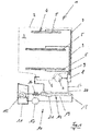
- Fig. 14 shows in a purely schematic representation a water-carrying household appliance in the configuration of a dishwasher 1 known per se from the prior art.
- the exemplary in Fig. 14 Dishwasher 1 shown has a washing compartment 2 which provides a washing compartment 3.
- the wash cabinet 3 serves to hold the items to be cleaned and in Fig. 14 Dishwashing goods, not shown.
- a spray device 4 which is arranged inside the washing container 2, serves as the loading device for loading washware to be cleaned with washing liquor.
- the spray device 4 has a total of three spray arms 5, which are each arranged rotatably within the washing container 2.
- the wash cabinet 3 opens into one in detail Fig. 14 A collection pot 6, not shown, of the washing compartment 2, to which a circulating pump 7 is connected in terms of flow.
- the spray arms 5 of the spray device 4 are connected in terms of flow technology to the circulating pump 7 by means of the feed lines 9 with the interposition of the water switch 8. In the intended use, the spray arms 5 can be loaded with rinsing liquor by means of the circulation pump 7.
- the dishwasher 1 also has a heat pump device 10. This has an evaporator 12, a compressor 13, a condenser 14, a collector 15, an expansion element in the form of a throttle 16 and a line 18 connecting these structural components in terms of flow technology, through which a Working or refrigerant or medium is performed.
- the evaporator 12 is arranged inside a tank 11 which is filled with a heat transfer medium, which is preferably water.
- the condenser 14 is used to transfer heat from the working medium through the line 18 of the heat pump device 10 to the washing liquor.
- a line 17, which is connected to the circulation pump 7 in terms of flow technology, is provided, which is used for the circulation of the washing liquor. The heat energy released in the condenser 14 by liquefaction of the working medium is therefore transferred to the rinsing liquor led through the line 17 in the circulating mode.
- the condenser 14 is designed as a coaxial heat exchanger and has two tubes which are arranged coaxially with one another leaving an annular gap space.
- the inner tube serves as a washing liquor tube which is connected to line 17.
- the outer tube surrounding the inner tube serves as a refrigerant tube and is connected to the line 18 of the heat pump device 10. When operating as intended, the working fluid flows through the annular gap and the washing liquor is guided through the inner tube.
- the condenser 14 has a collector 15 connected downstream in terms of flow.
- This collector 15 provides a buffer volume which serves to be able to temporarily store liquefied working fluid in the liquefier 14 before it continues in the course of another process cycle via the throttle 16 for re-evaporation to the evaporator 12.
- the invention proposes that the condenser 14 and the collector 15 be combined to form a component.
- This embodiment according to the invention is in Fig. 1 shown.
- Fig. 1 shows a dishwasher 1 designed according to the invention which, in contrast to a dishwasher 1 according to the prior art Fig. 14 has a condenser 14 which has a collector 21 as an integral part.
- the design of the condenser 14 and the collector 21 combined into one component offers the particular advantage that the manufacture is simplified overall by simplified handling and is therefore more cost-effective.
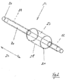
- the condenser 14 designed in the manner according to the invention is in different embodiments in the others Figures 2 to 13 shown.
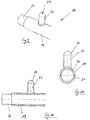
- the condenser 14 is designed as a coaxial heat exchanger and has two tubes, namely an inner tube 20 on the one hand and an outer tube 19 on the other.
- the two tubes 19 and 20 are arranged coaxially with one another, leaving an annular gap 22.
- the inner tube 20 serves for the passage of washing liquor
- the outer tube 19 receiving the inner tube 20 serving for the passage of a refrigerant, in countercurrent to the washing liquor, as is shown in FIG Figure 3 indicated arrows 25 and 26.
- the arrows 26 represent the flow direction for the refrigerant and the arrow 25 the flow direction for the washing liquor.
- the condenser 14 is set Additional volume 23 ready, which opens into the annular gap 22, as can be seen, for example, from a first embodiment Fig. 2 results.
- the additional volume 23 is formed by a section 28 of the outer pipe 19 which extends in the longitudinal direction 27 of the pipe and which has an enlarged inner diameter in comparison to the remaining inner diameter.
- the outer tube 19 therefore has a radial widening in the region of the section 28, as a result of which the additional volume 23 serving as the collector volume is created.
- Fig. 3 shows one too Fig. 2 similar embodiment.
- a standing arrangement of the condenser 14 is shown here, so that, in the intended operating case, liquefied working medium collects in the additional volume 23 in accordance with the level 24.
- successive pipe areas with different dimensions for the annular gap 22 are provided.
- a third area III with an annular gap of, for example, 0.2 mm are provided.
- These different annular gaps serve in particular to optimize the total amount of refrigerant required, taking into account the fact that smaller annular gaps can be provided for areas in which the refrigerant has an increased density.
- the refrigerant has the highest density, in particular in region III, since it is already liquefied in the direction of flow 25.
- the collector volume provided by the collector 21, that is to say the additional volume 23 of the outer tube 19, serves to compensate for different operating states of the heat pump device 10. Because the fill levels of the evaporator are often very different in the intended use, the collector 21 preventing a backflow of liquefied refrigerant in the condenser, which otherwise leads to a sharp increase in the high pressure and possibly. could lead to lockout.
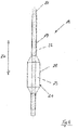
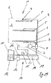
- FIG. 4 and 5 An alternative embodiment of the condenser according to the invention is shown in Figures 4 and 5 , In this embodiment, in contrast to the previously described embodiments, there is a section 28 which is longer in the longitudinal direction 27 of the tube intended. Due to the longer design of the section 28, with the additional volume 23 provided identically, the inside diameter of the outer tube 19 in the area of the section 28 may be smaller than in the previously explained embodiments.
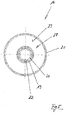
- the outer tube 19 has radial bulges 29 extending in the longitudinal direction 27 of the tube.
- Two radial bulges 29 are provided, as can be seen in particular from the illustration Fig. 7 results.
- Figures 9 to 11 refer to.
- a pipe socket 30 provided by the outer pipe 19 is provided, which provides the additional volume 23 serving as a collector volume. How a synopsis of Figures 9 to 11 results, the pipe socket is preferably aligned radially to the outer tube 19.
- FIGS 9 to 11 show the Figures 12 and 13 a further embodiment, according to which a plurality of pipe sockets 30 are provided. These pipe sockets 30 are arranged one behind the other in the longitudinal direction 27 of the pipe, equidistant distances preferably being given, as can be seen in particular from the illustration Fig. 13 results.
Landscapes
- Engineering & Computer Science (AREA)
- Textile Engineering (AREA)
- Washing And Drying Of Tableware (AREA)
- Heat-Exchange Devices With Radiators And Conduit Assemblies (AREA)
Applications Claiming Priority (1)
| Application Number | Priority Date | Filing Date | Title |
|---|---|---|---|
| DE102018115456.9A DE102018115456B4 (de) | 2018-06-27 | 2018-06-27 | Wasserführendes Haushaltsgerät |
Publications (2)
| Publication Number | Publication Date |
|---|---|
| EP3587659A1 true EP3587659A1 (fr) | 2020-01-01 |
| EP3587659B1 EP3587659B1 (fr) | 2020-12-16 |
Family
ID=66866959
Family Applications (1)
| Application Number | Title | Priority Date | Filing Date |
|---|---|---|---|
| EP19180143.0A Active EP3587659B1 (fr) | 2018-06-27 | 2019-06-14 | Appareil d'acheminement d'eau électroménager |
Country Status (3)
| Country | Link |
|---|---|
| EP (1) | EP3587659B1 (fr) |
| DE (1) | DE102018115456B4 (fr) |
| ES (1) | ES2840976T3 (fr) |
Citations (5)
| Publication number | Priority date | Publication date | Assignee | Title |
|---|---|---|---|---|
| DE2457182A1 (de) * | 1974-12-03 | 1976-06-10 | Stierlen Maquet Ag | Waermerueckgewinnungseinrichtung fuer geschirrspuelmaschinen |
| JPS6020056A (ja) * | 1983-07-15 | 1985-02-01 | Matsushita Electric Ind Co Ltd | 強制循環式太陽熱利用温水器 |
| EP0895036A2 (fr) * | 1997-07-10 | 1999-02-03 | Hecker, Monica | Système de génération de chaleur ou de réfrigération |
| EP2206824A2 (fr) | 2010-02-16 | 2010-07-14 | V-Zug AG | Appareil ménager doté d'une cuve, d'une pompe à chaleur et d'un réservoir |
| EP2682039A1 (fr) | 2012-07-03 | 2014-01-08 | Miele & Cie. KG | Lave-vaisselle doté d'une pompe à chaleur |
-
2018
- 2018-06-27 DE DE102018115456.9A patent/DE102018115456B4/de active Active
-
2019
- 2019-06-14 ES ES19180143T patent/ES2840976T3/es active Active
- 2019-06-14 EP EP19180143.0A patent/EP3587659B1/fr active Active
Patent Citations (5)
| Publication number | Priority date | Publication date | Assignee | Title |
|---|---|---|---|---|
| DE2457182A1 (de) * | 1974-12-03 | 1976-06-10 | Stierlen Maquet Ag | Waermerueckgewinnungseinrichtung fuer geschirrspuelmaschinen |
| JPS6020056A (ja) * | 1983-07-15 | 1985-02-01 | Matsushita Electric Ind Co Ltd | 強制循環式太陽熱利用温水器 |
| EP0895036A2 (fr) * | 1997-07-10 | 1999-02-03 | Hecker, Monica | Système de génération de chaleur ou de réfrigération |
| EP2206824A2 (fr) | 2010-02-16 | 2010-07-14 | V-Zug AG | Appareil ménager doté d'une cuve, d'une pompe à chaleur et d'un réservoir |
| EP2682039A1 (fr) | 2012-07-03 | 2014-01-08 | Miele & Cie. KG | Lave-vaisselle doté d'une pompe à chaleur |
Also Published As
| Publication number | Publication date |
|---|---|
| ES2840976T3 (es) | 2021-07-07 |
| DE102018115456A1 (de) | 2020-01-02 |
| DE102018115456B4 (de) | 2026-01-15 |
| EP3587659B1 (fr) | 2020-12-16 |
Similar Documents
| Publication | Publication Date | Title |
|---|---|---|
| EP2215954B1 (fr) | Lave-vaisselle doté d'une pompe à chaleur | |
| EP2682039B1 (fr) | Lave-vaisselle doté d'une pompe à chaleur | |
| EP3372139B1 (fr) | Machine à nettoyer, en particulier lave-vaisselle électroménager | |
| EP2443984B1 (fr) | Echangeur thermique coaxial pour un appareil ménager | |
| EP3114978B1 (fr) | Lave-vaisselle, notamment lave-vaisselle ménager | |
| DE102019121736A1 (de) | Geschirrspülmaschine und Verfahren zum Betrieb einer Geschirrspülmaschine | |
| EP2449945A2 (fr) | Appareil ménager doté d'une pompe à chaleur sur le circuit d'eau de traitement | |
| DE102014104373A1 (de) | Geschirrspülmaschine | |
| DE102019118807A1 (de) | Geschirrspülmaschine, insbesondere Haushaltsgeschirrspülmaschine | |
| WO2012028469A2 (fr) | Appareil de froid, en particulier appareil de froid électroménager | |
| DE102013114269B4 (de) | Geschirrspülmaschine | |
| EP3587659B1 (fr) | Appareil d'acheminement d'eau électroménager | |
| DE202004021113U1 (de) | Kältegerät mit Tauwasserverdampfer | |
| EP2682040B1 (fr) | Procédé de fonctionnement d'un lave-vaisselle | |
| DE102013114273B4 (de) | Geschirrspülmaschine | |
| DE102011107538A1 (de) | Kühl- und/oder Gefriergerät | |
| DE102017107051A1 (de) | Wärmepumpe | |
| EP3894761A1 (fr) | Machine frigorifique et appareil frigorifique utilisant celle-ci | |
| DE102023130575B4 (de) | Geschirrspülmaschine mit wärmepumpenvorrichtung und zwischenkreislauf | |
| DE102024206917B3 (de) | Haushalts-Geschirrspülmaschine | |
| DE3824385A1 (de) | Waermetauscher | |
| EP4141355A1 (fr) | Appareil de refroidissement et/ou de congélation | |
| DE102016212531A1 (de) | Wasserfilterbaugruppe und damit ausgestattetes Kältegerät | |
| DE102023212104A1 (de) | Kältegerät, Kältemittelkreislauf für ein Kältegerät, Wärmetauscher und Verfahren zum Herstellen eines Wärmetauschers | |
| DE10055915A1 (de) | Kältemittelkreislauf für eine Kältemaschine |
Legal Events
| Date | Code | Title | Description |
|---|---|---|---|
| PUAI | Public reference made under article 153(3) epc to a published international application that has entered the european phase |
Free format text: ORIGINAL CODE: 0009012 |
|
| STAA | Information on the status of an ep patent application or granted ep patent |
Free format text: STATUS: THE APPLICATION HAS BEEN PUBLISHED |
|
| AK | Designated contracting states |
Kind code of ref document: A1 Designated state(s): AL AT BE BG CH CY CZ DE DK EE ES FI FR GB GR HR HU IE IS IT LI LT LU LV MC MK MT NL NO PL PT RO RS SE SI SK SM TR |
|
| AX | Request for extension of the european patent |
Extension state: BA ME |
|
| STAA | Information on the status of an ep patent application or granted ep patent |
Free format text: STATUS: REQUEST FOR EXAMINATION WAS MADE |
|
| 17P | Request for examination filed |
Effective date: 20200701 |
|
| RBV | Designated contracting states (corrected) |
Designated state(s): AL AT BE BG CH CY CZ DE DK EE ES FI FR GB GR HR HU IE IS IT LI LT LU LV MC MK MT NL NO PL PT RO RS SE SI SK SM TR |
|
| GRAP | Despatch of communication of intention to grant a patent |
Free format text: ORIGINAL CODE: EPIDOSNIGR1 |
|
| STAA | Information on the status of an ep patent application or granted ep patent |
Free format text: STATUS: GRANT OF PATENT IS INTENDED |
|
| INTG | Intention to grant announced |
Effective date: 20200917 |
|
| GRAS | Grant fee paid |
Free format text: ORIGINAL CODE: EPIDOSNIGR3 |
|
| GRAA | (expected) grant |
Free format text: ORIGINAL CODE: 0009210 |
|
| STAA | Information on the status of an ep patent application or granted ep patent |
Free format text: STATUS: THE PATENT HAS BEEN GRANTED |
|
| AK | Designated contracting states |
Kind code of ref document: B1 Designated state(s): AL AT BE BG CH CY CZ DE DK EE ES FI FR GB GR HR HU IE IS IT LI LT LU LV MC MK MT NL NO PL PT RO RS SE SI SK SM TR |
|
| REG | Reference to a national code |
Ref country code: GB Ref legal event code: FG4D Free format text: NOT ENGLISH |
|
| REG | Reference to a national code |
Ref country code: DE Ref legal event code: R084 Ref document number: 502019000537 Country of ref document: DE |
|
| REG | Reference to a national code |
Ref country code: DE Ref legal event code: R096 Ref document number: 502019000537 Country of ref document: DE |
|
| REG | Reference to a national code |
Ref country code: IE Ref legal event code: FG4D Free format text: LANGUAGE OF EP DOCUMENT: GERMAN |
|
| REG | Reference to a national code |
Ref country code: GB Ref legal event code: 746 Effective date: 20201222 |
|
| REG | Reference to a national code |
Ref country code: AT Ref legal event code: REF Ref document number: 1345710 Country of ref document: AT Kind code of ref document: T Effective date: 20210115 |
|
| REG | Reference to a national code |
Ref country code: ES Ref legal event code: GC2A Effective date: 20210219 |
|
| PG25 | Lapsed in a contracting state [announced via postgrant information from national office to epo] |
Ref country code: FI Free format text: LAPSE BECAUSE OF FAILURE TO SUBMIT A TRANSLATION OF THE DESCRIPTION OR TO PAY THE FEE WITHIN THE PRESCRIBED TIME-LIMIT Effective date: 20201216 Ref country code: RS Free format text: LAPSE BECAUSE OF FAILURE TO SUBMIT A TRANSLATION OF THE DESCRIPTION OR TO PAY THE FEE WITHIN THE PRESCRIBED TIME-LIMIT Effective date: 20201216 Ref country code: GR Free format text: LAPSE BECAUSE OF FAILURE TO SUBMIT A TRANSLATION OF THE DESCRIPTION OR TO PAY THE FEE WITHIN THE PRESCRIBED TIME-LIMIT Effective date: 20210317 Ref country code: NO Free format text: LAPSE BECAUSE OF FAILURE TO SUBMIT A TRANSLATION OF THE DESCRIPTION OR TO PAY THE FEE WITHIN THE PRESCRIBED TIME-LIMIT Effective date: 20210316 |
|
| REG | Reference to a national code |
Ref country code: NL Ref legal event code: MP Effective date: 20201216 |
|
| PG25 | Lapsed in a contracting state [announced via postgrant information from national office to epo] |
Ref country code: BG Free format text: LAPSE BECAUSE OF FAILURE TO SUBMIT A TRANSLATION OF THE DESCRIPTION OR TO PAY THE FEE WITHIN THE PRESCRIBED TIME-LIMIT Effective date: 20210316 Ref country code: SE Free format text: LAPSE BECAUSE OF FAILURE TO SUBMIT A TRANSLATION OF THE DESCRIPTION OR TO PAY THE FEE WITHIN THE PRESCRIBED TIME-LIMIT Effective date: 20201216 Ref country code: LV Free format text: LAPSE BECAUSE OF FAILURE TO SUBMIT A TRANSLATION OF THE DESCRIPTION OR TO PAY THE FEE WITHIN THE PRESCRIBED TIME-LIMIT Effective date: 20201216 |
|
| PG25 | Lapsed in a contracting state [announced via postgrant information from national office to epo] |
Ref country code: HR Free format text: LAPSE BECAUSE OF FAILURE TO SUBMIT A TRANSLATION OF THE DESCRIPTION OR TO PAY THE FEE WITHIN THE PRESCRIBED TIME-LIMIT Effective date: 20201216 Ref country code: NL Free format text: LAPSE BECAUSE OF FAILURE TO SUBMIT A TRANSLATION OF THE DESCRIPTION OR TO PAY THE FEE WITHIN THE PRESCRIBED TIME-LIMIT Effective date: 20201216 |
|
| REG | Reference to a national code |
Ref country code: ES Ref legal event code: FG2A Ref document number: 2840976 Country of ref document: ES Kind code of ref document: T3 Effective date: 20210707 |
|
| REG | Reference to a national code |
Ref country code: LT Ref legal event code: MG9D |
|
| PG25 | Lapsed in a contracting state [announced via postgrant information from national office to epo] |
Ref country code: LT Free format text: LAPSE BECAUSE OF FAILURE TO SUBMIT A TRANSLATION OF THE DESCRIPTION OR TO PAY THE FEE WITHIN THE PRESCRIBED TIME-LIMIT Effective date: 20201216 Ref country code: PT Free format text: LAPSE BECAUSE OF FAILURE TO SUBMIT A TRANSLATION OF THE DESCRIPTION OR TO PAY THE FEE WITHIN THE PRESCRIBED TIME-LIMIT Effective date: 20210416 Ref country code: RO Free format text: LAPSE BECAUSE OF FAILURE TO SUBMIT A TRANSLATION OF THE DESCRIPTION OR TO PAY THE FEE WITHIN THE PRESCRIBED TIME-LIMIT Effective date: 20201216 Ref country code: CZ Free format text: LAPSE BECAUSE OF FAILURE TO SUBMIT A TRANSLATION OF THE DESCRIPTION OR TO PAY THE FEE WITHIN THE PRESCRIBED TIME-LIMIT Effective date: 20201216 Ref country code: EE Free format text: LAPSE BECAUSE OF FAILURE TO SUBMIT A TRANSLATION OF THE DESCRIPTION OR TO PAY THE FEE WITHIN THE PRESCRIBED TIME-LIMIT Effective date: 20201216 Ref country code: SM Free format text: LAPSE BECAUSE OF FAILURE TO SUBMIT A TRANSLATION OF THE DESCRIPTION OR TO PAY THE FEE WITHIN THE PRESCRIBED TIME-LIMIT Effective date: 20201216 Ref country code: SK Free format text: LAPSE BECAUSE OF FAILURE TO SUBMIT A TRANSLATION OF THE DESCRIPTION OR TO PAY THE FEE WITHIN THE PRESCRIBED TIME-LIMIT Effective date: 20201216 |
|
| PG25 | Lapsed in a contracting state [announced via postgrant information from national office to epo] |
Ref country code: PL Free format text: LAPSE BECAUSE OF FAILURE TO SUBMIT A TRANSLATION OF THE DESCRIPTION OR TO PAY THE FEE WITHIN THE PRESCRIBED TIME-LIMIT Effective date: 20201216 |
|
| REG | Reference to a national code |
Ref country code: DE Ref legal event code: R097 Ref document number: 502019000537 Country of ref document: DE |
|
| PG25 | Lapsed in a contracting state [announced via postgrant information from national office to epo] |
Ref country code: IS Free format text: LAPSE BECAUSE OF FAILURE TO SUBMIT A TRANSLATION OF THE DESCRIPTION OR TO PAY THE FEE WITHIN THE PRESCRIBED TIME-LIMIT Effective date: 20210416 |
|
| PLBE | No opposition filed within time limit |
Free format text: ORIGINAL CODE: 0009261 |
|
| STAA | Information on the status of an ep patent application or granted ep patent |
Free format text: STATUS: NO OPPOSITION FILED WITHIN TIME LIMIT |
|
| PG25 | Lapsed in a contracting state [announced via postgrant information from national office to epo] |
Ref country code: AL Free format text: LAPSE BECAUSE OF FAILURE TO SUBMIT A TRANSLATION OF THE DESCRIPTION OR TO PAY THE FEE WITHIN THE PRESCRIBED TIME-LIMIT Effective date: 20201216 |
|
| 26N | No opposition filed |
Effective date: 20210917 |
|
| PG25 | Lapsed in a contracting state [announced via postgrant information from national office to epo] |
Ref country code: DK Free format text: LAPSE BECAUSE OF FAILURE TO SUBMIT A TRANSLATION OF THE DESCRIPTION OR TO PAY THE FEE WITHIN THE PRESCRIBED TIME-LIMIT Effective date: 20201216 |
|
| PG25 | Lapsed in a contracting state [announced via postgrant information from national office to epo] |
Ref country code: MC Free format text: LAPSE BECAUSE OF FAILURE TO SUBMIT A TRANSLATION OF THE DESCRIPTION OR TO PAY THE FEE WITHIN THE PRESCRIBED TIME-LIMIT Effective date: 20201216 |
|
| PG25 | Lapsed in a contracting state [announced via postgrant information from national office to epo] |
Ref country code: SI Free format text: LAPSE BECAUSE OF FAILURE TO SUBMIT A TRANSLATION OF THE DESCRIPTION OR TO PAY THE FEE WITHIN THE PRESCRIBED TIME-LIMIT Effective date: 20201216 |
|
| REG | Reference to a national code |
Ref country code: BE Ref legal event code: MM Effective date: 20210630 |
|
| PG25 | Lapsed in a contracting state [announced via postgrant information from national office to epo] |
Ref country code: LU Free format text: LAPSE BECAUSE OF NON-PAYMENT OF DUE FEES Effective date: 20210614 |
|
| PG25 | Lapsed in a contracting state [announced via postgrant information from national office to epo] |
Ref country code: IE Free format text: LAPSE BECAUSE OF NON-PAYMENT OF DUE FEES Effective date: 20210614 |
|
| PG25 | Lapsed in a contracting state [announced via postgrant information from national office to epo] |
Ref country code: IS Free format text: LAPSE BECAUSE OF FAILURE TO SUBMIT A TRANSLATION OF THE DESCRIPTION OR TO PAY THE FEE WITHIN THE PRESCRIBED TIME-LIMIT Effective date: 20210416 |
|
| PG25 | Lapsed in a contracting state [announced via postgrant information from national office to epo] |
Ref country code: BE Free format text: LAPSE BECAUSE OF NON-PAYMENT OF DUE FEES Effective date: 20210630 |
|
| REG | Reference to a national code |
Ref country code: CH Ref legal event code: PL |
|
| PG25 | Lapsed in a contracting state [announced via postgrant information from national office to epo] |
Ref country code: LI Free format text: LAPSE BECAUSE OF NON-PAYMENT OF DUE FEES Effective date: 20220630 Ref country code: CH Free format text: LAPSE BECAUSE OF NON-PAYMENT OF DUE FEES Effective date: 20220630 |
|
| PG25 | Lapsed in a contracting state [announced via postgrant information from national office to epo] |
Ref country code: CY Free format text: LAPSE BECAUSE OF FAILURE TO SUBMIT A TRANSLATION OF THE DESCRIPTION OR TO PAY THE FEE WITHIN THE PRESCRIBED TIME-LIMIT Effective date: 20201216 |
|
| P01 | Opt-out of the competence of the unified patent court (upc) registered |
Effective date: 20230528 |
|
| PG25 | Lapsed in a contracting state [announced via postgrant information from national office to epo] |
Ref country code: HU Free format text: LAPSE BECAUSE OF FAILURE TO SUBMIT A TRANSLATION OF THE DESCRIPTION OR TO PAY THE FEE WITHIN THE PRESCRIBED TIME-LIMIT; INVALID AB INITIO Effective date: 20190614 |
|
| PG25 | Lapsed in a contracting state [announced via postgrant information from national office to epo] |
Ref country code: MK Free format text: LAPSE BECAUSE OF FAILURE TO SUBMIT A TRANSLATION OF THE DESCRIPTION OR TO PAY THE FEE WITHIN THE PRESCRIBED TIME-LIMIT Effective date: 20201216 |
|
| PG25 | Lapsed in a contracting state [announced via postgrant information from national office to epo] |
Ref country code: MT Free format text: LAPSE BECAUSE OF FAILURE TO SUBMIT A TRANSLATION OF THE DESCRIPTION OR TO PAY THE FEE WITHIN THE PRESCRIBED TIME-LIMIT Effective date: 20201216 |
|
| PGFP | Annual fee paid to national office [announced via postgrant information from national office to epo] |
Ref country code: DE Payment date: 20250630 Year of fee payment: 7 |
|
| PGFP | Annual fee paid to national office [announced via postgrant information from national office to epo] |
Ref country code: GB Payment date: 20250617 Year of fee payment: 7 |
|
| PGFP | Annual fee paid to national office [announced via postgrant information from national office to epo] |
Ref country code: FR Payment date: 20250624 Year of fee payment: 7 |
|
| PGFP | Annual fee paid to national office [announced via postgrant information from national office to epo] |
Ref country code: TR Payment date: 20250603 Year of fee payment: 7 |
|
| REG | Reference to a national code |
Ref country code: AT Ref legal event code: MM01 Ref document number: 1345710 Country of ref document: AT Kind code of ref document: T Effective date: 20240614 |
|
| PGFP | Annual fee paid to national office [announced via postgrant information from national office to epo] |
Ref country code: ES Payment date: 20250710 Year of fee payment: 7 |
|
| PGFP | Annual fee paid to national office [announced via postgrant information from national office to epo] |
Ref country code: IT Payment date: 20250623 Year of fee payment: 7 |
|
| PG25 | Lapsed in a contracting state [announced via postgrant information from national office to epo] |
Ref country code: AT Free format text: LAPSE BECAUSE OF NON-PAYMENT OF DUE FEES Effective date: 20240614 |
|
| PGFP | Annual fee paid to national office [announced via postgrant information from national office to epo] |
Ref country code: AT Payment date: 20260410 Year of fee payment: 5 |