EP3587683B1 - Dispositif de bouton-poussoir pour soupape de vidange - Google Patents
Dispositif de bouton-poussoir pour soupape de vidange Download PDFInfo
- Publication number
- EP3587683B1 EP3587683B1 EP19183191.6A EP19183191A EP3587683B1 EP 3587683 B1 EP3587683 B1 EP 3587683B1 EP 19183191 A EP19183191 A EP 19183191A EP 3587683 B1 EP3587683 B1 EP 3587683B1
- Authority
- EP
- European Patent Office
- Prior art keywords
- push button
- seat
- drain valve
- bracket
- flush
- Prior art date
- Legal status (The legal status is an assumption and is not a legal conclusion. Google has not performed a legal analysis and makes no representation as to the accuracy of the status listed.)
- Active
Links
Images


Classifications
-
- E—FIXED CONSTRUCTIONS
- E03—WATER SUPPLY; SEWERAGE
- E03D—WATER-CLOSETS OR URINALS WITH FLUSHING DEVICES; FLUSHING VALVES THEREFOR
- E03D1/00—Water flushing devices with cisterns ; Setting up a range of flushing devices or water-closets; Combinations of several flushing devices
- E03D1/30—Valves for high or low level cisterns; Their arrangement ; Flushing mechanisms in the cistern, optionally with provisions for a pre-or a post- flushing and for cutting off the flushing mechanism in case of leakage
- E03D1/34—Flushing valves for outlets; Arrangement of outlet valves
-
- E—FIXED CONSTRUCTIONS
- E03—WATER SUPPLY; SEWERAGE
- E03D—WATER-CLOSETS OR URINALS WITH FLUSHING DEVICES; FLUSHING VALVES THEREFOR
- E03D5/00—Special constructions of flushing devices, e.g. closed flushing system
- E03D5/02—Special constructions of flushing devices, e.g. closed flushing system operated mechanically or hydraulically (or pneumatically) also details such as push buttons, levers and pull-card therefor
- E03D5/09—Special constructions of flushing devices, e.g. closed flushing system operated mechanically or hydraulically (or pneumatically) also details such as push buttons, levers and pull-card therefor directly by the hand
Definitions
- the application relates to a drain valve button bracket with a directed key, named push button hereinafter.
- a button bracket of the existing drain valve has a structure capable of locking a water tank cover, which is in threaded connection with the drain valve through a button main body to clamp and fix the water tank cover.
- a push button capable of axially sliding is arranged in the button main body, the directions of the existing push button and the button main body are fixed on the circumferential direction. Therefore, when the button main body is rotated, the push button also rotates with the button main body. After being locked, the position of the push button is not fixed. On one hand, the degree of freedom of design of the push button is small and is not suitable for the situation in which the push button needs to be directed.
- US2001/0042265A1 discloses a flush valve, adapted to be mounted in the tank of a toilet and including a selector assembly and a flush valve.
- the selector assembly is accessible from outside the toilet and provides for initiation of the flushing operation and an alternative choice between a larger flush water volume and a smaller flush water volume.
- a support structure provides for both axial and radial movement of the selector assembly relative to the flush valve in order to facilitate mounting and aligning of the flush valve assembly.
- a slide mechanism provides for variation of at least the smaller flush water volume.
- CN201106202Y discloses a drain valve which comprises a valve seat.
- a water opening is arranged at the lower end of the valve seat.
- a valve spool which can slide up and down corresponding to the valve seat is installed in the valve seat.
- a control device which controls the valve spool to be up and down is connected on the valve spool.
- a water-seal component is installed at the lower end of the valve spool.
- CN107044158 discloses a stool flushing controller and a control method thereof;
- the stool flushing controller comprises a hollow housing with a top opening;
- the housing lower portion is provided with an ejection execution assembly capable of sliding up and down on the housing;
- the housing upper portion is provided with a push assembly capable of sliding up and down on the housing;
- a motor driving member is arranged between the push assembly and the ejection execution assembly;
- the housing upper portion is detachably provided with a mount ring A used for mounting and limiting the push assembly;
- the push assembly is provided with an infrared control assembly;
- the infrared control assembly controls the motor driving member to rotate through infrared induction, thus driving the ejection execution assembly to telescope with respect to the housing.
- CN2744747Y discloses a height-adjustable two-press type drainage valve button set.
- a supporter is arranged on the drainage valve; a slide block is inserted in the chute of the support; a container is fixed on the center hole of the slide block; two adapting pieces and a back-moving spring are arranged on the container.
- the lower parts of the two adapting pieces are connected with the upper end of a connecting bar, whose lower end matches the controlling switch; the upper parts of the two adapting pieces are arranged to overlap each other and form a central screw hole.
- the application provides a drain valve button bracket with a directed push button, a push button component can be move relative to a push button main body on the axial direction and the circumferential direction, when the push button main body is rotated to lock a water tank cover, the push button component does not rotate with the rotation of the push button main body, so that the direction of the push button is fixed, the position of the push button is unified, the application range is wide, and the structure is simple.
- a drain valve button bracket with a directed push button including:
- the push button component includes a push button and a push button seat, which are assembled together, the push button and the push button seat are slidably arranged in the accommodating cavity, the connecting sleeve is rotatably connected with the push button seat, the compression bar is in circumferential limiting fit with the push button seat, and when the push button is pressed and operated, the push button drives the compression bar to move along the axial direction through the push button seat and the connecting sleeve to drive the drain valve to open to drain water.
- the push button seat is provided with an annular groove
- one end of the connecting sleeve is provided with a buckle
- the buckle is buckled in the annular groove in a circumferential movable manner
- the connecting sleeve is rotatably connected with the push button seat via the cooperation of the buckle and the annular groove.
- the compression bar penetrates through the connecting sleeve to cooperate with the push button seat, and the compression bar forms a threaded connection with the connecting sleeve and is in circumferential limiting fit with the push button seat.
- the push button seat is provided with a non-circular hole
- the compression bar is provided with a non-circular cooperation portion corresponding to the non-circular hole of the push button seat, and the compression bar is in circumferential limiting fit with the push button seat through the non-circular hole and the non-circular cooperation portion; and furthermore, the compression bar and/or the push button seat are provided with a guiding inclined plane for facilitating the insertion of the compression bar into the non-circular hole.
- a threaded pipe in threaded connection with the bracket is arranged at the bottom of the push button main body, and a lower part of the connecting sleeve is sleeved in the threaded pipe and forms circumferential limiting with the threaded pipe.
- the bracket is provided with a nut, the nut is in threaded connection with the push button main body, the compression bar is arranged on the nut in the circumferential limiting manner, and the pitches of the threads on the nut, the push button main body, the compression bar and the connecting sleeve are equal.
- a sliding slot is formed in the top of the bracket, a sliding plate is slidably installed in the sliding slot along a first direction, the nut is slidably installed on the sliding plate along a second direction, and the first direction is perpendicular to the second direction.
- the bracket includes two connecting arms, the two connecting arms are installed on both sides of the drain valve in a height adjustable manner, a pressing plate is arranged at the bottom of the compression bar, the pressing plate cooperates with a lifting rod that is rotatably arranged on the drain valve, and when the pressing plate presses one end of the lifting rod, the other end of the lifting rod tilts and lifts a sealing component of the drain valve to open the drain valve.
- the push button includes a full-row or full-drainage or full-flush push button and a semi-row or semi-drainage or semi-flush push button
- the full-flush push button is fixedly installed on the push button seat
- the semi-flush push button is movably installed on the push button seat
- a stroke of the full-flush push button to drive the push button seat to move when being driven is greater than the stroke of the semi-flush push button to drive the push button seat to move when being driven
- the drain valve button bracket further includes further includes further includes a first elastic member for resetting the push button component.
- the push button includes a full-flush push button and a semi-flush push button
- the push button seat includes a full-flush buckle seat fixedly connected with the full-flush push button, a semi-flush buckle seat fixedly connected with the semi-flush push button, and a rotation stop seat rotatably connected with the connecting sleeve
- the compression bar is in circumferential limiting fit with the rotation stop seat
- the full-flush buckle seat and the semi-flush buckle seat are both in axial sliding fit and circumferential limiting fit with the rotation stop seat.
- the drain valve button bracket further includes a carrying tray, the carrying tray is rotatably arranged in the accommodating cavity of the push button main body relative to the push button main body, the full-flush buckle seat and the semi-flush buckle seat are slidably installed on the carrying tray, the drain valve button bracket further includes a second elastic member, a third elastic member and a fourth elastic member for respectively resetting the full-flush buckle seat, the semi-flush buckle seat and the rotation stop seat.
- the direction of the push button is fixed, the position of the push button is unified, the application range is wide, and the structure is simple.
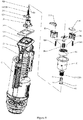
- a drain valve button bracket with a directed push button in the present embodiment includes a bracket 11, a push button main body 20, a push button component, a connecting sleeve 40 and a compression bar 50.
- the bracket is arranged on a drain valve 10 in a circumferential limiting manner, that is, the bracket 11 does not rotate on the drain valve 10 on the circumferential direction.
- the push button main body 20 has an accommodating cavity 21 and is in threaded connection with the bracket 11; the push button component is slidably arranged in the accommodating cavity 21 and is capable of rotating relative to the push button main body 20.
- the connecting sleeve 40 is arranged in the push button main body 20 in an axially movable manner, rotates along with the push button main body 20 and is rotatably connected with the push button component.
- the compression bar 50 is arranged on the bracket 11 in the circumferential limiting manner, is in circumferential limiting fit with the push button component and is in threaded connection with the connecting sleeve 40; and when the push button component is operated, the connecting sleeve 40 drives the compression bar 50 to move along the axial direction to drive the drain valve 10 to drain water.
- the push button component includes a push button 31 and a push button seat 32, which are assembled together, the push button 31 and the push button seat 32 are slidably arranged in the accommodating cavity 21, the connecting sleeve 40 is rotatably connected with the push button seat 32, the compression bar 50 is in circumferential limiting fit with the push button seat 32, and when the push button 31 is pressed, the push button 31 drives the compression bar 50 to move along the axial direction through the push button seat 32 and the connecting sleeve 40 to drive the drain valve 10 to drain water.
- an annular groove 321 is formed in an outer wall of the push button seat 32, one end of the connecting sleeve 40 is provided with a buckle 41, the buckle 41 is buckled in the annular groove 321 in a circumferential movable manner, and the connecting sleeve 40 is rotatably connected with the push button seat 32 via the cooperation of the buckle 41 and the annular groove 321.
- the compression bar 50 is in circumferential limiting fit with the push button seat 32, in the present embodiment, the compression bar 50 penetrates through the connecting sleeve 40 to cooperate with the push button seat 32, and the compression bar 50 is in circumferential limiting fit with the push button seat 32 before forming the threaded connection with the connecting sleeve 40. Therefore, the push button 31 is directed easily, the effect of the directed push button is better, and the construct is simpler.
- the connecting sleeve 40 is provided with a limiting groove 44
- the push button main body 20 is provided with a limiting rib 23
- the limiting groove 44 and the limiting rib 23 are in limiting fit with each other, so that the connecting sleeve 40 and the push button main body 20 synchronously rotate.
- the push button seat 32 is provided with a non-circular hole 322
- the compression bar 50 is provided with a non-circular cooperation portion 52 corresponding to the non-circular hole 322 of the push button seat 32, and the compression bar 50 is in circumferential limiting fit with the push button seat 32 through the non-circular hole 322 and the non-circular cooperation portion 52.
- the non-circular hole 322 is a straight hole
- the non-circular cooperation portion 52 is a straight clamping strip, so that the structure is simple, the assembly is convenient, the circumferential limiting of the compression bar 50 on the push button seat 32 can also be achieved by using other non-circular structure, and is not limited thereto.
- the compression bar 50 is provided with a guiding inclined plane 53 for facilitating the insertion of the compression bar 50 into the non-circular hole 322, and a guiding inclined plane 323 for facilitating the insertion of the compression bar 50 into the non-circular hole 322 is also arranged on the inner wall of the non-circular hole 322 of the push button seat 32, the guiding inclined plane 53 on the compression bar 50 and the guiding inclined plane 323 on the push button seat 32 cooperate with each other for guiding.
- a threaded pipe 22 is arranged at the bottom of the push button main body 20, and the connecting sleeve 40 is sleeved in the threaded pipe 22 and forms circumferential limiting with the threaded pipe 22.
- the bracket 11 is provided with a nut 12, the nut 12 is in threaded connection with the push button main body 20, the compression bar 50 is arranged on the nut 12 in the circumferential limiting manner, and the pitches of the threads on the nut 12, the push button main body 20, the compression bar 50 and the connecting sleeve 40 are equal, so that the threaded connection between the push button main body 20 and the nut 12 generates no mutual interference with the threaded connection between the compression bar 50 and the connecting sleeve 40.
- the threaded pipe 22 is provided with a first external thread 221
- the nut 12 is provided with a first internal thread 121
- the compression bar 50 is provided with a second external thread 51
- the connecting sleeve 40 is provided with a second internal thread 42
- the pitches of the first external thread 221, the first internal thread 121, the second external thread 51 and the second internal thread 42 are all equal.
- a sliding slot 13 is formed in the top of the bracket 11, a sliding plate 14 is slidably installed in the sliding slot 13 along a first direction, the nut 12 is slidably installed on the sliding plate 14 along a second direction, and the first direction is perpendicular to the second direction.
- the bracket 11 includes two connecting arms 15, the two connecting arms 15 are installed on both sides of the drain valve 10 in a height adjustable manner.
- a pressing plate 54 is arranged at the bottom of the compression bar 50, the pressing plate 54 cooperates with a lifting rod 16 that is rotatably arranged on the drain valve 10.
- the pressing plate 54 presses one end of the lifting rod 16, the other end of the lifting rod 16 tilts and lifts a sealing component of the drain valve 10 to open the drain valve.
- the push button 31 includes a full-flush push button 311 and a semi-flush push button 312, the full-flush push button 311 is fixedly installed on the push button seat 32, the semi-flush push button 312 is movably installed on the push button seat 32.
- a stroke of the full-flush push button 311 for driving the push button seat 32 to move when being driven is greater than the stroke of the semi-flush push button 312 for driving the push button seat 32 to move when being driven
- the drain valve button bracket further includes a first elastic member 33 for resetting the push button component, and the first elastic member 33 comprises pressure spring.
- the full-flush push button 311 and the semi-flush push button 312 are both installed on the push button seat 32.
- the movement stroke of the push button seat 32 is longer, and the push button seat 32 drives the compression bar 50 to move along the axial direction via the connecting sleeve 40 to drive a sealing component of the drain valve 10 to move upward for a relatively longer stroke to achieve full drainage; and when the semi-flush push button 312 is pressed, the movement stroke of the push button seat 32 is shorter, the push button seat 32 drives the compression bar 50 to move along the axial direction via the connecting sleeve 40 to drive the sealing component of the drain valve 10 to move upward for a relatively shorter stroke to achieve semi-drainage.
- the push button main body 20 is placed on a mounting hole of a water tank cover of a toilet (not shown in the figures), the connecting arms 15 can slide up and down to adjust the height of the bracket 11, the threaded pipe of the push button main body 20 is aligned and contact with the nut 12.
- the straight clamping strip 52 of the compression bar 50 automatically aligns and is inserted into the straight hole 322 of the push button seat 32, the push button main body 20 is threadedly connected with the nut 12 by rotating the push button main body 20, while the push button main body 20 is in threaded connection with the nut 12, the connecting sleeve 40 is also in threaded connection with the compression bar 50, until the push button main body 20 and the nut 12 lock the water tank cover, and accordingly the assembly of the button bracket is completed.
- the threaded connection between the connecting sleeve 40 and the compression bar 50 does not needs to be performed with the threaded connection between the push button main body 20 and the nut 12, and the threaded connection between the connecting sleeve 40 and the compression bar 50 would be performed before or after the threaded connection between the push button main body 20 and the nut 12.
- the push button 31 includes a full-flush push button 311 and a semi-flush push button 312
- the push button seat 32 includes a full-flush buckle seat 34 fixedly connected with the full-flush push button 311, a semi-flush buckle seat 35 fixedly connected with the semi-flush push button 312, and a rotation stop seat 36 rotatably connected with the connecting sleeve 40
- the compression bar 50 is in circumferential limiting fit with the rotation stop seat 36
- the full-flush buckle seat 34 and the semi-flush buckle seat 35 are both in axial sliding fit and circumferential limiting fit with the rotation stop seat 36.
- the full-flush push button 311 is fixed to the push button seat 32, when the semi-flush push button 312 is pressed, the full-flush push button 311 is driven to move together.
- the full-flush push button 311 and the semi-flush push button 312 would move independent of each other in the second embodiment, the rotation stop seat 36 could be driven to rotate by pressing the full-flush push button 311 or the semi-flush push button 312, then the rotation stop seat 36 drives the connecting sleeve 40 to move, and the connecting sleeve 40 drives the compression bar 50 to move so as to activate the drain valve.
- the semi-flush push button 312 is not driven when the full-flush push button 311 is pressed, or, the full-flush push button 311 is not driven when the semi-flush push button 312 is pressed, full-drainage and semi-drainage can be distinguished more easily, and the operation is more visual.
- the present embodiment further includes a carrying tray 60, the carrying tray 60 is rotatably arranged in the accommodating cavity 21 of the push button main body 20 relative to the push button main body 20, the full-flush buckle seat 34 and the semi-flush buckle seat 35 are slidably installed on the carrying tray 60, the drain valve button bracket further includes a second elastic member 341, a third elastic member 351 and a fourth elastic member 361 for respectively resetting the full-flush buckle seat 34, the semi-flush buckle seat 35 and the rotation stop seat 36, and the second elastic member 341, the third elastic member 351 and the fourth elastic member 361 comprise pressure springs.
- the push button main body 20 is separately connected with the threaded pipe 22, and the threaded pipe 22 is connected to the bottom of the push button main body 20.
- the annular groove 321 of the push button seat 32 is formed in the rotation stop seat 36, and the buckle 41 of the connecting sleeve 40 cooperates with the annular groove 321 in the rotation stop seat 36.
- the limiting groove 44 is formed in the connecting sleeve 40, the limiting rib 23 is arranged on the inner wall of the threaded pipe 22, and the limiting groove 44 and the limiting rib 23 are in limiting fit with each other, so that the connecting sleeve 40 and the threaded pipe 22 synchronously rotate.
- the application also provides a toilet, which comprises a drain valve and the drain valve button bracket, and the bracket is arranged on the drain valve in a circumferential limiting manner.
Landscapes
- Engineering & Computer Science (AREA)
- Health & Medical Sciences (AREA)
- Life Sciences & Earth Sciences (AREA)
- Hydrology & Water Resources (AREA)
- Public Health (AREA)
- Water Supply & Treatment (AREA)
- Mechanical Engineering (AREA)
- Aviation & Aerospace Engineering (AREA)
- Mechanically-Actuated Valves (AREA)
- Preventing Unauthorised Actuation Of Valves (AREA)
- Sink And Installation For Waste Water (AREA)
Claims (13)
- Support de bouton de soupape de vidange avec un bouton-poussoir dirigé, comprenant :un support (11), destiné à être disposé sur une soupape de vidange (10) de manière limitative circonférencielle, c'est-à-dire de manière rotationnelle limitative dans la direction circonférencielle ;un corps principal de bouton-poussoir (20), ayant une cavité de réception (21) et en raccord fileté avec le support ;un composant de bouton-poussoir, disposé de manière coulissante dans la cavité de réception (21) et pouvant tourner par rapport au corps principal de bouton-poussoir (20) ;une barre de compression (50), disposée sur le support de manière limitative circonférencielle, en ajustement limitatif circonférentiel avec le composant de bouton-poussoir ;caractérisé en ce qu'il comprend en outre un manchon de raccordement (40), dont une partie supérieure est disposée dans le corps principal de bouton-poussoir (20) de manière à pouvoir se déplacer axialement, en mesure de tourner avec le corps principal de bouton-poussoir (20) et relié de manière rotative au composant de bouton-poussoir ;et en ce que la barre de compression (50), est en raccord fileté avec le manchon de raccordement (40) ; eten ce que le manchon de raccordement (40) est configuré pour entraîner la barre de compression (50) à se déplacer le long de la direction axiale de manière à pouvoir entraîner la soupape de vidange (10) pour qu'elle s'ouvre pour évacuer l'eau, lorsque l'on actionne le bouton-poussoir.
- Support de bouton de soupape de vidange avec le bouton-poussoir dirigé selon la revendication 1, où le composant de bouton-poussoir comprend un bouton-poussoir (31) et un siège de bouton-poussoir (32), qui sont assemblés ensemble, et le bouton-poussoir (31) et le siège de bouton-poussoir (32) sont disposés de manière coulissante dans la cavité de réception (21), le manchon de raccordement (40) est relié de manière rotative au siège de bouton-poussoir (32), la barre de compression (50) est en ajustement limitatif circonférentiel avec le siège de bouton-poussoir (32), et lorsque le bouton-poussoir (31) est pressé et actionné, le bouton-poussoir (31) entraîne la barre de compression (50) pour qu'elle se déplace le long de sa direction axiale par le siège de bouton-poussoir (32) et le manchon de raccordement (40) de manière à entraîner la soupape de vidange (10) pour évacuer l'eau.
- Support de bouton de soupape de vidange avec le bouton-poussoir dirigé selon la revendication 2, où le siège de bouton-poussoir (32) est muni d'une rainure annulaire (321), une extrémité du manchon de raccordement (40) est munie d'une boucle (41), la boucle (41) est bouclée dans la rainure annulaire (321) de manière mobile circonférencielle, et le manchon de raccordement (40) est relié de manière rotative au siège de bouton-poussoir (32) par la coopération de la boucle (41) et de la rainure annulaire (321).
- Support de bouton de soupape de vidange avec le bouton-poussoir dirigé selon la revendication 2 ou 3, où la barre de compression (50) pénètre à travers le manchon de raccordement (40) pour coopérer avec le siège de bouton-poussoir (32), et la barre de compression (50) forme un raccord fileté avec le manchon de raccordement (40) et est en ajustement limitatif circonférentiel avec le siège de bouton-poussoir (32).
- Support de bouton de soupape de vidange avec le bouton-poussoir dirigé selon la revendication 2 ou 3, où le siège de bouton-poussoir (32) est pourvu d'un trou non circulaire (322), la barre de compression (50) est pourvue d'une partie de coopération non circulaire (52) correspondant au trou non circulaire (322) du siège de bouton-poussoir (32), et la barre de compression (50) est en ajustement limitatif circonférentiel avec le siège de bouton-poussoir (32) à travers le trou non circulaire (322) et la partie de coopération non circulaire (52) ; et au moins l'un entre la barre de compression (50) et le siège de bouton-poussoir (32) est pourvu d'un plan incliné de guidage (53) pour faciliter l'insertion de la barre de compression (50) dans le trou non circulaire (322).
- Support de bouton de soupape de vidange avec le bouton-poussoir dirigé selon la revendication 1, où un tube fileté (22) en raccord fileté avec le support est disposé au fond du corps principal du bouton-poussoir (20), et une partie inférieure du manchon de raccordement (40) est emmanchée dans le tube fileté (22) et forme une limitation circonférentielle avec le tube fileté (22).
- Support de bouton de soupape de vidange avec le bouton-poussoir dirigé selon la revendication 1, où le support (11) est muni d'un écrou (12), l'écrou (12) est en raccord fileté avec le corps principal de bouton-poussoir (20), la barre de compression (50) est disposée sur l'écrou (12) de manière limitative circonférencielle, et les pas des filetages sur l'écrou (12), le corps principal de bouton-poussoir (20), la barre de compression (50) et le manchon de raccordement (40) sont identiques.
- Support de bouton de soupape de vidange avec le bouton-poussoir dirigé selon la revendication 7, où une fente coulissante (13) est formée dans le haut du support (11), une plaque coulissante (14) est installée de manière coulissante dans la fente coulissante (13) le long d'une première direction, l'écrou (12) est installé de manière coulissante sur la plaque coulissante (14) le long d'une seconde direction, et la première direction est perpendiculaire à la seconde direction.
- Support de bouton de soupape de vidange avec le bouton-poussoir dirigé selon la revendication 2 ou 3, où le bouton-poussoir (31) comprend un bouton-poussoir pour vidange complète (311) et un bouton-poussoir pour demi vidange (312), le bouton-poussoir pour vidange complète (311) est installé de manière fixe sur le siège de bouton-poussoir (32), le bouton-poussoir pour demi vidange (312) est installé de manière mobile sur le siège de bouton-poussoir (32), une course du bouton-poussoir pour vidange complète (311) pour entraîner le siège de bouton-poussoir (32) à se déplacer lorsqu'il est entraîné est supérieure à la course du bouton-poussoir pour demi vidange (312) pour entraîner le siège de bouton-poussoir (32) à se déplacer lorsqu'il est actionné, et le support de bouton de la soupape de vidange comprend en outre un premier élément élastique (33) pour réinitialiser le composant de bouton-poussoir.
- Support de bouton de soupape de vidange avec le bouton-poussoir dirigé selon la revendication 2 ou 3, où le bouton-poussoir (31) comprend un bouton-poussoir pour vidange complète (311) et un bouton-poussoir pour demi vidange (312), le siège de bouton-poussoir (32) comprend un siège de boucle pour vidange complète (34) relié de manière fixe au bouton-poussoir pour vidange complète (311), un siège de boucle pour demi vidange (35) relié de manière fixe au bouton-poussoir pour demi vidange (312), et un siège d'arrêt de rotation (36) relié de manière rotative au manchon de raccordement (40), la barre de compression (50) est en ajustement limitatif circonférentiel avec le siège d'arrêt de rotation (36), et le siège de boucle pour vidange complète (34) et le siège de boucle pour demi vidange (35) sont tous deux en ajustement coulissant axial et en ajustement limitatif circonférentiel avec le siège d'arrêt de rotation (36) .
- Support de bouton de soupape de vidange avec le bouton-poussoir dirigé selon la revendication 10, comprenant en outre un plateau de support (60), où le plateau de support (60) est disposé dans la cavité de réception (21) du corps principal de bouton-poussoir (20) et peut tourner par rapport au corps principal de bouton-poussoir (20), le siège de boucle pour vidange complète (34) et le siège de boucle pour demi vidange (35) sont installés de manière coulissante sur le plateau de support (60), le support de bouton de soupape de vidange comprend en outre un deuxième élément élastique (341), un troisième élément élastique (351) et un quatrième élément élastique (361) pour respectivement réinitialiser le siège de boucle pour vidange complète (34), le siège de boucle pour demi vidange (35) et le siège d'arrêt de rotation (36) .
- Toilettes, comprenant une soupape de vidange (10) et le support de bouton de soupape de vidange selon la revendication 1, où le support est disposé sur la soupape de vidange de manière limitative circonférencielle.
- Toilettes selon la revendication 12, où le support (11) comprend deux bras de connexion (15), les deux bras de connexion (15) sont installés des deux côtés de la soupape de vidange (10) de manière réglable en hauteur, une plaque de pression (54) est disposée au bas de la barre de compression (50), la plaque de pression (54) coopère avec une tige de levage (16) qui est disposée de manière rotative sur la soupape de vidange (10), et l'autre extrémité de la tige de levage (16) est configurée pour incliner et soulever un élément d'étanchéité de la soupape de vidange (10) pour ouvrir la soupape de vidange, lorsque la plaque de pression (54) appuie sur une extrémité de la tige de levage (16).
Priority Applications (1)
| Application Number | Priority Date | Filing Date | Title |
|---|---|---|---|
| PL19183191T PL3587683T3 (pl) | 2018-06-29 | 2019-06-28 | Urządzenie przyciskowe z zaworem spustowym |
Applications Claiming Priority (1)
| Application Number | Priority Date | Filing Date | Title |
|---|---|---|---|
| CN201810698892.5A CN108755879B (zh) | 2018-06-29 | 2018-06-29 | 一种按键定向的排水阀按钮支架 |
Publications (2)
| Publication Number | Publication Date |
|---|---|
| EP3587683A1 EP3587683A1 (fr) | 2020-01-01 |
| EP3587683B1 true EP3587683B1 (fr) | 2021-04-07 |
Family
ID=63975189
Family Applications (1)
| Application Number | Title | Priority Date | Filing Date |
|---|---|---|---|
| EP19183191.6A Active EP3587683B1 (fr) | 2018-06-29 | 2019-06-28 | Dispositif de bouton-poussoir pour soupape de vidange |
Country Status (5)
| Country | Link |
|---|---|
| EP (1) | EP3587683B1 (fr) |
| CN (1) | CN108755879B (fr) |
| ES (1) | ES2878162T3 (fr) |
| PL (1) | PL3587683T3 (fr) |
| PT (1) | PT3587683T (fr) |
Families Citing this family (5)
| Publication number | Priority date | Publication date | Assignee | Title |
|---|---|---|---|---|
| CN111535410B (zh) * | 2020-06-08 | 2025-07-15 | 广东安百利卫浴科技有限公司 | 一种按钮的双螺杆止转结构 |
| CN111877476B (zh) * | 2020-07-10 | 2021-08-17 | 吴一鸣 | 一种单键式马桶排水阀 |
| CN215483356U (zh) * | 2021-04-29 | 2022-01-11 | 厦门瑞尔特卫浴科技股份有限公司 | 一种开关组件与排水阀组件的安装结构 |
| CN113217699A (zh) * | 2021-05-24 | 2021-08-06 | 台州丰华铜业有限公司 | 一种按压阀的操作结构 |
| CN115538543B (zh) * | 2022-11-03 | 2026-03-24 | 九牧厨卫股份有限公司 | 一种排水阀防倒流组件 |
Family Cites Families (8)
| Publication number | Priority date | Publication date | Assignee | Title |
|---|---|---|---|---|
| US6442772B2 (en) * | 1998-09-14 | 2002-09-03 | Fluidmaster, Inc. | Advanced dual-flush valve |
| CN2744747Y (zh) * | 2004-10-09 | 2005-12-07 | 厦门尼松塑胶工业有限公司 | 高度可调的两按式排水阀按钮组件 |
| CN201106202Y (zh) * | 2007-09-29 | 2008-08-27 | 中山市美图洁具实业有限公司 | 一种排水阀 |
| CN201857653U (zh) * | 2010-11-15 | 2011-06-08 | 厦门瑞尔特卫浴工业有限公司 | 一种排水阀按钮连接装置 |
| CN205399594U (zh) * | 2016-03-03 | 2016-07-27 | 厦门瑞尔特卫浴科技股份有限公司 | 一种排水阀及其单杆驱动的排水阀双按按钮 |
| CN106088275A (zh) * | 2016-08-09 | 2016-11-09 | 厦门立业卫浴工业有限公司 | 一种线控双排水阀的驱动按钮 |
| CN107044158A (zh) * | 2017-04-25 | 2017-08-15 | 中山市乐达卫浴有限公司 | 一种马桶冲水控制装置及其控制方法 |
| CN208501820U (zh) * | 2018-06-29 | 2019-02-15 | 厦门瑞尔特卫浴科技股份有限公司 | 一种按键定向的排水阀按钮支架 |
-
2018
- 2018-06-29 CN CN201810698892.5A patent/CN108755879B/zh active Active
-
2019
- 2019-06-28 EP EP19183191.6A patent/EP3587683B1/fr active Active
- 2019-06-28 PL PL19183191T patent/PL3587683T3/pl unknown
- 2019-06-28 PT PT191831916T patent/PT3587683T/pt unknown
- 2019-06-28 ES ES19183191T patent/ES2878162T3/es active Active
Non-Patent Citations (1)
| Title |
|---|
| None * |
Also Published As
| Publication number | Publication date |
|---|---|
| PL3587683T3 (pl) | 2021-11-02 |
| PT3587683T (pt) | 2021-07-05 |
| CN108755879A (zh) | 2018-11-06 |
| ES2878162T3 (es) | 2021-11-18 |
| CN108755879B (zh) | 2024-04-02 |
| EP3587683A1 (fr) | 2020-01-01 |
Similar Documents
| Publication | Publication Date | Title |
|---|---|---|
| EP3587683A1 (fr) | Dispositif de bouton-poussoir pour soupape de vidange | |
| US11662030B2 (en) | Flow control switch valve | |
| EP3587880B1 (fr) | Soupape de commutation avec commande d'écoulement | |
| US7011371B1 (en) | Armrest assembly having a height adjustable function | |
| US10822778B1 (en) | Adjustable shower head holder with self-locking structure | |
| EP3805472B1 (fr) | Dispositif d'évacuation d'eau de type pression pour évacuer un trop-plein d'eau à partir d'un contenant d'eau | |
| KR20180069803A (ko) | 고 밀봉식 도어을 위한 각도 위치 조절 및 자기 닫힘 힌지 | |
| KR20200125993A (ko) | 전자식 팽창밸브 | |
| JP2017538615A (ja) | キャスター及びキャスター付きホワイトボード | |
| JP2010534900A (ja) | キッチン・バス用スイッチ | |
| US10278505B2 (en) | Chair and chair lifting adjustment control mechanism thereof | |
| EP2243885B1 (fr) | Dispositif de commutation pour extraction de l'eau d'un bac de lavage | |
| CN105804525A (zh) | 用于灭菌器中压力容器的密封门自动锁紧机构 | |
| CN110652188B (zh) | 压力烹饪器具 | |
| JPH1185290A (ja) | ロック機構を有するレギュレータ | |
| CN112081202A (zh) | 一种按钮装置 | |
| EP3929366B1 (fr) | Commutateur de robinet de vidange doté d'une structure d'embrayage, et robinet de vidange | |
| CN109923268B (zh) | 包括旋转选择构件的用于控制马桶冲洗器的装置 | |
| CN208501820U (zh) | 一种按键定向的排水阀按钮支架 | |
| CN218030008U (zh) | 离合机构及窗帘控制装置 | |
| EP3382114B1 (fr) | Un dispositif pour connecter un bouton-poussoir extérieur à un mécanisme de chasse d'eau de réservoir de chasse | |
| CN210343991U (zh) | 一种快装螺母 | |
| JP2503758Y2 (ja) | 排水栓装置 | |
| CN209999078U (zh) | 一种用于切换阀按钮的辅助安装工具 | |
| CN213479342U (zh) | 一种防烫结构及淋浴器 |
Legal Events
| Date | Code | Title | Description |
|---|---|---|---|
| PUAI | Public reference made under article 153(3) epc to a published international application that has entered the european phase |
Free format text: ORIGINAL CODE: 0009012 |
|
| STAA | Information on the status of an ep patent application or granted ep patent |
Free format text: STATUS: THE APPLICATION HAS BEEN PUBLISHED |
|
| AK | Designated contracting states |
Kind code of ref document: A1 Designated state(s): AL AT BE BG CH CY CZ DE DK EE ES FI FR GB GR HR HU IE IS IT LI LT LU LV MC MK MT NL NO PL PT RO RS SE SI SK SM TR |
|
| AX | Request for extension of the european patent |
Extension state: BA ME |
|
| STAA | Information on the status of an ep patent application or granted ep patent |
Free format text: STATUS: REQUEST FOR EXAMINATION WAS MADE |
|
| 17P | Request for examination filed |
Effective date: 20200330 |
|
| RBV | Designated contracting states (corrected) |
Designated state(s): AL AT BE BG CH CY CZ DE DK EE ES FI FR GB GR HR HU IE IS IT LI LT LU LV MC MK MT NL NO PL PT RO RS SE SI SK SM TR |
|
| GRAP | Despatch of communication of intention to grant a patent |
Free format text: ORIGINAL CODE: EPIDOSNIGR1 |
|
| STAA | Information on the status of an ep patent application or granted ep patent |
Free format text: STATUS: GRANT OF PATENT IS INTENDED |
|
| RIC1 | Information provided on ipc code assigned before grant |
Ipc: E03D 5/09 20060101AFI20201012BHEP |
|
| INTG | Intention to grant announced |
Effective date: 20201030 |
|
| GRAS | Grant fee paid |
Free format text: ORIGINAL CODE: EPIDOSNIGR3 |
|
| GRAA | (expected) grant |
Free format text: ORIGINAL CODE: 0009210 |
|
| STAA | Information on the status of an ep patent application or granted ep patent |
Free format text: STATUS: THE PATENT HAS BEEN GRANTED |
|
| AK | Designated contracting states |
Kind code of ref document: B1 Designated state(s): AL AT BE BG CH CY CZ DE DK EE ES FI FR GB GR HR HU IE IS IT LI LT LU LV MC MK MT NL NO PL PT RO RS SE SI SK SM TR |
|
| REG | Reference to a national code |
Ref country code: GB Ref legal event code: FG4D |
|
| REG | Reference to a national code |
Ref country code: AT Ref legal event code: REF Ref document number: 1379856 Country of ref document: AT Kind code of ref document: T Effective date: 20210415 Ref country code: CH Ref legal event code: EP |
|
| REG | Reference to a national code |
Ref country code: DE Ref legal event code: R096 Ref document number: 602019003719 Country of ref document: DE |
|
| REG | Reference to a national code |
Ref country code: IE Ref legal event code: FG4D |
|
| REG | Reference to a national code |
Ref country code: RO Ref legal event code: EPE |
|
| REG | Reference to a national code |
Ref country code: PT Ref legal event code: SC4A Ref document number: 3587683 Country of ref document: PT Date of ref document: 20210705 Kind code of ref document: T Free format text: AVAILABILITY OF NATIONAL TRANSLATION Effective date: 20210628 |
|
| REG | Reference to a national code |
Ref country code: LT Ref legal event code: MG9D |
|
| REG | Reference to a national code |
Ref country code: NL Ref legal event code: MP Effective date: 20210407 Ref country code: AT Ref legal event code: MK05 Ref document number: 1379856 Country of ref document: AT Kind code of ref document: T Effective date: 20210407 |
|
| PG25 | Lapsed in a contracting state [announced via postgrant information from national office to epo] |
Ref country code: HR Free format text: LAPSE BECAUSE OF FAILURE TO SUBMIT A TRANSLATION OF THE DESCRIPTION OR TO PAY THE FEE WITHIN THE PRESCRIBED TIME-LIMIT Effective date: 20210407 Ref country code: LT Free format text: LAPSE BECAUSE OF FAILURE TO SUBMIT A TRANSLATION OF THE DESCRIPTION OR TO PAY THE FEE WITHIN THE PRESCRIBED TIME-LIMIT Effective date: 20210407 Ref country code: FI Free format text: LAPSE BECAUSE OF FAILURE TO SUBMIT A TRANSLATION OF THE DESCRIPTION OR TO PAY THE FEE WITHIN THE PRESCRIBED TIME-LIMIT Effective date: 20210407 Ref country code: NL Free format text: LAPSE BECAUSE OF FAILURE TO SUBMIT A TRANSLATION OF THE DESCRIPTION OR TO PAY THE FEE WITHIN THE PRESCRIBED TIME-LIMIT Effective date: 20210407 Ref country code: AT Free format text: LAPSE BECAUSE OF FAILURE TO SUBMIT A TRANSLATION OF THE DESCRIPTION OR TO PAY THE FEE WITHIN THE PRESCRIBED TIME-LIMIT Effective date: 20210407 |
|
| REG | Reference to a national code |
Ref country code: ES Ref legal event code: FG2A Ref document number: 2878162 Country of ref document: ES Kind code of ref document: T3 Effective date: 20211118 |
|
| PG25 | Lapsed in a contracting state [announced via postgrant information from national office to epo] |
Ref country code: LV Free format text: LAPSE BECAUSE OF FAILURE TO SUBMIT A TRANSLATION OF THE DESCRIPTION OR TO PAY THE FEE WITHIN THE PRESCRIBED TIME-LIMIT Effective date: 20210407 Ref country code: NO Free format text: LAPSE BECAUSE OF FAILURE TO SUBMIT A TRANSLATION OF THE DESCRIPTION OR TO PAY THE FEE WITHIN THE PRESCRIBED TIME-LIMIT Effective date: 20210707 Ref country code: RS Free format text: LAPSE BECAUSE OF FAILURE TO SUBMIT A TRANSLATION OF THE DESCRIPTION OR TO PAY THE FEE WITHIN THE PRESCRIBED TIME-LIMIT Effective date: 20210407 Ref country code: SE Free format text: LAPSE BECAUSE OF FAILURE TO SUBMIT A TRANSLATION OF THE DESCRIPTION OR TO PAY THE FEE WITHIN THE PRESCRIBED TIME-LIMIT Effective date: 20210407 Ref country code: GR Free format text: LAPSE BECAUSE OF FAILURE TO SUBMIT A TRANSLATION OF THE DESCRIPTION OR TO PAY THE FEE WITHIN THE PRESCRIBED TIME-LIMIT Effective date: 20210708 Ref country code: IS Free format text: LAPSE BECAUSE OF FAILURE TO SUBMIT A TRANSLATION OF THE DESCRIPTION OR TO PAY THE FEE WITHIN THE PRESCRIBED TIME-LIMIT Effective date: 20210807 |
|
| REG | Reference to a national code |
Ref country code: DE Ref legal event code: R097 Ref document number: 602019003719 Country of ref document: DE |
|
| PG25 | Lapsed in a contracting state [announced via postgrant information from national office to epo] |
Ref country code: EE Free format text: LAPSE BECAUSE OF FAILURE TO SUBMIT A TRANSLATION OF THE DESCRIPTION OR TO PAY THE FEE WITHIN THE PRESCRIBED TIME-LIMIT Effective date: 20210407 Ref country code: SK Free format text: LAPSE BECAUSE OF FAILURE TO SUBMIT A TRANSLATION OF THE DESCRIPTION OR TO PAY THE FEE WITHIN THE PRESCRIBED TIME-LIMIT Effective date: 20210407 Ref country code: SM Free format text: LAPSE BECAUSE OF FAILURE TO SUBMIT A TRANSLATION OF THE DESCRIPTION OR TO PAY THE FEE WITHIN THE PRESCRIBED TIME-LIMIT Effective date: 20210407 Ref country code: MC Free format text: LAPSE BECAUSE OF FAILURE TO SUBMIT A TRANSLATION OF THE DESCRIPTION OR TO PAY THE FEE WITHIN THE PRESCRIBED TIME-LIMIT Effective date: 20210407 Ref country code: DK Free format text: LAPSE BECAUSE OF FAILURE TO SUBMIT A TRANSLATION OF THE DESCRIPTION OR TO PAY THE FEE WITHIN THE PRESCRIBED TIME-LIMIT Effective date: 20210407 |
|
| PLBE | No opposition filed within time limit |
Free format text: ORIGINAL CODE: 0009261 |
|
| STAA | Information on the status of an ep patent application or granted ep patent |
Free format text: STATUS: NO OPPOSITION FILED WITHIN TIME LIMIT |
|
| REG | Reference to a national code |
Ref country code: BE Ref legal event code: MM Effective date: 20210630 |
|
| 26N | No opposition filed |
Effective date: 20220110 |
|
| PG25 | Lapsed in a contracting state [announced via postgrant information from national office to epo] |
Ref country code: LU Free format text: LAPSE BECAUSE OF NON-PAYMENT OF DUE FEES Effective date: 20210628 |
|
| PG25 | Lapsed in a contracting state [announced via postgrant information from national office to epo] |
Ref country code: IE Free format text: LAPSE BECAUSE OF NON-PAYMENT OF DUE FEES Effective date: 20210628 |
|
| PG25 | Lapsed in a contracting state [announced via postgrant information from national office to epo] |
Ref country code: IS Free format text: LAPSE BECAUSE OF FAILURE TO SUBMIT A TRANSLATION OF THE DESCRIPTION OR TO PAY THE FEE WITHIN THE PRESCRIBED TIME-LIMIT Effective date: 20210807 Ref country code: AL Free format text: LAPSE BECAUSE OF FAILURE TO SUBMIT A TRANSLATION OF THE DESCRIPTION OR TO PAY THE FEE WITHIN THE PRESCRIBED TIME-LIMIT Effective date: 20210407 |
|
| PG25 | Lapsed in a contracting state [announced via postgrant information from national office to epo] |
Ref country code: BE Free format text: LAPSE BECAUSE OF NON-PAYMENT OF DUE FEES Effective date: 20210630 |
|
| REG | Reference to a national code |
Ref country code: CH Ref legal event code: PL |
|
| PG25 | Lapsed in a contracting state [announced via postgrant information from national office to epo] |
Ref country code: LI Free format text: LAPSE BECAUSE OF NON-PAYMENT OF DUE FEES Effective date: 20220630 Ref country code: CH Free format text: LAPSE BECAUSE OF NON-PAYMENT OF DUE FEES Effective date: 20220630 |
|
| PG25 | Lapsed in a contracting state [announced via postgrant information from national office to epo] |
Ref country code: CY Free format text: LAPSE BECAUSE OF FAILURE TO SUBMIT A TRANSLATION OF THE DESCRIPTION OR TO PAY THE FEE WITHIN THE PRESCRIBED TIME-LIMIT Effective date: 20210407 |
|
| PG25 | Lapsed in a contracting state [announced via postgrant information from national office to epo] |
Ref country code: HU Free format text: LAPSE BECAUSE OF FAILURE TO SUBMIT A TRANSLATION OF THE DESCRIPTION OR TO PAY THE FEE WITHIN THE PRESCRIBED TIME-LIMIT; INVALID AB INITIO Effective date: 20190628 |
|
| P01 | Opt-out of the competence of the unified patent court (upc) registered |
Effective date: 20230722 |
|
| PG25 | Lapsed in a contracting state [announced via postgrant information from national office to epo] |
Ref country code: MK Free format text: LAPSE BECAUSE OF FAILURE TO SUBMIT A TRANSLATION OF THE DESCRIPTION OR TO PAY THE FEE WITHIN THE PRESCRIBED TIME-LIMIT Effective date: 20210407 |
|
| PG25 | Lapsed in a contracting state [announced via postgrant information from national office to epo] |
Ref country code: MT Free format text: LAPSE BECAUSE OF FAILURE TO SUBMIT A TRANSLATION OF THE DESCRIPTION OR TO PAY THE FEE WITHIN THE PRESCRIBED TIME-LIMIT Effective date: 20210407 |
|
| PGFP | Annual fee paid to national office [announced via postgrant information from national office to epo] |
Ref country code: PL Payment date: 20250626 Year of fee payment: 7 |
|
| PGFP | Annual fee paid to national office [announced via postgrant information from national office to epo] |
Ref country code: GB Payment date: 20250628 Year of fee payment: 7 |
|
| PGFP | Annual fee paid to national office [announced via postgrant information from national office to epo] |
Ref country code: PT Payment date: 20250625 Year of fee payment: 7 |
|
| PGFP | Annual fee paid to national office [announced via postgrant information from national office to epo] |
Ref country code: FR Payment date: 20250630 Year of fee payment: 7 |
|
| PGFP | Annual fee paid to national office [announced via postgrant information from national office to epo] |
Ref country code: BG Payment date: 20250627 Year of fee payment: 7 |
|
| PGFP | Annual fee paid to national office [announced via postgrant information from national office to epo] |
Ref country code: RO Payment date: 20250625 Year of fee payment: 7 |
|
| PGFP | Annual fee paid to national office [announced via postgrant information from national office to epo] |
Ref country code: TR Payment date: 20250625 Year of fee payment: 7 |
|
| PGFP | Annual fee paid to national office [announced via postgrant information from national office to epo] |
Ref country code: CZ Payment date: 20250627 Year of fee payment: 7 |
|
| PGFP | Annual fee paid to national office [announced via postgrant information from national office to epo] |
Ref country code: ES Payment date: 20250808 Year of fee payment: 7 |
|
| PGFP | Annual fee paid to national office [announced via postgrant information from national office to epo] |
Ref country code: DE Payment date: 20250711 Year of fee payment: 7 |
|
| PGFP | Annual fee paid to national office [announced via postgrant information from national office to epo] |
Ref country code: IT Payment date: 20250626 Year of fee payment: 7 |