EP3587733B1 - System und verfahren zum auswuchten eines rotors in einem zusammengesetzten motor - Google Patents
System und verfahren zum auswuchten eines rotors in einem zusammengesetzten motor Download PDFInfo
- Publication number
- EP3587733B1 EP3587733B1 EP19181006.8A EP19181006A EP3587733B1 EP 3587733 B1 EP3587733 B1 EP 3587733B1 EP 19181006 A EP19181006 A EP 19181006A EP 3587733 B1 EP3587733 B1 EP 3587733B1
- Authority
- EP
- European Patent Office
- Prior art keywords
- weight
- access port
- rotor
- engine
- shaft
- Prior art date
- Legal status (The legal status is an assumption and is not a legal conclusion. Google has not performed a legal analysis and makes no representation as to the accuracy of the status listed.)
- Active
Links
Images

Classifications
-
- F—MECHANICAL ENGINEERING; LIGHTING; HEATING; WEAPONS; BLASTING
- F01—MACHINES OR ENGINES IN GENERAL; ENGINE PLANTS IN GENERAL; STEAM ENGINES
- F01D—NON-POSITIVE DISPLACEMENT MACHINES OR ENGINES, e.g. STEAM TURBINES
- F01D5/00—Blades; Blade-carrying members; Heating, heat-insulating, cooling or antivibration means on the blades or the members
- F01D5/02—Blade-carrying members, e.g. rotors
- F01D5/027—Arrangements for balancing
-
- F—MECHANICAL ENGINEERING; LIGHTING; HEATING; WEAPONS; BLASTING
- F02—COMBUSTION ENGINES; HOT-GAS OR COMBUSTION-PRODUCT ENGINE PLANTS
- F02C—GAS-TURBINE PLANTS; AIR INTAKES FOR JET-PROPULSION PLANTS; CONTROLLING FUEL SUPPLY IN AIR-BREATHING JET-PROPULSION PLANTS
- F02C7/00—Features, components parts, details or accessories, not provided for in, or of interest apart form groups F02C1/00 - F02C6/00; Air intakes for jet-propulsion plants
- F02C7/22—Fuel supply systems
-
- F—MECHANICAL ENGINEERING; LIGHTING; HEATING; WEAPONS; BLASTING
- F04—POSITIVE - DISPLACEMENT MACHINES FOR LIQUIDS; PUMPS FOR LIQUIDS OR ELASTIC FLUIDS
- F04D—NON-POSITIVE-DISPLACEMENT PUMPS
- F04D29/00—Details, component parts, or accessories
- F04D29/66—Combating cavitation, whirls, noise, vibration or the like; Balancing
- F04D29/661—Combating cavitation, whirls, noise, vibration or the like; Balancing especially adapted for elastic fluid pumps
- F04D29/662—Balancing of rotors
-
- F—MECHANICAL ENGINEERING; LIGHTING; HEATING; WEAPONS; BLASTING
- F16—ENGINEERING ELEMENTS AND UNITS; GENERAL MEASURES FOR PRODUCING AND MAINTAINING EFFECTIVE FUNCTIONING OF MACHINES OR INSTALLATIONS; THERMAL INSULATION IN GENERAL
- F16F—SPRINGS; SHOCK-ABSORBERS; MEANS FOR DAMPING VIBRATION
- F16F15/00—Suppression of vibrations in systems; Means or arrangements for avoiding or reducing out-of-balance forces, e.g. due to motion
- F16F15/32—Correcting- or balancing-weights or equivalent means for balancing rotating bodies, e.g. vehicle wheels
- F16F15/34—Fastening arrangements therefor
-
- F—MECHANICAL ENGINEERING; LIGHTING; HEATING; WEAPONS; BLASTING
- F05—INDEXING SCHEMES RELATING TO ENGINES OR PUMPS IN VARIOUS SUBCLASSES OF CLASSES F01-F04
- F05D—INDEXING SCHEME FOR ASPECTS RELATING TO NON-POSITIVE-DISPLACEMENT MACHINES OR ENGINES, GAS-TURBINES OR JET-PROPULSION PLANTS
- F05D2220/00—Application
- F05D2220/30—Application in turbines
- F05D2220/32—Application in turbines in gas turbines
-
- F—MECHANICAL ENGINEERING; LIGHTING; HEATING; WEAPONS; BLASTING
- F05—INDEXING SCHEMES RELATING TO ENGINES OR PUMPS IN VARIOUS SUBCLASSES OF CLASSES F01-F04
- F05D—INDEXING SCHEME FOR ASPECTS RELATING TO NON-POSITIVE-DISPLACEMENT MACHINES OR ENGINES, GAS-TURBINES OR JET-PROPULSION PLANTS
- F05D2240/00—Components
- F05D2240/20—Rotors
- F05D2240/24—Rotors for turbines
-
- F—MECHANICAL ENGINEERING; LIGHTING; HEATING; WEAPONS; BLASTING
- F05—INDEXING SCHEMES RELATING TO ENGINES OR PUMPS IN VARIOUS SUBCLASSES OF CLASSES F01-F04
- F05D—INDEXING SCHEME FOR ASPECTS RELATING TO NON-POSITIVE-DISPLACEMENT MACHINES OR ENGINES, GAS-TURBINES OR JET-PROPULSION PLANTS
- F05D2260/00—Function
- F05D2260/15—Load balancing
Definitions
- the disclosure relates to balancing of gas turbine engines and, more particularly, to balancing of the high speed rotor of an assembled gas turbine engine.
- the problem that this disclosure addresses is the inability to adjust the trim balance of the high speed rotor of a gas turbine engine with more than one rotor.
- Current designs do not provide access to adjustable balance features on the high speed rotor. If an engine either after initial assembly, maintenance, or time in operation exhibits high vibration due to an imbalance in the high speed rotor, the engine will have to be removed from the test cell, or from service, and significant disassembly will be required to allow access to adjust the trim balance weights on the high spool.
- correcting a high rotor vibration requires, at a minimum, separating the low pressure turbine, at least one bearing, the mid turbine frame, and the high pressure turbine.
- EP 2 520 767 A1 discloses a prior art balance system as set forth in the preamble to claim 1.
- FR 2 630 496 A1 discloses a prior art imbalance correction device for a turbomachine rotor.
- EP 1 602 855 A2 discloses a prior art balancing assembly for a turbine rotor
- US 6 279 420 B1 discloses a prior art balance weight for a rotary component in turbomachinery, method for installation thereof and installation tools.
- the present disclosure provides a balance system for an assembled engine as recited in claim 1.
- a method is also provided for balancing a rotor for an assembled engine as recited in claim 2.
- the invention relates to a system and method for balancing a rotor of an engine such as a gas turbine engine, and more particularly to a system and method for balancing a high speed rotor of a multi-rotor engine while the engine is assembled and with the rotor in a position of use within the engine.
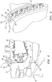
- FIG. 1 illustrates a gas turbine engine 10 which is a non-limiting example of an engine on which the system and method of the present disclosure find advantageous use.
- Engine 10 has a series of rotating components, or rotors, within a housing or casing 12. These rotating components include a fan 14 at a leading edge of engine 10, followed by low pressure compressor 16, high pressure compressor 18, a combustor 20, high pressure turbine 21 and low pressure turbine 22. These components must be balanced so that they are free of vibrations during operation. Frequently, vibrations develop during use such that various components must be balanced after use, during the various other steps to be performed in maintenance of an engine.
- Weight systems are typically used to balance the rotating components of engine 10. When the component to be balanced is at a leading or trailing edge of engine 10, the balancing system can, for the most part, be readily accessed by maintenance personnel. However, for intermediate rotating components of the engine, such as the high pressure compressor 18, as one non-limiting example, it can be difficult or impossible to access a balancing system of this component without the need for time consuming disassembly of the engine, or components thereof.
- FIG. 2 is an enlarged portion of engine 10 and shows a portion of the high pressure compressor 18 mounted within casing 12 which in this case includes an outer case 24 and an inner case 26.
- FIG. 2 also shows a weight system 28 mounted on a shaft 29 just behind the blades of high pressure compressor 18 and which can be used to balance the high pressure compressor 18 and thereby prevent vibration during operation of engine 10.
- weight system 28 has at least one weight 30 mounted within a rail 32 which extends around at least a portion of the circumference of shaft 29 behind the blades of high pressure compressor 18. Weights 30 can be held in place with a simple set screw structure or any other structure which can be accessed from outside casing 12.
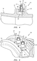
- FIG. 3 shows more detail as to how this is accomplished.
- rail 32 can be defined by a pair of radially extending walls 34 which are spaced from each other along an axis of engine 10 so as to define a weight track or space 36 therebetween.
- Walls 34 can have inwardly extending structures 38, extending toward the opposing wall, so as to define a series of ridges or otherwise defined positions at which weights 30 can be secured.
- Weights 30 have structure for being engaged by a tool, in this case outer flats 40 for engaging with a socket type tool, and also an inner structured aperture 42 for engaging with a bladed or pronged tool. These structures are for engaging weight 30 and rotating at least a portion of weight 30 between a locked position and an unlocked position. In the locked position, weight 30 is fixed within the rail. In an unlocked position, weight 30 can be moved along rail 32 so as to change the circumferential position of weight 30 relative to rotor 18. This positioning of weights 30 allows for balancing of rotor 18 against vibrations and the like.
- Fig. 3 shows rails 32 extending around a circumference of shaft 29.
- a plurality of weights 30 are shown spaced along rails 32, between walls 34, and secured in place against inwardly extending structures 38.
- Fig. 4 shows a cross section taken through one of the weights 30, for example as shown in Fig. 3 .
- Fig. 4 shows an inner structure of weight 30, wherein a weight body 48 has a diameter which extends beyond inwardly extending structures 38 of walls 34.
- a threaded portion 50 of weight 30 can be rotated relative to weight portion 48, such that portion 50 can be tightened down through the weight body 48 to the point where a bottom portion 52 of screw 50 contacts a floor within space 36, to press weight portion 48 against inwardly extending structures 38 to secure the weight in place.
- loosening screw 50 relative to weight portion 48 serves the function of unlocking the weight from the locked position, wherein the weight is secured against moving along rail 32.
- Fig. 5 shows an enlarged view similar to that of Fig. 3 , wherein weights 30 are shown secured between walls 34 of rail 30.
- weights 30 which are suitable for use in the system of the present disclosure.
- Other structures and configurations for locking and unlocking weights 28 are of course possible.
- weights 30 including how such weights are locked and unlocked can vary within the scope of the present disclosure, and this, many different configurations allowing weights to be adjusted circumferentially around rotor 18 will be apparent to a person having ordinary skill in the art.
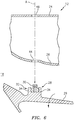
- the present system and method allow for accessing and adjusting circumferential position of one or more weights 30 while engine 10 is in an operating position, either within a test cell or installed on an aircraft. This is accomplished by positioning weight system 28 in a plane A with an inner port 44 on inner case 26 and an outer port 46 on outer case 24. This positioning of weight system 28 and ports 44, 46 allows for accessing of the weight system from outside of the engine casing 12, through ports 44, 46.
- the weight system being of the type where weights are moved circumferentially around shaft 29 allows adjustment of the weight system by unlocking and moving weights 30 along rail 32, which avoids removing and replacing of weights with other weights, and also avoids the need for specialty tools, all of which can lead to issues including the loss of tools or parts within the engine casing 12, which of course must be located and removed before any operation of the engine can take place.
- Some engine casings already have one or more ports, which can for example be borescope ports.
- ports 44, 46 are positioned in plane A along with weight system 28 such that the weight system can be accessed from outside casing 12 of engine 10, and such access is along a straight line which helps to allow adjustment of weight system 28.
- port 46 is a port which holds a fuel injector 48.
- Fuel injectors 48 can be removed from the outer case on-wing, by removing bolts 50 which secure them to outer case 24. With injector 48 removed, port 46 has ample size to allow access through port 44 to weight system 28 along a straight line (in plane A). It should also be noted that it may be desired to provide a plug for port 44 of inner case 26. This plug is to be removed from port 44 in the course of accessing weight system 28, but serves to close port 44 during operation of engine 10.
- FIG. 6 schematically illustrates a non-limiting example of operation of the system and method, in this case on an intermediate rotor, specifically the high pressure compressor 18.
- weight system 28 is mounted on a shaft 29 behind the rotor of the high pressure compressor 18, in this case downstream or behind the location of blades on the rotor.
- This is advantageous in that it allows rail 32 to extend around an entire circumference of shaft 29, rather than between blades of the rotor, such that adjustment of position of a weight within the rail can be accomplished without needing to disassemble blades.
- rail 32 is positioned in a plane A, perpendicular to axis X of engine 10, with inner port 44 of inner case 26 also located in plane A, and also with outer port 46 of outer case 24 in plane A.
- weight system 28 needs to be adjusted, plugs, fuel injectors or other structures or devices can be removed from ports 44, 46, and an implement can be extended through ports 44, 46 to engage a weight 30, for example by engaging either flats 40 or aperture 42 of weight 30.
- Weights 30 are then manipulated with the tool, in this case through rotation, to move from a locked position to an unlocked position within rail 32.
- the rotor In an unlocked position, and while the unlocked weight remains engaged with the tool, the rotor can be slowly rotated such that the rotor rotates while weight 30 stays in place. This results in circumferential movement of weight 30, through rail 32, relative to shaft 29 and the rotor.
- the high pressure compressor of such an engine has a rear plane trim balance weight feature comprising a slotted rail at the aft end of the HPC Rear Hub.
- This type of adjustable weight system is well suited for use in the present disclosure.
- a moveable weight with a locking set screw mounted in a circumferential rail allows the HPC rotor trim balance to be adjusted by changing the circumferential position of the weight in the rail.
- changes to the design of one or more of the inner case 26, or inner diffuser case, the outer case 24, and the high pressure compressor (HPC) rear hub can make the trim balance feature accessible from the outside without disassembly of the engine.
- the change to the inner case 26 could be, as a non-limiting example, to incorporate a boss that would accommodate a borescope plug that would be located in the axial gap between the aft end of the diffuser and in front of the combustor.
- the balance feature i.e. rail 32
- no change is required to the outer case 24, as port 46 is already in place in a desirable location.
- inner port 44 and weight system 28 can be positioned to align in a plane (plane A) with outer port 46.
- access to access port 44 in the inner case 26 can be gained by removing a fuel nozzle
- access ports are being added to facilitate the present disclosure, it can be desirable to locate new access ports near the 3:00 or 9:00 position to facilitate access when the engine is either on-wing or in a test cell.
- permanent index reference marks can be added to the balance slot to facilitate adjustments to the position of the weights.
- Such index reference marks could be provided as shallow round-bottom holes or dimples, or the like, since such features will not cause a local increase in stress.
- One possible application of this concept would be to add two equal weights positioned 180 degrees apart when assembling the high pressure compressor (HPC) rotor. These two weights would be installed in addition to the weight used to complete the HPC rotor trim balance. They would not affect the balance of the rotor during initial assembly and balance but they would be available to trim the engine after it begins testing or operation.
- HPC high pressure compressor
- the proposed disclosure can be incorporated in current engine designs as a product upgrade.
- the number of parts that require redesign to incorporate this capability is limited.
- the concept could also be incorporated in new designs.
Landscapes
- Engineering & Computer Science (AREA)
- General Engineering & Computer Science (AREA)
- Mechanical Engineering (AREA)
- Chemical & Material Sciences (AREA)
- Combustion & Propulsion (AREA)
- Physics & Mathematics (AREA)
- Acoustics & Sound (AREA)
- Aviation & Aerospace Engineering (AREA)
- Structures Of Non-Positive Displacement Pumps (AREA)
- Turbine Rotor Nozzle Sealing (AREA)
Claims (8)
- Auswuchtsystem für ein zusammengesetztes Triebwerk (10) mit einer Triebwerksachse (X), das Folgendes umfasst:einen Triebwerksmantel (12), der eine Welle (29), ein Innengehäuse (26) und ein Außengehäuse (24) aufweist;einen Rotor (14; 16; 18; 21; 22), der an der Welle (29) zur Rotation innerhalb des Triebwerksmantels (12) angebracht ist; undein Gewichtssystem (28), das an der Welle (29) des Rotors (14...22) angebracht ist und mindestens ein Gewicht (30) aufweist, das relativ zum Rotor (14...22) um einen Umfang der Welle (29) angeordnet werden kann;wobei das Innengehäuse (26) eine innere Zugangsöffnung (44) aufweist, das Außengehäuse (24) eine äußere Zugangsöffnung (46) aufweist und die innere Zugangsöffnung (44), die äußere Zugangsöffnung (46) und das Gewichtssystem (28) auf derselben radialen Ebene (A) der Welle (29) angeordnet sind, wobei die radiale Ebene (A) senkrecht zur Triebwerksachse (X) ist, wobei auf das Gewichtssystem (28) durch die äußere Zugangsöffnung (46) und die innere Zugangsöffnung (44) zugegriffen werden kann, um eine Umfangsposition des mindestens einen Gewichts (30) relativ zur Welle (29) anzupassen,wobei das Gewichtssystem (28) eine Schiene (32) umfasst, die um mindestens einen Abschnitt des Umfangs der Welle (29) angebracht ist, und wobei das mindestens eine Gewicht (30) an der Schiene (32) angebracht ist und eine Verriegelungsstruktur zum Verriegeln des Gewichts (30) in Position relativ zur Schiene (32) aufweist, wobei die Verriegelungsstruktur durch die innere Zugangsöffnung (44) und die äußere Zugangsöffnung (46) verriegelt und entriegelt werden kann, wobei, wenn die Verriegelungsstruktur entriegelt ist, das mindestens eine Gewicht (30) entlang der Schiene (32) bewegt werden kann, und wenn die Verriegelungsstruktur verriegelt ist, das mindestens eine Gewicht (30) in Position an der Schiene (32) fixiert ist, wobei auf das mindestens eine Gewicht (30) von außerhalb des Triebwerksmantels (12) in einer geraden Linie durch die äußere Zugangsöffnung (46) und die innere Zugangsöffnung (44) zugegriffen werden kann,wobei die innere Zugangsöffnung (44) eine Boroskopöffnung ist,dadurch gekennzeichnet, dassdie äußere Zugangsöffnung (46) eine Kraftstoffeinspritzöffnung (46) ist.
- Verfahren zum Auswuchten eines Rotors (14...22) für ein zusammengesetztes Triebwerk (10) mit einer Achse (X), die folgenden Schritte umfassend:Zugreifen auf ein Gewichtssystem (28) eines Rotors (14...22), der an einer Welle (29) zur Rotation innerhalb eines Triebwerksmantels (12) angebracht ist, der ein Innengehäuse (26) und ein Außengehäuse (24) aufweist, wobei das eine Gewichtssystem (28) an der Welle (29) angebracht ist undmindestens ein Gewicht (30) aufweist, das relativ zum Rotor (14...22) um einen Umfang der Welle (29) angeordnet werden kann, wobei das Innengehäuse (26) eine innere Zugangsöffnung (44) aufweist, das Außengehäuse (24) eine äußere Zugangsöffnung (46) aufweist und die innere Zugangsöffnung (44), die äußere Zugangsöffnung (46) und das Gewichtssystem (28) auf derselben radialen Ebene (A) des Rotors (14...22) und entlang einer geraden Linie angeordnet sind, wobei die radiale Ebene (A) senkrecht zur Triebwerksachse (X) ist; undVerändern der Umfangsposition des mindestens einen Gewichts (30) relativ zur Welle (29),wobei das Gewichtssystem (28) eine Schiene (32) umfasst, die um mindestens einen Abschnitt des Umfangs der Welle (29) angebracht ist, und wobei das mindestens eine Gewicht (30) an der Schiene (32) angebracht ist und eine Verriegelungsstruktur zum Verriegeln des Gewichts (30) in Position relativ zur Schiene (32) aufweist, wobei die Verriegelungsstruktur durch die innere Zugangsöffnung (44) und die äußere Zugangsöffnung (46) verriegelt und entriegelt werden kann, wobei das Verfahren ferner die folgenden Schritte umfasst:Zugreifen auf die Verriegelungsstruktur von außerhalb des Triebwerksmantels (12) durch die äußere Zugangsöffnung (46) und die innere Zugangsöffnung (44);Entriegeln der Verriegelungsstruktur;Bewegen des mindestens einen Gewichts (30) entlang der Schiene (32) auf eine andere Umfangsposition relativ zur Welle (29); und Verriegeln der Verriegelungsstruktur,wobei die innere Zugangsöffnung (44) eine Boroskopöffnung ist und die äußere Zugangsöffnung (46) eine Kraftstoffeinspritzöffnung (46) ist, und ferner den Schritt des Entfernens eines Kraftstoffeinspritzers (48) aus der Kraftstoffeinspritzöffnung (46) umfassend, um den Zugriff durch die Kraftstoffeinspritzöffnung (46) zu ermöglichen.
- Verfahren nach Anspruch 2, wobei der Schritt des Entriegelns das Entriegeln der Verriegelungsstruktur mit einem Werkzeug, das von außerhalb des Triebwerksmantels (12) durch die äußere Zugangsöffnung (46) und die innere Zugangsöffnung (44) eingesetzt wird, umfasst und wobei der Schritt des Bewegens das Halten des mindestens einen Gewichts (30) in Position mit dem Werkzeug, während der Rotor (14...22) gedreht wird, umfasst, um so das mindestens eine Gewicht (30) in die andere Umfangsposition zu bewegen.
- Verfahren oder System nach einem der vorstehenden Ansprüche, wobei der Rotor (14...22) eine Vielzahl von Laufschaufeln aufweist, die um die Welle (29) angebracht sind, und wobei das Gewichtssystem (28) axial von den Laufschaufeln beabstandet ist.
- Verfahren oder System nach einem der vorstehenden Ansprüche, wobei das Triebwerk (10) ein Gasturbinentriebwerk (10) ist und wobei der Rotor (18; 21) ein Hochgeschwindigkeitsrotor (18; 21) des Gasturbinentriebwerks (10) ist.
- Verfahren oder System nach Anspruch 5, wobei der Rotor (18) ein Hochdruckverdichter (18) des Triebwerks (10) ist.
- Verfahren oder System nach einem der vorstehenden Ansprüche, wobei das Triebwerk (10) eine Vielzahl von Rotoren (14, 16, 18, 21, 22) aufweist, die entlang der Achse (X) des Triebwerks (10) angeordnet sind, und wobei der Rotor (16; 18; 21) ein Zwischenrotor (16 ; 18; 21) entlang der Achse (X) ist.
- Verfahren nach einem der Ansprüche 2 bis 7, wobei die Schritte des Zugreifens und Veränderns durchgeführt werden, während sich der Rotor (14; 16; 18; 21; 22) in einer Betriebsposition innerhalb des Triebwerksmantels (12) befindet.
Applications Claiming Priority (1)
| Application Number | Priority Date | Filing Date | Title |
|---|---|---|---|
| US16/014,214 US10954793B2 (en) | 2018-06-21 | 2018-06-21 | System and method for balancing a rotor in an assembled engine |
Publications (3)
| Publication Number | Publication Date |
|---|---|
| EP3587733A1 EP3587733A1 (de) | 2020-01-01 |
| EP3587733B1 true EP3587733B1 (de) | 2021-01-20 |
| EP3587733B8 EP3587733B8 (de) | 2021-04-07 |
Family
ID=66998210
Family Applications (1)
| Application Number | Title | Priority Date | Filing Date |
|---|---|---|---|
| EP19181006.8A Active EP3587733B8 (de) | 2018-06-21 | 2019-06-18 | System und verfahren zum auswuchten eines rotors in einem zusammengesetzten motor |
Country Status (2)
| Country | Link |
|---|---|
| US (1) | US10954793B2 (de) |
| EP (1) | EP3587733B8 (de) |
Families Citing this family (7)
| Publication number | Priority date | Publication date | Assignee | Title |
|---|---|---|---|---|
| CN113944548B (zh) * | 2020-07-16 | 2022-09-20 | 宝山钢铁股份有限公司 | 燃气轮机联合循环机组单轴轴系功能的可靠性提高方法 |
| US11377955B2 (en) | 2020-09-16 | 2022-07-05 | General Electric Company | Balancing weight entry port for turbine rotor |
| US11732585B2 (en) * | 2021-01-28 | 2023-08-22 | General Electric Company | Trapped rotatable weights to improve rotor balance |
| CN116773088B (zh) * | 2023-06-16 | 2024-09-03 | 中国航空发动机研究院 | 一种发动机转子平衡系统及方法和发动机 |
| CN118836188A (zh) * | 2024-07-12 | 2024-10-25 | 中国航发沈阳发动机研究所 | 一种航空发动机压气机转子平衡结构 |
| US12601263B1 (en) * | 2024-11-26 | 2026-04-14 | Pratt & Whitney Canada Corp. | Radially captured in situ balancing masses for aircraft powerplant |
| US12553346B1 (en) | 2025-03-10 | 2026-02-17 | Pratt & Whitney Canada Corp. | Gas turbine engine with rotational spool balancing system |
Family Cites Families (9)
| Publication number | Priority date | Publication date | Assignee | Title |
|---|---|---|---|---|
| FR2630496B1 (fr) | 1988-04-20 | 1993-05-14 | Snecma | Dispositif de correction de balourd d'un rotor de turbomachine |
| US5545010A (en) * | 1993-05-13 | 1996-08-13 | Solar Turbines Incorporated | Method and apparatus for trim balancing a gas turbine engine |
| US6279420B1 (en) | 1999-08-18 | 2001-08-28 | General Electric Co. | Balance weight for a rotary component in turbomachinery, methods of installation and installation tools |
| US20050265846A1 (en) | 2004-06-01 | 2005-12-01 | Przytulski James C | Balance assembly for rotary turbine component and method for installing and/or adjusting balance weight |
| US7465146B2 (en) | 2005-12-05 | 2008-12-16 | General Electric Company | Methods and systems for turbine rotor balancing |
| US9127555B2 (en) * | 2010-12-21 | 2015-09-08 | Solar Turbines Incorporated | Method for balancing rotating assembly of gas turbine engine |
| DE102011100783A1 (de) * | 2011-05-06 | 2012-11-08 | Rolls-Royce Deutschland Ltd & Co Kg | Gasturbinenauswuchtvorrichtung |
| GB201409245D0 (en) * | 2014-05-23 | 2014-07-09 | Rolls Royce Plc | Rotor balancing |
| US10316666B2 (en) * | 2016-04-12 | 2019-06-11 | General Electric Company | System and method for in situ balancing of a rotating component of a gas turbine engine |
-
2018
- 2018-06-21 US US16/014,214 patent/US10954793B2/en active Active
-
2019
- 2019-06-18 EP EP19181006.8A patent/EP3587733B8/de active Active
Non-Patent Citations (1)
| Title |
|---|
| None * |
Also Published As
| Publication number | Publication date |
|---|---|
| EP3587733B8 (de) | 2021-04-07 |
| US20190390552A1 (en) | 2019-12-26 |
| US10954793B2 (en) | 2021-03-23 |
| EP3587733A1 (de) | 2020-01-01 |
Similar Documents
| Publication | Publication Date | Title |
|---|---|---|
| EP3587733B1 (de) | System und verfahren zum auswuchten eines rotors in einem zusammengesetzten motor | |
| EP2964886B1 (de) | Scheibenanordnung und verfahren zum halten zweier separater rotierender elemente eines gasturbinenmotors | |
| EP2447472B1 (de) | Trimmungsausgleich für Gasturbinenmotor | |
| US8246305B2 (en) | Gas turbine engine balancing | |
| US9127555B2 (en) | Method for balancing rotating assembly of gas turbine engine | |
| EP3049624B1 (de) | Wuchtring für ein rotierendes bauteil | |
| JPS591337B2 (ja) | タ−ビンを取替える方法 | |
| US9017029B2 (en) | Gas-turbine balancing device | |
| US10436224B2 (en) | Method and apparatus for balancing a rotor | |
| GB2457060A (en) | Rotor with balance mass | |
| US20150267614A1 (en) | Turbine engine cowl capable of covering a fan cone | |
| EP2565384B1 (de) | Beschaufelter Rotor und zugehöriges Montageverfahren | |
| US10883384B2 (en) | Arm for turbomachine casing comprising a body and a removable part | |
| EP3647541B1 (de) | Vernier-spaltring für turbinenrotorstapelanordnung | |
| US20240183273A1 (en) | Rotor balancing apparatus | |
| US10883370B2 (en) | Dovetail weight system for rotor balance | |
| US9045984B2 (en) | Stator vane mistake proofing | |
| CN108661727B (zh) | 涡轮发动机轴承组件及其组装方法 | |
| CN114962002B (zh) | 带有弹性支撑的轴承组件及航空发动机 | |
| CN114402121B (zh) | 用于涡轮机的组合件 | |
| EP4134524B1 (de) | Turbomaschinenbauteile mit kronenflanschen und verfahren zum verbinden von turbomaschinenbauteilen | |
| US20260078767A1 (en) | Assembly comprising a ring and a pivoting support sleeve for variable pitch vane roots, turbine engine provided with such an assembly and method for dismantling such an assembly |
Legal Events
| Date | Code | Title | Description |
|---|---|---|---|
| PUAI | Public reference made under article 153(3) epc to a published international application that has entered the european phase |
Free format text: ORIGINAL CODE: 0009012 |
|
| STAA | Information on the status of an ep patent application or granted ep patent |
Free format text: STATUS: THE APPLICATION HAS BEEN PUBLISHED |
|
| AK | Designated contracting states |
Kind code of ref document: A1 Designated state(s): AL AT BE BG CH CY CZ DE DK EE ES FI FR GB GR HR HU IE IS IT LI LT LU LV MC MK MT NL NO PL PT RO RS SE SI SK SM TR |
|
| AX | Request for extension of the european patent |
Extension state: BA ME |
|
| STAA | Information on the status of an ep patent application or granted ep patent |
Free format text: STATUS: REQUEST FOR EXAMINATION WAS MADE |
|
| 17P | Request for examination filed |
Effective date: 20200701 |
|
| RBV | Designated contracting states (corrected) |
Designated state(s): AL AT BE BG CH CY CZ DE DK EE ES FI FR GB GR HR HU IE IS IT LI LT LU LV MC MK MT NL NO PL PT RO RS SE SI SK SM TR |
|
| GRAP | Despatch of communication of intention to grant a patent |
Free format text: ORIGINAL CODE: EPIDOSNIGR1 |
|
| STAA | Information on the status of an ep patent application or granted ep patent |
Free format text: STATUS: GRANT OF PATENT IS INTENDED |
|
| RIC1 | Information provided on ipc code assigned before grant |
Ipc: F04D 29/66 20060101ALI20200716BHEP Ipc: F01D 5/02 20060101AFI20200716BHEP |
|
| INTG | Intention to grant announced |
Effective date: 20200810 |
|
| GRAS | Grant fee paid |
Free format text: ORIGINAL CODE: EPIDOSNIGR3 |
|
| GRAA | (expected) grant |
Free format text: ORIGINAL CODE: 0009210 |
|
| STAA | Information on the status of an ep patent application or granted ep patent |
Free format text: STATUS: THE PATENT HAS BEEN GRANTED |
|
| AK | Designated contracting states |
Kind code of ref document: B1 Designated state(s): AL AT BE BG CH CY CZ DE DK EE ES FI FR GB GR HR HU IE IS IT LI LT LU LV MC MK MT NL NO PL PT RO RS SE SI SK SM TR |
|
| REG | Reference to a national code |
Ref country code: GB Ref legal event code: FG4D |
|
| REG | Reference to a national code |
Ref country code: CH Ref legal event code: EP |
|
| REG | Reference to a national code |
Ref country code: DE Ref legal event code: R096 Ref document number: 602019002263 Country of ref document: DE |
|
| REG | Reference to a national code |
Ref country code: AT Ref legal event code: REF Ref document number: 1356563 Country of ref document: AT Kind code of ref document: T Effective date: 20210215 |
|
| REG | Reference to a national code |
Ref country code: IE Ref legal event code: FG4D |
|
| REG | Reference to a national code |
Ref country code: DE Ref legal event code: R081 Ref document number: 602019002263 Country of ref document: DE Owner name: RAYTHEON TECHNOLOGIES CORPORATION, FARMINGTON, US Free format text: FORMER OWNER: UNITED TECHNOLOGIES CORPORATION, FARMINGTON, CONN., US Ref country code: DE Ref legal event code: R081 Ref document number: 602019002263 Country of ref document: DE Owner name: RTX CORPORATION (N.D.GES.D. STAATES DELAWARE),, US Free format text: FORMER OWNER: UNITED TECHNOLOGIES CORPORATION, FARMINGTON, CONN., US |
|
| REG | Reference to a national code |
Ref country code: CH Ref legal event code: PK Free format text: BERICHTIGUNG B8 |
|
| RAP2 | Party data changed (patent owner data changed or rights of a patent transferred) |
Owner name: RAYTHEON TECHNOLOGIES CORPORATION |
|
| REG | Reference to a national code |
Ref country code: NL Ref legal event code: MP Effective date: 20210120 |
|
| REG | Reference to a national code |
Ref country code: LT Ref legal event code: MG9D |
|
| REG | Reference to a national code |
Ref country code: AT Ref legal event code: MK05 Ref document number: 1356563 Country of ref document: AT Kind code of ref document: T Effective date: 20210120 |
|
| PG25 | Lapsed in a contracting state [announced via postgrant information from national office to epo] |
Ref country code: HR Free format text: LAPSE BECAUSE OF FAILURE TO SUBMIT A TRANSLATION OF THE DESCRIPTION OR TO PAY THE FEE WITHIN THE PRESCRIBED TIME-LIMIT Effective date: 20210120 Ref country code: BG Free format text: LAPSE BECAUSE OF FAILURE TO SUBMIT A TRANSLATION OF THE DESCRIPTION OR TO PAY THE FEE WITHIN THE PRESCRIBED TIME-LIMIT Effective date: 20210420 Ref country code: FI Free format text: LAPSE BECAUSE OF FAILURE TO SUBMIT A TRANSLATION OF THE DESCRIPTION OR TO PAY THE FEE WITHIN THE PRESCRIBED TIME-LIMIT Effective date: 20210120 Ref country code: GR Free format text: LAPSE BECAUSE OF FAILURE TO SUBMIT A TRANSLATION OF THE DESCRIPTION OR TO PAY THE FEE WITHIN THE PRESCRIBED TIME-LIMIT Effective date: 20210421 Ref country code: NO Free format text: LAPSE BECAUSE OF FAILURE TO SUBMIT A TRANSLATION OF THE DESCRIPTION OR TO PAY THE FEE WITHIN THE PRESCRIBED TIME-LIMIT Effective date: 20210420 Ref country code: PT Free format text: LAPSE BECAUSE OF FAILURE TO SUBMIT A TRANSLATION OF THE DESCRIPTION OR TO PAY THE FEE WITHIN THE PRESCRIBED TIME-LIMIT Effective date: 20210520 Ref country code: LT Free format text: LAPSE BECAUSE OF FAILURE TO SUBMIT A TRANSLATION OF THE DESCRIPTION OR TO PAY THE FEE WITHIN THE PRESCRIBED TIME-LIMIT Effective date: 20210120 |
|
| PG25 | Lapsed in a contracting state [announced via postgrant information from national office to epo] |
Ref country code: LV Free format text: LAPSE BECAUSE OF FAILURE TO SUBMIT A TRANSLATION OF THE DESCRIPTION OR TO PAY THE FEE WITHIN THE PRESCRIBED TIME-LIMIT Effective date: 20210120 Ref country code: PL Free format text: LAPSE BECAUSE OF FAILURE TO SUBMIT A TRANSLATION OF THE DESCRIPTION OR TO PAY THE FEE WITHIN THE PRESCRIBED TIME-LIMIT Effective date: 20210120 Ref country code: AT Free format text: LAPSE BECAUSE OF FAILURE TO SUBMIT A TRANSLATION OF THE DESCRIPTION OR TO PAY THE FEE WITHIN THE PRESCRIBED TIME-LIMIT Effective date: 20210120 Ref country code: SE Free format text: LAPSE BECAUSE OF FAILURE TO SUBMIT A TRANSLATION OF THE DESCRIPTION OR TO PAY THE FEE WITHIN THE PRESCRIBED TIME-LIMIT Effective date: 20210120 Ref country code: RS Free format text: LAPSE BECAUSE OF FAILURE TO SUBMIT A TRANSLATION OF THE DESCRIPTION OR TO PAY THE FEE WITHIN THE PRESCRIBED TIME-LIMIT Effective date: 20210120 |
|
| PG25 | Lapsed in a contracting state [announced via postgrant information from national office to epo] |
Ref country code: IS Free format text: LAPSE BECAUSE OF FAILURE TO SUBMIT A TRANSLATION OF THE DESCRIPTION OR TO PAY THE FEE WITHIN THE PRESCRIBED TIME-LIMIT Effective date: 20210520 |
|
| REG | Reference to a national code |
Ref country code: DE Ref legal event code: R097 Ref document number: 602019002263 Country of ref document: DE |
|
| PG25 | Lapsed in a contracting state [announced via postgrant information from national office to epo] |
Ref country code: SM Free format text: LAPSE BECAUSE OF FAILURE TO SUBMIT A TRANSLATION OF THE DESCRIPTION OR TO PAY THE FEE WITHIN THE PRESCRIBED TIME-LIMIT Effective date: 20210120 Ref country code: CZ Free format text: LAPSE BECAUSE OF FAILURE TO SUBMIT A TRANSLATION OF THE DESCRIPTION OR TO PAY THE FEE WITHIN THE PRESCRIBED TIME-LIMIT Effective date: 20210120 Ref country code: EE Free format text: LAPSE BECAUSE OF FAILURE TO SUBMIT A TRANSLATION OF THE DESCRIPTION OR TO PAY THE FEE WITHIN THE PRESCRIBED TIME-LIMIT Effective date: 20210120 |
|
| PLBE | No opposition filed within time limit |
Free format text: ORIGINAL CODE: 0009261 |
|
| STAA | Information on the status of an ep patent application or granted ep patent |
Free format text: STATUS: NO OPPOSITION FILED WITHIN TIME LIMIT |
|
| PG25 | Lapsed in a contracting state [announced via postgrant information from national office to epo] |
Ref country code: SK Free format text: LAPSE BECAUSE OF FAILURE TO SUBMIT A TRANSLATION OF THE DESCRIPTION OR TO PAY THE FEE WITHIN THE PRESCRIBED TIME-LIMIT Effective date: 20210120 Ref country code: RO Free format text: LAPSE BECAUSE OF FAILURE TO SUBMIT A TRANSLATION OF THE DESCRIPTION OR TO PAY THE FEE WITHIN THE PRESCRIBED TIME-LIMIT Effective date: 20210120 Ref country code: DK Free format text: LAPSE BECAUSE OF FAILURE TO SUBMIT A TRANSLATION OF THE DESCRIPTION OR TO PAY THE FEE WITHIN THE PRESCRIBED TIME-LIMIT Effective date: 20210120 |
|
| 26N | No opposition filed |
Effective date: 20211021 |
|
| PG25 | Lapsed in a contracting state [announced via postgrant information from national office to epo] |
Ref country code: ES Free format text: LAPSE BECAUSE OF FAILURE TO SUBMIT A TRANSLATION OF THE DESCRIPTION OR TO PAY THE FEE WITHIN THE PRESCRIBED TIME-LIMIT Effective date: 20210120 Ref country code: MC Free format text: LAPSE BECAUSE OF FAILURE TO SUBMIT A TRANSLATION OF THE DESCRIPTION OR TO PAY THE FEE WITHIN THE PRESCRIBED TIME-LIMIT Effective date: 20210120 Ref country code: AL Free format text: LAPSE BECAUSE OF FAILURE TO SUBMIT A TRANSLATION OF THE DESCRIPTION OR TO PAY THE FEE WITHIN THE PRESCRIBED TIME-LIMIT Effective date: 20210120 |
|
| PG25 | Lapsed in a contracting state [announced via postgrant information from national office to epo] |
Ref country code: SI Free format text: LAPSE BECAUSE OF FAILURE TO SUBMIT A TRANSLATION OF THE DESCRIPTION OR TO PAY THE FEE WITHIN THE PRESCRIBED TIME-LIMIT Effective date: 20210120 |
|
| REG | Reference to a national code |
Ref country code: BE Ref legal event code: MM Effective date: 20210630 |
|
| PG25 | Lapsed in a contracting state [announced via postgrant information from national office to epo] |
Ref country code: LU Free format text: LAPSE BECAUSE OF NON-PAYMENT OF DUE FEES Effective date: 20210618 |
|
| PG25 | Lapsed in a contracting state [announced via postgrant information from national office to epo] |
Ref country code: IT Free format text: LAPSE BECAUSE OF FAILURE TO SUBMIT A TRANSLATION OF THE DESCRIPTION OR TO PAY THE FEE WITHIN THE PRESCRIBED TIME-LIMIT Effective date: 20210120 Ref country code: IE Free format text: LAPSE BECAUSE OF NON-PAYMENT OF DUE FEES Effective date: 20210618 |
|
| PG25 | Lapsed in a contracting state [announced via postgrant information from national office to epo] |
Ref country code: IS Free format text: LAPSE BECAUSE OF FAILURE TO SUBMIT A TRANSLATION OF THE DESCRIPTION OR TO PAY THE FEE WITHIN THE PRESCRIBED TIME-LIMIT Effective date: 20210520 |
|
| PG25 | Lapsed in a contracting state [announced via postgrant information from national office to epo] |
Ref country code: BE Free format text: LAPSE BECAUSE OF NON-PAYMENT OF DUE FEES Effective date: 20210630 |
|
| REG | Reference to a national code |
Ref country code: CH Ref legal event code: PL |
|
| PG25 | Lapsed in a contracting state [announced via postgrant information from national office to epo] |
Ref country code: LI Free format text: LAPSE BECAUSE OF NON-PAYMENT OF DUE FEES Effective date: 20220630 Ref country code: CH Free format text: LAPSE BECAUSE OF NON-PAYMENT OF DUE FEES Effective date: 20220630 |
|
| P01 | Opt-out of the competence of the unified patent court (upc) registered |
Effective date: 20230521 |
|
| PG25 | Lapsed in a contracting state [announced via postgrant information from national office to epo] |
Ref country code: NL Free format text: LAPSE BECAUSE OF NON-PAYMENT OF DUE FEES Effective date: 20210120 Ref country code: CY Free format text: LAPSE BECAUSE OF FAILURE TO SUBMIT A TRANSLATION OF THE DESCRIPTION OR TO PAY THE FEE WITHIN THE PRESCRIBED TIME-LIMIT Effective date: 20210120 |
|
| PG25 | Lapsed in a contracting state [announced via postgrant information from national office to epo] |
Ref country code: HU Free format text: LAPSE BECAUSE OF FAILURE TO SUBMIT A TRANSLATION OF THE DESCRIPTION OR TO PAY THE FEE WITHIN THE PRESCRIBED TIME-LIMIT; INVALID AB INITIO Effective date: 20190618 |
|
| PG25 | Lapsed in a contracting state [announced via postgrant information from national office to epo] |
Ref country code: MK Free format text: LAPSE BECAUSE OF FAILURE TO SUBMIT A TRANSLATION OF THE DESCRIPTION OR TO PAY THE FEE WITHIN THE PRESCRIBED TIME-LIMIT Effective date: 20210120 |
|
| PG25 | Lapsed in a contracting state [announced via postgrant information from national office to epo] |
Ref country code: MT Free format text: LAPSE BECAUSE OF FAILURE TO SUBMIT A TRANSLATION OF THE DESCRIPTION OR TO PAY THE FEE WITHIN THE PRESCRIBED TIME-LIMIT Effective date: 20210120 |
|
| PGFP | Annual fee paid to national office [announced via postgrant information from national office to epo] |
Ref country code: DE Payment date: 20250520 Year of fee payment: 7 |
|
| PGFP | Annual fee paid to national office [announced via postgrant information from national office to epo] |
Ref country code: GB Payment date: 20250520 Year of fee payment: 7 |
|
| PGFP | Annual fee paid to national office [announced via postgrant information from national office to epo] |
Ref country code: FR Payment date: 20250520 Year of fee payment: 7 |
|
| REG | Reference to a national code |
Ref country code: DE Ref legal event code: R081 Ref document number: 602019002263 Country of ref document: DE Owner name: RTX CORPORATION (N.D.GES.D. STAATES DELAWARE),, US Free format text: FORMER OWNER: RAYTHEON TECHNOLOGIES CORPORATION, FARMINGTON, CT, US |
|
| PG25 | Lapsed in a contracting state [announced via postgrant information from national office to epo] |
Ref country code: TR Free format text: LAPSE BECAUSE OF FAILURE TO SUBMIT A TRANSLATION OF THE DESCRIPTION OR TO PAY THE FEE WITHIN THE PRESCRIBED TIME-LIMIT Effective date: 20210120 |