EP3587774B1 - Turbine à gaz - Google Patents
Turbine à gaz Download PDFInfo
- Publication number
- EP3587774B1 EP3587774B1 EP19182050.5A EP19182050A EP3587774B1 EP 3587774 B1 EP3587774 B1 EP 3587774B1 EP 19182050 A EP19182050 A EP 19182050A EP 3587774 B1 EP3587774 B1 EP 3587774B1
- Authority
- EP
- European Patent Office
- Prior art keywords
- gas turbine
- fan
- gearbox
- shaft
- bearing system
- Prior art date
- Legal status (The legal status is an assumption and is not a legal conclusion. Google has not performed a legal analysis and makes no representation as to the accuracy of the status listed.)
- Active
Links
Images


Classifications
-
- F—MECHANICAL ENGINEERING; LIGHTING; HEATING; WEAPONS; BLASTING
- F01—MACHINES OR ENGINES IN GENERAL; ENGINE PLANTS IN GENERAL; STEAM ENGINES
- F01D—NON-POSITIVE DISPLACEMENT MACHINES OR ENGINES, e.g. STEAM TURBINES
- F01D15/00—Adaptations of machines or engines for special use; Combinations of engines with devices driven thereby
- F01D15/12—Combinations with mechanical gearing
-
- F—MECHANICAL ENGINEERING; LIGHTING; HEATING; WEAPONS; BLASTING
- F01—MACHINES OR ENGINES IN GENERAL; ENGINE PLANTS IN GENERAL; STEAM ENGINES
- F01D—NON-POSITIVE DISPLACEMENT MACHINES OR ENGINES, e.g. STEAM TURBINES
- F01D25/00—Component parts, details, or accessories, not provided for in, or of interest apart from, other groups
- F01D25/16—Arrangement of bearings; Supporting or mounting bearings in casings
-
- F—MECHANICAL ENGINEERING; LIGHTING; HEATING; WEAPONS; BLASTING
- F01—MACHINES OR ENGINES IN GENERAL; ENGINE PLANTS IN GENERAL; STEAM ENGINES
- F01D—NON-POSITIVE DISPLACEMENT MACHINES OR ENGINES, e.g. STEAM TURBINES
- F01D25/00—Component parts, details, or accessories, not provided for in, or of interest apart from, other groups
- F01D25/34—Turning or inching gear
-
- F—MECHANICAL ENGINEERING; LIGHTING; HEATING; WEAPONS; BLASTING
- F02—COMBUSTION ENGINES; HOT-GAS OR COMBUSTION-PRODUCT ENGINE PLANTS
- F02C—GAS-TURBINE PLANTS; AIR INTAKES FOR JET-PROPULSION PLANTS; CONTROLLING FUEL SUPPLY IN AIR-BREATHING JET-PROPULSION PLANTS
- F02C7/00—Features, components parts, details or accessories, not provided for in, or of interest apart form groups F02C1/00 - F02C6/00; Air intakes for jet-propulsion plants
- F02C7/36—Power transmission arrangements between the different shafts of the gas turbine plant, or between the gas-turbine plant and the power user
-
- F—MECHANICAL ENGINEERING; LIGHTING; HEATING; WEAPONS; BLASTING
- F02—COMBUSTION ENGINES; HOT-GAS OR COMBUSTION-PRODUCT ENGINE PLANTS
- F02K—JET-PROPULSION PLANTS
- F02K3/00—Plants including a gas turbine driving a compressor or a ducted fan
- F02K3/02—Plants including a gas turbine driving a compressor or a ducted fan in which part of the working fluid by-passes the turbine and combustion chamber
- F02K3/04—Plants including a gas turbine driving a compressor or a ducted fan in which part of the working fluid by-passes the turbine and combustion chamber the plant including ducted fans, i.e. fans with high volume, low pressure outputs, for augmenting the jet thrust, e.g. of double-flow type
- F02K3/06—Plants including a gas turbine driving a compressor or a ducted fan in which part of the working fluid by-passes the turbine and combustion chamber the plant including ducted fans, i.e. fans with high volume, low pressure outputs, for augmenting the jet thrust, e.g. of double-flow type with front fan
-
- F—MECHANICAL ENGINEERING; LIGHTING; HEATING; WEAPONS; BLASTING
- F16—ENGINEERING ELEMENTS AND UNITS; GENERAL MEASURES FOR PRODUCING AND MAINTAINING EFFECTIVE FUNCTIONING OF MACHINES OR INSTALLATIONS; THERMAL INSULATION IN GENERAL
- F16H—GEARING
- F16H1/00—Toothed gearings for conveying rotary motion
- F16H1/28—Toothed gearings for conveying rotary motion with gears having orbital motion
-
- F—MECHANICAL ENGINEERING; LIGHTING; HEATING; WEAPONS; BLASTING
- F16—ENGINEERING ELEMENTS AND UNITS; GENERAL MEASURES FOR PRODUCING AND MAINTAINING EFFECTIVE FUNCTIONING OF MACHINES OR INSTALLATIONS; THERMAL INSULATION IN GENERAL
- F16H—GEARING
- F16H57/00—General details of gearing
- F16H57/08—General details of gearing of gearings with members having orbital motion
- F16H57/082—Planet carriers
-
- F—MECHANICAL ENGINEERING; LIGHTING; HEATING; WEAPONS; BLASTING
- F01—MACHINES OR ENGINES IN GENERAL; ENGINE PLANTS IN GENERAL; STEAM ENGINES
- F01D—NON-POSITIVE DISPLACEMENT MACHINES OR ENGINES, e.g. STEAM TURBINES
- F01D25/00—Component parts, details, or accessories, not provided for in, or of interest apart from, other groups
- F01D25/16—Arrangement of bearings; Supporting or mounting bearings in casings
- F01D25/162—Bearing supports
-
- F—MECHANICAL ENGINEERING; LIGHTING; HEATING; WEAPONS; BLASTING
- F01—MACHINES OR ENGINES IN GENERAL; ENGINE PLANTS IN GENERAL; STEAM ENGINES
- F01D—NON-POSITIVE DISPLACEMENT MACHINES OR ENGINES, e.g. STEAM TURBINES
- F01D5/00—Blades; Blade-carrying members; Heating, heat-insulating, cooling or antivibration means on the blades or the members
- F01D5/02—Blade-carrying members, e.g. rotors
-
- F—MECHANICAL ENGINEERING; LIGHTING; HEATING; WEAPONS; BLASTING
- F02—COMBUSTION ENGINES; HOT-GAS OR COMBUSTION-PRODUCT ENGINE PLANTS
- F02C—GAS-TURBINE PLANTS; AIR INTAKES FOR JET-PROPULSION PLANTS; CONTROLLING FUEL SUPPLY IN AIR-BREATHING JET-PROPULSION PLANTS
- F02C3/00—Gas-turbine plants characterised by the use of combustion products as the working fluid
- F02C3/04—Gas-turbine plants characterised by the use of combustion products as the working fluid having a turbine driving a compressor
- F02C3/107—Gas-turbine plants characterised by the use of combustion products as the working fluid having a turbine driving a compressor with two or more rotors connected by power transmission
-
- F—MECHANICAL ENGINEERING; LIGHTING; HEATING; WEAPONS; BLASTING
- F02—COMBUSTION ENGINES; HOT-GAS OR COMBUSTION-PRODUCT ENGINE PLANTS
- F02C—GAS-TURBINE PLANTS; AIR INTAKES FOR JET-PROPULSION PLANTS; CONTROLLING FUEL SUPPLY IN AIR-BREATHING JET-PROPULSION PLANTS
- F02C7/00—Features, components parts, details or accessories, not provided for in, or of interest apart form groups F02C1/00 - F02C6/00; Air intakes for jet-propulsion plants
- F02C7/06—Arrangements of bearings; Lubricating
-
- F—MECHANICAL ENGINEERING; LIGHTING; HEATING; WEAPONS; BLASTING
- F02—COMBUSTION ENGINES; HOT-GAS OR COMBUSTION-PRODUCT ENGINE PLANTS
- F02K—JET-PROPULSION PLANTS
- F02K3/00—Plants including a gas turbine driving a compressor or a ducted fan
- F02K3/02—Plants including a gas turbine driving a compressor or a ducted fan in which part of the working fluid by-passes the turbine and combustion chamber
- F02K3/04—Plants including a gas turbine driving a compressor or a ducted fan in which part of the working fluid by-passes the turbine and combustion chamber the plant including ducted fans, i.e. fans with high volume, low pressure outputs, for augmenting the jet thrust, e.g. of double-flow type
-
- F—MECHANICAL ENGINEERING; LIGHTING; HEATING; WEAPONS; BLASTING
- F05—INDEXING SCHEMES RELATING TO ENGINES OR PUMPS IN VARIOUS SUBCLASSES OF CLASSES F01-F04
- F05D—INDEXING SCHEME FOR ASPECTS RELATING TO NON-POSITIVE-DISPLACEMENT MACHINES OR ENGINES, GAS-TURBINES OR JET-PROPULSION PLANTS
- F05D2220/00—Application
- F05D2220/30—Application in turbines
- F05D2220/32—Application in turbines in gas turbines
- F05D2220/323—Application in turbines in gas turbines for aircraft propulsion, e.g. jet engines
-
- F—MECHANICAL ENGINEERING; LIGHTING; HEATING; WEAPONS; BLASTING
- F05—INDEXING SCHEMES RELATING TO ENGINES OR PUMPS IN VARIOUS SUBCLASSES OF CLASSES F01-F04
- F05D—INDEXING SCHEME FOR ASPECTS RELATING TO NON-POSITIVE-DISPLACEMENT MACHINES OR ENGINES, GAS-TURBINES OR JET-PROPULSION PLANTS
- F05D2240/00—Components
- F05D2240/50—Bearings
-
- F—MECHANICAL ENGINEERING; LIGHTING; HEATING; WEAPONS; BLASTING
- F05—INDEXING SCHEMES RELATING TO ENGINES OR PUMPS IN VARIOUS SUBCLASSES OF CLASSES F01-F04
- F05D—INDEXING SCHEME FOR ASPECTS RELATING TO NON-POSITIVE-DISPLACEMENT MACHINES OR ENGINES, GAS-TURBINES OR JET-PROPULSION PLANTS
- F05D2240/00—Components
- F05D2240/50—Bearings
- F05D2240/54—Radial bearings
-
- F—MECHANICAL ENGINEERING; LIGHTING; HEATING; WEAPONS; BLASTING
- F05—INDEXING SCHEMES RELATING TO ENGINES OR PUMPS IN VARIOUS SUBCLASSES OF CLASSES F01-F04
- F05D—INDEXING SCHEME FOR ASPECTS RELATING TO NON-POSITIVE-DISPLACEMENT MACHINES OR ENGINES, GAS-TURBINES OR JET-PROPULSION PLANTS
- F05D2250/00—Geometry
- F05D2250/30—Arrangement of components
- F05D2250/31—Arrangement of components according to the direction of their main axis or their axis of rotation
- F05D2250/311—Arrangement of components according to the direction of their main axis or their axis of rotation the axes being in line
-
- F—MECHANICAL ENGINEERING; LIGHTING; HEATING; WEAPONS; BLASTING
- F05—INDEXING SCHEMES RELATING TO ENGINES OR PUMPS IN VARIOUS SUBCLASSES OF CLASSES F01-F04
- F05D—INDEXING SCHEME FOR ASPECTS RELATING TO NON-POSITIVE-DISPLACEMENT MACHINES OR ENGINES, GAS-TURBINES OR JET-PROPULSION PLANTS
- F05D2260/00—Function
- F05D2260/40—Transmission of power
- F05D2260/403—Transmission of power through the shape of the drive components
- F05D2260/4031—Transmission of power through the shape of the drive components as in toothed gearing
- F05D2260/40311—Transmission of power through the shape of the drive components as in toothed gearing of the epicyclical, planetary or differential type
Definitions
- the invention relates to a gas turbine with the features of claim 1.
- Gas turbine engines in particular aircraft engines with geared turbofan engines, require a suitable support for shaft arrangements driving the gearbox and / or the propulsive fan.
- One shafting arrangement of a geared turbofan engine is described in EP 3 144 486 A1 .
- European patent publication EP 3144486 discloses a gas turbine engine comprising a low pressure spool and a reduction gear train.
- the gear train comprises a sun gear, a carrier having a plurality of planet gears attached thereto, and a ring gear.
- One of the sun gear, carrier and ring gear is connected to the low pressure shaft, and another of the sun gear, carrier and ring gear provides an output drive.
- a propulsive fan is mounted fore of the gear train, which is driven by a fan shafting arrangement comprising a fan shaft.
- the fan shaft is connected to the output drive of the gear train and a fan support shaft which passes through the centre of the gear train along the axis of rotation of the gearbox and fan, wherein the fan shafting arrangement is rotatably supported by at least two axially separated bearings.
- US patent publication US 20111/0130246 discloses a mounting system for a planetary gear train in a gas turbine engine.
- the gear train comprises a support strut, a deflection flange and a deflection limiter.
- the support strut extends between a stationary engine case and a rotating engine shaft that provides input to the planetary gear train.
- the deflection flange extends from a rotating output component of the gear train.
- the deflection limiter is connected to the support strut and engages the deflection flange when the gear train becomes radially displaced.
- US patent publication US 20140271135 discloses a turbofan engine having a fan shaft coupling a fan drive gear system to the fan.
- a low spool comprises a low pressure turbine and a low shaft coupling the low pressure turbine to the fan drive gear system.
- a core spool comprises a high pressure turbine, a compressor and a core shaft coupling the high pressure turbine to the core spool compressor.
- a first bearing engages the fan shaft, the first bearing being a thrust bearing.
- a second bearing engages the fan shaft on an opposite side of the fan drive gear system from the first bearing, the second bearing being a roller bearing.
- a third bearing engages the low spool shaft and the fan shaft.
- US patent publication US 2016/0108808 discloses a turbofan engine comprising a fan.
- a fan drive gear system is configured to drive the fan.
- a low spool comprises a low pressure turbine and a low shaft coupling the low pressure turbine to the fan drive gear system.
- An intermediate spool comprises an intermediate pressure turbine, a compressor and an intermediate spool shaft coupling the intermediate pressure turbine to the intermediate spool compressor.
- a combustor is between a core spool compressor and a high pressure turbine.
- a first main bearing engages a static support and a forward hub of the intermediate spool.
- a second main bearing engages the low shaft and the forward hub.
- the gas turbine comprises a turbine connected via an input shaft device to a gearbox device having a sun gear, a planet carrier having a plurality of planet gears attached thereto, and a ring gear.
- the gearbox device is driven by a low pressure or intermediate pressure turbine of the gas turbine, i.e. the sun gear is connected to the input shaft device.
- the gearbox device reduces the rotational speed from the turbine to the propulsive fan towards the front of the gas turbine engine making the overall engine more efficient.
- the gearbox devices can have different designs.
- the planet carrier or the ring gear is connected to the propulsive fan via an output shaft device of the gearbox device.
- the output shaft device can comprise several parts and is generally a hollow shaft with a cross-sectional shape adapted to the load case and the available space within the engine.
- an inter-shaft bearing system being positioned radially between the input shaft device and the planet carrier of the gearbox device.
- the input shaft device has a high rigidity. This could e.g. be a 20% higher stiffness in the radial direction than the support structure (e.g. a static front cone structure, a first strut, a static structure) of the gearbox device. Alternatively and / or additionally, this could be a stiffness greater or equal to 100% of the axial stiffness.
- the input shaft device comprises a means for decreasing the rigidity, in particular a diaphragm section.
- the bearing devices may comprise more than one bearing. As will be described below, the bearing devices can be positioned axially very close to the gearbox device.
- the inter-shaft bearing system is located axially within or in front of a low-pressure compressor or an intermediate compressor.
- the rear carrier bearing device comprises at least one roller bearing and / or the inter-shaft bearing system comprises at least one ball bearing. It is e.g. also possible to use a double roller bearing with two parallel rows. Furthermore, it is possible that the bearing device comprises bearings which are set apart a certain distance. Those bearings can be identical (e.g. all roller bearings) or they can have a different design.
- the inter-shaft bearing system and / or the rear carrier bearing device is axially adjacent to the gearbox device on the input side.
- the axial distance in the axial direction measured from the centreline of the gearbox device is between 0,001 and 2 times, in particular 0,01 to 1 times the inner radius of a seat element for the bearing device. This means that the e.g. part of the bearing devices closest to the centreline of the gearbox device can be positioned on the input side of the gearbox device.
- a fan shaft bearing system is radially located between a fan shaft as part of the output shaft device and a static front cone structure, in particular the fan shaft bearing system is being axially positioned within the width of the propulsive fan.
- the static front cone structure as an example for general static structure within the gas turbine - is relative at rest to the output shaft device.
- the loads of the fan shaft bearing system can be transmitted to the static part.
- the fan shaft bearing system has an outer diameter between 0,05 to 0,20 times the diameter of the propulsive fan, in particular between 0,1 and 0,15 times the diameter of the propulsive fan.
- the planet carrier comprising the seat element which is extending axially to the rear of the gearbox device providing a radial seat for inter-shaft bearing system.
- an input shaft bearing system is radially located between the input shaft device and a static rear structure, the input shaft bearing system in particular comprising at least one roller bearing.
- the input shaft bearing system can comprise more than one row of bearings, the rows being identical or different. The rows can be axially distanced.
- a ball bearing could be used at location of the input shaft bearing system and a roller bearing in the inter-shaft bearing system.
- the shape of the output shaft device can be adapted to spatial requirements.
- embodiments of the output shaft device can comprise at least one axial cross-section with a conical, sigmoidal or logarithmical shape.
- the fan shaft can be directly attached to the carrier.
- the output shaft device comprises a curvic or spline coupling.
- the coupling could e.g. the form of a bellow shaft to achieve a decoupling of the bending between the output shaft and the gearbox device.
- the load path for force and / or torque from the driving turbine to the propulsive fan extends from the driving turbine to the propulsive fan via the input shaft device, the gearbox device and the output shaft device. There is no through shaft extending through the gearbox device towards the front.
- the ring gear is rigidly connected to the static front cone structure, as it is the case in epicyclic gearbox devices.
- a static structure comprises struts for transferring radial loads, in particular with parts of the structure comprising an essential linear structure.
- Linear in this respect means that the load bearing structure elements and struts are located within an angle of less than 15° measured from a radial inward starting point such as e.g. the fan shaft bearing device. From this starting point radial loads are transferred outwards.
- the fan shaft is torsional stiff.
- the gearbox device comprises an epicyclic gearbox with the ring gear being fixed relative to the other parts of the gearbox device and the output shaft device being connected to the planet carrier.
- the gearbox device comprises a planetary gearbox in star arrangement with the planet carrier fixed relative to the other parts of the gearbox device and the output shaft device being connected to the ring gear.
- Such a gas turbine engine may comprise an engine core comprising a turbine, a combustor, a compressor, and a core shaft connecting the turbine to the compressor.
- a gas turbine engine may comprise a fan (having fan blades) located upstream of the engine core.
- the gas turbine engine comprises a gearbox device that receives an input from the core shaft and outputs drive to the fan so as to drive the fan at a lower rotational speed than the core shaft.
- the input to the gearbox device may be directly from the core shaft, or indirectly from the core shaft, for example via a spur shaft and / or gear.
- the core shaft may rigidly connect the turbine and the compressor, such that the turbine and compressor rotate at the same speed (with the fan rotating at a lower speed).
- the gas turbine engine as described and / or claimed herein may have any suitable general architecture.
- the gas turbine engine may have any desired number of shafts that connect turbines and compressors, for example one, two or three shafts.
- the turbine connected to the core shaft may be a first turbine
- the compressor connected to the core shaft may be a first compressor
- the core shaft may be a first core shaft.
- the engine core may further comprise a second turbine, a second compressor, and a second core shaft connecting the second turbine to the second compressor.
- the second turbine, second compressor, and second core shaft may be arranged to rotate at a higher rotational speed than the first core shaft.
- the second compressor may be positioned axially downstream of the first compressor.
- the second compressor may be arranged to receive (for example directly receive, for example via a generally annular duct) flow from the first compressor.
- the gearbox device may be arranged to be driven by the core shaft that is configured to rotate (for example in use) at the lowest rotational speed (for example the first core shaft in the example above).
- the gearbox device may be arranged to be driven only by the core shaft that is configured to rotate (for example in use) at the lowest rotational speed (for example only be the first core shaft, and not the second core shaft, in the example above).
- the gearbox device may be arranged to be driven by any one or more shafts, for example the first and / or second shafts in the example above.
- a combustor may be provided axially downstream of the fan and compressor(s).
- the combustor may be directly downstream of (for example at the exit of) the second compressor, where a second compressor is provided.
- the flow at the exit to the combustor may be provided to the inlet of the second turbine, where a second turbine is provided.
- the combustor may be provided upstream of the turbine(s).
- each compressor may comprise any number of stages, for example multiple stages.
- Each stage may comprise a row of rotor blades and a row of stator vanes, which may be variable stator vanes (in that their angle of incidence may be variable).
- the row of rotor blades and the row of stator vanes may be axially offset from each other.
- each turbine may comprise any number of stages, for example multiple stages.
- Each stage may comprise a row of rotor blades and a row of stator vanes.
- the row of rotor blades and the row of stator vanes may be axially offset from each other.
- Each fan blade may be defined as having a radial span extending from a root (or hub) at a radially inner gas-washed location, or 0% span position, to a tip at a 100% span position.
- the ratio of the radius of the fan blade at the hub to the radius of the fan blade at the tip may be less than (or on the order of) any of: 0.4, 0.39, 0.38, 0.37, 0.36, 0.35, 0.34, 0.33, 0.32, 0.31, 0.3, 0.29, 0.28, 0.27, 0.26, or 0.25.
- the ratio of the radius of the fan blade at the hub to the radius of the fan blade at the tip may be in an inclusive range bounded by any two of the values in the previous sentence (i.e.
- the values may form upper or lower bounds). These ratios may commonly be referred to as the hub-to-tip ratio.
- the radius at the hub and the radius at the tip may both be measured at the leading edge (or axially forwardmost) part of the blade.
- the hub-to-tip ratio refers, of course, to the gas-washed portion of the fan blade, i.e. the portion radially outside any platform.
- the radius of the fan may be measured between the engine centreline and the tip of a fan blade at its leading edge.
- the fan diameter (which may simply be twice the radius of the fan) may be greater than (or on the order of) any of: 250 cm (around 100 inches), 260 cm, 270 cm (around 105 inches), 280 cm (around 110 inches), 290 cm (around 115 inches), 300 cm (around 120 inches), 310 cm, 320 cm (around 125 inches), 330 cm (around 130 inches), 340 cm (around 135 inches), 350 cm, 360 cm (around 140 inches), 370 cm (around 145 inches), 380 (around 150 inches) cm or 390 cm (around 155 inches).
- the fan diameter may be in an inclusive range bounded by any two of the values in the previous sentence (i.e. the values may form upper or lower bounds).
- the rotational speed of the fan may vary in use. Generally, the rotational speed is lower for fans with a higher diameter. Purely by way of non-limitative example, the rotational speed of the fan at cruise conditions may be less than 2500 rpm, for example less than 2300 rpm. Purely by way of further non-limitative example, the rotational speed of the fan at cruise conditions for an engine having a fan diameter in the range of from 250 cm to 300 cm (for example 250 cm to 280 cm) may be in the range of from 1700 rpm to 2500 rpm, for example in the range of from 1800 rpm to 2300 rpm, for example in the range of from 1900 rpm to 2100 rpm.
- the rotational speed of the fan at cruise conditions for an engine having a fan diameter in the range of from 320 cm to 380 cm may be in the range of from 1200 rpm to 2000 rpm, for example in the range of from 1300 rpm to 1800 rpm, for example in the range of from 1400 rpm to 1600 rpm.
- the fan In use of the gas turbine engine, the fan (with associated fan blades) rotates about a rotational axis. This rotation results in the tip of the fan blade moving with a velocity U tip .
- the work done by the fan blades 13 on the flow results in an enthalpy rise dH of the flow.
- a fan tip loading may be defined as dH/U tip 2 , where dH is the enthalpy rise (for example the 1-D average enthalpy rise) across the fan and U tip is the (translational) velocity of the fan tip, for example at the leading edge of the tip (which may be defined as fan tip radius at leading edge multiplied by angular speed).
- the fan tip loading at cruise conditions may be greater than (or on the order of) any of: 0.3, 0.31, 0.32, 0.33, 0.34, 0.35, 0.36, 0.37, 0.38, 0.39 or 0.4 (all units in this paragraph being Jkg -1 K -1 /(ms -1 ) 2 ).
- the fan tip loading may be in an inclusive range bounded by any two of the values in the previous sentence (i.e. the values may form upper or lower bounds).
- Gas turbine engines in accordance with the present disclosure may have any desired bypass ratio, where the bypass ratio is defined as the ratio of the mass flow rate of the flow through the bypass duct to the mass flow rate of the flow through the core at cruise conditions.
- the bypass ratio may be greater than (or on the order of) any of the following: 10, 10.5, 11, 11.5, 12, 12.5, 13, 13.5, 14, 14.5, 15, 15.5, 16, 16.5, 17, 17.5, 18 or 18.5.
- the bypass ratio may be in an inclusive range bounded by any two of the values in the previous sentence (i.e. the values may form upper or lower bounds).
- the bypass duct may be substantially annular.
- the bypass duct may be radially outside the core engine.
- the radially outer surface of the bypass duct may be defined by a nacelle and / or a fan case.
- the overall pressure ratio of a gas turbine engine as described and / or claimed herein may be defined as the ratio of the stagnation pressure upstream of the fan to the stagnation pressure at the exit of the highest pressure compressor (before entry into the combustor).
- the overall pressure ratio of a gas turbine engine as described and / or claimed herein at cruise may be greater than (or on the order of) any of the following: 35, 40, 45, 50, 55, 60, 65, 70, 75.
- the overall pressure ratio may be in an inclusive range bounded by any two of the values in the previous sentence (i.e. the values may form upper or lower bounds).
- Specific thrust of an engine may be defined as the net thrust of the engine divided by the total mass flow through the engine. At cruise conditions, the specific thrust of an engine described and / or claimed herein may be less than (or on the order of) any of the following: 110 N kg -1 s, 105 N kg -1 s, 100 N kg -1 s, 95 N kg -1 s, 90 N kg -1 s, 85 N kg -1 s or 80 N kg -1 s.
- the specific thrust may be in an inclusive range bounded by any two of the values in the previous sentence (i.e. the values may form upper or lower bounds). Such engines may be particularly efficient in comparison with conventional gas turbine engines.
- a gas turbine engine as described and / or claimed herein may have any desired maximum thrust.
- a gas turbine as described and / or claimed herein may be capable of producing a maximum thrust of at least (or on the order of) any of the following: 160 kN, 170 kN, 180 kN, 190 kN, 200 kN, 250 kN, 300 kN, 350 kN, 400 kN, 450 kN, 500 kN, or 550 kN.
- the maximum thrust may be in an inclusive range bounded by any two of the values in the previous sentence (i.e. the values may form upper or lower bounds).
- the thrust referred to above may be the maximum net thrust at standard atmospheric conditions at sea level plus 15 deg C (ambient pressure 101.3kPa, temperature 30 deg C), with the engine static.
- the maximum TET in use of the engine may be, for example, at least (or on the order of) any of the following: 1700 K, 1750 K, 1800 K, 1850 K, 1900 K, 1950 K or 2000 K.
- the maximum TET may be in an inclusive range bounded by any two of the values in the previous sentence (i.e. the values may form upper or lower bounds).
- the maximum TET may occur, for example, at a high thrust condition, for example at a maximum take-off (MTO) condition.
- MTO maximum take-off
- a fan blade and / or aerofoil portion of a fan blade described and / or claimed herein may be manufactured from any suitable material or combination of materials.
- at least a part of the fan blade and / or aerofoil may be manufactured at least in part from a composite, for example a metal matrix composite and / or an organic matrix composite, such as carbon fibre.
- at least a part of the fan blade and / or aerofoil may be manufactured at least in part from a metal, such as a titanium based metal or an aluminium based material (such as an aluminium-lithium alloy) or a steel based material.
- the fan blade may comprise at least two regions manufactured using different materials.
- the fan blade may have a protective leading edge, which may be manufactured using a material that is better able to resist impact (for example from birds, ice or other material) than the rest of the blade.
- a leading edge may, for example, be manufactured using titanium or a titanium-based alloy.
- the fan blade may have a carbon-fibre or aluminium based body (such as an aluminium lithium alloy) with a titanium leading edge.
- a fan as described and / or claimed herein may comprise a central portion, from which the fan blades may extend, for example in a radial direction.
- the fan blades may be attached to the central portion in any desired manner.
- each fan blade may comprise a fixture which may engage a corresponding slot in the hub (or disc).
- a fixture may be in the form of a dovetail that may slot into and / or engage a corresponding slot in the hub/disc in order to fix the fan blade to the hub/disc.
- the fan blades may be formed integrally with a central portion. Such an arrangement may be referred to as a blisk or a bling.
- any suitable method may be used to manufacture such a blisk or bling.
- at least a part of the fan blades may be machined from a block and / or at least part of the fan blades may be attached to the hub/disc by welding, such as linear friction welding.
- variable area nozzle may allow the exit area of the bypass duct to be varied in use.
- the general principles of the present disclosure may apply to engines with or without a VAN.
- the fan of a gas turbine as described and / or claimed herein may have any desired number of fan blades, for example 16, 18, 20, or 22 fan blades.
- cruise conditions may mean cruise conditions of an aircraft to which the gas turbine engine is attached.
- cruise conditions may be conventionally defined as the conditions at mid-cruise, for example the conditions experienced by the aircraft and / or engine at the midpoint (in terms of time and / or distance) between top of climb and start of decent.
- the forward speed at the cruise condition may be any point in the range of from Mach 0,7 to 0,9, for example 0,75 to 0,85, for example 0,76 to 0,84, for example 0,77 to 0,83, for example 0,78 to 0,82, for example 0,79 to 0,81, for example on the order of Mach 0.8, on the order of Mach 0.85 or in the range of from 0,8 to 0,85.
- Any single speed within these ranges may be the cruise condition.
- the cruise conditions may be outside these ranges, for example below Mach 0,7 or above Mach 0,9.
- the cruise conditions may correspond to standard atmospheric conditions at an altitude that is in the range of from 10000 m to 15000 m, for example in the range of from 10000 m to 12000 m, for example in the range of from 10400 m to 11600 m (around 38000 ft), for example in the range of from 10500 m to 11500 m, for example in the range of from 10600 m to 11400 m, for example in the range of from 10700 m (around 35000 ft) to 11300 m, for example in the range of from 10800 m to 11200 m, for example in the range of from 10900 m to 11100 m, for example on the order of 11000 m.
- the cruise conditions may correspond to standard atmospheric conditions at any given altitude in these ranges.
- the cruise conditions may correspond to: a forward Mach number of 0,8; a pressure of 23000 Pa; and a temperature of -55 °C (218 K).
- “cruise” or “cruise conditions” may mean the aerodynamic design point.
- Such an aerodynamic design point may correspond to the conditions (comprising, for example, one or more of the Mach number, environmental conditions and thrust requirement) for which the fan is designed to operate. This may mean, for example, the conditions at which the fan (or gas turbine engine) is designed to have optimum efficiency.
- a gas turbine engine described and / or claimed herein may operate at the cruise conditions defined elsewhere herein.
- cruise conditions may be determined by the cruise conditions (for example the mid-cruise conditions) of an aircraft to which at least one (for example 2 or 4) gas turbine engine may be mounted in order to provide propulsive thrust.
- Fig. 1 illustrates a gas turbine engine 10 having a principal rotational axis 9.
- the engine 10 comprises an air intake 12 and a propulsive fan 23 that generates two airflows: a core airflow A and a bypass airflow B.
- the gas turbine engine 10 comprises a core 11 that receives the core airflow A.
- the engine core 11 comprises, in axial flow series, a low-pressure compressor 14, a high-pressure compressor 15, combustion equipment 16, a high-pressure turbine 17, a low-pressure turbine 19 and a core exhaust nozzle 20.
- a nacelle 21 surrounds the gas turbine engine 10 and defines a bypass duct 22 and a bypass exhaust nozzle 18.
- the bypass airflow B flows through the bypass duct 22.
- the fan 23 is attached to and driven by the low pressure turbine 19 via a shaft 26 and an epicyclic gearbox 30.
- the core airflow A is accelerated and compressed by the low-pressure compressor 14 and directed into the high-pressure compressor 15 where further compression takes place.
- the compressed air exhausted from the high-pressure compressor 15 is directed into the combustion equipment 16 where it is mixed with fuel and the mixture is combusted.
- the resultant hot combustion products then expand through, and thereby drive, the high-pressure and low-pressure turbines 17, 19 before being exhausted through the nozzle 20 to provide some propulsive thrust.
- the high-pressure turbine 17 drives the high-pressure compressor 15 by a suitable interconnecting shaft 27.
- the fan 23 generally provides the majority of the propulsive thrust.
- the epicyclic gearbox 30 is a reduction gearbox.
- FIG. 2 An exemplary arrangement for a geared fan gas turbine engine 10 is shown in Fig. 2 .
- the low-pressure turbine 19 (see Fig. 1 ) drives the shaft 26, which is coupled to a sun wheel, or sun gear, 28 of the epicyclic gear arrangement 30.
- a sun wheel, or sun gear, 28 Radially outwardly of the sun gear 28 and intermeshing therewith is a plurality of planet gears 32 that are coupled together by a planet carrier 34.
- the planet carrier 34 constrains the planet gears 32 to precess around the sun gear 28 in synchronicity whilst enabling each planet gear 32 to rotate about its own axis.
- the planet carrier 34 is coupled via linkages 36 to the fan 23 in order to drive its rotation about the engine axis 9.
- an annulus or ring gear 38 Radially outwardly of the planet gears 32 and intermeshing therewith is an annulus or ring gear 38 that is coupled, via linkages 40, to a stationary supporting structure 24.
- low pressure turbine and “low pressure compressor” as used herein may be taken to mean the lowest pressure turbine stages and lowest pressure compressor stages (i.e. not including the fan 23) respectively and / or the turbine and compressor stages that are connected together by the interconnecting shaft 26 with the lowest rotational speed in the engine (i.e. not including the gearbox output shaft that drives the fan 23).
- the "low pressure turbine” and “low pressure compressor” referred to herein may alternatively be known as the "intermediate pressure turbine” and “intermediate pressure compressor”. Where such alternative nomenclature is used, the fan 23 may be referred to as a first, or lowest pressure, compression stage.
- the epicyclic gearbox device 30 is shown by way of example in greater detail in Fig. 3 .
- Each of the sun gear 28, planet gears 32 and ring gear 38 comprise teeth about their periphery to intermesh with the other gears. However, for clarity only exemplary portions of the teeth are illustrated in Fig. 3 .
- Practical applications of a planetary epicyclic gearbox device 30 generally comprise at least three planet gears 32.
- the epicyclic gearbox device 30 illustrated by way of example in Figures 2 and 3 is of the planetary type, in that the planet carrier 34 is coupled to an output shaft via linkages 36, with the ring gear 38 fixed. In another embodiment the carrier and the output shaft can be manufactured as one part. However, any other suitable type of epicyclic gearbox device 30 may be used.
- the epicyclic gearbox device 30 may be a star arrangement, in which the planet carrier 34 is held fixed, with the ring (or annulus) gear 38 allowed to rotate. In such an arrangement the fan 23 is driven by the ring gear 38.
- the gearbox device 30 may be a differential gearbox in which the ring gear 38 and the planet carrier 34 are both allowed to rotate.
- Fig. 2 and 3 is by way of example only, and various alternatives are within the scope of the present disclosure.
- any suitable arrangement may be used for locating the gearbox device 30 in the engine 10 and / or for connecting the gearbox device 30 to the engine 10.
- the connections (such as the linkages 36, 40 in the Fig. 2 example) between the gearbox device 30 and other parts of the engine 10 (such as the input shaft 26, the output shaft and the fixed structure 24) may have any desired degree of stiffness or flexibility.
- any suitable arrangement of the bearings between rotating and stationary parts of the engine may be used, and the disclosure is not limited to the exemplary arrangement of Fig. 2 .
- the gearbox device 30 has a star arrangement (described above)
- the skilled person would readily understand that the arrangement of output and support linkages and bearing locations would typically be different to that shown by way of example in Fig. 2 .
- the present disclosure extends to a gas turbine engine having any arrangement of gearbox styles (for example star or planetary), support structures, input and output shaft arrangement, and bearing locations.
- gearbox styles for example star or planetary
- support structures for example star or planetary
- input and output shaft arrangement for example star or planetary
- bearing locations for example star or planetary
- the gearbox device may drive additional and / or alternative components (e.g. the intermediate pressure compressor and / or a booster compressor).
- additional and / or alternative components e.g. the intermediate pressure compressor and / or a booster compressor.
- gas turbine engines to which the present disclosure may be applied may have alternative configurations.
- such engines may have an alternative number of compressors and / or turbines and / or an alternative number of interconnecting shafts.
- the gas turbine engine shown in Fig. 1 has a split flow nozzle 20, 22 meaning that the flow through the bypass duct 22 has its own nozzle that is separate to and radially outside the core engine nozzle 20.
- this is not limiting, and any aspect of the present disclosure may also apply to engines in which the flow through the bypass duct 22 and the flow through the core 11 are mixed, or combined, before (or upstream of) a single nozzle, which may be referred to as a mixed flow nozzle.
- One or both nozzles may have a fixed or variable area.
- the described example relates to a turbofan engine, the disclosure may apply, for example, to any type of gas turbine engine, such as an open rotor (in which the fan stage is not surrounded by a nacelle) or turboprop engine, for example.
- the geometry of the gas turbine engine 10, and components thereof, is defined by a conventional axis system, comprising an axial direction (which is aligned with the rotational axis 9), a radial direction (in the bottom-to-top direction in Fig. 1 ), and a circumferential direction (perpendicular to the page in the Figure 1 view).
- the axial, radial and circumferential directions are mutually perpendicular.
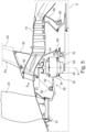
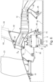
- Fig. 4 a schematic view of the front section of geared turbofan engine 10 is shown. The view axially extends from the propulsive fan 23 in the front to the low-pressure compressor 14 towards the rear.
- the drive train comprises an input shaft device 50 (e.g. comprising the shaft 26 shown in Fig. 1 ), here driven by the not shown low-pressure turbine 19.
- the input shaft device 50 is connected to the sun gear 28 of the epicyclical gearbox device 30.
- the input shaft device 50 is essentially a hollow tube device providing good torsional stiffness properties.
- the output of the gearbox device 30 takes place via the planet carrier 34 which is connected with an output shaft device 60 which has a portion acting as a fan shaft 61. That portion is rigidly connected with the propulsive fan 23.
- the output shaft 60 can be replaced by a direct connection of the fan disk 61 to the carrier 34.
- the input torque is transmitted from the input shaft device 50 to the sun gear 28 of the gearbox device 30, and to some extent to the ring gear mount.
- the planet carrier 34 transmits the output torque (at a reduced rotational speed) to the output gear device 60 and eventually to the propulsive fan 23.
- the shape of the shaft devices 50, 60 can be more complex and comprises more than one piece.
- the shafting arrangement of the embodiment shown in Fig. 4 also comprises four bearing systems e.g. for taking the mechanical loads or for locating the propulsive fan 23 and the gearbox device 30.
- the first bearing to be described is an inter-shaft bearing system 70 being positioned radially between the planet carrier 34 and the input shaft device 50.
- This inter-shaft bearing system 70 comprises one roller bearing.
- more than one roller bearing e.g. double bearings, two bearings of different design
- other bearing designs can be used. It is also possible that different bearings of the inter-shaft bearing system 70 are positioned at different locations.
- the inter-shaft bearing system 70 is, in this embodiment, axially adjacent to the gearbox device 30 on the input side.
- the axial distance between the inter-shaft carrier bearing device 70 to the gearbox device 30 can e.g. be between 0,001 and 2 times the inner radius of the inner radius of a seat element 39 for the inter-shaft bearing system. This could be in the range of 1 to 100 mm measured from the axial front side of the inter-shaft bearing device 70 to a centreline 41 of the gearbox device 30.
- the radial inner seat of the inter-shaft bearing system 70 is on seat element 39 extending axially to the rear of the gearbox device 30.
- a rear carrier bearing device 90 is positioned on the input side of the gearbox device 30.
- the fan axial load is transferred via the fan-shaft bearing system 80 (roller bearing), via the gearbox device 30 and into the input-shaft bearing 95 towards the rear.
- the support structures of the bearings can be reduced.
- the output shaft device 60 only has one bearing system, a fan shaft bearing system 80.
- the radial inner seat of that bearing system is on the fan shaft 61, being a part of the output shaft device 60.
- the radial outer seat of the fan shaft bearing system 80 is connected to a static front cone structure 81.
- a roller bearing is used in the fan shaft bearing system 80.
- more than one roller bearing e.g. double bearings, two bearings of different design
- the fan shaft bearing system 80 can have an outer diameter between 0,05 to 0,2 times the diameter of the propulsive fan 13. This range can be between 175 and 1250 mm.
- the fan shaft bearing system 80 is directly located underneath the propulsive fan 23.
- the output shaft device 60 in the embodiment shown in Fig. 4 comprises essentially a cylindrical section adjacent to the output side of the gearbox device 30 and under the propulsive fan 23 (i.e. the fan shaft section 61). In-between there is a conical section 62 linking the two cylindrical sections.
- Conical in this context means that the axial cross-section in this part of the output shaft device 60 is a straight line inclined radially inwards. In other embodiments this linking section can have different shapes than the conic shape in Fig. 4 .
- the static front cone structure 81 and the static structure 91 form together one cavity around the gearbox device 30.
- the ring gear 38 is rigidly connected to the static front cone structure 81 but alternatively, it can be connected to a different static part within the engine 10.
- the load path for force and / or torque from the driving turbine 19, i.e. the low-pressure turbine 19 to the propulsive fan 23 extends via the input shaft device 50, the through shaft 63, the gearbox device 30 and the output shaft device 60. There is no through shaft.
- the embodiment shown in Figure 5 comprises furthermore a structure comprising a plurality of struts 82, 83, 84, 85 for taking loads from the moving parts relatively close to the rotational axis 9 towards the radially outer parts of the gas turbine engine 10.
- the static front cone structure 81 transmits radial loads via a first strut 82 spanning the airflow A into the engine core 11 and the second strut 83.
- the section of the front cone structure 81 and the struts 82, 83 are aligned in a relatively straight, linear arrangement, i.e. the section of the front cone structure 81, and the struts 82, 83 are positioned within an angular field of is less than 15° measured from the base of the front cone structure 81, i.e. the fan shaft bearing system 81. With this linear arrangement, loads can effectively be transferred.
- a similar structure is located axially further to the rear.
- the static structure 91, and struts 92, 93 are aligned in an essentially vertical arrangement.
- the two structures 81, 82, 83, 91, 92, 93 described above transfer loads essentially in a radial direction.
- the channel for the core airflow A provides some stabilization in an essential axial direction resulting in a meshlike structure.
- This mesh-like structure is torsionaly stiff.
- the input shaft 50 is shown schematically as a straight shaft, i.e. essentially a hollow tube. It is possible that in an alternative embodiment the input shaft comprises flexibility means such as grooves or meandering sections to provide a defined flexibility in the shaft, though this is not in accordance with the present invention.
- the input shaft device 50 comprises a diaphragm section 51, i.e. a folded section of the input shaft device.
Landscapes
- Engineering & Computer Science (AREA)
- General Engineering & Computer Science (AREA)
- Mechanical Engineering (AREA)
- Chemical & Material Sciences (AREA)
- Combustion & Propulsion (AREA)
- Structures Of Non-Positive Displacement Pumps (AREA)
- Retarders (AREA)
Claims (15)
- Moteur à turbine à gaz, en particulier un moteur d'aéronef, comprenant :une turbine (19) reliée par l'intermédiaire d'un dispositif d'arbre d'entrée (50) à un dispositif de boîte à engrenages (30) comportant un planétaire (28), un porte-planétaire (34) comportant une pluralité de roues planétaires (32) fixées à celui-ci, et une couronne (38),le planétaire (28) est relié au dispositif d'arbre d'entrée (50),le porte-planétaire (34) ou la couronne (38) est relié(e) à une soufflante propulsive (23) par l'intermédiaire d'un dispositif d'arbre de sortie (60) du dispositif de boîte à engrenages (30), avecun dispositif de palier de porte-planétaire arrière (90) radialement entre le porte-planétaire (34) et une structure statique (91) du côté entrée du dispositif de boîte à engrenages (30),un système de palier inter-arbres (70) positionné radialement entre le dispositif d'arbre d'entrée (50) et le porte-planétaire (34) du dispositif de boîte à engrenages (30),le dispositif d'arbre d'entrée (50) possédant une rigidité élevée, caractérisé en ce que le porte-planétaire (34) comprend un élément de siège (39) s'étendant axialement vers l'arrière du dispositif de boîte à engrenages (30) fournissant un siège radial pour le dispositif de palier inter-arbres (70), le système de palier inter-arbres (70) est axialement adjacent au dispositif de boîte à engrenages (30) du côté entrée avec une distance axiale mesurée à partir de l'axe central (41) du dispositif de boîte à engrenages (30) comprise entre 0,001 et 2 fois le rayon intérieur d'un élément de siège (39) pour le système de palier inter-arbres (90).
- Turbine à gaz de la revendication 1, dans laquelle la rigidité radiale du dispositif d'arbre d'entrée est au moins 20 % de la rigidité de la structure de support du dispositif de boîte de vitesses (20), la structure de support comprenant une structure conique avant statique (81), une première entretoise (82) et une structure statique (91) et/ou une rigidité axiale supérieure ou égale à 100 % de la rigidité axiale de la structure de support du dispositif de boîte de vitesses (20), la structure de support comprenant une structure conique avant statique (81), une première entretoise (82) et une structure statique (91).
- Turbine à gaz d'au moins l'une des revendications précédentes, dans laquelle le système de palier inter-arbres (70) est situé axialement à l'intérieur ou à l'avant d'un compresseur basse pression (14) ou d'un compresseur intermédiaire.
- Turbine à gaz d'au moins l'une des revendications précédentes, dans laquelle le dispositif de palier de porte-planétaire arrière (90) comprend au moins un palier à rouleaux et/ou le système de palier inter-arbres (70) comprend au moins un palier à billes.
- Turbine à gaz d'au moins l'une des revendications précédentes, dans laquelle le système de palier inter-arbres (70) est axialement adjacent au dispositif de boîte à engrenages (30) du côté entrée avec une distance axiale mesurée à partir de l'axe central (41) du dispositif de boîte à engrenages (30) comprise entre 0,01 à 1 fois le rayon intérieur d'un élément de siège (39) pour le système de palier inter-arbres (70).
- Turbine à gaz d'au moins l'une des revendications précédentes, dans laquelle un système de palier d'arbre de soufflante (80) est disposé radialement entre un arbre de soufflante (61) faisant partie du dispositif d'arbre de sortie (60) et une structure statique, en particulier une structure conique avant statique (81), en particulier le système de palier d'arbre de soufflante (80) étant positionné axialement dans la largeur de la soufflante propulsive (23).
- Turbine à gaz de la revendication 6, dans laquelle le système de palier d'arbre de soufflante (80) a un diamètre extérieur compris entre 0,05 et 0,20 fois le diamètre de la soufflante propulsive (23), en particulier entre 0,1 et 0,15 fois le diamètre de la soufflante propulsive (23).
- Turbine à gaz d'au moins l'une des revendications précédentes, dans laquelle un système de palier d'arbre d'entrée (95) est situé radialement entre le dispositif d'arbre d'entrée (50) et une structure statique, en particulier une structure arrière statique (96), le système de palier d'arbre d'entrée (95) comprenant en particulier au moins un palier à rouleaux.
- Turbine à gaz d'au moins l'une des revendications précédentes, dans laquelle le dispositif d'arbre de sortie (60) comprend au moins une section transversale axiale de forme conique, sigmoïdale ou logarithmique.
- Turbine à gaz d'au moins l'une des revendications précédentes, dans laquelle le dispositif d'arbre de sortie (60) comprend un accouplement courbe ou cannelé.
- Turbine à gaz d'au moins l'une des revendications précédentes, dans laquelle le chemin de charge pour la force et/ou le couple de la turbine d'entraînement (19) à la soufflante propulsive (23) s'étend via le dispositif d'arbre d'entrée (50), le dispositif de boîte à engrenages (30) et le dispositif d'arbre de sortie (60).
- Turbine à gaz d'au moins l'une des revendications précédentes, dans laquelle la couronne (38) est reliée de manière rigide à la structure conique avant statique (81).
- Turbine à gaz d'au moins l'une des revendications précédentes, dans laquelle une structure statique (81, 82), comprenant des entretoises (82, 83, 92, 93) pour transférer des charges radiales, en particulier avec des pièces de la structure (81, 82, 83, 91, 92, 93) présentant une structure linéaire essentielle.
- Turbine à gaz d'au moins l'une des revendications précédentes, dans laquelle le dispositif de boîte à engrenages (30) comprend une boîte à engrenages épicycloïdale, la couronne (38) étant fixe par rapport aux autres pièces du dispositif de boîte à engrenages (30) et le dispositif d'arbre de sortie (60) étant relié au porte-planétaire (34).
- Turbine à gaz d'au moins l'une des revendications 1 à 13, dans laquelle le dispositif de boîte à engrenages (30) comprend une boîte à engrenages planétaire en étoile, le porte-planétaire (34) étant fixe par rapport aux autres pièces du dispositif de boîte à engrenages (30) et le dispositif d'arbre de sortie (60) étant relié à la couronne (38).
Applications Claiming Priority (3)
| Application Number | Priority Date | Filing Date | Title |
|---|---|---|---|
| GBGB1810526.2A GB201810526D0 (en) | 2018-06-27 | 2018-06-27 | Gas turbine |
| GBGB1810527.0A GB201810527D0 (en) | 2018-06-27 | 2018-06-27 | Gas turbine |
| GBGB1810528.8A GB201810528D0 (en) | 2018-06-27 | 2018-06-27 | Gas turbine |
Publications (2)
| Publication Number | Publication Date |
|---|---|
| EP3587774A1 EP3587774A1 (fr) | 2020-01-01 |
| EP3587774B1 true EP3587774B1 (fr) | 2025-05-07 |
Family
ID=67003308
Family Applications (3)
| Application Number | Title | Priority Date | Filing Date |
|---|---|---|---|
| EP19182048.9A Withdrawn EP3587772A1 (fr) | 2018-06-27 | 2019-06-24 | Turbine à gaz |
| EP19182049.7A Not-in-force EP3587773B1 (fr) | 2018-06-27 | 2019-06-24 | Turbine à gaz |
| EP19182050.5A Active EP3587774B1 (fr) | 2018-06-27 | 2019-06-24 | Turbine à gaz |
Family Applications Before (2)
| Application Number | Title | Priority Date | Filing Date |
|---|---|---|---|
| EP19182048.9A Withdrawn EP3587772A1 (fr) | 2018-06-27 | 2019-06-24 | Turbine à gaz |
| EP19182049.7A Not-in-force EP3587773B1 (fr) | 2018-06-27 | 2019-06-24 | Turbine à gaz |
Country Status (3)
| Country | Link |
|---|---|
| US (4) | US10914240B2 (fr) |
| EP (3) | EP3587772A1 (fr) |
| CN (3) | CN110645096A (fr) |
Families Citing this family (13)
| Publication number | Priority date | Publication date | Assignee | Title |
|---|---|---|---|---|
| US11346393B2 (en) * | 2019-05-30 | 2022-05-31 | Pratt & Whitney Canada Corp. | No pin compliant journal bearing shaft for one part carrier |
| EP3875805A1 (fr) * | 2020-03-06 | 2021-09-08 | Flender GmbH | Porte satellites, engrenage épicycloïdal, chaine cinématique et éolienne |
| US11352979B2 (en) * | 2020-04-24 | 2022-06-07 | Raytheon Technologies Corporation | Housing less front bearing compartment for gas turbine engine |
| CN112179665B (zh) * | 2020-09-18 | 2022-08-23 | 中国航发四川燃气涡轮研究院 | 一种低压涡轮性能试验入口滞止压力的获取方法 |
| FR3134867B1 (fr) * | 2022-04-22 | 2024-05-17 | Safran Trans Systems | Reducteur mecanique de turbomachine d’aeronef |
| US12281618B2 (en) | 2022-04-25 | 2025-04-22 | General Electric Company | Mounting assembly for a gearbox assembly |
| US12385443B2 (en) | 2022-04-25 | 2025-08-12 | General Electric Company | Mounting assembly for a gearbox assembly |
| US12449030B2 (en) | 2022-04-25 | 2025-10-21 | General Electric Company | Mounting assembly for a gearbox assembly |
| CN116988876A (zh) * | 2022-04-25 | 2023-11-03 | 通用电气公司 | 齿轮箱组件的安装组件 |
| US11852080B1 (en) * | 2022-08-05 | 2023-12-26 | General Electric Company | Gearbox assembly |
| FR3145776A1 (fr) * | 2023-02-15 | 2024-08-16 | Safran Aircraft Engines | Optimisation du comportement de la soufflante dans un système propulsif aéronautique |
| FR3145777A1 (fr) * | 2023-02-15 | 2024-08-16 | Safran Aircraft Engines | Optimisation du comportement de la soufflante dans un système propulsif aéronautique |
| FR3150840B1 (fr) * | 2023-07-03 | 2025-10-31 | Safran Aircraft Engines | Reducteur comportant un palier de guidage du solaire |
Family Cites Families (49)
| Publication number | Priority date | Publication date | Assignee | Title |
|---|---|---|---|---|
| US4916894A (en) * | 1989-01-03 | 1990-04-17 | General Electric Company | High bypass turbofan engine having a partially geared fan drive turbine |
| US4969325A (en) | 1989-01-03 | 1990-11-13 | General Electric Company | Turbofan engine having a counterrotating partially geared fan drive turbine |
| US5622473A (en) | 1995-11-17 | 1997-04-22 | General Electric Company | Variable stator vane assembly |
| US6223616B1 (en) | 1999-12-22 | 2001-05-01 | United Technologies Corporation | Star gear system with lubrication circuit and lubrication method therefor |
| FR2817912B1 (fr) | 2000-12-07 | 2003-01-17 | Hispano Suiza Sa | Reducteur reprenant les efforts axiaux generes par la soufflante d'un turboreacteur |
| FR2866074B1 (fr) * | 2004-02-11 | 2006-04-28 | Snecma Moteurs | Architecture d'un turboreacteur ayant une double soufflante a l'avant |
| US7490460B2 (en) * | 2005-10-19 | 2009-02-17 | General Electric Company | Gas turbine engine assembly and methods of assembling same |
| US7603844B2 (en) * | 2005-10-19 | 2009-10-20 | General Electric Company | Gas turbine engine assembly and methods of assembling same |
| US7694505B2 (en) | 2006-07-31 | 2010-04-13 | General Electric Company | Gas turbine engine assembly and method of assembling same |
| FR2942273B1 (fr) | 2009-02-18 | 2011-06-10 | Snecma | Moteur double flux a roues de turbine contrarotatives |
| FR2943035B1 (fr) * | 2009-03-11 | 2012-09-28 | Snecma | Dispositif d'entrainement d'une paire d'helices contrarotives par un train epycycloidal |
| US8511987B2 (en) * | 2009-11-20 | 2013-08-20 | United Technologies Corporation | Engine bearing support |
| US8672801B2 (en) * | 2009-11-30 | 2014-03-18 | United Technologies Corporation | Mounting system for a planetary gear train in a gas turbine engine |
| US8517672B2 (en) * | 2010-02-23 | 2013-08-27 | General Electric Company | Epicyclic gearbox |
| EP3456940B8 (fr) * | 2011-12-30 | 2020-11-04 | Raytheon Technologies Corporation | Lubrification de moteur de turbine à gaz |
| US8484942B1 (en) * | 2012-05-30 | 2013-07-16 | United Technologies Corporation | Planetary gear system arrangement with auxiliary oil system |
| US8572943B1 (en) * | 2012-05-31 | 2013-11-05 | United Technologies Corporation | Fundamental gear system architecture |
| US9926850B2 (en) * | 2013-02-11 | 2018-03-27 | United Technologies Corporation | Compound star gear system with rolling element bearings |
| US10113481B2 (en) * | 2013-03-15 | 2018-10-30 | United Technologies Corporation | Turbofan engine bearing and gearbox arrangement |
| US10094278B2 (en) * | 2013-06-03 | 2018-10-09 | United Technologies Corporation | Turbofan engine bearing and gearbox arrangement |
| FR3009594B1 (fr) | 2013-08-08 | 2016-12-09 | Snecma | Reducteur a train epicycloidal avec canalisations de transfert de fluide, et turbomachine a helice(s) pour aeronef avec un tel reducteur |
| US20150300264A1 (en) * | 2013-09-30 | 2015-10-22 | United Technologies Corporation | Geared turbofan architecture for regional jet aircraft |
| US8869504B1 (en) * | 2013-11-22 | 2014-10-28 | United Technologies Corporation | Geared turbofan engine gearbox arrangement |
| FR3016189B1 (fr) * | 2014-01-07 | 2018-09-28 | Safran Aircraft Engines | Dispositif de reduction epicycloidal pour l'entrainement en rotation des ensembles de pales d'une turbomachine a reducteur |
| FR3017164B1 (fr) | 2014-02-03 | 2016-02-05 | Snecma | Turbomachine a doublet d'helices pour aeronef |
| US10280843B2 (en) * | 2014-03-07 | 2019-05-07 | United Technologies Corporation | Geared turbofan with integral front support and carrier |
| FR3021296B1 (fr) | 2014-05-21 | 2017-12-22 | Snecma | Ensemble de propulsion a doublet d'helices pour aeronef |
| US9695710B2 (en) | 2014-09-08 | 2017-07-04 | United Technologies Corporation | Oil transfer bearing |
| GB201417505D0 (en) * | 2014-10-03 | 2014-11-19 | Rolls Royce Deutschland | A gas turbine architecture |
| GB201417504D0 (en) * | 2014-10-03 | 2014-11-19 | Rolls Royce Deutschland | A gas turbine architecture |
| DE102014117841A1 (de) * | 2014-12-04 | 2016-06-09 | Rolls-Royce Deutschland Ltd & Co Kg | Vorrichtung mit einem drehfesten ersten Bauteil und einem zumindest bereichsweise mit dem ersten Bauteil drehbar verbundenen zweiten Bauteil |
| DE102014117840A1 (de) * | 2014-12-04 | 2016-06-09 | Rolls-Royce Deutschland Ltd & Co Kg | Vorrichtung mit einem drehfesten ersten Bauteil und einem zumindest bereichsweise mit dem ersten Bauteil drehbar verbundenen zweiten Bauteil |
| GB201510050D0 (en) | 2015-06-10 | 2015-07-22 | Rolls Royce Plc | A geared gas turbine engine |
| US10119465B2 (en) * | 2015-06-23 | 2018-11-06 | United Technologies Corporation | Geared turbofan with independent flexible ring gears and oil collectors |
| US10495004B2 (en) * | 2015-09-17 | 2019-12-03 | General Electric Company | Multi-directional gearbox deflection limiter for a gas turbine engine |
| GB201516571D0 (en) * | 2015-09-18 | 2015-11-04 | Rolls Royce Plc | A Coupling for a Geared Turbo Fan |
| GB201516570D0 (en) | 2015-09-18 | 2015-11-04 | Rolls Royce Plc | A Shafting Arrangement |
| US20170089218A1 (en) * | 2015-09-25 | 2017-03-30 | General Electric Company | Double row cylindrical roller bearing with high length to diameter ratio rollers |
| US10267365B2 (en) * | 2015-12-11 | 2019-04-23 | General Electric Company | Power gearbox pin arrangement |
| GB201611605D0 (en) | 2016-07-04 | 2016-08-17 | Rolls-Royce Ltd | A Gas Turbine Engine |
| GB201611893D0 (en) | 2016-07-08 | 2016-08-24 | Rolls Royce Plc | A geared gas turbine engine and a gearbox |
| GB201612099D0 (en) | 2016-07-12 | 2016-08-24 | Rolls Royce Deutschland Ltd & Co Kg | A geared gas turbine engine |
| EP3296552B1 (fr) * | 2016-09-20 | 2019-06-05 | Rolls-Royce Deutschland Ltd & Co KG | Moteur à turbine à gaz doté d'un système de réacteur à réducteur |
| US10746188B2 (en) | 2017-03-14 | 2020-08-18 | Pratt & Whitney Canada Corp. | Inter-shaft bearing connected to a compressor boost system |
| GB201720391D0 (en) | 2017-12-07 | 2018-01-24 | Rolls Royce Plc | A gas turbine engine |
| GB201802694D0 (en) * | 2018-02-20 | 2018-04-04 | Rolls Royce Plc | Gas turbing engine fan mounting system |
| GB201805764D0 (en) * | 2018-04-06 | 2018-05-23 | Rolls Royce Plc | A casing |
| EP3587768A1 (fr) * | 2018-06-27 | 2020-01-01 | Rolls-Royce Deutschland Ltd & Co KG | Turbine à gaz |
| EP3587764A1 (fr) * | 2018-06-27 | 2020-01-01 | Rolls-Royce Deutschland Ltd & Co KG | Turbine à gaz |
-
2019
- 2019-06-24 EP EP19182048.9A patent/EP3587772A1/fr not_active Withdrawn
- 2019-06-24 EP EP19182049.7A patent/EP3587773B1/fr not_active Not-in-force
- 2019-06-24 EP EP19182050.5A patent/EP3587774B1/fr active Active
- 2019-06-25 US US16/451,677 patent/US10914240B2/en active Active
- 2019-06-25 US US16/451,606 patent/US11187157B2/en active Active
- 2019-06-25 US US16/451,543 patent/US10920672B2/en active Active
- 2019-06-27 CN CN201910568647.7A patent/CN110645096A/zh active Pending
- 2019-06-27 CN CN201910568646.2A patent/CN110645095B/zh active Active
- 2019-06-27 CN CN201910568607.2A patent/CN110645094A/zh active Pending
-
2021
- 2021-01-13 US US17/147,762 patent/US11454174B2/en active Active
Also Published As
| Publication number | Publication date |
|---|---|
| EP3587773B1 (fr) | 2022-06-08 |
| US10914240B2 (en) | 2021-02-09 |
| EP3587773A1 (fr) | 2020-01-01 |
| EP3587774A1 (fr) | 2020-01-01 |
| US20200003127A1 (en) | 2020-01-02 |
| CN110645094A (zh) | 2020-01-03 |
| CN110645096A (zh) | 2020-01-03 |
| US20210156313A1 (en) | 2021-05-27 |
| EP3587772A1 (fr) | 2020-01-01 |
| US11454174B2 (en) | 2022-09-27 |
| US20200003128A1 (en) | 2020-01-02 |
| US20200003069A1 (en) | 2020-01-02 |
| US10920672B2 (en) | 2021-02-16 |
| CN110645095A (zh) | 2020-01-03 |
| US11187157B2 (en) | 2021-11-30 |
| CN110645095B (zh) | 2024-03-01 |
Similar Documents
| Publication | Publication Date | Title |
|---|---|---|
| US11454174B2 (en) | Gas turbine | |
| US20190309681A1 (en) | Gas turbine engine and turbine arrangement | |
| US20200003122A1 (en) | Gas turbine engine | |
| EP3611398B1 (fr) | Système de palier de stabilisation pour moteurs à double flux à engrenage | |
| US20200018178A1 (en) | Gas turbine engine outlet guide vanes | |
| US20200240293A1 (en) | Component for fastening arrangement, fastening arrangement and gas turbine engine comprising fastening arrangement | |
| US20190249720A1 (en) | Driveshaft | |
| US11131209B2 (en) | Gas turbine | |
| US11879397B2 (en) | Gas turbine engine with staggered epicyclic gearbox | |
| US20220178265A1 (en) | Fluid flow guiding device and a gas turbine engine | |
| US20200003129A1 (en) | Gas turbine | |
| US20210270147A1 (en) | Torque limiting device in a connection between a gearbox and a stationary structure in a gas turbine engine and a gas turbine engine | |
| US11230945B2 (en) | Gas turbine engine with intermediate case bearing arrangement | |
| EP3546367B1 (fr) | Agencement de montage de moteur à double flux à engrenage | |
| EP3594476B1 (fr) | Agencement de montage de moteur à turbine à gaz à turbosoufflante à engrenage | |
| US11306663B2 (en) | Gas turbine engine | |
| US20190360359A1 (en) | Gas turbine engine | |
| US20190316490A1 (en) | Joint |
Legal Events
| Date | Code | Title | Description |
|---|---|---|---|
| PUAI | Public reference made under article 153(3) epc to a published international application that has entered the european phase |
Free format text: ORIGINAL CODE: 0009012 |
|
| STAA | Information on the status of an ep patent application or granted ep patent |
Free format text: STATUS: THE APPLICATION HAS BEEN PUBLISHED |
|
| AK | Designated contracting states |
Kind code of ref document: A1 Designated state(s): AL AT BE BG CH CY CZ DE DK EE ES FI FR GB GR HR HU IE IS IT LI LT LU LV MC MK MT NL NO PL PT RO RS SE SI SK SM TR |
|
| AX | Request for extension of the european patent |
Extension state: BA ME |
|
| STAA | Information on the status of an ep patent application or granted ep patent |
Free format text: STATUS: REQUEST FOR EXAMINATION WAS MADE |
|
| RAP1 | Party data changed (applicant data changed or rights of an application transferred) |
Owner name: ROLLS-ROYCE PLC |
|
| 17P | Request for examination filed |
Effective date: 20200207 |
|
| RBV | Designated contracting states (corrected) |
Designated state(s): AL AT BE BG CH CY CZ DE DK EE ES FI FR GB GR HR HU IE IS IT LI LT LU LV MC MK MT NL NO PL PT RO RS SE SI SK SM TR |
|
| STAA | Information on the status of an ep patent application or granted ep patent |
Free format text: STATUS: EXAMINATION IS IN PROGRESS |
|
| 17Q | First examination report despatched |
Effective date: 20220315 |
|
| GRAP | Despatch of communication of intention to grant a patent |
Free format text: ORIGINAL CODE: EPIDOSNIGR1 |
|
| STAA | Information on the status of an ep patent application or granted ep patent |
Free format text: STATUS: GRANT OF PATENT IS INTENDED |
|
| GRAS | Grant fee paid |
Free format text: ORIGINAL CODE: EPIDOSNIGR3 |
|
| RIC1 | Information provided on ipc code assigned before grant |
Ipc: F02K 3/06 20060101ALI20250221BHEP Ipc: F02C 7/36 20060101AFI20250221BHEP |
|
| GRAA | (expected) grant |
Free format text: ORIGINAL CODE: 0009210 |
|
| STAA | Information on the status of an ep patent application or granted ep patent |
Free format text: STATUS: THE PATENT HAS BEEN GRANTED |
|
| INTG | Intention to grant announced |
Effective date: 20250313 |
|
| P01 | Opt-out of the competence of the unified patent court (upc) registered |
Free format text: CASE NUMBER: APP_13875/2025 Effective date: 20250320 |
|
| AK | Designated contracting states |
Kind code of ref document: B1 Designated state(s): AL AT BE BG CH CY CZ DE DK EE ES FI FR GB GR HR HU IE IS IT LI LT LU LV MC MK MT NL NO PL PT RO RS SE SI SK SM TR |
|
| REG | Reference to a national code |
Ref country code: GB Ref legal event code: FG4D |
|
| REG | Reference to a national code |
Ref country code: CH Ref legal event code: EP |
|
| REG | Reference to a national code |
Ref country code: DE Ref legal event code: R096 Ref document number: 602019069553 Country of ref document: DE |
|
| REG | Reference to a national code |
Ref country code: IE Ref legal event code: FG4D |
|
| PGFP | Annual fee paid to national office [announced via postgrant information from national office to epo] |
Ref country code: DE Payment date: 20250626 Year of fee payment: 7 |
|
| PGFP | Annual fee paid to national office [announced via postgrant information from national office to epo] |
Ref country code: GB Payment date: 20250617 Year of fee payment: 7 |
|
| PGFP | Annual fee paid to national office [announced via postgrant information from national office to epo] |
Ref country code: FR Payment date: 20250624 Year of fee payment: 7 |
|
| REG | Reference to a national code |
Ref country code: NL Ref legal event code: MP Effective date: 20250507 |
|
| PG25 | Lapsed in a contracting state [announced via postgrant information from national office to epo] |
Ref country code: FI Free format text: LAPSE BECAUSE OF FAILURE TO SUBMIT A TRANSLATION OF THE DESCRIPTION OR TO PAY THE FEE WITHIN THE PRESCRIBED TIME-LIMIT Effective date: 20250507 Ref country code: ES Free format text: LAPSE BECAUSE OF FAILURE TO SUBMIT A TRANSLATION OF THE DESCRIPTION OR TO PAY THE FEE WITHIN THE PRESCRIBED TIME-LIMIT Effective date: 20250507 Ref country code: PT Free format text: LAPSE BECAUSE OF FAILURE TO SUBMIT A TRANSLATION OF THE DESCRIPTION OR TO PAY THE FEE WITHIN THE PRESCRIBED TIME-LIMIT Effective date: 20250908 |
|
| REG | Reference to a national code |
Ref country code: LT Ref legal event code: MG9D |
|
| PG25 | Lapsed in a contracting state [announced via postgrant information from national office to epo] |
Ref country code: NO Free format text: LAPSE BECAUSE OF FAILURE TO SUBMIT A TRANSLATION OF THE DESCRIPTION OR TO PAY THE FEE WITHIN THE PRESCRIBED TIME-LIMIT Effective date: 20250807 Ref country code: GR Free format text: LAPSE BECAUSE OF FAILURE TO SUBMIT A TRANSLATION OF THE DESCRIPTION OR TO PAY THE FEE WITHIN THE PRESCRIBED TIME-LIMIT Effective date: 20250808 |
|
| PG25 | Lapsed in a contracting state [announced via postgrant information from national office to epo] |
Ref country code: PL Free format text: LAPSE BECAUSE OF FAILURE TO SUBMIT A TRANSLATION OF THE DESCRIPTION OR TO PAY THE FEE WITHIN THE PRESCRIBED TIME-LIMIT Effective date: 20250507 Ref country code: NL Free format text: LAPSE BECAUSE OF FAILURE TO SUBMIT A TRANSLATION OF THE DESCRIPTION OR TO PAY THE FEE WITHIN THE PRESCRIBED TIME-LIMIT Effective date: 20250507 |
|
| REG | Reference to a national code |
Ref country code: AT Ref legal event code: MK05 Ref document number: 1792688 Country of ref document: AT Kind code of ref document: T Effective date: 20250507 |
|
| PG25 | Lapsed in a contracting state [announced via postgrant information from national office to epo] |
Ref country code: BG Free format text: LAPSE BECAUSE OF FAILURE TO SUBMIT A TRANSLATION OF THE DESCRIPTION OR TO PAY THE FEE WITHIN THE PRESCRIBED TIME-LIMIT Effective date: 20250507 |
|
| PG25 | Lapsed in a contracting state [announced via postgrant information from national office to epo] |
Ref country code: HR Free format text: LAPSE BECAUSE OF FAILURE TO SUBMIT A TRANSLATION OF THE DESCRIPTION OR TO PAY THE FEE WITHIN THE PRESCRIBED TIME-LIMIT Effective date: 20250507 |
|
| PG25 | Lapsed in a contracting state [announced via postgrant information from national office to epo] |
Ref country code: AT Free format text: LAPSE BECAUSE OF FAILURE TO SUBMIT A TRANSLATION OF THE DESCRIPTION OR TO PAY THE FEE WITHIN THE PRESCRIBED TIME-LIMIT Effective date: 20250507 |
|
| PG25 | Lapsed in a contracting state [announced via postgrant information from national office to epo] |
Ref country code: RS Free format text: LAPSE BECAUSE OF FAILURE TO SUBMIT A TRANSLATION OF THE DESCRIPTION OR TO PAY THE FEE WITHIN THE PRESCRIBED TIME-LIMIT Effective date: 20250807 |
|
| PG25 | Lapsed in a contracting state [announced via postgrant information from national office to epo] |
Ref country code: IS Free format text: LAPSE BECAUSE OF FAILURE TO SUBMIT A TRANSLATION OF THE DESCRIPTION OR TO PAY THE FEE WITHIN THE PRESCRIBED TIME-LIMIT Effective date: 20250907 |
|
| PG25 | Lapsed in a contracting state [announced via postgrant information from national office to epo] |
Ref country code: LV Free format text: LAPSE BECAUSE OF FAILURE TO SUBMIT A TRANSLATION OF THE DESCRIPTION OR TO PAY THE FEE WITHIN THE PRESCRIBED TIME-LIMIT Effective date: 20250507 |
|
| PG25 | Lapsed in a contracting state [announced via postgrant information from national office to epo] |
Ref country code: DK Free format text: LAPSE BECAUSE OF FAILURE TO SUBMIT A TRANSLATION OF THE DESCRIPTION OR TO PAY THE FEE WITHIN THE PRESCRIBED TIME-LIMIT Effective date: 20250507 Ref country code: SM Free format text: LAPSE BECAUSE OF FAILURE TO SUBMIT A TRANSLATION OF THE DESCRIPTION OR TO PAY THE FEE WITHIN THE PRESCRIBED TIME-LIMIT Effective date: 20250507 |
|
| PG25 | Lapsed in a contracting state [announced via postgrant information from national office to epo] |
Ref country code: CZ Free format text: LAPSE BECAUSE OF FAILURE TO SUBMIT A TRANSLATION OF THE DESCRIPTION OR TO PAY THE FEE WITHIN THE PRESCRIBED TIME-LIMIT Effective date: 20250507 |
|
| PG25 | Lapsed in a contracting state [announced via postgrant information from national office to epo] |
Ref country code: EE Free format text: LAPSE BECAUSE OF FAILURE TO SUBMIT A TRANSLATION OF THE DESCRIPTION OR TO PAY THE FEE WITHIN THE PRESCRIBED TIME-LIMIT Effective date: 20250507 |
|
| PG25 | Lapsed in a contracting state [announced via postgrant information from national office to epo] |
Ref country code: RO Free format text: LAPSE BECAUSE OF FAILURE TO SUBMIT A TRANSLATION OF THE DESCRIPTION OR TO PAY THE FEE WITHIN THE PRESCRIBED TIME-LIMIT Effective date: 20250507 Ref country code: SK Free format text: LAPSE BECAUSE OF FAILURE TO SUBMIT A TRANSLATION OF THE DESCRIPTION OR TO PAY THE FEE WITHIN THE PRESCRIBED TIME-LIMIT Effective date: 20250507 |
|
| REG | Reference to a national code |
Ref country code: CH Ref legal event code: H13 Free format text: ST27 STATUS EVENT CODE: U-0-0-H10-H13 (AS PROVIDED BY THE NATIONAL OFFICE) Effective date: 20260127 |
|
| PG25 | Lapsed in a contracting state [announced via postgrant information from national office to epo] |
Ref country code: IT Free format text: LAPSE BECAUSE OF FAILURE TO SUBMIT A TRANSLATION OF THE DESCRIPTION OR TO PAY THE FEE WITHIN THE PRESCRIBED TIME-LIMIT Effective date: 20250507 |
|
| REG | Reference to a national code |
Ref country code: DE Ref legal event code: R097 Ref document number: 602019069553 Country of ref document: DE |
|
| PG25 | Lapsed in a contracting state [announced via postgrant information from national office to epo] |
Ref country code: LU Free format text: LAPSE BECAUSE OF NON-PAYMENT OF DUE FEES Effective date: 20250624 |
|
| PG25 | Lapsed in a contracting state [announced via postgrant information from national office to epo] |
Ref country code: MC Free format text: LAPSE BECAUSE OF FAILURE TO SUBMIT A TRANSLATION OF THE DESCRIPTION OR TO PAY THE FEE WITHIN THE PRESCRIBED TIME-LIMIT Effective date: 20250507 |
|
| REG | Reference to a national code |
Ref country code: BE Ref legal event code: MM Effective date: 20250630 |
|
| PLBE | No opposition filed within time limit |
Free format text: ORIGINAL CODE: 0009261 |
|
| STAA | Information on the status of an ep patent application or granted ep patent |
Free format text: STATUS: NO OPPOSITION FILED WITHIN TIME LIMIT |
|
| REG | Reference to a national code |
Ref country code: CH Ref legal event code: L10 Free format text: ST27 STATUS EVENT CODE: U-0-0-L10-L00 (AS PROVIDED BY THE NATIONAL OFFICE) Effective date: 20260318 |
|
| PG25 | Lapsed in a contracting state [announced via postgrant information from national office to epo] |
Ref country code: IE Free format text: LAPSE BECAUSE OF NON-PAYMENT OF DUE FEES Effective date: 20250624 |
|
| 26N | No opposition filed |
Effective date: 20260210 |
|
| PG25 | Lapsed in a contracting state [announced via postgrant information from national office to epo] |
Ref country code: BE Free format text: LAPSE BECAUSE OF NON-PAYMENT OF DUE FEES Effective date: 20250630 |