EP3587782A1 - Stirlingmotor - Google Patents
Stirlingmotor Download PDFInfo
- Publication number
- EP3587782A1 EP3587782A1 EP18766615.1A EP18766615A EP3587782A1 EP 3587782 A1 EP3587782 A1 EP 3587782A1 EP 18766615 A EP18766615 A EP 18766615A EP 3587782 A1 EP3587782 A1 EP 3587782A1
- Authority
- EP
- European Patent Office
- Prior art keywords
- space
- operating fluid
- crankcase
- path
- filling
- Prior art date
- Legal status (The legal status is an assumption and is not a legal conclusion. Google has not performed a legal analysis and makes no representation as to the accuracy of the status listed.)
- Withdrawn
Links
Images




Classifications
-
- F—MECHANICAL ENGINEERING; LIGHTING; HEATING; WEAPONS; BLASTING
- F02—COMBUSTION ENGINES; HOT-GAS OR COMBUSTION-PRODUCT ENGINE PLANTS
- F02G—HOT GAS OR COMBUSTION-PRODUCT POSITIVE-DISPLACEMENT ENGINE PLANTS; USE OF WASTE HEAT OF COMBUSTION ENGINES; NOT OTHERWISE PROVIDED FOR
- F02G1/00—Hot gas positive-displacement engine plants
- F02G1/04—Hot gas positive-displacement engine plants of closed-cycle type
- F02G1/043—Hot gas positive-displacement engine plants of closed-cycle type the engine being operated by expansion and contraction of a mass of working gas which is heated and cooled in one of a plurality of constantly communicating expansible chambers, e.g. Stirling cycle type engines
- F02G1/053—Component parts or details
-
- F—MECHANICAL ENGINEERING; LIGHTING; HEATING; WEAPONS; BLASTING
- F02—COMBUSTION ENGINES; HOT-GAS OR COMBUSTION-PRODUCT ENGINE PLANTS
- F02G—HOT GAS OR COMBUSTION-PRODUCT POSITIVE-DISPLACEMENT ENGINE PLANTS; USE OF WASTE HEAT OF COMBUSTION ENGINES; NOT OTHERWISE PROVIDED FOR
- F02G2253/00—Seals
-
- F—MECHANICAL ENGINEERING; LIGHTING; HEATING; WEAPONS; BLASTING
- F02—COMBUSTION ENGINES; HOT-GAS OR COMBUSTION-PRODUCT ENGINE PLANTS
- F02G—HOT GAS OR COMBUSTION-PRODUCT POSITIVE-DISPLACEMENT ENGINE PLANTS; USE OF WASTE HEAT OF COMBUSTION ENGINES; NOT OTHERWISE PROVIDED FOR
- F02G2270/00—Constructional features
- F02G2270/95—Pressurised crankcases
Definitions
- the present invention relates to a stirling engine. Specifically, the present invention relates to a stirling engine having a configuration in which a crank box accommodating a power conversion member is disposed in a crankcase.
- Patent Literature 1 discloses a stirling engine of this type.
- the stirling engine described in PTL 1 is configured such that operating fluid filling a cylinder is heated and cooled from the outside of the cylinder, and by utilizing a pressure change of the operating fluid, a piston is caused to reciprocate, and this reciprocating movement of the piston is converted to rotation movement of a crankshaft by a power conversion member and is taken out.
- a space accommodating the piston and the power conversion member (Helium chamber) is filled with operating fluid, and spaces at the sides thereof (air chambers) are filled with air.
- the Helium chamber and the air chamber are kept substantially at the same pressure in order to make a simple low-pressure seal usable as a member for sealing a gap between the Helium chamber and the air chamber.
- the filling needs to be performed little by little in a sufficiently long period with the Helium chamber and the air chamber being adjusted to substantially the same pressure in order to prevent or reduce damage of the low-pressure seal by the atmospheric pressure difference.
- Patent Literature 2 also discloses an example of the stirling engine.
- the stirling engine described in PTL 2 is configured such that a crank box accommodating a power conversion member, which is a member different from a crankcase kept under a high-pressure atmosphere, is disposed inside the crankcase.
- a wet sump lubrication method or a built-in lubrication method is employed as a method for lubricating the power conversion member as a sliding member.
- an oil seal is disposed in a gap as appropriate in order to keep the crank box in a state sealed with respect to the crankcase.
- crankcase is filled with a high-pressure gas
- some measures for preventing or reducing damage of the oil seal is needed by, for example, performing the filling in a sufficiently long period at a lower supply rate of the gas.
- the configurations of PTL 1 and PTL 2 have a room for improvement in terms of the necessity for a relatively long period in filling with operating fluid or discharging operating fluid used for the filling.
- the present invention has been made in view of the circumstances described above. It is an object of the present invention to provide a stirling engine capable of filling a space with operating fluid or discharging the operating fluid in a short period.
- a stirling engine having the following configuration.
- the stirling engine includes a crankcase, a crank box, and a path.
- a crankshaft for taking power to outside is bridged across the crankcase.
- the crank box is disposed in the crankcase and accommodates a power conversion member, and the power conversion member is configured to convert reciprocating movement of a piston to rotation movement of the crankshaft.
- the path is configured to take a balance between a pressure of a first space in the crank box and a pressure of a second space inside the crankcase and outside the crank box.
- the path preferably includes a channel through which the first space and the second space communicate with each other.
- the stirling engine preferably has the following configuration.
- the path includes a first end and a second end.
- the first end is open to the first space.
- the second end is open to the second space.
- At least a part of an intermediate portion of the path between the first end and the second end is located outside the crankcase.
- the valve can be operated by an operator from outside the crankcase so that the inside of the crankcase and the inside of the crank box can communicate with each other only when necessary.
- the stirling engine preferably has the following configuration.
- the path includes a first path and a second path.
- the first path has one end open to the first space and another end located outside the crankcase.
- the second path has one end open to the second space and another end located outside the crankcase.
- operating fluid can be supplied from each of the other end of the first path and the other end of the second path at an appropriate flow rate when necessary in consideration of the ratio between the volume of the portion filled with operating fluid by supplying the operating fluid to the first space and the volume of the portion filled with operating fluid by supplying the operating fluid to the second space, for example.
- the first and second spaces can be filled with operating fluid with a balance kept between the pressure of the first space and the pressure of the second space.
- a ratio between a channel area of the first path and a channel area of the second path is preferably set in consideration of a ratio between a volume of a portion filled with operating fluid by supplying the operating fluid to the first space and a volume of a portion filled with operating fluid by supplying the operating fluid to the second space.
- a balance can be easily kept between the pressure of the first space and the pressure of the second space so that the first and second spaces can be quickly filled with operating fluid easily.
- At least one of the first path and the second path is preferably provided with a valve or a throttle, and each of the valve and the throttle is configured to restrict a channel area of a channel in the at least one of the first path and the second path.
- operating fluid can be quickly supplied and discharged to/from the first and second spaces quickly with a substantial balance kept between the pressure of the first space and the pressure of the second space.
- each of the valve and the throttle is preferably configured to adjust the channel area of the channel.
- pressure adjustment can be flexibly performed in accordance with various situations.
- the stirling engine preferably has the following configuration. Specifically, the stirling engine further includes a pressure difference sensor and a control device.
- the pressure difference sensor detects a difference between a pressure of the first space and a pressure of the second space.
- the control device controls a state of the valve or the throttle in accordance with a detection result of the pressure difference sensor.
- Fig. 1 is a schematic view illustrating an overall configuration of the stirling engine 1 according to one embodiment of the present invention.
- the stirling engine 1 of this embodiment illustrated in Fig. 1 is a type of an external combustion engine.
- the stirling engine 1 is configured to expand and contract operating fluid filling a cylinder 2 by using heat taken from the outside to thereby cause a power piston 3 to reciprocate, and this reciprocating movement is converted to rotation movement of a crankshaft 8 so that power is taken out.
- the stirling engine 1 mainly includes a cylinder 2, the power piston 3, a displacer piston 4, a heater 5, a regenerator 6, a cooler 7, a crankshaft 8, a crankcase 9, a flywheel 10, a crank box 11, first power conversion members (power conversion member) 30, and a second power conversion member 40.
- the stirling engine 1 of this embodiment is a so-called ⁇ type stirling engine in which the power piston 3 and the displacer piston 4 are accommodated in the same cylinder 2.
- the cylinder 2 is a cylindrical member accommodating the power piston 3 and the displacer piston 4.
- the cylinder 2 is filled with operating fluid.
- operating fluid various types of fluid such as a helium gas, a hydrogen gas, and air may be used, and a helium gas having a high thermal conductivity is used in this embodiment.
- One axial end of the cylinder 2 is connected to the heater 5 above the displacer piston 4, and the other axial end of the cylinder 2 is connected to the crankcase 9.
- operating fluid changes its pressure in the cylinder 2 by heating and cooling the operating fluid.
- the displacer piston 4 is an approximately columnar member that is accommodated in the cylinder 2 to be slidable in the axial direction.
- an expansion space S1 at a relatively high temperature is formed at a side closer to a portion where the cylinder 2 and the heater 5 are connected than the displacer piston 4 (i.e., above the displacer piston 4 in the drawing).
- a compression space S2 at a relatively low temperature is formed in the cylinder 2 at a side closer to the crankcase 9 than the displacer piston 4 (i.e., below the displacer piston 4 in the drawing).
- the displacer piston 4 changes a volume ratio between the high-temperature expansion space S1 and the low-temperature compression space S2.
- the power piston 3 is a short columnar member that is housed in the cylinder 2 to be slidable in the axial direction.
- the power piston 3 is located closer to the crankcase 9 than the displacer piston 4.
- the compression space S2 is disposed between the displacer piston 4 and the power piston 3.
- the power piston 3 is displaced in the axial direction by a pressure change of operating fluid between the expansion space S1 and the compression space S2 (a high-temperature region and a low-temperature region), that is, a force caused by a pressure difference between an upper portion and a lower portion of the power piston 3.
- the heater 5, the regenerator 6, and the cooler 7 are arranged in this order from the connection side between the cylinder 2 and the heater 5 toward the portion where the crankcase 9 is disposed, immediately outside the cylinder 2.
- Operating fluid is allowed to flow from the expansion space S1 into the compression space S2 through the heater 5, the regenerator 6, and the cooler 7 in this order.
- the operating fluid is also allowed to flow from the compression space S2 into the expansion space S1 through the cooler 7, the regenerator 6, and the heater 5 in this order.
- the heater 5 is a heat exchanger for heating operating fluid.
- the heater 5 may have various known configurations, and in this embodiment, has a configuration in which operating fluid flows in a large number of fine tubes arranged to obtain a large heat-transfer area.
- a heating medium is, for example, an exhaust gas generated by a power plant or other places, and flows outside the fine tubes of the heater 5. In this manner, the temperature of the operating fluid is increased (the operating fluid is heated) by receiving heat from the heating medium.
- the cooler 7 is a heat exchanger for cooling operating fluid.
- the cooler 7 may have various known configurations, and in this embodiment, employs a configuration including a large number of fine tubes, in a manner similar to the heater 5.
- a cooling medium cooled by some method flows outside the fine tubes of the cooler 7 so that heat is taken by the cooling medium from operating fluid flowing in the fine tubes and the temperature is reduced (cooling).
- the regenerator 6 is a heat exchanger for thermal storage.
- the regenerator 6 may have various known configurations, and in this embodiment, has a configuration in which metal meshes are stacked.
- the regenerator 6 takes heat from the operating fluid and stores the heat.
- the regenerator 6 transfers the heat thus stored to the operating fluid.
- the crankshaft 8 is configured to convert power generated in the cylinder 2 (specifically, power caused by the reciprocating movement of the power piston 3) to rotation movement.
- the crankshaft 8 is rotatably supported by the crankcase 9.
- One end of the crankshaft 8 projects to the outside of the crankcase 9, and an electric generator 29 is attached to this end. This electric generator 29 converts the rotation movement of the crankshaft 8 to electric power.
- the crankcase 9 is a case across which the crankshaft 8 is bridged, and accommodates the flywheel 10 and the crank box 11 therein.
- the cylinder 2 and the crankcase 9 communicate with each other through an unillustrated hole.
- the crankcase 9 is filled with operating fluid.
- the flywheel 10 is a disk-shaped member, and is disposed in a region inside the crankcase 9 and outside the crank box 11 while being penetrated by the crankshaft 8.
- the flywheel 10 serves as a flywheel for smoothly rotating the crankshaft 8 with a reduced variation in rotation speed while maintaining a momentum of rotation of the crankshaft 8.
- the crank box 11 accommodates the first power conversion members 30 for converting reciprocating movement of the power piston 3 to rotation movement of the crankshaft 8.
- the crank box 11 accommodates the second power conversion member 40 for converting rotation movement of the crankshaft 8 to reciprocating movement of the displacer piston 4.
- These power conversion members 30 and 40 are sliding members (more strictly, include sliding members), and thus, need lubrication.
- the stirling engine 1 of this embodiment employs a wet sump lubrication method that lubricates the power conversion members 30 and 40 with lubricating oil stored in the crank box 11.
- this lubricating oil might adversely affect performance of the heat exchangers 5, 6, and 7, for example.
- lubricating oil adheres to the metal meshes of the regenerator 6 described above or the like, for example, the regenerator 6 might be blocked and a flow of operating fluid might be hindered.
- lubricating oil is stored only in the crank box 11 accommodating the power conversion members 30 and 40 that need lubrication, and leakage of lubricating oil to a region in the crankcase 9 located outside the crank box 11 (i.e., a region inside the crankcase 9 and outside the crank box 11) is prevented or reduced.
- the crankcase 9 has a double structure and lubricating oil is enclosed in the crank box 11 corresponding to the innermost space of the double structure to thereby prevent or reduce intrusion of lubricating oil in the cylinder 2.
- Oil seals 21, 22, and 23 are provided to keep the inside of the crank box 11 sealed (closed) with respect to the outer space.
- the oil seals 21, 22, and 23 are sealing members for keeping the inner space of the crank box 11 in a substantially hermetic state with respect to a space inside the crankcase 9 and outside the crank box 11.
- crankshaft 8 penetrates the crank box 11.
- a portion in which the crankshaft 8 penetrates the crank box 11 is provided with the oil seal 21 for filling a gap between the outer peripheral surface of the crankshaft 8 and a through hole formed in the crank box 11.
- This structure prevents or reduces leakage of lubricating oil in the crank box 11 through the gap between the outer peripheral surface of the crankshaft 8 and the through hole in the crank box 11.
- the first power conversion members 30 are configured to convert reciprocating movement of the power piston 3 to rotation movement of the crankshaft 8, and provided as a pair to sandwich the second power conversion member 40 described later.
- various mechanisms such as a crosshead mechanism, a rhombic mechanism, and a Scotch yoke mechanism can be used as a mechanism for converting reciprocating movement to rotation movement.
- a Scotch yoke mechanism having a reduced size and a relatively simple structure is employed as the first power conversion members 30.
- each of the first power conversion members 30 of this embodiment includes, for example, a power piston yoke 31, guide shafts 32, a first eccentric crankpin (not shown), and a rod 34.
- the power piston yoke 31 is a plate-shape member capable of sliding (reciprocating).
- the power piston yoke 31 has a pair or through holes penetrating the power piston yoke 31.
- the pair or through holes extends in parallel with the axial direction of the cylinder 2.
- the power piston yoke 31 has a guide groove penetrating the plate surface thereof. As will be described later, this guide groove accommodates the first eccentric crankpin.
- the guide shafts 32 are axial members extending in parallel with the axial direction of the cylinder 2, and each of the guide shafts 32 has one end fixed to the crank box 11 (see Fig. 2 ).
- the guide shafts 32 are provided as a pair sandwiching the crankshaft 8.
- the guide shafts 32 are inserted in the through holes of the power piston yoke 31. Accordingly, the guide shafts 32 slidably support the power piston yoke 31.
- a linear motion bearing such as a rotary bushing is disposed in a sliding portion between the through holes of the power piston yoke 31 and the guide shafts 32.
- the first eccentric crankpin is a crankpin that is eccentrically attached to the crankshaft 8.
- the first eccentric crankpin is fixed to the crankshaft 8 or integrally formed with the crankshaft 8, while penetrating the crankshaft 8.
- the first eccentric crankpin is accommodated in the guide groove of the power piston yoke 31 such that the first eccentric crankpin can move while rolling in the guide groove.
- a rotation bearing such as a rolling bearing is provided in a sliding portion between the guide groove of the power piston yoke 31 and the first eccentric crankpin.
- the rod 34 is configured to link reciprocating movement of the power piston yoke 31 and reciprocating movement of the power piston 3 to each other.
- the rod 34 has a long axial shape, and has one end connected to the power piston 3 and the other end connected to the power piston yoke 31.
- a portion in which the rod 34 penetrates the crank box 11 is provided with the oil seal 22 for filling a gap between the outer peripheral surface of the rod 34 and a through hole formed in the crank box 11. Accordingly, leakage of lubricating oil in the crank box 11 through the gap between the outer peripheral surface of the rod 34 and the through hole in the crank box 11 is prevented or reduced.
- the power piston yoke 31 coupled to the power piston 3 through the rod 34 slides along the guide shafts 32, and accordingly, the first eccentric crankpin moves in the guide groove while rolling. Accordingly, the crankshaft 8 is displaced by rotation. In this manner, reciprocating movement of the power piston 3 is converted to rotation movement of the crankshaft 8, and the rotation movement is transferred to the electric generator 29.
- the second power conversion member 40 is configured to convert rotation movement of the crankshaft 8 to reciprocating movement of the displacer piston 4.
- a Scotch yoke mechanism is employed as the second power conversion member 40, in a manner similar to the first power conversion members 30.
- the second power conversion member 40 of this embodiment includes, for example, a displacer yoke 41, a guide shaft 42, a second eccentric crankpin, and a rod 44.
- the configurations of the displacer yoke 41, the guide shaft 42, the second eccentric crankpin, and the rod 44 of the second power conversion member 40 are substantially the same as those of the power piston yoke 31, the guide shafts 32, the first eccentric crankpin, and the rod 34 of the first power conversion members 30, respectively, and thus, will not be described in detail.
- the rod 44 of the second power conversion member 40 is inserted in an unillustrated through hole formed in the power piston 3 in order to couple the displacer yoke 41 and the displacer piston 4 to each other.
- the power piston 3 is slidably provided to the rod 44, and this sliding portion is provided with an unillustrated seal mechanism for keeping hermeticity.
- a portion where the rod 44 penetrates the crank box 11 is provided with an oil seal 23 for filling a gap between the outer peripheral surface of the rod 44 and the through hole formed in the crank box 11.
- the second eccentric crankpin integrally formed with the crankshaft 8 moves in the guide groove of the displacer yoke 41 while rolling. With this movement, the displacer yoke 41 slides along the guide shaft 42. Accordingly, the displacer piston 4 coupled to the displacer yoke 41 through the rod 44 is displaced in conjunction with the displacer yoke 41. In this manner, the rotation movement of the crankshaft 8 is converted to reciprocating movement of the displacer piston 4, and in cooperation with reciprocating movement of the power piston 3, a volume ratio between the expansion space S1 and the compression space S2 varies periodically.
- the first eccentric crankpin and the second eccentric crankpin are disposed to have a predetermined phase difference (phase difference of 90° in this embodiment) such that a timing at which the power piston 3 reaches a top dead point (a highest point above the cylinder 2 in Fig. 1 ) and a timing at which the displacer piston 4 reaches the top dead point are shifted from each other.
- the displacer piston 4 With the rotation of the crankshaft 8, the displacer piston 4 reaches the bottom dead point. Thereafter, when the displacer piston 4 rises, the volume of the expansion space S1 decreases and the volume of the compression space S2 increases. Accordingly, operating fluid in the expansion space S1 passes through the heater 5, the regenerator 6, and the cooler 7 in this order, and moves into the compression space S2. In this process, the operating fluid is cooled to a relatively low temperature, and the pressure thereof decreases.
- the power piston 3 reaches the bottom dead point after the displacer piston 4, and then starts rising. Subsequently, the displacer piston 4 reaches a point near the top dead point.
- the foregoing cycle is repeated so that the pressure changes of operating fluid in the expansion space S1 and the compression space S2 are repeated.
- the power piston 3 reciprocates, and this reciprocating movement is converted to rotation movement of the crankshaft 8, and power is taken.
- the expansion space S1 and the compression space S2 are filled with operating fluid in the manner described above.
- a space in the cylinder 2 closer to the crankshaft 8 than the power piston 3 (hereinafter referred to as a space at the rear of the power piston 3), the crankcase 9, and the crank box 11 are also filled with operating fluid.
- these spaces are filled with operating fluid under high pressure (higher than the atmospheric pressure) in order to obtain power efficiently by increasing a pressure change of operating fluid.
- Fig. 7 illustrates an example of a conventional stirling engine having an operating fluid passage.
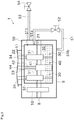
- Fig. 2 is a schematic view illustrating a partial configuration of the stirling engine 1 according to the first embodiment.
- first space S11 the space inside the crank box 11
- second space S9 the space located outside the crank box 11 and inside the crankcase 9
- the stirling engine 1 of this embodiment includes a connection route (path) 51, a valve 52, an operating fluid passage 53, and a valve 54.
- connection route 51 is a path for keeping a balance between the pressure of the first space S11 and the pressure of the second space S9.
- the connection route 51 of this embodiment is a pipe member having a circular cross section, and a channel in which operating fluid flows is formed inside the connection path 51.
- the connection route 51 includes a channel that communicates the first space S11 and the second space S9 with each other.
- connection route 51 One end (first end) 51a of the connection route 51 is connected to a side surface of the crank box 11 and is open (has an opening) to the first space S11.
- the end 51a of the connection route 51 is disposed above a liquid level of an oil sump of lubricating oil in the crank box 11.
- a specific example of the liquid level of the oil sump of lubricating oil is shown by a chain double-dashed line in the drawing.
- the other end (second end) 51b of the connection route 51 is connected to the bottom surface of the crankcase 9, and is open (has an opening) to the second space S9.
- connection route 51 between the one end 51a and the other end 51b is disposed outside the crankcase 9.
- the valve 52 is a valve capable of opening and closing a channel in the connection route 51.
- the valve 52 is disposed in the intermediate portion of the connection route 51.
- the valve 52 is disposed in a portion of the connection route 51 outside the crankcase 9.
- the valve 52 is configured to be opened and closed manually by an operator.
- the operating fluid passage 53 is a passage for distributing operating fluid in filling the first space S11 and the second space S9 with operating fluid and in discharging (releasing) the operating fluid from the first space S11 and the second space S9.
- the operating fluid passage 53 of this embodiment is a pipe member having a circular cross section, and a channel in which operating fluid flows is formed inside the operating fluid passage 53.
- One end of the operating fluid passage 53 is connected to a side surface of the crankcase 9, and is open to the second space S9.
- the other end of the operating fluid passage 53 is open to the outside of the crankcase 9.
- the valve 54 is a valve capable of opening and closing a channel in the operating fluid passage 53.
- the valve 54 is disposed in the operating fluid passage 53.
- the valve 54 is configured to be opened and closed manually by an operator.
- filling the first space S11 and the second space S9 with operating fluid is performed in the following manner. That is, before start of filling with the operating fluid, the valve 52 is opened so that the first space S11 and the second space S9 are connected to each other (communicate with each other). The space at the rear of the power piston 3 and the compression space S2 are connected to each other through a communication path (not shown) to communicate with each other.
- a vessel e.g., a cylinder
- the valve 54 is opened so that the operating fluid is supplied to the crankcase 9 through the operating fluid passage 53 at an appropriate flow rate.
- the operating fluid supplied through the operating fluid passage 53 in the manner described above gradually fills the crankcase 9 (second space S9).
- a part of the operating fluid filling the crankcase 9 passes through the through hole of the crankcase 9 to fill the space at the rear of the power piston 3.
- a part of the operating fluid filling the space at the rear of the power piston 3 passes through the communication path to also fill the compression space S2 and the expansion space S1.
- valve 52 is disposed in an intermediate portion of the connection route 51 outside the crankcase 9, and thus, the valve 52 can be operated by an operator from outside the crankcase 9 so that the first space S11 and the second space S9 can communicate with each other easily only when necessary.
- the operating fluid can be discharged with a balance being kept between the pressure of the first space S11 and the pressure of the second space S9 by opening the valve 52 while allowing the space at the rear of the power piston 3 and the compression space S2 to communicate with each other through the communication path.
- the stirling engine 1 of this embodiment includes the crankcase 9, the crank box 11, and the connection route 51.
- the crankshaft 8 for taking power to the outside is disposed across the crankcase 9.
- the crank box 11 is disposed in the crankcase 9.
- the crank box 11 accommodates the first power conversion members 30 of converting reciprocating movement of the power piston 3 to rotation movement of the crankshaft 8, and the second power conversion member 40 for converting rotation movement of the crankshaft 8 to reciprocating movement of the displacer piston 4.
- the connection route 51 keeps a balance between the pressure of the first space S11 in the crank box 11 and the pressure of the second space S9 located inside the crankcase 9 and outside the crank box 11.
- connection route 51 for keeping a balance between the pressure of the first space S11 in the crank box 11 and the pressure of the second space S9 in the crankcase 9 is provided, in filling the first space S11 and the second space S9 with operating fluid or in discharging the operating fluid from these spaces, occurrence of a pressure difference can be reduced between the pressure of the first space S11 and the pressure of the second space S9.
- connection route 51 has a channel for allowing the first space S11 and the second space S9 to communicate with each other.
- connection route 51 includes one end (first end) 51a and the other end 51b (second end).
- the one end 51a of the connection route 51 is open to the first space S11.
- the other end 51b of the connection route 51 is open to the second space S9. At least a part of the intermediate portion between the one end 51a and the other end 51b is disposed outside the crankcase 9.
- the valve 52 capable of opening and closing the channel in the connection route 51 is disposed in the intermediate portion of the connection route 51, the valve 52 can be operated by an operator from outside the crankcase 9, and the crank box 11 and the crankcase 9 are allowed to communicate with each other easily only when necessary.
- the one end 51a of the connection route 51 is disposed above the liquid level of the oil sump of lubricating oil in the crank box 11.
- operating fluid can be distributed between the first space S11 and the second space S9 through the connection route 51 with lubricating oil stored in the crank box 11.
- supply and release of operating fluid to the crankcase 9 and the crank box 11 can be quickly performed with lubricating oil stored in the crank box 11.
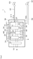
- Fig. 3 is a schematic view illustrating a partial configuration of the stirling engine 1 according to the variation of the first embodiment.
- parts that are identical or similar to those of the above-described embodiment are given identical reference numerals in the drawings, and description of these parts may be omitted.
- the stirling engine 1 of this variation is different from that of the first embodiment in including a dual-purpose path 55 instead of the connection route 51 and the operating fluid passage 53.
- the dual-purpose path 55 is a pipe member branched into two at an intermediate portion thereof, and an end (first end) 55a of one of the branched passages (branched passage) is connected to a crank box 11.
- the one end 55a of this branched passage of the dual-purpose path 55 is open to the crank box 11.
- the other end (second end) 55b of the other branched passage (branched passage 55e) of the dual-purpose path 55 is connected to the crankcase 9.
- This end 55b of the other branched passage 55e of the dual-purpose path 55 is open in the crankcase 9.
- the branched passage 55e of the other dual-purpose path 55 is disposed outside the crankcase 9.
- An intermediate portion of the branched passage 55e is provided with a valve 52 for opening and closing a channel in the branched passage 55e.
- a valve 54 is disposed at an open-side end (third end) in a non-branched portion of the dual-purpose path 55.
- a passage for allowing the first space S11 and the second space S9 to communicate with each other (corresponding to the connection route 51) and a passage for distributing operating fluid in filling and discharging the operating fluid (corresponding to the operating fluid passage 53) can be constituted by one passage, and thus, the passage can be simplified.
- FIG. 4 is a schematic view illustrating a partial configuration of the stirling engine 1 according to the second embodiment.
- parts that are identical or similar to those of the above-described embodiment are given identical reference numerals in the drawings, and description of these parts may be omitted.
- the stirling engine 1 of this embodiment includes a first filling/discharging path (first path) 61, a second filling/discharging path (second path) 62, a valve 63, and a valve 64.
- the first filling/discharging path 61 is a passage for distributing operating fluid in filling a first space S11 with operating fluid and discharging operating fluid from the first space S11.
- the first filling/discharging path 61 of this embodiment is a pipe member having a circular cross section, and a channel in which operating fluid flows is formed inside the first filling/discharging path 61.
- One end 61a of the first filling/discharging path 61 is connected to a side surface of a crank box 11 and is open (has an opening) to the first space S11.
- the first filling/discharging path 61 extends from the side surface of the crank box 11 toward the outside of a crankcase 9.
- the other end of the first filling/discharging path 61 is disposed outside the crankcase 9, and is open (has an opening) to the outside of the crankcase 9.
- the second filling/discharging path 62 is a passage for distributing operating fluid in filling a second space S9 with operating fluid and in discharging the operating fluid from the second space S9.
- the second filling/discharging path 62 of this embodiment is a pipe member having a circular cross section, and a channel in which operating fluid flows is formed inside the second filling/discharging path 62.
- the second filling/discharging path 62 is disposed outside the crankcase 9.
- One end 62a of the second filling/discharging path 62 is connected to the bottom surface of the crankcase 9, and is open (has an opening) to the second space S9.
- the other end of the second filling/discharging path 62 is disposed outside the crankcase 9, and is open (has an opening) to the outside of the crankcase 9.
- a ratio between a channel area of the channel of the first filling/discharging path 61 and a channel area of the channel of the second filling/discharging path 62 is set in consideration of a ratio between a volume of a portion filled with operating fluid by supplying the operating fluid to the first space S11 and a volume of a portion filled with operating fluid by supplying the operating fluid to the second space S9.
- the ratio between the channel area of the channel of the first filling/discharging path 61 and the channel area of the channel of the second filling/discharging path 62 can be set to be substantially equal to the ratio described above.
- the valve 63 is a valve capable of opening and closing the channel in the first filling/discharging path 61.
- the valve 63 is disposed at the other end of the first filling/discharging path 61.
- the valve 64 is a valve capable of opening and closing the channel in the second filling/discharging path 62.
- the valve 64 is disposed at the other end of the second filling/discharging path 62.
- filling the first space S11 and the second space S9 with operating fluid is performed in the following manner, for example.
- a vessel e.g., cylinder
- the valve 63 and the valve 64 are opened substantially at the same time so that the operating fluid is supplied to the first space S11 and the second space S9 at an appropriate flow rate.
- the ratio between the channel area of the channel of the first filling/discharging path 61 and the channel area of the channel of the second filling/discharging path 62 is set in consideration of the ratio between the volume of the portion filled with the operating fluid as described above, a balance can be easily kept between the pressure of the first space S11 and the pressure of the second space S9 by appropriately adjusting the flow rate of supply of the operating fluid, for example. Accordingly, these spaces can be quickly filled with the operating fluid without damage of the oil seals 21, 22, and 23.
- the stirling engine 1 of this embodiment includes, as the paths described above, the first filling/discharging path 61 and the second filling/discharging path 62.
- operating fluid can be supplied from each of the other end of the first filling/discharging path 61 and the other end of the second filling/discharging path 62 at an appropriate flow rate when necessary in consideration of the rate of the volume of the portion filled with operating fluid supplying the operating fluid to the first space S11 and the volume of the portion filled with operating fluid by supplying the operating fluid to the second space S9. Accordingly, these spaces can be filled with operating fluid with a balance kept between the pressure of the first space S11 and the pressure of the second space S9.
- setting is made in consideration of the ratio of the volume between the portion filled with operating fluid by supplying the operating fluid to the first space S11 and the volume of the portion filled with operating fluid by supplying the operating fluid to the second space S9.
- the state in which a balance is kept between the pressure of the first space S11 and the pressure of the second space S9 can be easily obtained by appropriately adjusting the rate of supplying operating fluid, for example.
- these spaces can be quickly filled with operating fluid easily.
- operating fluid can be easily discharged from the spaces.
- FIG. 5 is a schematic view illustrating a partial configuration of the stirling engine 1 according to the third embodiment.
- parts that are identical or similar to those of the above-described embodiments are given identical reference numerals in the drawings, and description of these parts may be omitted.
- the stirling engine 1 of this embodiment includes a first filling/discharging path (first path) 71, a second filling/discharging path (second path) 72, a valve 73, a valve 74, and a throttle 75.
- the first filling/discharging path 71 is a passage for distributing operating fluid in filling a first space S11 with operating fluid and discharging the operating fluid from the first space S11.
- the first filling/discharging path 71 of this embodiment is a pipe member having a circular cross section, and a channel in which operating fluid flows is formed inside the first filling/discharging path 71.
- One end 71a of the first filling/discharging path 71 is connected to a side surface of a crank box 11 and is open to the first space S11.
- the first filling/discharging path 71 extends from a side surface of the crank box 11 toward the outside of a crankcase 9.
- the other end of the first filling/discharging path 71 is disposed outside the crankcase 9, and is open to the outside of the crankcase 9.
- the second filling/discharging path 72 is a passage for distributing operating fluid in filling a second space S9 with operating fluid and discharging the operating fluid from the second space S9.
- the second filling/discharging path 72 of this embodiment is a pipe member having a circular cross section, and a channel in which operating fluid flows is formed inside the second filling/discharging path 72.
- the second filling/discharging path 72 is disposed outside the crankcase 9.
- One end 72a of the second filling/discharging path 72 is connected to the bottom surface of the crankcase 9, and is open to the second space S9.
- the other end of the second filling/discharging path 72 is disposed outside the crankcase 9, and is open to the outside of the crankcase 9.
- a channel area of the channel of the first filling/discharging path 71 is substantially equal to a channel area of the channel of the second filling/discharging path 72.
- the valve 73 is a valve capable of opening and closing a channel in the first filling/discharging path 71.
- the valve 73 is disposed at the other end of the first filling/discharging path 71.
- the valve 74 is a valve capable of opening and closing the channel in the second filling/discharging path 72.
- the valve 74 is disposed at the other end of the second filling/discharging path 72.
- the throttle 75 restricts a channel area of a channel in which the throttle 75 is disposed.
- the throttle 75 is disposed in an intermediate portion of the second filling/discharging path 72.
- the throttle 75 of this embodiment is configured to set a channel area in the second filling/discharging path 72 at a predetermined channel area. This channel area is appropriately set in consideration of various factors such as a ratio between a volume of a portion filled with operating fluid by supplying the operating fluid to the first space S11 and a volume of a portion filled with operating fluid by supplying the operating fluid to the second space S9, lengths of the first filling/discharging path 71 and the second filling/discharging path 72, and the pressure and temperature, for example, of operating fluid to be supplied.
- the throttle 75 is disposed in the second filling/discharging path 72.
- the throttle 75 may be disposed in the first filling/discharging path 71.
- filling the first space S11 and the second space S9 with operating fluid is performed in the following manner, for example. Specifically, a vessel enclosing operating fluid is connected to the other end of the first filling/discharging path 71 and the other end of the second filling/discharging path 72, and the valve 73 and the valve 74 are opened substantially at the same time so that the operating fluid is supplied to the first space S11 and the second space S9 at an appropriate flow rate.
- the stirling engine 1 of this embodiment includes, as the paths described above, the first filling/discharging path 71 and the second filling/discharging path 72. At least one of the first filling/discharging path 71 and the second filling/discharging path 72 is provided with the throttle 75 for restricting a channel area of the channel.
- a stirling engine 1 according to a fourth embodiment will now be described with reference to Fig. 6 .
- Fig. 6 is a schematic view illustrating a partial configuration of the stirling engine 1 according to the fourth embodiment.
- parts that are identical or similar to those of the above-described embodiments are given identical reference numerals in the drawings, and description of these parts may be omitted.
- the stirling engine 1 of this embodiment includes a first filling/discharging path 71, a second filling/discharging path 72, a valve 73, a valve 74, a variable throttle 85, a pressure difference sensor 86, and a control device 87.
- the variable throttle 85 is configured to adjust a channel area of a channel in which the variable throttle 85 is disposed.
- the variable throttle 85 is disposed in an intermediate portion of the second filling/discharging path 72.
- the variable throttle 85 changes a channel area of the channel (the degree of the throttle) in a plurality of stages or steplessly in accordance with an instruction signal from the control device 87.
- the variable throttle 85 is disposed in the second filling/discharging path 72.
- the variable throttle 85 may be provided in the first filling/discharging path 71.
- the pressure difference sensor 86 is a sensor for detecting a difference between the pressure of the first space S11 and the pressure of the second space S9. A detection result of the pressure difference sensor 86 is sent to the control device 87 as a detection signal.
- the control device 87 monitors a detection result of the pressure difference sensor 86 and adjusts the state of the variable throttle 85 automatically in accordance with the detection result to perform control of adjusting a channel area in the second filling/discharging path 72.
- the control device 87 is configured as a computer, and includes, for example, a CPU, a ROM, and RAM.
- the ROM records (stores) an appropriate operation program for causing the variable throttle 85 to operate.
- the control device 87 serves as an instruction section for causing the variable throttle 85 to operate appropriately in accordance with a pressure difference between the first space S11 and the second space S9 and to send an instruction for adjusting a channel area.
- the control device 87 receives a detection result of the pressure difference sensor 86, that is, information on a pressure difference between the first space S11 and the second space S9 as a detection signal regularly or irregularly.
- the control device 87 of this embodiment In the case of filling the first space S11 and the second space S9 with operating fluid, if the pressure of the second space S9 is lower than the pressure of the first space S11, the control device 87 of this embodiment outputs an instruction signal for increasing the opening degree of the variable throttle 85 from the current degree to the variable throttle 85, based on the pressure difference acquired from the pressure difference sensor 86. On the other hand, if the pressure of the second space S9 is higher than the pressure of the first space S11, the control device 87 outputs an instruction signal for reducing the opening degree of the variable throttle 85 from the current degree to the variable throttle 85.
- This feedback control is repeated so that the channel area ratio between the first filling/discharging path 71 and the second filling/discharging path 72 to a preferable ratio for sufficiently reducing a difference between the pressure of the first space S11 and the pressure of the second space S9.
- operating fluid continues to be supplied through the first filling/discharging path 71 and the second filling/discharging path 72 so that the first space S11 and the second space S9 can be filled with operating fluid with a balance automatically kept between the pressure of the first space S11 and the pressure of the second space S9 without a complicated calculation.
- filling with the operating fluid can be quickly performed without damage of the oil seals 21, 22, and 23, for example.
- the opening degree of the variable throttle 85 is controlled in the direction opposite to that described above.
- the stirling engine 1 of this embodiment includes, as the paths described above, the first filling/discharging path 71 and the second filling/discharging path 72.
- the stirling engine 1 includes the variable throttle 85 as a throttle for restricting the channel area. This variable throttle 85 is configured to enable adjustment of the channel area of this channel.
- pressure adjustment can be flexibly performed in accordance with various situations.
- the stirling engine 1 of this embodiment further includes the pressure difference sensor 86 and the control device 87.
- the pressure difference sensor 86 detects a difference between the pressure of the first space S11 and the pressure of the second space S9.
- the control device 87 controls a state of the variable throttle 85.
- one end of the operating fluid passage 53 is open to the second space S9.
- the present invention is not limited to this embodiment.
- one end of the operating fluid passage (corresponding to the operating fluid passage 53) may be open to the first space S11.
- a lubrication passage for use in filling the crank box 11 with lubricating oil may be used as the operating fluid passage 53.
- the cylinder enclosing operating fluid is connected to the other end of the operating fluid passage 53 or other places to thereby supply the operating fluid to the first space S11 and the second space S9.
- the source of operating fluid is not limited to this.
- operating fluid may be pumped to the first space S11 and the second space S9 with a pump from a vessel (tank) enclosing operating fluid.
- operating fluid may be supplied to the first space S11 and the second space S9 from the same source or different sources.
- the throttle 75 and the variable throttle 85 are provided as structures for restricting the channel area of the channel through which operating fluid passes in supplying and discharging the operating fluid, respectively. That is, instead of the throttle, a "valve" capable of restricting a channel area may be provided. In this case, for example, the valves 63 and 64 (valves 73 and 74) may have the function of restricting channel areas and serve as the "valve.”
- the first space S11 and the second space S9 are connected to each other with the pipe-like connection route 51.
- the present invention is not limited to this embodiment.
- a columnar plug in which a channel capable of connecting and disconnecting the first space S11 and the second space S9 is formed may be provided to penetrate the crank box 11 and the crankcase 9. In this case, this plug is operated by an operator from outside the crankcase 9 so that the first space S11 and the second space S9 are switched between connection and disconnection.
- a valve capable of connecting and disconnecting the first space S11 and the second space S9 may be provided to penetrate the crank box 11.
- valve in supplying and discharging operating fluid, valve is opened or closed to switch the first space S11 and the second space S9 between connection and disconnection.
- this valve is constituted by a first check valve closed to the first space S11 and a second check valve closed to the second space S9, when a pressure difference occurs between the first space S11 and the second space S9, one of these check valves is opened so that the first space S11 and the second space S9 can be switched between connection and disconnection without an operation of the valve from outside the crankcase 9.
- the stirling engine 1 is a so-called ⁇ type engine.
- the present invention is not limited to this, and instead, an ⁇ type or a ⁇ type engine may be employed.
Landscapes
- Engineering & Computer Science (AREA)
- Chemical & Material Sciences (AREA)
- Combustion & Propulsion (AREA)
- Mechanical Engineering (AREA)
- General Engineering & Computer Science (AREA)
- Engine Equipment That Uses Special Cycles (AREA)
Applications Claiming Priority (2)
| Application Number | Priority Date | Filing Date | Title |
|---|---|---|---|
| JP2017050634A JP6626468B2 (ja) | 2017-03-15 | 2017-03-15 | スターリングエンジン |
| PCT/JP2018/009088 WO2018168662A1 (ja) | 2017-03-15 | 2018-03-08 | スターリングエンジン |
Publications (2)
| Publication Number | Publication Date |
|---|---|
| EP3587782A1 true EP3587782A1 (de) | 2020-01-01 |
| EP3587782A4 EP3587782A4 (de) | 2020-12-16 |
Family
ID=63522911
Family Applications (1)
| Application Number | Title | Priority Date | Filing Date |
|---|---|---|---|
| EP18766615.1A Withdrawn EP3587782A4 (de) | 2017-03-15 | 2018-03-08 | Stirlingmotor |
Country Status (3)
| Country | Link |
|---|---|
| EP (1) | EP3587782A4 (de) |
| JP (1) | JP6626468B2 (de) |
| WO (1) | WO2018168662A1 (de) |
Families Citing this family (1)
| Publication number | Priority date | Publication date | Assignee | Title |
|---|---|---|---|---|
| JP6635905B2 (ja) * | 2016-10-18 | 2020-01-29 | ヤンマー株式会社 | スターリングエンジン |
Family Cites Families (3)
| Publication number | Priority date | Publication date | Assignee | Title |
|---|---|---|---|---|
| SE467837B (sv) * | 1990-04-03 | 1992-09-21 | Carlqvist Stig G Motor Consult | Energiomvandlare, som arbetar enligt stirling- ericsson eller liknande termodynamiska cykler |
| US6263671B1 (en) | 1997-11-15 | 2001-07-24 | Wayne T Bliesner | High efficiency dual shell stirling engine |
| JP4873647B2 (ja) * | 2007-09-07 | 2012-02-08 | 株式会社eスター | スターリングエンジン |
-
2017
- 2017-03-15 JP JP2017050634A patent/JP6626468B2/ja not_active Expired - Fee Related
-
2018
- 2018-03-08 EP EP18766615.1A patent/EP3587782A4/de not_active Withdrawn
- 2018-03-08 WO PCT/JP2018/009088 patent/WO2018168662A1/ja not_active Ceased
Also Published As
| Publication number | Publication date |
|---|---|
| WO2018168662A1 (ja) | 2018-09-20 |
| EP3587782A4 (de) | 2020-12-16 |
| JP2018155117A (ja) | 2018-10-04 |
| JP6626468B2 (ja) | 2019-12-25 |
Similar Documents
| Publication | Publication Date | Title |
|---|---|---|
| US7603858B2 (en) | Harmonic engine | |
| US6487858B2 (en) | Method and apparatus for diminishing the consumption of fuel and converting reciprocal piston motion into rotary motion | |
| JP4285338B2 (ja) | スターリングエンジン | |
| US7836691B2 (en) | Heat engine | |
| WO2014012586A1 (en) | Heat to mechanical energy converter | |
| RU2736116C1 (ru) | Поршневой насос | |
| JP5525371B2 (ja) | 外燃式クローズドサイクル熱機関 | |
| US4633668A (en) | Two piston V-type Stirling engine | |
| JP6626468B2 (ja) | スターリングエンジン | |
| US20250129977A1 (en) | Compressor Device and a Cooling Device Having the Compressor Device | |
| US8479507B2 (en) | Piston engine | |
| US4968219A (en) | Multi-stage compressor with seal heating | |
| WO2008156913A2 (en) | Harmonic engine | |
| RU2755207C1 (ru) | Криогенный поршневой насос | |
| JP6726079B2 (ja) | スターリングエンジン | |
| US20210222592A1 (en) | Method and apparatus for converting heat energy to mechanical energy | |
| JP6817856B2 (ja) | スターリングエンジン | |
| US20150013333A1 (en) | Heat recovery system for an internal combustion engine | |
| JP2011117411A (ja) | 外燃式クローズドサイクル熱機関 | |
| Caughley et al. | Development of a diaphragm pressure wave generator for cryocoolers | |
| JP6827343B2 (ja) | スターリングエンジン及びその潤滑油排出方法 | |
| JPH09287518A (ja) | 高温側に熱膨張室を持つスターリングエンジン | |
| JP6713403B2 (ja) | 出力取り出し装置、及びスターリングエンジン | |
| EP3530921A1 (de) | Stirlingmotor | |
| WO2019225640A1 (ja) | スターリングエンジン |
Legal Events
| Date | Code | Title | Description |
|---|---|---|---|
| STAA | Information on the status of an ep patent application or granted ep patent |
Free format text: STATUS: THE INTERNATIONAL PUBLICATION HAS BEEN MADE |
|
| PUAI | Public reference made under article 153(3) epc to a published international application that has entered the european phase |
Free format text: ORIGINAL CODE: 0009012 |
|
| STAA | Information on the status of an ep patent application or granted ep patent |
Free format text: STATUS: REQUEST FOR EXAMINATION WAS MADE |
|
| 17P | Request for examination filed |
Effective date: 20190924 |
|
| AK | Designated contracting states |
Kind code of ref document: A1 Designated state(s): AL AT BE BG CH CY CZ DE DK EE ES FI FR GB GR HR HU IE IS IT LI LT LU LV MC MK MT NL NO PL PT RO RS SE SI SK SM TR |
|
| AX | Request for extension of the european patent |
Extension state: BA ME |
|
| DAV | Request for validation of the european patent (deleted) | ||
| DAX | Request for extension of the european patent (deleted) | ||
| RAP1 | Party data changed (applicant data changed or rights of an application transferred) |
Owner name: YANMAR POWER TECHNOLOGY CO., LTD. |
|
| A4 | Supplementary search report drawn up and despatched |
Effective date: 20201112 |
|
| RIC1 | Information provided on ipc code assigned before grant |
Ipc: F02G 1/05 20060101ALI20201106BHEP Ipc: F02G 1/043 20060101ALI20201106BHEP Ipc: F02G 1/053 20060101AFI20201106BHEP Ipc: F02G 1/045 20060101ALI20201106BHEP |
|
| STAA | Information on the status of an ep patent application or granted ep patent |
Free format text: STATUS: THE APPLICATION HAS BEEN WITHDRAWN |
|
| 18W | Application withdrawn |
Effective date: 20210527 |