EP3587832B1 - Boîtier de vanne d'asservissement - Google Patents
Boîtier de vanne d'asservissement Download PDFInfo
- Publication number
- EP3587832B1 EP3587832B1 EP18461568.0A EP18461568A EP3587832B1 EP 3587832 B1 EP3587832 B1 EP 3587832B1 EP 18461568 A EP18461568 A EP 18461568A EP 3587832 B1 EP3587832 B1 EP 3587832B1
- Authority
- EP
- European Patent Office
- Prior art keywords
- plate
- return
- nozzle
- nozzle housing
- passage
- Prior art date
- Legal status (The legal status is an assumption and is not a legal conclusion. Google has not performed a legal analysis and makes no representation as to the accuracy of the status listed.)
- Active
Links
Images


Classifications
-
- F—MECHANICAL ENGINEERING; LIGHTING; HEATING; WEAPONS; BLASTING
- F16—ENGINEERING ELEMENTS AND UNITS; GENERAL MEASURES FOR PRODUCING AND MAINTAINING EFFECTIVE FUNCTIONING OF MACHINES OR INSTALLATIONS; THERMAL INSULATION IN GENERAL
- F16K—VALVES; TAPS; COCKS; ACTUATING-FLOATS; DEVICES FOR VENTING OR AERATING
- F16K11/00—Multiple-way valves, e.g. mixing valves; Pipe fittings incorporating such valves
- F16K11/02—Multiple-way valves, e.g. mixing valves; Pipe fittings incorporating such valves with all movable sealing faces moving as one unit
- F16K11/06—Multiple-way valves, e.g. mixing valves; Pipe fittings incorporating such valves with all movable sealing faces moving as one unit comprising only sliding valves, i.e. sliding closure elements
- F16K11/065—Multiple-way valves, e.g. mixing valves; Pipe fittings incorporating such valves with all movable sealing faces moving as one unit comprising only sliding valves, i.e. sliding closure elements with linearly sliding closure members
- F16K11/07—Multiple-way valves, e.g. mixing valves; Pipe fittings incorporating such valves with all movable sealing faces moving as one unit comprising only sliding valves, i.e. sliding closure elements with linearly sliding closure members with cylindrical slides
- F16K11/0712—Multiple-way valves, e.g. mixing valves; Pipe fittings incorporating such valves with all movable sealing faces moving as one unit comprising only sliding valves, i.e. sliding closure elements with linearly sliding closure members with cylindrical slides comprising particular spool-valve sealing means
-
- F—MECHANICAL ENGINEERING; LIGHTING; HEATING; WEAPONS; BLASTING
- F15—FLUID-PRESSURE ACTUATORS; HYDRAULICS OR PNEUMATICS IN GENERAL
- F15B—SYSTEMS ACTING BY MEANS OF FLUIDS IN GENERAL; FLUID-PRESSURE ACTUATORS, e.g. SERVOMOTORS; DETAILS OF FLUID-PRESSURE SYSTEMS, NOT OTHERWISE PROVIDED FOR
- F15B13/00—Details of servomotor systems ; Valves for servomotor systems
- F15B13/02—Fluid distribution or supply devices characterised by their adaptation to the control of servomotors
- F15B13/04—Fluid distribution or supply devices characterised by their adaptation to the control of servomotors for use with a single servomotor
- F15B13/042—Fluid distribution or supply devices characterised by their adaptation to the control of servomotors for use with a single servomotor operated by fluid pressure
- F15B13/043—Fluid distribution or supply devices characterised by their adaptation to the control of servomotors for use with a single servomotor operated by fluid pressure with electrically-controlled pilot valves
- F15B13/0438—Fluid distribution or supply devices characterised by their adaptation to the control of servomotors for use with a single servomotor operated by fluid pressure with electrically-controlled pilot valves the pilot valves being of the nozzle-flapper type
-
- F—MECHANICAL ENGINEERING; LIGHTING; HEATING; WEAPONS; BLASTING
- F15—FLUID-PRESSURE ACTUATORS; HYDRAULICS OR PNEUMATICS IN GENERAL
- F15B—SYSTEMS ACTING BY MEANS OF FLUIDS IN GENERAL; FLUID-PRESSURE ACTUATORS, e.g. SERVOMOTORS; DETAILS OF FLUID-PRESSURE SYSTEMS, NOT OTHERWISE PROVIDED FOR
- F15B21/00—Common features of fluid actuator systems; Fluid-pressure actuator systems or details thereof, not covered by any other group of this subclass
- F15B21/04—Special measures taken in connection with the properties of the fluid
- F15B21/041—Removal or measurement of solid or liquid contamination, e.g. filtering
-
- F—MECHANICAL ENGINEERING; LIGHTING; HEATING; WEAPONS; BLASTING
- F16—ENGINEERING ELEMENTS AND UNITS; GENERAL MEASURES FOR PRODUCING AND MAINTAINING EFFECTIVE FUNCTIONING OF MACHINES OR INSTALLATIONS; THERMAL INSULATION IN GENERAL
- F16K—VALVES; TAPS; COCKS; ACTUATING-FLOATS; DEVICES FOR VENTING OR AERATING
- F16K31/00—Actuating devices; Operating means; Releasing devices
- F16K31/02—Actuating devices; Operating means; Releasing devices electric; magnetic
- F16K31/06—Actuating devices; Operating means; Releasing devices electric; magnetic using a magnet, e.g. diaphragm valves, cutting off by means of a liquid
- F16K31/0603—Multiple-way valves
- F16K31/061—Sliding valves
- F16K31/0613—Sliding valves with cylindrical slides
Definitions
- the present invention relates to a housing for a single stage air servo valve.
- Servo valves are well-known in the art and can be used to control the flow and pressure of fluid to an actuator via a spool valve.
- a flapper is deflected by an armature connected to an electric motor away or towards one or more nozzle(s), which controls the fluid flow and pressure to the valve. Deflection of the flapper can control the amount of fluid injected from the nozzle(s), and thus the amount of fluid communicated to the actuator via the spool valve. In this way, servo valves allow precise control of actuator movement.
- a return nozzle is in fluid communication with the atmosphere. Under normal operating conditions, air continuously flows from the return nozzle to the atmosphere. This protects the device from external contaminants such as sand and dust. However, when there is no or low flow from the return nozzle, for example when the device is not operational, there is a high risk of contamination from particles of sand or dust flowing from the atmosphere into and through the return nozzle. These particles can enter the servo valve and the actuator, which may reduce control, block flow or movement, and/or damage components.
- EP 3205913 A1 discloses a prior art nozzle housing according to the preamble of claim 1.
- a nozzle housing for a servo valve, the nozzle housing comprising a circumferential wall defining a return passage extending along a longitudinal axis for holding a return nozzle, the return passage having an opening for fluid communication with a spool valve and a return port for fluid communication with atmosphere, a first plate extending across the return passage, the first plate engaged with the circumferential wall and disposed between the opening and the return port, and a second plate extending across the return passage, the second plate engaged with the circumferential wall and disposed between the first plate and the return port, wherein the first plate has at least one first aperture, and the second plate has at least one second aperture that is misaligned with the at least one first aperture such that there is no linear axial flow path between the return port and the opening.
- misaligned or “offset” it is meant that no portion of an aperture of one plate is aligned with any portion of an aperture of the other plate when viewed along the axial direction (e.g. from the return port, along the axis towards the opening). This misalignment or offset therefore provides no linear axial flow path through the apertures. As such, there is no linear axial flow path from the return port to the opening.
- engaged it is meant that the plates are substantially in contact with the circumferential wall around the entire circumference, such that few or no gaps are formed, and any such gaps are much smaller than the apertures.
- the at least one first aperture may comprise a plurality of first apertures and the at least one second aperture may comprise a plurality of second apertures.
- Each of the plurality of second apertures may be disposed an equal distance or circumferential angle from the two nearest first apertures.
- the first plate, the second plate and the nozzle housing may be made from the same material.
- At least one debris removal passage may extend through the circumferential wall, and the at least one debris removal passage may have an inlet axially between the first plate and the second plate.
- the at least one debris removal passage may comprise a plurality of circumferentially spaced debris removal passages.
- a separating ring may be disposed in the return passage between the first plate and the second plate, and the separating ring may comprise an annular wall having at least one opening extending radially therethrough and in fluid communication with the inlet of the at least one debris removal passage.
- a retention ring may be disposed between the second plate and the return port, and the retention ring may retain the first plate, the separating ring and the second plate in the return passage.
- the circumferential wall may comprise a stop, and the first plate may be disposed between the stop and the retention ring.
- Each of the first plate, the separating ring, the second plate and the retention ring may have at least one anti-rotation tab, and each anti-rotation tab may engage a groove in the circumferential wall.
- the first plate and the second plate may each have at least one anti-rotation tab, and each anti-rotation tab may engage a groove in the circumferential wall.
- the first plate and the second plate may be planar.
- the first plate and the second plate may extend radially across the return passage.
- the first plate, the separating ring, the second plate, the retention ring and the nozzle housing may be made from the same material.
- An embodiment of the present invention also provides a single stage air servo valve comprising the nozzle housing described above, wherein the nozzle housing comprises a flapper cavity and first and second nozzle cavities, the first nozzle cavity comprises the return passage, the second nozzle cavity comprises a supply passage, the supply passage has an inlet, an opening, and a supply nozzle disposed therebetween, and the return passage has a return nozzle disposed between the opening of the return passage and the first plate, and a flapper disposed in the flapper cavity between the opening of the supply passage and the opening of the return passage.
- the first and second nozzle cavities may be coaxial.
- a total cross-sectional area of the at least one first aperture may be at least five times greater than a cross-sectional area of an orifice of the return nozzle, and may be similar to that of the at least one first aperture.
- a total cross-sectional area of the at least one second aperture may be at least five times greater than a cross-sectional area of an orifice of the return nozzle.
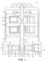
- the servo valve 1 comprises a flapper 2, an electric motor 4, and a nozzle housing 6.
- the electric motor 4 comprises coils 4a, permanent magnets 4b and an armature 4c.
- the coils 4a are in electrical communication with an electrical supply (not shown) and, when activated, interact with the permanent magnets 4b to move armature 4c, as is well-known in the art.
- the flapper 2 is disposed in a flapper cavity 2a in the nozzle housing 6 and is attached to the armature 4c.
- the flapper 2 is deflected by movement of the armature 4c.
- the nozzle housing 6 comprises a nozzle cavity 8 extending along a longitudinal axis A, a supply passage 8a and a return passage 8b.
- the supply passage 8a may be defined by a circumferential wall 9a.
- the return passage may be defined by a circumferential wall 9b.
- the supply passage 8a and the return passage 8b may be co-axial.
- a supply port 10 provides an inlet to the supply passage 8a, and an opening 11.
- a control port 12 is fluidly between the supply passage 8a and the return passage 8b.
- An opening 13 provides an inlet for the return passage 8b, and a return port 14 provides an outlet for the return passage 8b.
- a supply nozzle 16 is housed within the supply passage 8a via interference fit therewith, and a return nozzle 18 is housed within the return passage 8b via interference fit therewith.
- the flapper 2 comprises a blocking element 20 at an end thereof and proximate the control port 12, and is disposed between the supply passage 8a and the return passage 8b.
- the supply port 10 allows for the communication of air to the supply nozzle 16.
- the blocking element 20 selectively interacts with the supply nozzle 16 to meter the flow of air from the supply nozzle 16 to a spool valve (not shown) via the control port 12.
- the blocking element 20 also selectively interacts with the return nozzle 18 to meter the flow of air from the control port 12 through the return nozzle 18 via the opening 13 to the return port 14.
- the return port 14 is in fluid communication with the atmosphere.
- the electric motor 4 is used to control a deflection of the blocking element 20 to vary the interaction between the blocking element 20 and the supply and return nozzles 16 and 18, thus modulating the pressure of air to the control port 12.
- a return passage 8b in accordance with an embodiment of the present invention is provided with an insert 100 comprising a first plate 102 and a second plate 106.
- Each of the plates 102 and 106 may extend radially across the return passage 8b to interact with a flow of air therethrough.
- Each of the plates 102 and 106 may engage with the circumferential wall 9b of the return passage 8b such that few or no gaps are provided between the first plate 102 and the circumferential wall 9b or between the second plate 106 and the circumferential wall 9b.
- the first plate 102 is provided with at least one aperture 102a
- the second plate 106 is provided with at least one aperture 106a.
- the apertures 102a and 106a allow air to flow through the first plate 102 and the second plate 106.
- the at least one aperture 106a of the second plate 106 is misaligned with the at least one aperture 102a of the first plate 102. In other words, the at least one aperture 106a of the second plate 106 is circumferentially and/or radially offset from the at least one aperture of the first plate 102.
- the first plate 102a may have a plurality of apertures 102a and the second plate 106 may have a plurality of apertures 106a.
- all of the plurality of apertures 102a of the first plate 102 are misaligned with all of the plurality of apertures 106a of the second plate 106 such that no linear axial flow path is provided between any of the plurality of apertures 102a of the first plate 102 and any of the plurality of apertures 106a of the second plate 106.
- the first plate 102 may be provided with one, two, three, four or more apertures 102a.
- the second plate 106 may be provided with one, two, three, four or more apertures 106a.
- a total cross-sectional area of the apertures 102a of the first plate 102 may be substantially equal to a total cross-sectional area of the apertures 106a of the second plate 106.
- a total cross-sectional area of the first and/or second plurality of apertures 102a, 106a may be at least five times greater than a cross-sectional area of an orifice of the return nozzle 18. This ensures that the pressure drop caused by the plates 102, 106 is negligible (compared to that caused by the return nozzle 18), and that the normal operation of the servo valve is not affected.
- the first plate 102 and the second plate 106 may be provided with the same number of apertures 102a and 106a.
- the apertures 102a and 106a may be disposed an equal distance from the longitudinal axis A, and/or may be equally circumferentially spaced.
- the apertures 102a and 106a may all have the same area.
- the apertures 106a of the second plate 106 may be misaligned with the apertures 102a of the first plate 102 such that each aperture 102a of the first plate 102 is misaligned from the two nearest apertures 106a of the second plate 106 by an equal distance or circumferential angle.
- the first plate 102 and the second plate 106 are provided with the same arrangement of four apertures 102a, 106a.
- Each aperture 102a, 106a is equally radially spaced from the longitudinal axis A, and each aperture 102a, 106a is equally circumferentially spaced by 90 degrees.
- the arrangement of apertures 106a of the second plate 106 is rotated by 45 degrees relative to the arrangement of apertures 102a on the first plate 102, such that each aperture 106a of the second plate 106 is offset or misaligned from the two nearest apertures 102a of the first plate 102 by 45 degrees.
- each plate in the illustrated embodiment, it is to be understood that any number of equally circumferentially spaced apertures may be provided.
- one, two, three, five, or six equally circumferentially apertures 102a, 106a may be provided on each plate 102, 106, and the arrangement of apertures 106a on the second plate 106 may be misaligned or rotated relative to the arrangement of apertures 102a on the first plate 102 by 90 degrees, 60 degrees, 36 degrees or 30 degrees respectively, such that each aperture 102a of the first plate 102 is misaligned from the two nearest apertures 106a of the second plate 106 by an equal distance or circumferential angle.
- the nozzle housing 6 further comprises at least one debris removal passage 112 extending through the circumferential wall 9b.
- the debris removal passage 112 comprises an inlet 114 axially between the first plate 102 and the second plate 106.
- any particles in the air entering from the atmosphere that pass through an aperture 106a in the second plate 106 may not flow directly through an aperture 102a in the first plate 102, as the apertures 102a and 106a are not aligned in the direction of flow, i.e. along the longitudinal axis A.
- the particles may instead be impeded from passing through the return passage 8b by contacting a transverse surface of the first plate 102, and may fall, under gravity, to the bottom of the return passage 8b, or into the debris removal passage 112. Once the flow of air from the return nozzle 18 to the atmosphere resumes, the particles may be ejected via the debris removal passage 112 to the atmosphere by the flow of air.
- a separating ring 104 may be disposed in the return passage 8b between the first plate 102 and the second plate 106.
- the separating ring 104 may be housed in the return passage 8b by an interference fit.
- the separating ring 104 may space the first plate 102 from the second plate 106.
- the separating ring 104 may be provided with an annular wall 104a having at least one opening 110 extending radially therethrough.
- the annular wall 104a may engage with the circumferential wall 9b of the return passage 8b such that few or no gaps are provided between the annular wall 104a of the separating ring 104 and the circumferential wall 9b of the return passage 9b.
- the at least one opening 110 may be aligned with and/or be in fluid communication with the inlet 114 of the debris removal passage 112.
- the separating ring 104 comprises two or more openings 110 extending radially through the annular wall 104a, and the nozzle housing 6 is provided with two or more debris removal passages 112, each having an inlet 114 aligned with and/or in fluid communication with one of the two or more openings 110 of the separating ring 104.
- Multiple circumferentially spaced debris removal passages 112 allow the servo valve 1 to be installed or operate in various orientations while still allowing particles to be removed from the return passage 8 via gravity. Particles may be trapped in the area defined by the separating ring 104 until flow from the return nozzle 18 to the atmosphere resumes.
- a retention ring 108 may be disposed between the second plate 106 and the return port 14.
- the retention ring 108 may retain the first plate 102, the separating ring 104 and the second plate 106 in the return passage 8b.
- the return passage 8b may be provided with a stop 116 against which the first plate 102 may abut.
- the retention ring 108 may retain the first plate 102, the separating ring 104 and the second plate 106 against the stop 116 via interference fit with the return passage 8b.
- the retaining ring 108 has an opening extending axially therethrough to provide fluid communication between the at least one aperture 102a of the first plate 102 and the atmosphere.
- the circumferential wall 9b of the return passage 8b may comprise a first portion 118 having a first diameter D1, and a second portion 120 co-axial with the first portion 118 having a second diameter D2 greater than the first diameter D1.
- the first portion 118 may house the return nozzle 18, via interference fit therewith.
- the second portion 120 may house the insert 100, via interference fit therewith.
- the first portion 118 and the second portion 120 may be joined by an annular wall providing the stop 116, against which the first plate 102 may be retained.
- the stop 116 may be provided by, for example, a circumferential ridge, fillet or groove in the circumferential wall 9b of the return passage 8b. In other embodiments, no stop 116 may be provided.
- the insert 100 may be retained only by interference fit with the return passage 8b.
- the insert 100 may be provided with at least one radially extending anti-rotation tab 122 configured to engage with at least one groove 124 provided in the circumferential wall 9b, to prevent rotation of the insert 100 and to prevent incorrect assembly. This ensures that the misalignment of the apertures 102a and 106a is maintained.
- first plate 102 and the second plate 106 are each provided with at least one anti-rotation tab 122, with each anti-rotation tab 122 engaging a groove 124 in the circumferential wall 9b to prevent either of the first plate 102 or the second plate 106 from rotating in situ.
- the groove 124 may extend axially along the circumferential wall 9b for the length of the insert 100, for example to stop 116.
- the first plate 102 and the second plate 106 are each provided with two anti-rotation tabs 122, each anti-rotation tab 122 engaging with one of two axially extending grooves 124 in the circumferential wall 9b.
- the separating ring 104 and/or the retention ring 108 may also be provided with one, two, or more anti-rotation tabs 122 to engage with the grooves 124.
- each of the first plate 102, the separating ring 104, the second plate 106 and the retention ring 108 are provided with two anti-rotation tabs 122, each of which are configured to engage one of two axially extending grooves 124 in the nozzle housing 6 to prevent rotation of the first plate 102, the separating ring 104, the second plate 106 or the retention ring 108.
- any or all of the first plate 102, the separating ring 104, the second plate 106 and the retention ring 108 may be provided with one or more anti-rotation tabs 122 to engage with the one or more grooves 124.
- the first plate 102, the separating ring 104, the second plate 106 and the retention ring 108 may all be made from the same material as the nozzle housing 6. This provides the insert 100 with the same thermal expansion coefficient as the surrounding nozzle housing 6, and ensures that few or no gaps are formed between the components of the insert 100 and the nozzle housing 6, thus preventing any air from being able bypass the insert 100, as the temperature fluctuates.
- the material may, for example, be any suitable non-magnetic metal, such as aluminium or stainless steel, e.g., austenitic stainless steel.
Landscapes
- Engineering & Computer Science (AREA)
- General Engineering & Computer Science (AREA)
- Mechanical Engineering (AREA)
- Physics & Mathematics (AREA)
- Fluid Mechanics (AREA)
- Chemical & Material Sciences (AREA)
- Analytical Chemistry (AREA)
- Servomotors (AREA)
Claims (15)
- Boîtier de buse (6) pour une vanne d'asservissement (1), le boîtier de buse (6) comprenant :une paroi circonférentielle (9b) définissant un passage de retour (8b) s'étendant le long d'un axe longitudinal (A) pour retenir une buse de retour (18), le passage de retour (8b) ayant une ouverture (13) pour une communication fluidique avec un distributeur à tiroir cylindrique et un port de retour (14) pour une communication fluide avec l'atmosphère ;caractérisé par :une première plaque (102) s'étendant à travers le passage de retour (8b), la première plaque (102) étant en prise avec la paroi circonférentielle (9b) et disposée entre l'ouverture (13) et le port de retour (14) ; etune seconde plaque (106) s'étendant à travers le passage de retour (8b), la seconde plaque (106) étant en prise avec la paroi circonférentielle (9b) et disposée entre la première plaque (102) et le port de retour (14), dans lequel la première plaque (102) a au moins une première ouverture (102a), et la seconde plaque (106) a au moins une seconde ouverture (106a) qui est désalignée par rapport à l'au moins une première ouverture (102a) de sorte qu'il n'y ait pas de chemin d'écoulement axial linéaire entre le port de retour (14) et l'ouverture (13).
- Boîtier de buse (6) selon la revendication 1, dans lequel l'au moins une première ouverture (102a) comprend une pluralité de premières ouvertures (102a) et l'au moins une seconde ouverture (106a) comprend une pluralité de secondes ouvertures (102a) .
- Boîtier de buse (6) selon la revendication 2, dans lequel chacune de la pluralité de secondes ouvertures (106a) est disposée à une distance ou à un angle circonférentiel (θ) égal des deux premières ouvertures (102a) les plus proches.
- Boîtier de buse (6) selon la revendication 1, 2 ou 3, dans lequel la première plaque (102), la seconde plaque (106) et le boîtier de buse (6) sont fabriqués à partir du même matériau.
- Boîtier de buse (6) selon une quelconque revendication précédente, comprenant en outre au moins un passage d'élimination de débris (112) s'étendant à travers la paroi circonférentielle (9b), l'au moins un passage d'élimination de débris (112) ayant une entrée (114) axialement entre la première plaque (102) et la seconde plaque (106).
- Boîtier de buse (6) selon la revendication 5, dans lequel l'au moins un passage d'élimination de débris (112) comprend une pluralité de passages d'élimination de débris (112) espacés circonférentiellement.
- Boîtier de buse (6) selon la revendication 5 ou 6, comprenant en outre une bague de séparation (104) disposée dans le passage de retour (9b) entre la première plaque (102) et la seconde plaque (106), dans lequel la bague de séparation (104) comprend une paroi annulaire (104a) ayant au moins une ouverture (110) s'étendant radialement à travers celle-ci et en communication fluidique avec l'entrée (114) de l'au moins un passage d'élimination de débris (112).
- Boîtier de buse (6) selon la revendication 7, comprenant en outre une bague de retenue (108) disposée entre la seconde plaque (106) et le port de retour (14), la bague de retenue (108) retenant la première plaque (102), la bague de séparation (104) et la seconde plaque (106) dans le passage de retour (8b).
- Boîtier de buse (6) selon la revendication 8, dans lequel la paroi circonférentielle (9b) comprend une butée (116), et la première plaque (102) est disposée entre la butée (116) et la bague de retenue (108).
- Boîtier de buse (6) selon la revendication 8 ou 9, dans lequel chacun parmi la première plaque (102), la bague de séparation (104), la seconde plaque (106) et la bague de retenue (108) a au moins une patte anti-rotation (122), chaque patte anti-rotation (122) venant en prise avec une rainure (124) dans la paroi circonférentielle (9b).
- Boîtier de buse (6) selon l'une quelconque des revendications 1 à 9, dans lequel la première plaque (102) et la seconde plaque (106) ont chacune au moins une patte anti-rotation (122), chaque patte anti-rotation (122) venant en prise avec une rainure (124) dans la paroi circonférentielle (9b).
- Boîtier de buse (6) selon une quelconque revendication précédente, dans lequel la première plaque (102) et la seconde plaque (106) sont planes.
- Vanne d'asservissement pneumatique à un seul étage (1) comprenant :le boîtier de buse (6) selon une quelconque revendication précédente, dans lequel le boîtier de buse (6) comprend une cavité de clapet (2a) et des première et seconde cavités de buse, dans laquelle la première cavité de buse comprend le passage de retour (8b), la seconde cavité de buse comprend un passage d'alimentation (8a), le passage d'alimentation (8a) a une entrée (10), une ouverture (11) et une buse d'alimentation (16) disposée entre elles, et le passage de retour (8b) a une buse de retour (18) disposée entre l'ouverture (13) du passage de retour (8b) et la première plaque (102) ; etun clapet (2) disposé dans la cavité de clapet (2a) entre l'ouverture (11) du passage d'alimentation (8a) et l'ouverture (13) du passage de retour (8b).
- Vanne d'asservissement (1) selon la revendication 13, dans laquelle une surface transversale totale de l'au moins une première ouverture (102a) est au moins cinq fois supérieure à une surface transversale d'un orifice de la buse de retour (18).
- Vanne d'asservissement (1) selon la revendication 13 ou 14, dans laquelle une surface transversale totale de l'au moins une seconde ouverture (106a) est au moins cinq fois supérieure à une surface transversale d'un orifice de la buse de retour (18).
Priority Applications (2)
| Application Number | Priority Date | Filing Date | Title |
|---|---|---|---|
| EP18461568.0A EP3587832B1 (fr) | 2018-06-24 | 2018-06-24 | Boîtier de vanne d'asservissement |
| US16/434,209 US10794499B2 (en) | 2018-06-24 | 2019-06-07 | Servo valve housing |
Applications Claiming Priority (1)
| Application Number | Priority Date | Filing Date | Title |
|---|---|---|---|
| EP18461568.0A EP3587832B1 (fr) | 2018-06-24 | 2018-06-24 | Boîtier de vanne d'asservissement |
Publications (2)
| Publication Number | Publication Date |
|---|---|
| EP3587832A1 EP3587832A1 (fr) | 2020-01-01 |
| EP3587832B1 true EP3587832B1 (fr) | 2024-04-03 |
Family
ID=62814979
Family Applications (1)
| Application Number | Title | Priority Date | Filing Date |
|---|---|---|---|
| EP18461568.0A Active EP3587832B1 (fr) | 2018-06-24 | 2018-06-24 | Boîtier de vanne d'asservissement |
Country Status (2)
| Country | Link |
|---|---|
| US (1) | US10794499B2 (fr) |
| EP (1) | EP3587832B1 (fr) |
Families Citing this family (3)
| Publication number | Priority date | Publication date | Assignee | Title |
|---|---|---|---|---|
| US11799391B2 (en) | 2021-03-13 | 2023-10-24 | Hamilton Sundstrand Corporation | Diode mounting ring with contact band inserts |
| US12009126B2 (en) * | 2021-03-13 | 2024-06-11 | Hamilton Sundstrand Corporation | Resistor support assembly with spring seat |
| US11949294B2 (en) | 2021-03-13 | 2024-04-02 | Hamilton Sundstrand Corporation | Resistor plate assembly with contact bands |
Family Cites Families (14)
| Publication number | Priority date | Publication date | Assignee | Title |
|---|---|---|---|---|
| US2655904A (en) | 1951-05-28 | 1953-10-20 | Northrop Aircraft Inc | Hydraulic gain control |
| US3498308A (en) * | 1968-09-05 | 1970-03-03 | Us Navy | Armature-torsion spring suspension assembly |
| US3556150A (en) * | 1969-05-12 | 1971-01-19 | Borg Warner | Electro hydraulic servovalve |
| US4131130A (en) * | 1977-07-18 | 1978-12-26 | Sperry Rand Corporation | Pneumatic pressure control valve |
| US4664135A (en) * | 1984-05-07 | 1987-05-12 | Sanders Associates, Inc. | Pilot valve |
| DE3919617A1 (de) * | 1989-06-15 | 1990-12-20 | Rexroth Mannesmann Gmbh | Steuermotor, insbesondere fuer ein servoventil |
| JP2001074162A (ja) | 1999-09-01 | 2001-03-23 | Ebara Corp | 流体制御弁及びフィルタ付きプレート |
| US6277293B1 (en) | 2000-01-26 | 2001-08-21 | David S. Taylor | Dual filter isolation block |
| US7475537B2 (en) * | 2006-06-05 | 2009-01-13 | Woodward Governor Company | Maintaining the position of an electro-hydraulic servo valve controlled device upon loss of position command |
| US9404513B2 (en) * | 2014-04-10 | 2016-08-02 | Woodward, Inc. | Servo valve |
| US9625053B2 (en) * | 2014-10-14 | 2017-04-18 | Woodward, Inc. | Hydraulic actuator lockout |
| EP3205913B1 (fr) * | 2016-02-11 | 2019-07-03 | Hamilton Sundstrand Corporation | Buse avec ajustement serré modifiable |
| EP3284954A1 (fr) * | 2016-08-16 | 2018-02-21 | Hamilton Sundstrand Corporation | Servovalve |
| EP3473865B1 (fr) * | 2017-10-19 | 2023-08-30 | Hamilton Sundstrand Corporation | Ensemble buse à filtre pour une servovanne |
-
2018
- 2018-06-24 EP EP18461568.0A patent/EP3587832B1/fr active Active
-
2019
- 2019-06-07 US US16/434,209 patent/US10794499B2/en active Active
Also Published As
| Publication number | Publication date |
|---|---|
| US10794499B2 (en) | 2020-10-06 |
| US20190390783A1 (en) | 2019-12-26 |
| EP3587832A1 (fr) | 2020-01-01 |
Similar Documents
| Publication | Publication Date | Title |
|---|---|---|
| US10794499B2 (en) | Servo valve housing | |
| US4267045A (en) | Labyrinth disk stack having disks with integral filter screens | |
| EP1266166B1 (fr) | Dispositif servant a limiter l'energie d'un liquide | |
| KR101254926B1 (ko) | Egr 밸브 장치 | |
| CA2663396C (fr) | Ameliorations en matiere de regulation de fluide | |
| EP0150619B1 (fr) | Valve pour la distribution de l'écoulement | |
| US20180003176A1 (en) | Vane cell pump with a sub-vane region to which pressure can be applied | |
| CN104712844A (zh) | 用于压强调节器的阀塞 | |
| JPS6295613A (ja) | 流体制御弁 | |
| EP0100310B1 (fr) | Reducteur du debit dans un chemin de circuit | |
| EP2452110A1 (fr) | Dispositifs et systèmes de régulation d'écoulement de fluide, et procédés pour l'écoulement de fluide au travers de ces dispositifs et systèmes | |
| US11566722B2 (en) | Servo valve | |
| US12048889B2 (en) | Filter assembly for a servovalve | |
| US9644762B2 (en) | Aperture plates for pressure-regulating valves | |
| US11078931B2 (en) | Servo valve | |
| US11359731B2 (en) | Servo valve assembly | |
| EP3536980B1 (fr) | Corps de vanne pour servovanne | |
| US4047540A (en) | Multi-path valve structure having extended life and backwashing capability | |
| EP3284931B1 (fr) | Soupape de régulation de pression ayant un écoulement anti-rotation | |
| US11629794B2 (en) | Servo valve assembly | |
| WO2005103539A1 (fr) | Procedes et appareil pour maintenir un gain en pression dans un ensemble servodistributeur | |
| EP3076004B1 (fr) | Ensemble de soupape avec un élément de retenue de particules et soupape de fluide | |
| CN118049510A (zh) | 一种阀装置 | |
| EP2827005B1 (fr) | Réducteur de débit | |
| EP3536978B1 (fr) | Servovanne |
Legal Events
| Date | Code | Title | Description |
|---|---|---|---|
| PUAI | Public reference made under article 153(3) epc to a published international application that has entered the european phase |
Free format text: ORIGINAL CODE: 0009012 |
|
| STAA | Information on the status of an ep patent application or granted ep patent |
Free format text: STATUS: THE APPLICATION HAS BEEN PUBLISHED |
|
| AK | Designated contracting states |
Kind code of ref document: A1 Designated state(s): AL AT BE BG CH CY CZ DE DK EE ES FI FR GB GR HR HU IE IS IT LI LT LU LV MC MK MT NL NO PL PT RO RS SE SI SK SM TR |
|
| AX | Request for extension of the european patent |
Extension state: BA ME |
|
| STAA | Information on the status of an ep patent application or granted ep patent |
Free format text: STATUS: REQUEST FOR EXAMINATION WAS MADE |
|
| 17P | Request for examination filed |
Effective date: 20200622 |
|
| RBV | Designated contracting states (corrected) |
Designated state(s): AL AT BE BG CH CY CZ DE DK EE ES FI FR GB GR HR HU IE IS IT LI LT LU LV MC MK MT NL NO PL PT RO RS SE SI SK SM TR |
|
| GRAP | Despatch of communication of intention to grant a patent |
Free format text: ORIGINAL CODE: EPIDOSNIGR1 |
|
| STAA | Information on the status of an ep patent application or granted ep patent |
Free format text: STATUS: GRANT OF PATENT IS INTENDED |
|
| RIC1 | Information provided on ipc code assigned before grant |
Ipc: F15B 21/041 20190101ALI20230925BHEP Ipc: F15B 13/043 20060101AFI20230925BHEP |
|
| INTG | Intention to grant announced |
Effective date: 20231016 |
|
| GRAS | Grant fee paid |
Free format text: ORIGINAL CODE: EPIDOSNIGR3 |
|
| GRAA | (expected) grant |
Free format text: ORIGINAL CODE: 0009210 |
|
| STAA | Information on the status of an ep patent application or granted ep patent |
Free format text: STATUS: THE PATENT HAS BEEN GRANTED |
|
| AK | Designated contracting states |
Kind code of ref document: B1 Designated state(s): AL AT BE BG CH CY CZ DE DK EE ES FI FR GB GR HR HU IE IS IT LI LT LU LV MC MK MT NL NO PL PT RO RS SE SI SK SM TR |
|
| REG | Reference to a national code |
Ref country code: GB Ref legal event code: FG4D |
|
| REG | Reference to a national code |
Ref country code: CH Ref legal event code: EP |
|
| REG | Reference to a national code |
Ref country code: DE Ref legal event code: R096 Ref document number: 602018067437 Country of ref document: DE |
|
| REG | Reference to a national code |
Ref country code: IE Ref legal event code: FG4D |
|
| REG | Reference to a national code |
Ref country code: LT Ref legal event code: MG9D |
|
| REG | Reference to a national code |
Ref country code: NL Ref legal event code: MP Effective date: 20240403 |
|
| REG | Reference to a national code |
Ref country code: AT Ref legal event code: MK05 Ref document number: 1672605 Country of ref document: AT Kind code of ref document: T Effective date: 20240403 |
|
| PG25 | Lapsed in a contracting state [announced via postgrant information from national office to epo] |
Ref country code: NL Free format text: LAPSE BECAUSE OF FAILURE TO SUBMIT A TRANSLATION OF THE DESCRIPTION OR TO PAY THE FEE WITHIN THE PRESCRIBED TIME-LIMIT Effective date: 20240403 |
|
| PG25 | Lapsed in a contracting state [announced via postgrant information from national office to epo] |
Ref country code: NL Free format text: LAPSE BECAUSE OF FAILURE TO SUBMIT A TRANSLATION OF THE DESCRIPTION OR TO PAY THE FEE WITHIN THE PRESCRIBED TIME-LIMIT Effective date: 20240403 |
|
| PG25 | Lapsed in a contracting state [announced via postgrant information from national office to epo] |
Ref country code: IS Free format text: LAPSE BECAUSE OF FAILURE TO SUBMIT A TRANSLATION OF THE DESCRIPTION OR TO PAY THE FEE WITHIN THE PRESCRIBED TIME-LIMIT Effective date: 20240803 |
|
| PG25 | Lapsed in a contracting state [announced via postgrant information from national office to epo] |
Ref country code: BG Free format text: LAPSE BECAUSE OF FAILURE TO SUBMIT A TRANSLATION OF THE DESCRIPTION OR TO PAY THE FEE WITHIN THE PRESCRIBED TIME-LIMIT Effective date: 20240403 |
|
| PG25 | Lapsed in a contracting state [announced via postgrant information from national office to epo] |
Ref country code: HR Free format text: LAPSE BECAUSE OF FAILURE TO SUBMIT A TRANSLATION OF THE DESCRIPTION OR TO PAY THE FEE WITHIN THE PRESCRIBED TIME-LIMIT Effective date: 20240403 Ref country code: FI Free format text: LAPSE BECAUSE OF FAILURE TO SUBMIT A TRANSLATION OF THE DESCRIPTION OR TO PAY THE FEE WITHIN THE PRESCRIBED TIME-LIMIT Effective date: 20240403 |
|
| PG25 | Lapsed in a contracting state [announced via postgrant information from national office to epo] |
Ref country code: GR Free format text: LAPSE BECAUSE OF FAILURE TO SUBMIT A TRANSLATION OF THE DESCRIPTION OR TO PAY THE FEE WITHIN THE PRESCRIBED TIME-LIMIT Effective date: 20240704 |
|
| PG25 | Lapsed in a contracting state [announced via postgrant information from national office to epo] |
Ref country code: PT Free format text: LAPSE BECAUSE OF FAILURE TO SUBMIT A TRANSLATION OF THE DESCRIPTION OR TO PAY THE FEE WITHIN THE PRESCRIBED TIME-LIMIT Effective date: 20240805 |
|
| PG25 | Lapsed in a contracting state [announced via postgrant information from national office to epo] |
Ref country code: ES Free format text: LAPSE BECAUSE OF FAILURE TO SUBMIT A TRANSLATION OF THE DESCRIPTION OR TO PAY THE FEE WITHIN THE PRESCRIBED TIME-LIMIT Effective date: 20240403 |
|
| PG25 | Lapsed in a contracting state [announced via postgrant information from national office to epo] |
Ref country code: CZ Free format text: LAPSE BECAUSE OF FAILURE TO SUBMIT A TRANSLATION OF THE DESCRIPTION OR TO PAY THE FEE WITHIN THE PRESCRIBED TIME-LIMIT Effective date: 20240403 |
|
| PG25 | Lapsed in a contracting state [announced via postgrant information from national office to epo] |
Ref country code: AT Free format text: LAPSE BECAUSE OF FAILURE TO SUBMIT A TRANSLATION OF THE DESCRIPTION OR TO PAY THE FEE WITHIN THE PRESCRIBED TIME-LIMIT Effective date: 20240403 |
|
| PG25 | Lapsed in a contracting state [announced via postgrant information from national office to epo] |
Ref country code: PL Free format text: LAPSE BECAUSE OF FAILURE TO SUBMIT A TRANSLATION OF THE DESCRIPTION OR TO PAY THE FEE WITHIN THE PRESCRIBED TIME-LIMIT Effective date: 20240403 |
|
| PG25 | Lapsed in a contracting state [announced via postgrant information from national office to epo] |
Ref country code: LV Free format text: LAPSE BECAUSE OF FAILURE TO SUBMIT A TRANSLATION OF THE DESCRIPTION OR TO PAY THE FEE WITHIN THE PRESCRIBED TIME-LIMIT Effective date: 20240403 |
|
| PG25 | Lapsed in a contracting state [announced via postgrant information from national office to epo] |
Ref country code: PT Free format text: LAPSE BECAUSE OF FAILURE TO SUBMIT A TRANSLATION OF THE DESCRIPTION OR TO PAY THE FEE WITHIN THE PRESCRIBED TIME-LIMIT Effective date: 20240805 Ref country code: PL Free format text: LAPSE BECAUSE OF FAILURE TO SUBMIT A TRANSLATION OF THE DESCRIPTION OR TO PAY THE FEE WITHIN THE PRESCRIBED TIME-LIMIT Effective date: 20240403 Ref country code: NO Free format text: LAPSE BECAUSE OF FAILURE TO SUBMIT A TRANSLATION OF THE DESCRIPTION OR TO PAY THE FEE WITHIN THE PRESCRIBED TIME-LIMIT Effective date: 20240703 Ref country code: LV Free format text: LAPSE BECAUSE OF FAILURE TO SUBMIT A TRANSLATION OF THE DESCRIPTION OR TO PAY THE FEE WITHIN THE PRESCRIBED TIME-LIMIT Effective date: 20240403 Ref country code: IS Free format text: LAPSE BECAUSE OF FAILURE TO SUBMIT A TRANSLATION OF THE DESCRIPTION OR TO PAY THE FEE WITHIN THE PRESCRIBED TIME-LIMIT Effective date: 20240803 Ref country code: HR Free format text: LAPSE BECAUSE OF FAILURE TO SUBMIT A TRANSLATION OF THE DESCRIPTION OR TO PAY THE FEE WITHIN THE PRESCRIBED TIME-LIMIT Effective date: 20240403 Ref country code: GR Free format text: LAPSE BECAUSE OF FAILURE TO SUBMIT A TRANSLATION OF THE DESCRIPTION OR TO PAY THE FEE WITHIN THE PRESCRIBED TIME-LIMIT Effective date: 20240704 Ref country code: FI Free format text: LAPSE BECAUSE OF FAILURE TO SUBMIT A TRANSLATION OF THE DESCRIPTION OR TO PAY THE FEE WITHIN THE PRESCRIBED TIME-LIMIT Effective date: 20240403 Ref country code: ES Free format text: LAPSE BECAUSE OF FAILURE TO SUBMIT A TRANSLATION OF THE DESCRIPTION OR TO PAY THE FEE WITHIN THE PRESCRIBED TIME-LIMIT Effective date: 20240403 Ref country code: CZ Free format text: LAPSE BECAUSE OF FAILURE TO SUBMIT A TRANSLATION OF THE DESCRIPTION OR TO PAY THE FEE WITHIN THE PRESCRIBED TIME-LIMIT Effective date: 20240403 Ref country code: BG Free format text: LAPSE BECAUSE OF FAILURE TO SUBMIT A TRANSLATION OF THE DESCRIPTION OR TO PAY THE FEE WITHIN THE PRESCRIBED TIME-LIMIT Effective date: 20240403 Ref country code: AT Free format text: LAPSE BECAUSE OF FAILURE TO SUBMIT A TRANSLATION OF THE DESCRIPTION OR TO PAY THE FEE WITHIN THE PRESCRIBED TIME-LIMIT Effective date: 20240403 Ref country code: RS Free format text: LAPSE BECAUSE OF FAILURE TO SUBMIT A TRANSLATION OF THE DESCRIPTION OR TO PAY THE FEE WITHIN THE PRESCRIBED TIME-LIMIT Effective date: 20240703 |
|
| REG | Reference to a national code |
Ref country code: DE Ref legal event code: R097 Ref document number: 602018067437 Country of ref document: DE |
|
| PG25 | Lapsed in a contracting state [announced via postgrant information from national office to epo] |
Ref country code: DK Free format text: LAPSE BECAUSE OF FAILURE TO SUBMIT A TRANSLATION OF THE DESCRIPTION OR TO PAY THE FEE WITHIN THE PRESCRIBED TIME-LIMIT Effective date: 20240403 |
|
| PG25 | Lapsed in a contracting state [announced via postgrant information from national office to epo] |
Ref country code: EE Free format text: LAPSE BECAUSE OF FAILURE TO SUBMIT A TRANSLATION OF THE DESCRIPTION OR TO PAY THE FEE WITHIN THE PRESCRIBED TIME-LIMIT Effective date: 20240403 |
|
| PG25 | Lapsed in a contracting state [announced via postgrant information from national office to epo] |
Ref country code: SK Free format text: LAPSE BECAUSE OF FAILURE TO SUBMIT A TRANSLATION OF THE DESCRIPTION OR TO PAY THE FEE WITHIN THE PRESCRIBED TIME-LIMIT Effective date: 20240403 Ref country code: RO Free format text: LAPSE BECAUSE OF FAILURE TO SUBMIT A TRANSLATION OF THE DESCRIPTION OR TO PAY THE FEE WITHIN THE PRESCRIBED TIME-LIMIT Effective date: 20240403 |
|
| PG25 | Lapsed in a contracting state [announced via postgrant information from national office to epo] |
Ref country code: SM Free format text: LAPSE BECAUSE OF FAILURE TO SUBMIT A TRANSLATION OF THE DESCRIPTION OR TO PAY THE FEE WITHIN THE PRESCRIBED TIME-LIMIT Effective date: 20240403 |
|
| PG25 | Lapsed in a contracting state [announced via postgrant information from national office to epo] |
Ref country code: SM Free format text: LAPSE BECAUSE OF FAILURE TO SUBMIT A TRANSLATION OF THE DESCRIPTION OR TO PAY THE FEE WITHIN THE PRESCRIBED TIME-LIMIT Effective date: 20240403 Ref country code: SK Free format text: LAPSE BECAUSE OF FAILURE TO SUBMIT A TRANSLATION OF THE DESCRIPTION OR TO PAY THE FEE WITHIN THE PRESCRIBED TIME-LIMIT Effective date: 20240403 Ref country code: RO Free format text: LAPSE BECAUSE OF FAILURE TO SUBMIT A TRANSLATION OF THE DESCRIPTION OR TO PAY THE FEE WITHIN THE PRESCRIBED TIME-LIMIT Effective date: 20240403 Ref country code: EE Free format text: LAPSE BECAUSE OF FAILURE TO SUBMIT A TRANSLATION OF THE DESCRIPTION OR TO PAY THE FEE WITHIN THE PRESCRIBED TIME-LIMIT Effective date: 20240403 Ref country code: DK Free format text: LAPSE BECAUSE OF FAILURE TO SUBMIT A TRANSLATION OF THE DESCRIPTION OR TO PAY THE FEE WITHIN THE PRESCRIBED TIME-LIMIT Effective date: 20240403 Ref country code: MC Free format text: LAPSE BECAUSE OF FAILURE TO SUBMIT A TRANSLATION OF THE DESCRIPTION OR TO PAY THE FEE WITHIN THE PRESCRIBED TIME-LIMIT Effective date: 20240403 |
|
| REG | Reference to a national code |
Ref country code: CH Ref legal event code: PL |
|
| PLBE | No opposition filed within time limit |
Free format text: ORIGINAL CODE: 0009261 |
|
| STAA | Information on the status of an ep patent application or granted ep patent |
Free format text: STATUS: NO OPPOSITION FILED WITHIN TIME LIMIT |
|
| PG25 | Lapsed in a contracting state [announced via postgrant information from national office to epo] |
Ref country code: LU Free format text: LAPSE BECAUSE OF NON-PAYMENT OF DUE FEES Effective date: 20240624 |
|
| 26N | No opposition filed |
Effective date: 20250106 |
|
| PG25 | Lapsed in a contracting state [announced via postgrant information from national office to epo] |
Ref country code: IE Free format text: LAPSE BECAUSE OF NON-PAYMENT OF DUE FEES Effective date: 20240624 |
|
| PG25 | Lapsed in a contracting state [announced via postgrant information from national office to epo] |
Ref country code: SI Free format text: LAPSE BECAUSE OF FAILURE TO SUBMIT A TRANSLATION OF THE DESCRIPTION OR TO PAY THE FEE WITHIN THE PRESCRIBED TIME-LIMIT Effective date: 20240403 Ref country code: BE Free format text: LAPSE BECAUSE OF NON-PAYMENT OF DUE FEES Effective date: 20240630 Ref country code: CH Free format text: LAPSE BECAUSE OF NON-PAYMENT OF DUE FEES Effective date: 20240630 |
|
| REG | Reference to a national code |
Ref country code: BE Ref legal event code: MM Effective date: 20240630 |
|
| PGFP | Annual fee paid to national office [announced via postgrant information from national office to epo] |
Ref country code: DE Payment date: 20250520 Year of fee payment: 8 |
|
| PGFP | Annual fee paid to national office [announced via postgrant information from national office to epo] |
Ref country code: GB Payment date: 20250520 Year of fee payment: 8 |
|
| PGFP | Annual fee paid to national office [announced via postgrant information from national office to epo] |
Ref country code: FR Payment date: 20250520 Year of fee payment: 8 |
|
| PG25 | Lapsed in a contracting state [announced via postgrant information from national office to epo] |
Ref country code: SE Free format text: LAPSE BECAUSE OF FAILURE TO SUBMIT A TRANSLATION OF THE DESCRIPTION OR TO PAY THE FEE WITHIN THE PRESCRIBED TIME-LIMIT Effective date: 20240403 |
|
| PG25 | Lapsed in a contracting state [announced via postgrant information from national office to epo] |
Ref country code: CY Free format text: LAPSE BECAUSE OF FAILURE TO SUBMIT A TRANSLATION OF THE DESCRIPTION OR TO PAY THE FEE WITHIN THE PRESCRIBED TIME-LIMIT; INVALID AB INITIO Effective date: 20180624 |
|
| PG25 | Lapsed in a contracting state [announced via postgrant information from national office to epo] |
Ref country code: IT Free format text: LAPSE BECAUSE OF FAILURE TO SUBMIT A TRANSLATION OF THE DESCRIPTION OR TO PAY THE FEE WITHIN THE PRESCRIBED TIME-LIMIT Effective date: 20240403 |
|
| PG25 | Lapsed in a contracting state [announced via postgrant information from national office to epo] |
Ref country code: HU Free format text: LAPSE BECAUSE OF FAILURE TO SUBMIT A TRANSLATION OF THE DESCRIPTION OR TO PAY THE FEE WITHIN THE PRESCRIBED TIME-LIMIT; INVALID AB INITIO Effective date: 20180624 |