EP3587928B1 - Coque de chambre de combustion - Google Patents
Coque de chambre de combustion Download PDFInfo
- Publication number
- EP3587928B1 EP3587928B1 EP19183202.1A EP19183202A EP3587928B1 EP 3587928 B1 EP3587928 B1 EP 3587928B1 EP 19183202 A EP19183202 A EP 19183202A EP 3587928 B1 EP3587928 B1 EP 3587928B1
- Authority
- EP
- European Patent Office
- Prior art keywords
- combustor
- spacer
- shell
- combustor shell
- wall
- Prior art date
- Legal status (The legal status is an assumption and is not a legal conclusion. Google has not performed a legal analysis and makes no representation as to the accuracy of the status listed.)
- Active
Links
Images



Classifications
-
- F—MECHANICAL ENGINEERING; LIGHTING; HEATING; WEAPONS; BLASTING
- F23—COMBUSTION APPARATUS; COMBUSTION PROCESSES
- F23R—GENERATING COMBUSTION PRODUCTS OF HIGH PRESSURE OR HIGH VELOCITY, e.g. GAS-TURBINE COMBUSTION CHAMBERS
- F23R3/00—Continuous combustion chambers using liquid or gaseous fuel
- F23R3/002—Wall structures
-
- F—MECHANICAL ENGINEERING; LIGHTING; HEATING; WEAPONS; BLASTING
- F02—COMBUSTION ENGINES; HOT-GAS OR COMBUSTION-PRODUCT ENGINE PLANTS
- F02C—GAS-TURBINE PLANTS; AIR INTAKES FOR JET-PROPULSION PLANTS; CONTROLLING FUEL SUPPLY IN AIR-BREATHING JET-PROPULSION PLANTS
- F02C3/00—Gas-turbine plants characterised by the use of combustion products as the working fluid
- F02C3/14—Gas-turbine plants characterised by the use of combustion products as the working fluid characterised by the arrangement of the combustion chamber in the plant
-
- F—MECHANICAL ENGINEERING; LIGHTING; HEATING; WEAPONS; BLASTING
- F16—ENGINEERING ELEMENTS AND UNITS; GENERAL MEASURES FOR PRODUCING AND MAINTAINING EFFECTIVE FUNCTIONING OF MACHINES OR INSTALLATIONS; THERMAL INSULATION IN GENERAL
- F16B—DEVICES FOR FASTENING OR SECURING CONSTRUCTIONAL ELEMENTS OR MACHINE PARTS TOGETHER, e.g. NAILS, BOLTS, CIRCLIPS, CLAMPS, CLIPS OR WEDGES; JOINTS OR JOINTING
- F16B5/00—Joining sheets or plates, e.g. panels, to one another or to strips or bars parallel to them
- F16B5/02—Joining sheets or plates, e.g. panels, to one another or to strips or bars parallel to them by means of fastening members using screw-thread
- F16B5/0208—Joining sheets or plates, e.g. panels, to one another or to strips or bars parallel to them by means of fastening members using screw-thread using panel fasteners, i.e. permanent attachments allowing for quick assembly
-
- F—MECHANICAL ENGINEERING; LIGHTING; HEATING; WEAPONS; BLASTING
- F23—COMBUSTION APPARATUS; COMBUSTION PROCESSES
- F23R—GENERATING COMBUSTION PRODUCTS OF HIGH PRESSURE OR HIGH VELOCITY, e.g. GAS-TURBINE COMBUSTION CHAMBERS
- F23R3/00—Continuous combustion chambers using liquid or gaseous fuel
- F23R3/02—Continuous combustion chambers using liquid or gaseous fuel characterised by the air-flow or gas-flow configuration
- F23R3/04—Air inlet arrangements
- F23R3/06—Arrangement of apertures along the flame tube
-
- F—MECHANICAL ENGINEERING; LIGHTING; HEATING; WEAPONS; BLASTING
- F23—COMBUSTION APPARATUS; COMBUSTION PROCESSES
- F23R—GENERATING COMBUSTION PRODUCTS OF HIGH PRESSURE OR HIGH VELOCITY, e.g. GAS-TURBINE COMBUSTION CHAMBERS
- F23R3/00—Continuous combustion chambers using liquid or gaseous fuel
- F23R3/42—Continuous combustion chambers using liquid or gaseous fuel characterised by the arrangement or form of the flame tubes or combustion chambers
- F23R3/60—Support structures; Attaching or mounting means
-
- F—MECHANICAL ENGINEERING; LIGHTING; HEATING; WEAPONS; BLASTING
- F02—COMBUSTION ENGINES; HOT-GAS OR COMBUSTION-PRODUCT ENGINE PLANTS
- F02K—JET-PROPULSION PLANTS
- F02K3/00—Plants including a gas turbine driving a compressor or a ducted fan
- F02K3/02—Plants including a gas turbine driving a compressor or a ducted fan in which part of the working fluid by-passes the turbine and combustion chamber
- F02K3/04—Plants including a gas turbine driving a compressor or a ducted fan in which part of the working fluid by-passes the turbine and combustion chamber the plant including ducted fans, i.e. fans with high volume, low pressure outputs, for augmenting the jet thrust, e.g. of double-flow type
- F02K3/06—Plants including a gas turbine driving a compressor or a ducted fan in which part of the working fluid by-passes the turbine and combustion chamber the plant including ducted fans, i.e. fans with high volume, low pressure outputs, for augmenting the jet thrust, e.g. of double-flow type with front fan
-
- F—MECHANICAL ENGINEERING; LIGHTING; HEATING; WEAPONS; BLASTING
- F05—INDEXING SCHEMES RELATING TO ENGINES OR PUMPS IN VARIOUS SUBCLASSES OF CLASSES F01-F04
- F05D—INDEXING SCHEME FOR ASPECTS RELATING TO NON-POSITIVE-DISPLACEMENT MACHINES OR ENGINES, GAS-TURBINES OR JET-PROPULSION PLANTS
- F05D2220/00—Application
- F05D2220/30—Application in turbines
- F05D2220/32—Application in turbines in gas turbines
-
- F—MECHANICAL ENGINEERING; LIGHTING; HEATING; WEAPONS; BLASTING
- F05—INDEXING SCHEMES RELATING TO ENGINES OR PUMPS IN VARIOUS SUBCLASSES OF CLASSES F01-F04
- F05D—INDEXING SCHEME FOR ASPECTS RELATING TO NON-POSITIVE-DISPLACEMENT MACHINES OR ENGINES, GAS-TURBINES OR JET-PROPULSION PLANTS
- F05D2230/00—Manufacture
- F05D2230/60—Assembly methods
-
- F—MECHANICAL ENGINEERING; LIGHTING; HEATING; WEAPONS; BLASTING
- F05—INDEXING SCHEMES RELATING TO ENGINES OR PUMPS IN VARIOUS SUBCLASSES OF CLASSES F01-F04
- F05D—INDEXING SCHEME FOR ASPECTS RELATING TO NON-POSITIVE-DISPLACEMENT MACHINES OR ENGINES, GAS-TURBINES OR JET-PROPULSION PLANTS
- F05D2240/00—Components
- F05D2240/35—Combustors or associated equipment
-
- F—MECHANICAL ENGINEERING; LIGHTING; HEATING; WEAPONS; BLASTING
- F05—INDEXING SCHEMES RELATING TO ENGINES OR PUMPS IN VARIOUS SUBCLASSES OF CLASSES F01-F04
- F05D—INDEXING SCHEME FOR ASPECTS RELATING TO NON-POSITIVE-DISPLACEMENT MACHINES OR ENGINES, GAS-TURBINES OR JET-PROPULSION PLANTS
- F05D2260/00—Function
- F05D2260/30—Retaining components in desired mutual position
-
- F—MECHANICAL ENGINEERING; LIGHTING; HEATING; WEAPONS; BLASTING
- F23—COMBUSTION APPARATUS; COMBUSTION PROCESSES
- F23R—GENERATING COMBUSTION PRODUCTS OF HIGH PRESSURE OR HIGH VELOCITY, e.g. GAS-TURBINE COMBUSTION CHAMBERS
- F23R2900/00—Special features of, or arrangements for continuous combustion chambers; Combustion processes therefor
- F23R2900/00017—Assembling combustion chamber liners or subparts
-
- F—MECHANICAL ENGINEERING; LIGHTING; HEATING; WEAPONS; BLASTING
- F23—COMBUSTION APPARATUS; COMBUSTION PROCESSES
- F23R—GENERATING COMBUSTION PRODUCTS OF HIGH PRESSURE OR HIGH VELOCITY, e.g. GAS-TURBINE COMBUSTION CHAMBERS
- F23R2900/00—Special features of, or arrangements for continuous combustion chambers; Combustion processes therefor
- F23R2900/03044—Impingement cooled combustion chamber walls or subassemblies
-
- Y—GENERAL TAGGING OF NEW TECHNOLOGICAL DEVELOPMENTS; GENERAL TAGGING OF CROSS-SECTIONAL TECHNOLOGIES SPANNING OVER SEVERAL SECTIONS OF THE IPC; TECHNICAL SUBJECTS COVERED BY FORMER USPC CROSS-REFERENCE ART COLLECTIONS [XRACs] AND DIGESTS
- Y02—TECHNOLOGIES OR APPLICATIONS FOR MITIGATION OR ADAPTATION AGAINST CLIMATE CHANGE
- Y02T—CLIMATE CHANGE MITIGATION TECHNOLOGIES RELATED TO TRANSPORTATION
- Y02T50/00—Aeronautics or air transport
- Y02T50/60—Efficient propulsion technologies, e.g. for aircraft
Definitions
- the present disclosure relates generally to combustors, and more specifically to combustor shell attachment features.
- a gas turbine engine typically includes a fan section, a compressor section, a combustor section, and a turbine section.
- Combustors used in gas turbine engines generally rely on combustor panels, attached to a combustor shell, to interface with hot combustion gases and guide the combustion gases into the turbine.
- Combustor panels attachment features extend through oblong holes in the combustor shell.
- Combustor panels may buckle and crack in operation if they are not able to thermally expand at increased temperatures.
- Combustion chambers having inner and outer wall structures comprising fasteners are known, for example from EP2743585 .
- a combustor shell according to claim 1.
- the combustor shell includes a first aperture at least partially defined by an inner wall of the combustor shell and passing from a diffuser-facing side of the combustor shell to a combustor-facing side of the combustor shell.
- the combustor shell includes a spacer comprising a first segment coupled to a first flange, wherein the first flange is disposed on the diffuser-facing side of the combustor shell, wherein an outer wall of the spacer is coupled with at least a portion of an inner wall of the combustor shell.
- the first aperture of the combustor shell is an oblong shape.
- the spacer may include threads on an inner wall of the spacer. In various embodiments, the spacer may be press fit into the combustor shell. In various embodiments, the spacer may be configured to engage an attachment feature of a combustor panel. In various embodiments, a contact length between the spacer and the attachment feature may be greater than a distance between the diffuser facing side of the combustor shell and the combustor facing side of the combustor shell. In various embodiments, the spacer may include a second flange coupled with the first segment and disposed on the combustor-facing side of the combustor shell. In various embodiments, the spacer may include a spacer aperture at least partially defined by an inner wall of the spacer.
- a gas turbine engine is described herein.
- the gas turbine engine includes a combustor, the combustor comprising a combustor shell as defined in claim 1.
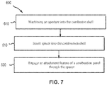
- the method includes inserting a spacer into a combustor shell, the spacer comprising a spacer aperture at least partially defined by an inner wall of the spacer.
- the method includes engaging an attachment feature of the combustor panel through the spacer aperture.
- the method may include engaging a nut on the attachment feature.
- the method includes machining a first aperture into the combustor shell.
- the method may include torqueing the nut.
- the inserting the spacer into the combustor shell comprises press fitting the spacer.
- any reference to attached, fixed, connected, or the like may include permanent, removable, temporary, partial, full, and/or any other possible attachment option.
- Surface shading lines may be used throughout the figures to denote different parts but not necessarily to denote the same or different materials. In some cases, reference coordinates may be specific to each figure.
- aft refers to the direction associated with the exhaust (e.g., the back end) of a gas turbine engine.
- forward refers to the direction associated with the intake (e.g., the front end) of a gas turbine engine.
- a first component that is “radially outward” of a second component means that the first component is positioned at a greater distance away from the engine central longitudinal axis than the second component.
- a first component that is “radially inward” of a second component means that the first component is positioned closer to the engine central longitudinal axis than the second component.
- a first component that is radially inward of a second component rotates through a circumferentially shorter path than the second component.
- the terminology “radially outward” and “radially inward” may also be used relative to references other than the engine central longitudinal axis.
- a first component of a combustor that is radially inward or radially outward of a second component of a combustor is positioned relative to the central longitudinal axis of the combustor.
- Gas turbine engine 20 may be a two-spool turbofan that generally incorporates a fan section 22, a compressor section 24, a combustor section 26 and a turbine section 28.
- Alternative engines may include, for example, an augmentor section among other systems or features.
- fan section 22 can drive coolant (e.g., air) along a bypass flow-path B while compressor section 24 can drive air along a core flow-path C for compression and communication into combustor section 26 then expansion through turbine section 28.
- coolant e.g., air
- compressor section 24 can drive air along a core flow-path C for compression and communication into combustor section 26 then expansion through turbine section 28.
- Gas turbine engine 20 may generally comprise a low speed spool 30 and a high speed spool 32 mounted for rotation about an engine central longitudinal axis A-A' relative to an engine static structure 36 or engine case via several bearing systems 38, 38-1, and 38-2.
- Engine central longitudinal axis A-A' is oriented in the z direction on the provided xyz axis. It should be understood that various bearing systems 38 at various locations may alternatively or additionally be provided, including for example, bearing system 38, bearing system 38-1, and bearing system 38-2.
- Low speed spool 30 may generally comprise an inner shaft 40 that interconnects a fan 42, a low pressure compressor 44 and a low pressure turbine 46.
- Inner shaft 40 may be connected to fan 42 through a geared architecture 48 that can drive fan 42 at a lower speed than low speed spool 30.
- Geared architecture 48 may comprise a gear assembly 60 enclosed within a gear housing 62.
- Gear assembly 60 couples inner shaft 40 to a rotating fan structure.
- High speed spool 32 may comprise an outer shaft 50 that interconnects a high pressure compressor 52 and high pressure turbine 54.
- a combustor 56 may be located between high pressure compressor 52 and high pressure turbine 54.
- the combustor section 26 may have an annular wall assembly having combustor outer shell 104 and a combustor inner shell 184 that support respective inner and outer heat shielding liners.
- Combustor outer shell 104 and combustor inner shell 184 may be hereafter referred to together as combustor shell 104, 184.
- the heat shield liners may include a plurality of combustor panels that collectively define the annular combustion chamber of the combustor 56.
- An annular cooling cavity is defined between the combustor shell 104, 184 and combustor panels for supplying cooling air. Impingement holes are located in the combustor shell 104, 184 to supply the cooling air from an outer air plenum and into the annular cooling cavity.
- a mid-turbine frame 57 of engine static structure 36 may be located generally between high pressure turbine 54 and low pressure turbine 46.
- Mid-turbine frame 57 may support one or more bearing systems 38 in turbine section 28.
- Inner shaft 40 and outer shaft 50 may be concentric and rotate via bearing systems 38 about the engine central longitudinal axis A-A', which is collinear with their longitudinal axes.
- a "high pressure" compressor or turbine experiences a higher pressure than a corresponding "low pressure” compressor or turbine.
- the core airflow C may be compressed by low pressure compressor 44 then high pressure compressor 52, mixed and burned with fuel in combustor 56, then expanded over high pressure turbine 54 and low pressure turbine 46.
- Turbines 46, 54 rotationally drive the respective low speed spool 30 and high speed spool 32 in response to the expansion.
- geared architecture 48 may be an epicyclic gear train, such as a star gear system (sun gear in meshing engagement with a plurality of star gears supported by a carrier and in meshing engagement with a ring gear) or other gear system.
- Geared architecture 48 may have a gear reduction ratio of greater than about 2.3 and low pressure turbine 46 may have a pressure ratio that is greater than about five (5).
- the bypass ratio of gas turbine engine 20 is greater than about ten (10:1).
- the diameter of fan 42 may be significantly larger than that of the low pressure compressor 44, and the low pressure turbine 46 may have a pressure ratio that is greater than about five (5:1).
- Low pressure turbine 46 pressure ratio may be measured prior to inlet of low pressure turbine 46 as related to the pressure at the outlet of low pressure turbine 46 prior to an exhaust nozzle. It should be understood, however, that the above parameters are exemplary of various embodiments of a suitable geared architecture engine and that the present disclosure contemplates other gas turbine engines including direct drive turbofans.
- a gas turbine engine may comprise an industrial gas turbine (IGT) or a geared aircraft engine, such as a geared turbofan, or non-geared aircraft engine, such as a turbofan, or may comprise any gas turbine engine as desired.
- IGT industrial gas turbine
- a geared aircraft engine such as a geared turbofan
- non-geared aircraft engine such as a turbofan
- one or more combustor panels 110 may be positioned in combustor 56 to protect various features of the combustor 56 from the high temperature flames and/or combustion gases.
- the combustor 56 in various embodiments, may have a combustor chamber 102 defined by a combustor outer shell 104 and a combustor inner shell 184.
- Combustor outer shell 104 and combustor inner shell 184 may be hereafter referred to together as combustor shell 104, 184.
- a diffuser chamber 101 is external the combustor 56 and cooling air may be configured to flow through the diffuser chamber 101 around the combustor 56.
- the combustor chamber 102 may form a region of mixing of core airflow C (with brief reference to FIG. 1 ) and fuel, and may direct the high-speed exhaust gases produced by the ignition of this mixture inside the combustor 56.
- Combustor shell 104, 184 may provide structural support to the combustor 56 and its components.
- combustor shell 104, 184 may comprise a substantially cylindrical or a substantially conical canister portion defining an inner area comprising the combustor chamber 102.
- one or more combustor panels 110 may be disposed inside the combustor chamber 102 and may provide such protection.
- the combustor panels 110 may comprise a partial cylindrical or conical surface section.
- An outer combustor thermal panel may be arranged radially inward of the combustor outer shell 104, for example, circumferentially about the inner surface of the combustor outer shell 104 and one or more inner combustor panels may also be arranged radially outward of the combustor inner shell 184.
- combustor shell 104, 184 may be outward of the combustor panel 110, and vice versa.
- the combustor panels 110 may comprise a variety of materials, such as metal, metal alloys, and/or ceramic matrix composites, among others.
- the combustor panels 110 may be mounted and/or coupled to the combustor shell 104, 184 via one or more attachment features 106.
- the combustor panels 110 may be made of any suitable heat tolerant material. In this manner, the combustor panels 110 may be substantially resistant to thermal mechanical fatigue in order to inhibit cracking of the combustor panels 110 and/or to inhibit liberation of portions of the combustor panels 110.
- the combustor panels 110 may be made from a nickel based alloy and/or a cobalt based alloy, among others.
- the combustor panels 110 may be made from a high performance nickel-based super alloy.
- the combustor panels 110 may be made from a cobalt-nickel-chromium-tungsten alloy.
- combustor shell 104, 184 may comprise a diffuser-facing side 141 and a combustor-facing side 142.
- Combustor shell 104, 184 may comprise first aperture 111 at least partially defined by the combustor shell 104, 184 and passing from diffuser-facing side 141 to combustor-facing side 142 of the combustor shell 104, 184.
- First aperture 111 may be at least partially bound by inner wall 149 of combustor shell 104, 184.
- First aperture 111 may be oval, obround, or another elongated shape (e.g., a slot) to provide clearance/tolerance during assembly/installation of the combustor panel 110.
- Combustor shell 104, 184 may comprise a plurality of first aperture 111.
- Combustor shell 104, 184 may comprise spacer 146.
- Spacer 146 may extend between diffuser-facing side 141 and combustor facing side 142 of combustor shell 104, 184.
- Spacer 146 may comprise spacer aperture 144 at least partially defined by inner wall 147 of spacer 146. Spacer aperture 144 may pass from diffuser-facing side 141 to combustor-facing side 142 of the combustor shell 104, 184.
- Outer wall 148 of spacer 146 may contact at least a portion of inner wall 149 of combustor shell 104, 184.
- the contact between outer wall 148 and inner wall 149 of combustor shell 104, 184 may reduce the friction force between the combustor shell 104 and the attachment feature 106.
- the tolerance fit between spacer 146 and combustor shell 104, 184 may set the friction force pre-load. At operating temperature, the friction force between the spacer 146 and combustor shell 104, 184 may be constant due the thermal expansion at the spacer 146.
- spacer 146 may be configured to receive attachment feature 106.
- Attachment feature 106 may extend through spacer aperture 144 of spacer 146. Spacer 146 may allow an application of torque on attachment feature 106 to keep the combustor panel 110 from becoming loose from the combustor shell 104, 184.
- Attachment features 106 may facilitate coupling and/or mounting the combustor panels 110 to the combustor shell 104, 184 of the combustor 56.
- attachment feature 106 may be a boss or a stud extending from the combustor panels 110.
- the attachment feature 106 may be a cylindrical boss, such as a pin with a threaded circumference, or may be a rectangular boss, such as for receiving a clip, or may be any other apparatus whereby the combustor panel 110 is mounted to the combustor shell 104, 184.
- the attachment feature 106 may be integrally formed with the combustor panel 110.
- the attachment feature 106 according to various embodiments and with reference to FIG. 3B , has a central longitudinal axis 125 and extends from the cold side 131 of the combustor panel 110.
- the attachment feature 106 may include a base portion 121 and a tip portion 122.
- the base portion 121 of the attachment feature 106 is generally defined, according to various embodiments, as the section of the attachment feature 106 disposed between the cold side 131 of the combustor panel 110 and the diffuser-facing side 141 of the combustor shell 104, 184.
- the tip portion 122 of the attachment feature 106 is generally defined, according to various embodiments, as the section of the attachment feature 106 disposed outward of the diffuser-facing side 141 of the combustor shell 104, 184.
- the terms “outward” and “inward,” without the modifier “radially”, refer to positions relative to the combustor chamber 102. That is, the combustor shell 104, 184 is outward of the combustor panel 110.
- the attachment feature 106 comprises a threaded stud that extends through spacer aperture 144 in the combustor shell 104, 184.
- the attachment feature 106 may be retained in position by a nut 152 disposed outward of the combustor shell 104, 184 and engaged onto the attachment feature and torqued so that the attachment feature 106 is preloaded with a retaining force and securely affixes the combustor panel 110 in a substantially fixed position relative to the combustor shell 104, 184.
- the combustor panel 110 includes a plurality of standoffs 112 extending from the cold side 131 of the combustor panel 110 that are circumferentially distributed around the base portion 121 of the attachment feature 106.
- the standoffs 112 sustain a distance between the combustor panel 110 and the combustor shell 104, 184 and prevent the combustor attachment feature 106 from being overloaded with a retaining force that would drive the combustor panel 110 and the combustor shell 104, 184 too close together.
- a washer 154 may be disposed between the nut 152 and the diffuser-facing side 141 of the combustor shell 104, 184.
- annular cooling cavity 117 is formed and/or defined between the combustor shell 104, 184 and the combustor panel 110.
- cooling air in the diffuser chamber 101 may enter the annular cooling cavity 117 via impingement holes 105 formed in the combustor shell 104, 184. That is, impingement holes 105 may extend from a diffuser-facing side 141 of the combustor shell 104, 184 to a combustor-facing side 142 of the combustor shell 104, 184 and may supply cooling air to the annular cooling cavity 117.
- the cooling air in the annular cooling cavity 117 may enter the combustor chamber 102 via effusion holes 107 formed in the combustor panel.
- effusion holes 107 may extend from a cooling surface or "cold side” 131 of the combustor panel to a combustion facing surface or "hot side” 132 of the combustor panel that is opposite the cold side 131.
- the effusion holes 107 are generally oriented to create a protective "blanket” of air film over the hot side 132 of the combustor panel thereby protecting the combustor panel from the hot combustion gases in the combustor chamber 102.
- engagement length A is the length of contact between attachment feature 106 and inner wall 147 of spacer 146.
- Spacer 146 may also have diameter D.
- spacer 146 and attachment feature 106 may be made from metallic materials selected to exhibit favorable wear characteristics.
- spacer 146 may be made from a cobalt-chromium alloy having favorable wear characteristics (e.g., one of the alloys available under the trademark STELLITE).
- Spacer 146 may be made, for example, by the machining process known as turning.
- Spacer 146 may comprise a bushing.
- spacer 146 may be integrally formed with combustor shell 104, 184. Spacer 146 may be press fit into combustor shell 104, 184.
- combustor shell 104, 184 comprises spcer.
- Spacer 246 extends between diffuser-facing side 141 and combustor facing side 142 of combustor shell 104, 184.
- Spacer 246 may comprise spacer aperture 244 at least partially defined by inner wall 247 of spacer 246. Spacer aperture 244 may pass from diffuser-facing side 141 to combustor-facing side 142 of the combustor shell 104, 184.
- Outer wall 248 of spacer 246 contacts at least a portion of inner wall 149 of combustor shell 104, 184.
- Spacer 246 comprises a first flange 260.
- First flange 260 is disposed on and along the diffuser-facing 141 side of the combustor shell 104, 184.
- Spacer 246 comprises a first segment 265 disposed between inner wall 247 and outer wall 248.
- spacer 246 may comprise second flange 270.
- Second flange 270 may be disposed on and along the combustor-facing 142 side of the combustor shell 104, 184.
- First segment 265 may be disposed between the first flange 260 and second flange 270.
- Engagement length A' is the length of contact between attachment feature 106 and inner wall 247 of spacer 246.
- Length B is the length between diffuser-facing side 141 and combustor facing side 142 of combustor shell 104, 184. Length B may correspond to the length of the first segment 265. Spacer 246 may also have width C wherein spacer 246 extends radially outward of outer wall 248 along diffuser-facing side 141 and combustor facing side 142 of combustor shell 104, 184. Width C may correspond to the width of one or both first flange 260 and second flange 270. In various embodiments, length A' may be greater than length B.
- a washer 154 may be disposed between the nut 152 and first flange 260 of spacer 246.
- the standoffs 112 may contact second flange 270 of spacer 246.
- Spacer 246 may comprise a bushing.
- combustor shell 104, 184 comprises spacer 346.
- Spacer 346 extends between diffuser-facing side 141 and combustor facing side 142 of combustor shell 104, 184.
- Spacer 346 may comprise spacer aperture 344 at least partially defined by inner wall 347 of spacer 346. Spacer aperture 344 may pass from diffuser-facing side 141 to combustor-facing side 142 of the combustor shell 104, 184.
- Outer wall 348 of spacer 346 contacts at least a portion of inner wall 149 of combustor shell 104, 184 According to the invention, spacer 346 comprises a first flange 360.
- First flange 360 is disposed on and along the diffuser-facing 141 side of the combustor shell 104,184.
- Spacer 346 comprises a first segment 365 disposed between inner wall 347 and outer wall 348.
- spacer 346 may comprise second flange 370.
- Second flange 370 may be disposed on and along the combustor-facing 142 side of the combustor shell 104, 184.
- First segment 365 may be disposed between the first flange 360 and second flange 370.
- Spacer 346 may comprise threads 350 on an inner wall 347 which may mate with threads 354 along attachment feature 106.
- a washer 154 may be disposed between the nut 152 and first flange 360 of spacer 346.
- the standoffs 112 may contact second flange 370 of spacer 346.
- Spacer 346 may comprise a bushing.
- a method 500 of mounting a combustor panel to a combustor shell is illustrated.
- a spacer is inserting into a combustor shell (step 510).
- the spacer comprises a spacer aperture at least partially defined by an inner wall of the spacer.
- An attachment feature of a combustion panel is engaged through the spacer aperture (step 520).
- a nut is engaged on the attachment feature (step 530).
- a method 600 of mounting a combustor panel to a combustor shell still according to the invention further includes machining a first aperture into the combustor shell (step 610).
- a method 700 of mounting a combustor panel to a combustor shell may further include torqueing the nut (step 710).
Landscapes
- Engineering & Computer Science (AREA)
- General Engineering & Computer Science (AREA)
- Mechanical Engineering (AREA)
- Chemical & Material Sciences (AREA)
- Combustion & Propulsion (AREA)
- Turbine Rotor Nozzle Sealing (AREA)
- Connection Of Plates (AREA)
Claims (11)
- Enveloppe de chambre de combustion (104, 184) comprenant :une première ouverture (111) au moins partiellement définie par une paroi intérieure (149) de l'enveloppe de chambre de combustion (104, 184) et passant d'un côté faisant face au diffuseur (141) de l'enveloppe de chambre de combustion (104, 184) à un côté faisant face à une chambre de combustion (142) de l'enveloppe de chambre de combustion (104, 184) ; etune entretoise (146, 246, 346) comprenant un premier segment (265, 365) couplé à une première bride (260, 360), dans laquelle la première bride (260, 360) est disposée sur le côté faisant face au diffuseur (141) de l'enveloppe de chambre de combustion,dans laquelle une paroi externe (148, 248, 348) de l'entretoise (146, 246) est couplée à au moins une partie de la paroi interne (149) de l'enveloppe de chambre de combustion (104, 184) ;caractérisée en ce que :la première ouverture (111) de l'enveloppe de chambre de combustion (104, 184) est de forme oblongue ; etun contact entre la paroi extérieure (148, 248, 348) de l'entretoise (146, 246) et la paroi intérieure (149) de l'enveloppe de chambre de combustion (104, 184) est conçue pour réduire une force de frottement entre l'enveloppe de chambre de combustion (104, 184) etun élément de fixation (106) disposé à travers l'entretoise (146, 246, 346) .
- Enveloppe de chambre de combustion (104, 184) selon la revendication 1, dans laquelle l'entretoise (346) comprend des filetages (350) sur une paroi intérieure (347) de l'entretoise (346) .
- Enveloppe de chambre de combustion (104, 184) selon la revendication 1 ou 2, dans laquelle l'entretoise (146) fait l'objet d'un ajustement serré dans l'enveloppe de chambre de combustion (104, 184).
- Enveloppe de chambre de combustion (104, 184) selon une quelconque revendication précédente, dans laquelle l'entretoise (146) est conçue pour venir en prise avec un élément de fixation (106) d'un panneau de chambre de combustion (110).
- Enveloppe de chambre de combustion (104, 184) selon la revendication 4, dans laquelle une longueur de contact entre l'entretoise (146) et l'élément de fixation (106) est supérieure à une distance entre le côté faisant face au diffuseur (141) de l'enveloppe de chambre de combustion (104, 184) et le côté faisant face à la chambre de combustion (142) de l'enveloppe de chambre de combustion (104, 184).
- Enveloppe de chambre de combustion (104, 184) selon une quelconque revendication précédente, dans laquelle l'entretoise (246, 346) comprend en outre une seconde bride (270, 370) couplée au premier segment (265, 365) et disposée du côté faisant face à la chambre de combustion (142) de l'enveloppe de la chambre de combustion (104, 184).
- Enveloppe de chambre de combustion (104, 184) selon une quelconque revendication précédente, dans laquelle l'entretoise (146, 246, 346) comprend en outre une ouverture d'entretoise (144, 244, 344) au moins partiellement définie par une paroi intérieure (147, 247, 347) de l'entretoise (146, 246, 346).
- Moteur à turbine à gaz (20) comprenant,
une chambre de combustion (26), la chambre de combustion (26) comprenant une enveloppe de chambre de combustion (104, 184) selon une quelconque revendication précédente. - Procédé de montage d'un panneau de chambre de combustion (110) sur une enveloppe de chambre de combustion (104, 184), comprenant :l'usinage d'une première ouverture de forme oblongue (111) dans l'enveloppe de chambre de combustion (104, 184) ;l'insertion d'une entretoise (146, 246, 346) dans la première ouverture (111) de l'enveloppe de chambre de combustion (104, 184), l'entretoise (146, 246, 346) comprenant une ouverture d'entretoise (144, 244, 344) au moins partiellement définie par une paroi intérieure (147, 247, 347) de l'entretoise (146, 246, 346) ;la mise en prise d'un élément de fixation (106) du panneau de chambre de combustion (110) à travers l'ouverture d'entretoise (144, 244, 344) ; etla mise en prise d'un écrou sur l'élément de fixation (106) de telle sorte qu'un contact entre une paroi extérieure (148, 248, 348) de l'entretoise (146, 246) et une paroi intérieure (149) de l'enveloppe de chambre de combustion (104, 184) réduit une force de frottement entre l'enveloppe de chambre de combustion (104, 184) et l'élément de fixation (106).
- Procédé selon la revendication 9, comprenant en outre le serrage de l'écrou.
- Procédé selon la revendication 9 ou 10, dans lequel l'insertion de l'entretoise dans l'enveloppe de la chambre de combustion comprend l'ajustement serré de l'entretoise.
Applications Claiming Priority (1)
| Application Number | Priority Date | Filing Date | Title |
|---|---|---|---|
| US16/022,080 US10808930B2 (en) | 2018-06-28 | 2018-06-28 | Combustor shell attachment |
Publications (2)
| Publication Number | Publication Date |
|---|---|
| EP3587928A1 EP3587928A1 (fr) | 2020-01-01 |
| EP3587928B1 true EP3587928B1 (fr) | 2021-12-29 |
Family
ID=67137608
Family Applications (1)
| Application Number | Title | Priority Date | Filing Date |
|---|---|---|---|
| EP19183202.1A Active EP3587928B1 (fr) | 2018-06-28 | 2019-06-28 | Coque de chambre de combustion |
Country Status (2)
| Country | Link |
|---|---|
| US (1) | US10808930B2 (fr) |
| EP (1) | EP3587928B1 (fr) |
Families Citing this family (11)
| Publication number | Priority date | Publication date | Assignee | Title |
|---|---|---|---|---|
| US11512730B2 (en) * | 2020-05-15 | 2022-11-29 | Gm Cruise Holdings Llc | Stud assembly for high current applications |
| CN116928695A (zh) | 2022-03-31 | 2023-10-24 | 通用电气公司 | 用于燃烧器的环形圆顶组件 |
| CN116928696A (zh) | 2022-03-31 | 2023-10-24 | 通用电气公司 | 用于燃烧器的衬套组件 |
| CN117091158B (zh) * | 2022-05-13 | 2026-03-06 | 通用电气公司 | 燃烧器室网状结构 |
| CN117091159A (zh) | 2022-05-13 | 2023-11-21 | 通用电气公司 | 燃烧器衬里 |
| CN117091161A (zh) | 2022-05-13 | 2023-11-21 | 通用电气公司 | 燃烧器衬里的中空板设计和结构 |
| CN117091157A (zh) | 2022-05-13 | 2023-11-21 | 通用电气公司 | 用于耐用燃烧室衬里的板吊架结构 |
| CN117091162B (zh) | 2022-05-13 | 2026-03-27 | 通用电气公司 | 具有稀释孔结构的燃烧器 |
| CN117917530A (zh) | 2022-10-20 | 2024-04-23 | 通用电气公司 | 用于涡轮发动机的联接组件 |
| US12270545B1 (en) * | 2024-05-20 | 2025-04-08 | Rtx Corporation | T-head bolts or hollow flanged bushing with one thread or grooved end in a multi-liner arrangement |
| US12474052B1 (en) | 2024-05-20 | 2025-11-18 | Rtx Corporation | Dovetail features on panel rails or impingement sheet to hold panels |
Family Cites Families (12)
| Publication number | Priority date | Publication date | Assignee | Title |
|---|---|---|---|---|
| US3545202A (en) * | 1969-04-02 | 1970-12-08 | United Aircraft Corp | Wall structure and combustion holes for a gas turbine engine |
| FR2599821B1 (fr) * | 1986-06-04 | 1988-09-02 | Snecma | Chambre de combustion pour turbomachines a orifices de melange assurant le positionnement de la paroi chaude sur la paroi froide |
| US4944151A (en) | 1988-09-26 | 1990-07-31 | Avco Corporation | Segmented combustor panel |
| US5369952A (en) | 1993-07-20 | 1994-12-06 | General Electric Company | Variable friction force damper |
| US5415000A (en) * | 1994-06-13 | 1995-05-16 | Westinghouse Electric Corporation | Low NOx combustor retro-fit system for gas turbines |
| US6619915B1 (en) | 2002-08-06 | 2003-09-16 | Power Systems Mfg, Llc | Thermally free aft frame for a transition duct |
| US8800298B2 (en) * | 2009-07-17 | 2014-08-12 | United Technologies Corporation | Washer with cooling passage for a turbine engine combustor |
| US9010123B2 (en) * | 2010-07-26 | 2015-04-21 | Honeywell International Inc. | Combustors with quench inserts |
| DE102012023297A1 (de) * | 2012-11-28 | 2014-06-12 | Rolls-Royce Deutschland Ltd & Co Kg | Schindelbefestigungsanordnung einer Gasturbinenbrennkammer |
| GB201222311D0 (en) | 2012-12-12 | 2013-01-23 | Rolls Royce Plc | A combusiton chamber |
| WO2014107437A1 (fr) * | 2013-01-02 | 2014-07-10 | Illinois Tool Works Inc. | Ensemble de connexion d'œillet à rotation sur place |
| DE102015225107A1 (de) | 2015-12-14 | 2017-06-14 | Rolls-Royce Deutschland Ltd & Co Kg | Gasturbinenbrennkammer mit Schindelbefestigung mittels Rastelementen |
-
2018
- 2018-06-28 US US16/022,080 patent/US10808930B2/en active Active
-
2019
- 2019-06-28 EP EP19183202.1A patent/EP3587928B1/fr active Active
Also Published As
| Publication number | Publication date |
|---|---|
| US20200003417A1 (en) | 2020-01-02 |
| US10808930B2 (en) | 2020-10-20 |
| EP3587928A1 (fr) | 2020-01-01 |
Similar Documents
| Publication | Publication Date | Title |
|---|---|---|
| EP3587928B1 (fr) | Coque de chambre de combustion | |
| EP3404329B1 (fr) | Interface de rail inférieur de panneau de combustion | |
| EP3453965B1 (fr) | Configuration de refroidissement pour caractéristique de fixation de chambre de combustion | |
| EP3404330B1 (fr) | Rail d'extrémité redondant pour panneau de chambre de combustion | |
| EP3453967B1 (fr) | Panneau de chambre de combustion avec configuration de refroidissement pour élément de fixation dudit panneau | |
| EP3244028B1 (fr) | Mécanisme de rétention de fixation | |
| EP3453968B1 (fr) | Configurations de refroidissement pour caractéristiques de fixation de chambre de combustion | |
| EP3232018B1 (fr) | Bouclier thermique avec verrou de retenue axiale | |
| EP3330612A1 (fr) | Systèmes et procédés pour chambre de combustion | |
| EP3042060B1 (fr) | Moteur de turbine à gaz comprenant une chambre de combustion munie d'un écran thermique | |
| EP3453966B1 (fr) | Panneau de chambre de combustion | |
| US12038175B2 (en) | Extended bulkhead panel | |
| EP3232019B1 (fr) | Bouclier thermique ayant un verrou de retenue axiale | |
| EP3453969B1 (fr) | Panneaux de chambre de combustion avec des caractéristiques de fixation | |
| US11175041B2 (en) | Systems and methods for combustor panel | |
| EP3382278A1 (fr) | Broches de transfert de chaleur de panneau de chambre de combustion avec des caractéristiques géométriques variables et procédé de manufacture du panneau | |
| EP3677836A1 (fr) | Refroidissement de goujon de panneau de chambre de combustion par dispositif d'effusion au travers d'augmenteurs de transfert de chaleur |
Legal Events
| Date | Code | Title | Description |
|---|---|---|---|
| PUAI | Public reference made under article 153(3) epc to a published international application that has entered the european phase |
Free format text: ORIGINAL CODE: 0009012 |
|
| STAA | Information on the status of an ep patent application or granted ep patent |
Free format text: STATUS: THE APPLICATION HAS BEEN PUBLISHED |
|
| AK | Designated contracting states |
Kind code of ref document: A1 Designated state(s): AL AT BE BG CH CY CZ DE DK EE ES FI FR GB GR HR HU IE IS IT LI LT LU LV MC MK MT NL NO PL PT RO RS SE SI SK SM TR |
|
| AX | Request for extension of the european patent |
Extension state: BA ME |
|
| STAA | Information on the status of an ep patent application or granted ep patent |
Free format text: STATUS: REQUEST FOR EXAMINATION WAS MADE |
|
| 17P | Request for examination filed |
Effective date: 20200701 |
|
| RBV | Designated contracting states (corrected) |
Designated state(s): AL AT BE BG CH CY CZ DE DK EE ES FI FR GB GR HR HU IE IS IT LI LT LU LV MC MK MT NL NO PL PT RO RS SE SI SK SM TR |
|
| GRAP | Despatch of communication of intention to grant a patent |
Free format text: ORIGINAL CODE: EPIDOSNIGR1 |
|
| STAA | Information on the status of an ep patent application or granted ep patent |
Free format text: STATUS: GRANT OF PATENT IS INTENDED |
|
| INTG | Intention to grant announced |
Effective date: 20210125 |
|
| RAP1 | Party data changed (applicant data changed or rights of an application transferred) |
Owner name: RAYTHEON TECHNOLOGIES CORPORATION |
|
| GRAJ | Information related to disapproval of communication of intention to grant by the applicant or resumption of examination proceedings by the epo deleted |
Free format text: ORIGINAL CODE: EPIDOSDIGR1 |
|
| STAA | Information on the status of an ep patent application or granted ep patent |
Free format text: STATUS: REQUEST FOR EXAMINATION WAS MADE |
|
| INTC | Intention to grant announced (deleted) | ||
| GRAP | Despatch of communication of intention to grant a patent |
Free format text: ORIGINAL CODE: EPIDOSNIGR1 |
|
| STAA | Information on the status of an ep patent application or granted ep patent |
Free format text: STATUS: GRANT OF PATENT IS INTENDED |
|
| INTG | Intention to grant announced |
Effective date: 20210811 |
|
| GRAS | Grant fee paid |
Free format text: ORIGINAL CODE: EPIDOSNIGR3 |
|
| GRAA | (expected) grant |
Free format text: ORIGINAL CODE: 0009210 |
|
| STAA | Information on the status of an ep patent application or granted ep patent |
Free format text: STATUS: THE PATENT HAS BEEN GRANTED |
|
| AK | Designated contracting states |
Kind code of ref document: B1 Designated state(s): AL AT BE BG CH CY CZ DE DK EE ES FI FR GB GR HR HU IE IS IT LI LT LU LV MC MK MT NL NO PL PT RO RS SE SI SK SM TR |
|
| REG | Reference to a national code |
Ref country code: GB Ref legal event code: FG4D |
|
| REG | Reference to a national code |
Ref country code: CH Ref legal event code: EP |
|
| REG | Reference to a national code |
Ref country code: DE Ref legal event code: R096 Ref document number: 602019010381 Country of ref document: DE |
|
| REG | Reference to a national code |
Ref country code: AT Ref legal event code: REF Ref document number: 1458957 Country of ref document: AT Kind code of ref document: T Effective date: 20220115 |
|
| REG | Reference to a national code |
Ref country code: IE Ref legal event code: FG4D |
|
| REG | Reference to a national code |
Ref country code: LT Ref legal event code: MG9D |
|
| PG25 | Lapsed in a contracting state [announced via postgrant information from national office to epo] |
Ref country code: RS Free format text: LAPSE BECAUSE OF FAILURE TO SUBMIT A TRANSLATION OF THE DESCRIPTION OR TO PAY THE FEE WITHIN THE PRESCRIBED TIME-LIMIT Effective date: 20211229 Ref country code: LT Free format text: LAPSE BECAUSE OF FAILURE TO SUBMIT A TRANSLATION OF THE DESCRIPTION OR TO PAY THE FEE WITHIN THE PRESCRIBED TIME-LIMIT Effective date: 20211229 Ref country code: FI Free format text: LAPSE BECAUSE OF FAILURE TO SUBMIT A TRANSLATION OF THE DESCRIPTION OR TO PAY THE FEE WITHIN THE PRESCRIBED TIME-LIMIT Effective date: 20211229 Ref country code: BG Free format text: LAPSE BECAUSE OF FAILURE TO SUBMIT A TRANSLATION OF THE DESCRIPTION OR TO PAY THE FEE WITHIN THE PRESCRIBED TIME-LIMIT Effective date: 20220329 |
|
| REG | Reference to a national code |
Ref country code: NL Ref legal event code: MP Effective date: 20211229 |
|
| REG | Reference to a national code |
Ref country code: AT Ref legal event code: MK05 Ref document number: 1458957 Country of ref document: AT Kind code of ref document: T Effective date: 20211229 |
|
| PG25 | Lapsed in a contracting state [announced via postgrant information from national office to epo] |
Ref country code: SE Free format text: LAPSE BECAUSE OF FAILURE TO SUBMIT A TRANSLATION OF THE DESCRIPTION OR TO PAY THE FEE WITHIN THE PRESCRIBED TIME-LIMIT Effective date: 20211229 Ref country code: NO Free format text: LAPSE BECAUSE OF FAILURE TO SUBMIT A TRANSLATION OF THE DESCRIPTION OR TO PAY THE FEE WITHIN THE PRESCRIBED TIME-LIMIT Effective date: 20220329 Ref country code: LV Free format text: LAPSE BECAUSE OF FAILURE TO SUBMIT A TRANSLATION OF THE DESCRIPTION OR TO PAY THE FEE WITHIN THE PRESCRIBED TIME-LIMIT Effective date: 20211229 Ref country code: HR Free format text: LAPSE BECAUSE OF FAILURE TO SUBMIT A TRANSLATION OF THE DESCRIPTION OR TO PAY THE FEE WITHIN THE PRESCRIBED TIME-LIMIT Effective date: 20211229 Ref country code: GR Free format text: LAPSE BECAUSE OF FAILURE TO SUBMIT A TRANSLATION OF THE DESCRIPTION OR TO PAY THE FEE WITHIN THE PRESCRIBED TIME-LIMIT Effective date: 20220330 |
|
| PG25 | Lapsed in a contracting state [announced via postgrant information from national office to epo] |
Ref country code: NL Free format text: LAPSE BECAUSE OF FAILURE TO SUBMIT A TRANSLATION OF THE DESCRIPTION OR TO PAY THE FEE WITHIN THE PRESCRIBED TIME-LIMIT Effective date: 20211229 |
|
| PG25 | Lapsed in a contracting state [announced via postgrant information from national office to epo] |
Ref country code: SM Free format text: LAPSE BECAUSE OF FAILURE TO SUBMIT A TRANSLATION OF THE DESCRIPTION OR TO PAY THE FEE WITHIN THE PRESCRIBED TIME-LIMIT Effective date: 20211229 Ref country code: SK Free format text: LAPSE BECAUSE OF FAILURE TO SUBMIT A TRANSLATION OF THE DESCRIPTION OR TO PAY THE FEE WITHIN THE PRESCRIBED TIME-LIMIT Effective date: 20211229 Ref country code: RO Free format text: LAPSE BECAUSE OF FAILURE TO SUBMIT A TRANSLATION OF THE DESCRIPTION OR TO PAY THE FEE WITHIN THE PRESCRIBED TIME-LIMIT Effective date: 20211229 Ref country code: PT Free format text: LAPSE BECAUSE OF FAILURE TO SUBMIT A TRANSLATION OF THE DESCRIPTION OR TO PAY THE FEE WITHIN THE PRESCRIBED TIME-LIMIT Effective date: 20220429 Ref country code: ES Free format text: LAPSE BECAUSE OF FAILURE TO SUBMIT A TRANSLATION OF THE DESCRIPTION OR TO PAY THE FEE WITHIN THE PRESCRIBED TIME-LIMIT Effective date: 20211229 Ref country code: EE Free format text: LAPSE BECAUSE OF FAILURE TO SUBMIT A TRANSLATION OF THE DESCRIPTION OR TO PAY THE FEE WITHIN THE PRESCRIBED TIME-LIMIT Effective date: 20211229 Ref country code: CZ Free format text: LAPSE BECAUSE OF FAILURE TO SUBMIT A TRANSLATION OF THE DESCRIPTION OR TO PAY THE FEE WITHIN THE PRESCRIBED TIME-LIMIT Effective date: 20211229 |
|
| PG25 | Lapsed in a contracting state [announced via postgrant information from national office to epo] |
Ref country code: PL Free format text: LAPSE BECAUSE OF FAILURE TO SUBMIT A TRANSLATION OF THE DESCRIPTION OR TO PAY THE FEE WITHIN THE PRESCRIBED TIME-LIMIT Effective date: 20211229 Ref country code: AT Free format text: LAPSE BECAUSE OF FAILURE TO SUBMIT A TRANSLATION OF THE DESCRIPTION OR TO PAY THE FEE WITHIN THE PRESCRIBED TIME-LIMIT Effective date: 20211229 |
|
| PG25 | Lapsed in a contracting state [announced via postgrant information from national office to epo] |
Ref country code: IS Free format text: LAPSE BECAUSE OF FAILURE TO SUBMIT A TRANSLATION OF THE DESCRIPTION OR TO PAY THE FEE WITHIN THE PRESCRIBED TIME-LIMIT Effective date: 20220429 |
|
| REG | Reference to a national code |
Ref country code: DE Ref legal event code: R097 Ref document number: 602019010381 Country of ref document: DE |
|
| PG25 | Lapsed in a contracting state [announced via postgrant information from national office to epo] |
Ref country code: DK Free format text: LAPSE BECAUSE OF FAILURE TO SUBMIT A TRANSLATION OF THE DESCRIPTION OR TO PAY THE FEE WITHIN THE PRESCRIBED TIME-LIMIT Effective date: 20211229 Ref country code: AL Free format text: LAPSE BECAUSE OF FAILURE TO SUBMIT A TRANSLATION OF THE DESCRIPTION OR TO PAY THE FEE WITHIN THE PRESCRIBED TIME-LIMIT Effective date: 20211229 |
|
| PLBE | No opposition filed within time limit |
Free format text: ORIGINAL CODE: 0009261 |
|
| STAA | Information on the status of an ep patent application or granted ep patent |
Free format text: STATUS: NO OPPOSITION FILED WITHIN TIME LIMIT |
|
| 26N | No opposition filed |
Effective date: 20220930 |
|
| PG25 | Lapsed in a contracting state [announced via postgrant information from national office to epo] |
Ref country code: MC Free format text: LAPSE BECAUSE OF FAILURE TO SUBMIT A TRANSLATION OF THE DESCRIPTION OR TO PAY THE FEE WITHIN THE PRESCRIBED TIME-LIMIT Effective date: 20211229 |
|
| REG | Reference to a national code |
Ref country code: CH Ref legal event code: PL |
|
| REG | Reference to a national code |
Ref country code: BE Ref legal event code: MM Effective date: 20220630 |
|
| PG25 | Lapsed in a contracting state [announced via postgrant information from national office to epo] |
Ref country code: SI Free format text: LAPSE BECAUSE OF FAILURE TO SUBMIT A TRANSLATION OF THE DESCRIPTION OR TO PAY THE FEE WITHIN THE PRESCRIBED TIME-LIMIT Effective date: 20211229 |
|
| PG25 | Lapsed in a contracting state [announced via postgrant information from national office to epo] |
Ref country code: LU Free format text: LAPSE BECAUSE OF NON-PAYMENT OF DUE FEES Effective date: 20220628 Ref country code: LI Free format text: LAPSE BECAUSE OF NON-PAYMENT OF DUE FEES Effective date: 20220630 Ref country code: IE Free format text: LAPSE BECAUSE OF NON-PAYMENT OF DUE FEES Effective date: 20220628 Ref country code: CH Free format text: LAPSE BECAUSE OF NON-PAYMENT OF DUE FEES Effective date: 20220630 |
|
| PG25 | Lapsed in a contracting state [announced via postgrant information from national office to epo] |
Ref country code: IT Free format text: LAPSE BECAUSE OF FAILURE TO SUBMIT A TRANSLATION OF THE DESCRIPTION OR TO PAY THE FEE WITHIN THE PRESCRIBED TIME-LIMIT Effective date: 20211229 Ref country code: BE Free format text: LAPSE BECAUSE OF NON-PAYMENT OF DUE FEES Effective date: 20220630 |
|
| P01 | Opt-out of the competence of the unified patent court (upc) registered |
Effective date: 20230521 |
|
| PG25 | Lapsed in a contracting state [announced via postgrant information from national office to epo] |
Ref country code: MK Free format text: LAPSE BECAUSE OF FAILURE TO SUBMIT A TRANSLATION OF THE DESCRIPTION OR TO PAY THE FEE WITHIN THE PRESCRIBED TIME-LIMIT Effective date: 20211229 Ref country code: CY Free format text: LAPSE BECAUSE OF FAILURE TO SUBMIT A TRANSLATION OF THE DESCRIPTION OR TO PAY THE FEE WITHIN THE PRESCRIBED TIME-LIMIT Effective date: 20211229 |
|
| PG25 | Lapsed in a contracting state [announced via postgrant information from national office to epo] |
Ref country code: HU Free format text: LAPSE BECAUSE OF FAILURE TO SUBMIT A TRANSLATION OF THE DESCRIPTION OR TO PAY THE FEE WITHIN THE PRESCRIBED TIME-LIMIT; INVALID AB INITIO Effective date: 20190628 |
|
| PG25 | Lapsed in a contracting state [announced via postgrant information from national office to epo] |
Ref country code: MT Free format text: LAPSE BECAUSE OF FAILURE TO SUBMIT A TRANSLATION OF THE DESCRIPTION OR TO PAY THE FEE WITHIN THE PRESCRIBED TIME-LIMIT Effective date: 20211229 |
|
| PGFP | Annual fee paid to national office [announced via postgrant information from national office to epo] |
Ref country code: DE Payment date: 20250520 Year of fee payment: 7 |
|
| PGFP | Annual fee paid to national office [announced via postgrant information from national office to epo] |
Ref country code: GB Payment date: 20250520 Year of fee payment: 7 |
|
| PGFP | Annual fee paid to national office [announced via postgrant information from national office to epo] |
Ref country code: FR Payment date: 20250520 Year of fee payment: 7 |
|
| REG | Reference to a national code |
Ref country code: DE Ref legal event code: R081 Ref document number: 602019010381 Country of ref document: DE Owner name: RTX CORPORATION (N.D.GES.D. STAATES DELAWARE),, US Free format text: FORMER OWNER: RAYTHEON TECHNOLOGIES CORPORATION, FARMINGTON, CT, US |
|
| PG25 | Lapsed in a contracting state [announced via postgrant information from national office to epo] |
Ref country code: TR Free format text: LAPSE BECAUSE OF FAILURE TO SUBMIT A TRANSLATION OF THE DESCRIPTION OR TO PAY THE FEE WITHIN THE PRESCRIBED TIME-LIMIT Effective date: 20211229 |