EP3587998B1 - Dispositif et procédé de mesure optique d'un boudin de produit de l'industrie de traitement du tabac et utilisation d'un dispositif de mesure optique - Google Patents
Dispositif et procédé de mesure optique d'un boudin de produit de l'industrie de traitement du tabac et utilisation d'un dispositif de mesure optique Download PDFInfo
- Publication number
- EP3587998B1 EP3587998B1 EP19178947.8A EP19178947A EP3587998B1 EP 3587998 B1 EP3587998 B1 EP 3587998B1 EP 19178947 A EP19178947 A EP 19178947A EP 3587998 B1 EP3587998 B1 EP 3587998B1
- Authority
- EP
- European Patent Office
- Prior art keywords
- light
- measuring device
- optical measuring
- rod
- product
- Prior art date
- Legal status (The legal status is an assumption and is not a legal conclusion. Google has not performed a legal analysis and makes no representation as to the accuracy of the status listed.)
- Active
Links
Images


Classifications
-
- G—PHYSICS
- G01—MEASURING; TESTING
- G01B—MEASURING LENGTH, THICKNESS OR SIMILAR LINEAR DIMENSIONS; MEASURING ANGLES; MEASURING AREAS; MEASURING IRREGULARITIES OF SURFACES OR CONTOURS
- G01B11/00—Measuring arrangements characterised by the use of optical techniques
- G01B11/24—Measuring arrangements characterised by the use of optical techniques for measuring contours or curvatures
- G01B11/245—Measuring arrangements characterised by the use of optical techniques for measuring contours or curvatures using a plurality of fixed, simultaneously operating transducers
-
- G—PHYSICS
- G01—MEASURING; TESTING
- G01N—INVESTIGATING OR ANALYSING MATERIALS BY DETERMINING THEIR CHEMICAL OR PHYSICAL PROPERTIES
- G01N21/00—Investigating or analysing materials by the use of optical means, i.e. using sub-millimetre waves, infrared, visible or ultraviolet light
- G01N21/84—Systems specially adapted for particular applications
- G01N21/88—Investigating the presence of flaws or contamination
- G01N21/95—Investigating the presence of flaws or contamination characterised by the material or shape of the object to be examined
- G01N21/952—Inspecting the exterior surface of cylindrical bodies or wires
-
- A—HUMAN NECESSITIES
- A24—TOBACCO; CIGARS; CIGARETTES; SIMULATED SMOKING DEVICES; SMOKERS' REQUISITES
- A24C—MACHINES FOR MAKING CIGARS OR CIGARETTES
- A24C5/00—Making cigarettes; Making tipping materials for, or attaching filters or mouthpieces to, cigars or cigarettes
- A24C5/32—Separating, ordering, counting or examining cigarettes; Regulating the feeding of tobacco according to rod or cigarette condition
- A24C5/34—Examining cigarettes or the rod, e.g. for regulating the feeding of tobacco; Removing defective cigarettes
- A24C5/3412—Examining cigarettes or the rod, e.g. for regulating the feeding of tobacco; Removing defective cigarettes by means of light, radiation or electrostatic fields
-
- G—PHYSICS
- G01—MEASURING; TESTING
- G01B—MEASURING LENGTH, THICKNESS OR SIMILAR LINEAR DIMENSIONS; MEASURING ANGLES; MEASURING AREAS; MEASURING IRREGULARITIES OF SURFACES OR CONTOURS
- G01B11/00—Measuring arrangements characterised by the use of optical techniques
- G01B11/08—Measuring arrangements characterised by the use of optical techniques for measuring diameters
- G01B11/10—Measuring arrangements characterised by the use of optical techniques for measuring diameters of objects while moving
- G01B11/105—Measuring arrangements characterised by the use of optical techniques for measuring diameters of objects while moving using photoelectric detection means
Definitions
- the present invention relates to an optical measuring device for determining at least one feature, quality value and / or service data of an endlessly processed product strand of the tobacco processing industry on the basis of triangulation, comprising at least one light source for generating a plurality of incident beam paths that surround the circumference of the The product strand falls on its surface, at least three light-sensitive elements that are arranged in a triangulation arrangement relative to the incident beam paths, and a digital evaluation device that is set up to determine a 3-dimensional surface profile of the product strand from the measurement signals transmitted by the light-sensitive elements.
- the invention also relates to the use of such an optical measuring device and a corresponding optical measuring method.
- an optical measuring device based on the shadowing principle is based on the DE 103 04 503 A1 known.
- the light source and the sensor run around the tobacco rod, so that a spiral path of the measurement position along the tobacco rod results due to the conveyance of the tobacco rod in the rod or conveying direction.
- This known optical measuring device has moving parts and, due to the measuring principle used, requires a strand length of up to 12 m to determine a profile diameter.
- Another aim is to avoid moving parts in the measuring device in order to reduce wear and tear and to reduce the space required by the measuring device.
- each rod can be used in some applications be composed of different materials in segments.
- the continuous segments are usually closed with wrapping paper.
- the profile is defined by the internal segments. Quality parameters, including diameter, ovality, etc., are required for each segment piece in order to check and optimize the quality of the overall production and production processes. There are currently no measurement systems available for this measurement task.
- the DE 10 2004 057 092 A1 discloses a device for detecting the diameter and / or the cross-sectional shape of rod-shaped articles in the tobacco processing industry with several light sources arranged around the article for emitting light onto the article, each light source having a position-sensitive sensor for receiving light scattered from the article surface and is provided for recording a height profile of the article.
- the DE 10 2011 013 661 A1 discloses a control device for a machine for producing rod-shaped articles in the tobacco processing industry with an optoelectronic sensor means.
- the US 2008/0273211 A1 discloses a light section measuring device for three-dimensional measurement of an object with a first and a second light projector with which a first and a second measurement light projection can be generated on the surface of the object to be measured. Furthermore, a camera is provided in order to generate a light section recording of a surface of the object.
- the DE 10 2012 204 331 A1 discloses a method for operating a machine for producing rod-shaped articles in the tobacco-processing industry, image data of the rod-shaped article being recorded in a method step and the quality of a previously introduced embossed structure being assessed on the basis of the image data.
- the object on which the invention is based is to provide a measuring device in which wear is reduced and the space requirement is reduced and which provides required or desired quality values, features and / or service information for each rod, and in the case of a multi-segment rod for each segment piece.
- the measuring principle of optical triangulation i.e. the light section method, is used to measure the profile of the product strand around its circumference.
- the incident light is projected around the entire circumference of the product strand, i.e. around the full 360 °, onto its surface, where it creates a sharp line of light around the product strand.
- a plurality of light-sensitive elements are arranged in a triangulation arrangement relative to the incident beam paths, in order in each case to record a partial profile of the product strand.
- At least three light-sensitive elements are provided in order to be able to detect all points of an extruded profile around the entire circumference and also to obtain meaningful image information for the respective edge areas of the product strand, viewed from a light-sensitive element. All light-sensitive elements take up a defined angular range of the extruded profile advantageously at the same time. A 360 ° circumferential profile can be created from the light lines reflected from the product strand and picked up by the light-sensitive elements.
- the optical measuring device has at least one light deflection element between the light source and the product strand for deflecting at least one incident beam path, and / or between the product strand and at least one light-sensitive element for deflecting at least one outgoing beam path.
- the light source, the light-sensitive elements and / or further optical elements can be placed at the desired location, which enables a particularly compact or space-saving arrangement.
- At least one light deflection element can advantageously be arranged in each exiting beam path, which further increases the freedom in the arrangement of the optical elements.
- beam path is to be understood as broadly as possible and includes both the incident beam paths between the light source and the product strand, the outgoing beam paths between the product strand and the light-sensitive elements, and (partial) beam paths between the light source, product strand, light-sensitive elements and beam deflection elements .
- the number of light sources is preferably less than the number of light-sensitive elements, and according to the invention the measuring device has exactly one light source, which is particularly cost-effective. This is made possible in that the light beam emanating from the light source is suitably deflected in order to generate a plurality of light beams or light fans incident on the product strand.
- the light source generates a main radiation fan, with part of the main radiation fan falling on the product strand and another part of the main radiation fan running past one or both sides of the product strand and, after the product strand has passed, is directed onto the product strand with at least one light deflecting element.
- the optical measuring device preferably has at least three incident beam paths arranged around the circumference of the product strand in order to enable the most uniform and bright possible illumination of the product strand around its entire circumference. Exactly three beam paths incident on the product strand can be sufficient for this purpose.
- a collimator lens is advantageously arranged in the incident beam path in order to parallelize the incident beams and thus obtain a uniform radiance or illumination of the strand surface in the measuring field.
- implementations without a collimator lens are also possible.
- Numerous desired quality values, features and / or service data can be determined from the three-dimensional surface profile of the product strand measured or calculated with the optical measuring device.
- the ascertainable quality values include, for example, the diameter and circumference of the product strand; Ovality; Out-of-roundness factor, eg standard deviation of the radii of an extruded profile; Seam position of a wrapping strip, for example as an angle. Quality values are advantageously calculated and specified for each bar, for each segment and / or as an average value for production. In general, one or more standard deviations (or variances) of one or more of the aforementioned variables can contain meaningful information and can be determined for further processing.
- features of the product strand to be determined are in particular those that are noticeable as defects in the product, i.e. in the cut strand.
- Features of this type are, for example, profile defects on sections of the strand and / or on individual segments; Adhesive points of a wrapping strip in the continuous strand course; Glued joint defects in a glued seam on sections of the strand; Foreign body build-up on a piece of string.
- Service data to be determined advantageously are, for example, string swinging; restless longitudinal seam of a wrapping strip, for example as a standard deviation over production; Profile plot; 3D plot.
- the light-sensitive elements are advantageously position-sensitive imaging sensors, in particular CMOS sensors, in order to enable the triangulation method to be used in data evaluation.
- the incident light rays fall perpendicularly onto the product strand in order to obtain a closed line of light around the circumference of the product strand.
- the image plane of the light-sensitive elements is advantageously arranged at an angle to the respective optical axis, i.e. the optical axis of the corresponding objective.
- Such an arrangement according to the Scheimpflug rule makes it possible to generate optimally sharp images in the image plane of the profile plane to be measured.
- the sampling rate of the measuring device is advantageously sufficiently high and in particular selected so high that the axial distance between two measuring profiles is less than or equal to the shortest segment length in the product strand. This makes it possible to obtain at least one measurement profile for each segment in the product line.
- Each light-sensitive element can advantageously be assigned a controller, in particular an FPGA and / or a microprocessor, for preprocessing, pre-evaluation and / or data compression of the signals from the light-sensitive element.
- the data of all controls are advantageously a main control and / or data aggregation unit, in particular an FPGA and / or a microprocessor, sent for further processing.
- a measuring module advantageously comprises a previously described optical measuring device and a housing surrounding the measuring device with passage openings for leading the product strand through the measuring module.
- the controls described above and the main control and / or data summarizing unit are advantageously also arranged in the measuring module. It is particularly advantageous if the distance between a through opening and the nearest housing edge is less than or equal to half the distance between two product strands to be processed in a two-strand machine. In this case, two identically constructed measuring modules can be used, the second measuring module being arranged rotated by 180 ° with respect to the first.
- the invention also proposes the use of a previously described optical measuring device for measuring quality values, features and / or service data of individual segments in endlessly repeating multi-segment rod sections of a product strand.
- a method for the optical measurement of quality values, features and / or service data of an endlessly processed product strand of the tobacco processing industry by means of an optical measuring device described above is proposed, the measurement advantageously being synchronized with the division of the product strand into bars and / or bar segments and / or takes place synchronously with the production speed.
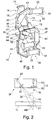
- the measuring device 10 is used to measure a three-dimensional 360 ° surface profile of an endlessly processed product strand 11 of the tobacco processing industry, for example a tobacco strand, a filter strand or a multi-segment filter strand.
- the product strand 11 is made in a strand machine 83 of the tobacco processing industry longitudinally axially promoted, see description of Figure 8 .
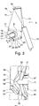
- the measuring device 10 comprises a light generating arrangement 9, which is shown in FIG Figure 3 For the sake of clarity, it is shown on its own, ie without the cameras 35-37 and the beam deflection elements 41-49 on the outlet side.
- the light generating arrangement 9 advantageously has precisely one laser light source 12 which is set up to generate a laser light fan 13 and for this purpose (see FIG Figure 2 ) for example a laser diode 74 or a laser and suitable optics 75, for example a cylindrical lens, or a movable scanning device.
- the light fan 13 is deflected via a deflection element 14, so that the deflected light fan 15, viewed along the strand direction, is approximately centered (see FIG Figure 2 ) and falls vertically onto the product strand 11.
- a collimator lens 17 is advantageously arranged in the beam path 16 incident on the product strand 11, which includes the light fans 13, 15, 18, in order to generate an approximately parallel light fan 18 from the divergent light fan 13, 15.
- the deflection by the deflection element 14 is advantageously carried out at an angle of at least 90 °, further advantageously at least 135 °, for example in the angular range between 135 ° and 180 °.
- the widened and possibly collimated incident beam path 16 is advantageously projected onto the strand 11 with the aid of mirrors 24, 25 from two additional, and thus a total of three sides, in order to obtain a light line 21 running around the circumference of the strand 11. This is explained in more detail below using the Figure 3 described.
- the incident, advantageously parallel beam path 16, 18 falls on the product strand 11 in a central region 19, which can be referred to as the main radiation fan arranged around the circumference of the product strand 11 in the area of the measuring point is to the image sensors 29-31 of the cameras 35-37 (see Figure 1 ) to keep them free from dust and foreign particles.
- An air stream flowing parallel to the wall of the protective tube 20 can be generated in order to keep the measuring area clean.
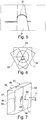
- the central region 19 of the light fan 18 incident on the product strand 11 generates a laser light line 21 on the surface of the product strand 11, in particular on a wrapping material thereof, as exemplified in FIG Figure 5 you can see.
- the parallelized light fan 18 has a total width B which is at least 3 times, advantageously at least 4 times, even more advantageously at least 5 times the width b of the product strand 11, see Figure 3 .
- a lateral region 22, 23 of the parallelized radiation fan 18 can therefore pass through the product strand 11 on both sides of the product strand 11.
- each deflection element 24, 25 is provided on one or preferably both sides of the product strand 11, each one of the lateral areas 22, 23 of the radiation fan 18 deflects in such a way that it falls as incident radiation fans 26, 27 onto the surface of the product strand 11 from the rear.
- the deflection by each deflection element 24, 25 is advantageously carried out by an angle in the range from 120 ° to 180 °, for example by 150 °. In this way, or by some other suitable beam deflection, it is achieved that the central beam axes of all three beam fans 19, 26, 27 incident on the product strand enclose angles of 120 ° to one another.
- the deflecting elements 14, 24 and 25 are arranged in the incident beam path 16 in such a way that all the beam fans 19, 26, 27 incident on the product strand strike it at the same axial position MP of the product strand 11, so that the from the fan beams 19, 26, 27 incident on the product strand mutually overlap and, overall, generate a self-contained laser line 21 that encircles the product strand 11 completely by 360 °.
- the laser line rotating 360 ° around the product line 11 21 spans a plane which intersects the central longitudinal axis of the product strand 11 at point MP.
- the laser line 21 running around the product strand 11 on its surface is recorded by means of optical triangulation.
- a plurality of light-sensitive elements 29, 30, 31 are arranged around the product strand, see FIG Figure 1 .
- the light-sensitive elements 29, 30, 31 are in particular imaging sensors which convert light incident on the light-sensitive elements 29, 30, 31 into an electrical signal that contains the image information and is evaluated by an electronic evaluation device.
- a corresponding light-sensitive element 29, 30, 31 is advantageously assigned to each incident light fan or light beam 19, 26, 27.
- a laser line that is very thin in the direction of the strand, or a laser light fan, is directed onto the product strand 11.
- the incident light beam or light fan 16, 19 falls in a view transversely to the product strand 11 (see Figure 2 ) advantageously perpendicular to its surface.
- the light-sensitive element 29 is arranged in this view in such a way that the optical axis of the light exiting from the surface of the product strand 11 encloses a triangulation angle ⁇ with the optical axis of the light incident on the surface of the product strand 11.
- the triangulation angle ⁇ is advantageously in the range between 10 ° and 80 °, further advantageously between 20 ° and 70 °, even more advantageously between 30 ° and 60 ° and optimally between 40 ° and 50 °. Due to the triangulation angle ⁇ , the surface structure of the product strand, which is reflected in a corresponding course of the laser line 21, is imaged on the light-sensitive element 29 and can be determined by calculation. In other words, the image of the projected laser light line 21 (see FIG Figure 5 ) recorded at a defined angle, namely the triangulation angle ⁇ , whereby height information is obtained. In this way, a measurement accuracy of the diameter measurement or a measurement resolution of better than 0.1 mm, for example 0.01 mm, is achieved.
- a corresponding lens 32-34 is advantageously assigned to each light-sensitive element 29-31, see FIG Figure 1 .
- each objective 32-34 has at least one, preferably a plurality of optical lenses.
- Each light-sensitive element 29-31 forms a corresponding camera 35-37 with the objective 32-34 assigned to it.
- the cameras 35-37 are arranged in such a way that the laser light lines 21 on the surface of the product strand 11 lie in the focus of the respective objective 32-34, so that the laser light lines 21 are imaged sharply on the light-sensitive elements 29-31.
- One or more of the cameras 35 to 37 can advantageously be arranged in such a way that their optical axis runs horizontally, as shown in FIG Figure 1 you can see.
- One or more beam deflection elements 41-49 are advantageously arranged between the product strand 11 and each camera 35-37.
- the cameras 35-37 can be optimally arranged depending on the available installation space in order to achieve a measuring module 50, 51 that is as compact as possible and optimally adapted to the respective installation situation (see FIG Figure 7 ) to be able to achieve.
- the beam deflection elements 41-49 can be or comprise mirrors and / or prisms, for example.
- an outgoing beam path 38 to the light-sensitive element 29 is described by way of example. The same applies in each case to the further emerging beam paths 39, 40 to the light-sensitive elements 30, 31.
- a first beam deflection element 41 can initially be provided, which deflects the beam 38 exiting at the triangulation angle ⁇ , for example, in such a way that the deflected beam 52 at an angle between 75 ° and 105 °, for example 90 ° relative to the strand axis runs. This is best in Figure 4 to see.
- the light beam 52 deflected by the first beam deflection element 41 is deflected by at least one, here two further beam deflection elements 42, 43 in such a way that the outgoing light beam 38 finally enters the camera 35.
- the total deflection by the at least one further beam deflection element 42, 43 is advantageously at least 90 ° and, for example, 135 ° or, as in the case of the light-sensitive element 31, even 180 °.
- each light-sensitive element 29, 30, 31 is advantageously arranged at the same angular distances from one another, in the preferred case of three light-sensitive elements 29, 30, 31 thus offset by 120 ° around the product strand 11.
- each light-sensitive element 29, 30, 31 covers an angular range of 120 °, or 360 ° / n in the case of n light-sensitive elements 29, 30, 31, in the circumferential direction of the product strand 11.
- the outgoing beam paths 38-40 are advantageously arranged around the product strand 11 at equal angular distances from one another. In this case, the angular distances between the light-sensitive elements 29-31 are not important, which can be arranged differently due to the light-deflecting elements 41-49.
- the beam paths are deflected starting from the laser light source 12 to the image recorders 29-31 via a plurality of mirrors 14, 24, 25, 41-49 in order to be able to optimally position the individual components 12, 29-31.
- the measuring device 10 is advantageously surrounded by a housing 53 and thus forms a measuring module 50, 51
- Figure 7 the situation for a two-strand machine for the parallel processing of two endless product strands 11 is shown.
- two measuring modules 50, 51 ie a separate measuring module 50, 51 for each product strand 11, are advantageously provided.
- the measuring modules 50, 51 can advantageously be constructed identically.
- the housing 53 of each measuring module 50, 51 advantageously has through openings 54, 55 lying opposite one another for carrying out the in Figure 7 Product strand 11, shown only schematically, through the housing 53 and thus through the measuring device 10.
- the rear through opening 55 in the rear wall of the housing 53 is shown schematically for the measuring module 50 only.
- the arrangement of the through openings 54, 55 in the housing 53 can be asymmetrical.
- the through openings 54, 55 can be arranged at a significantly smaller distance d to a nearest housing edge 56 or 57 or housing wall 58 than to any other housing edge or housing wall.
- the distance d is particularly advantageously at most half as great as the distance D between the two strands in a two-strand machine.
- identically constructed measuring modules that are only rotated by 180 ° relative to one another can be used, as in FIG Figure 7 shown.
- a rod unit 81 of a rod machine 83 of the tobacco processing industry with a measuring device 10 integrated therein is shown schematically.
- the line unit 81 is usually preceded by a distribution unit 84.
- it can be a filter rod unit 81, for example in the form of a filter tow processing unit, in a filter rod machine 83.
- it can be a filter segment assembly section 81 of a multi-segment filter strand machine 83 act.
- Such strand machines 83 and strand units 81 are well known, which is why a detailed description is dispensed with here.
- the above-described measuring device 10 is integrated in the strand unit 81 or in the strand machine 83 and thus in the production.
- An advantageous position of the measuring device 10 or the measuring module 50 in the strand unit is in the strand conveying direction between a wrapping device 59 for wrapping the material strand with a wrapping strip, for example paper, and a cutting device 60 for continuously cutting the continuous strand 11 into individual rod-shaped elements.
- the measuring module 50 comprises at least three light-sensitive elements or imaging sensors 29-31, which are arranged around the product strand 11, for example, offset by 120 ° in each case.
- Each sensor 29-31 can be assigned a controller 61, for example in the form of an FPGA and / or microcontroller, which can be used in particular for preliminary evaluation and / or for data compression.
- the data of the individual image sensor modules are transmitted via a correspondingly fast data connection 62 to a main control or data aggregation unit 63, for example also an FPGA and / or microcontroller.
- the sensor module 50 now provides profile values of the product strand 11, for example as polar coordinates or Cartesian coordinates, to a subsequent evaluation unit 65 via a fast data connection 64.
- quality values, special features of the strand and / or service data are generated from the sensor data in a computing unit 66, which receives the sensor data from the sensor module 50, in conjunction with the machine control 67.
- the data are advantageous for the machine visualization and / or parameterization 68 and / or the control and / or regulation of the manufacturing process, in particular via actuators 69 for regulation and / or actuators 70 for product selection or product scrap, used to obtain a higher product quality and a more efficient running time of the manufacturing machine.
- the main control or data summarizing unit 63 and / or the computing unit 66 according to FIG. 9 advantageously form a digital evaluation device 73 according to the claims.
- the information can also be used for data collection and analysis in a higher-level data collector 71, as well as for controlling and / or regulating upstream machines 72 in order to increase the quality of the parts to be supplied to the manufacturing machine there as well.
- measuring device 10 An advantageous application of the measuring device 10 is used to measure quality values, features and / or service data of individual segments in endlessly repeating multi-segment rod sections of a product strand 11. This will be explained below with reference to FIG Figure 10 explained.
- the endlessly processed product strand is formed from continuously repeating rod sections ..., Sn, Sn + 1, Sn + 2, ...
- Each rod section corresponds to a rod after the product rod 11 has been cut into individual rods by means of the cutting device 60 (see FIG Figure 8 ).
- the rod sections can therefore also be referred to in a simplified manner as rods.
- each rod or rod section Sn is in turn composed of the same sequence of segments T1, T2, T3, ..., the sum of the segment lengths giving the rod length.
- each rod has three segments T1, T2, T3, with more or less than three segments per rod being possible. It is therefore a question of multi-segment bars.
- the sampling rate of the measuring device is sufficiently high that a circumferential profile P of the product strand 11 can be measured at least for each segment.
- the distance a between two measurement profiles P, which results from the sampling rate is advantageously less than or equal to the shortest segment length in the product strand 11, here less than or equal to the length of the segment T2.
- the distance between two profile scans P should be at most 20 mm, advantageously at most 10 mm, further advantageously at most 5 mm, for example 3 mm.
- the sampling rate is advantageously at least 500 profile scans P per second, advantageously at least 1000 profile scans P per second, further advantageously at least 2000 profile scans P per second, even more advantageously at least 3000 profile scans P per second and, for example, 4000 profile scans P per second.
- Quality values are advantageously calculated and specified for each bar, for each segment and / or as an average value for production. These include, for example, the diameter and circumference of the product strand 11; Ovality; Out-of-roundness factor, e.g. standard deviation of the radii of an extruded profile; Seam position of a wrapping strip, for example as an angle.
- one or more standard deviations (or variances) of one or more of the aforementioned variables can contain meaningful information and can be determined for further processing. If, for example, mean values are formed from individual values, then a simultaneous specification of a standard deviation is useful, for example in order to provide early indications that production is becoming more restless and To receive upcoming errors, e.g. due to machine contamination, and to be able to react to them in good time.
- features of the product strand to be determined are in particular those that are noticeable as defects in the product, i.e. in the cut strand.
- a defective product is then advantageously selected or removed from production.
- Features of this type are, for example, profile defects on sections of the strand and / or on individual segments; Adhesive points of a wrapping strip in the continuous strand course; Glued joint defects in a glued seam on sections of the strand; Foreign body build-up on a piece of string.
- Service information is important for machine setters, service personnel and machine operators in order to obtain information about reliable production and, if necessary, to be able to intervene in the production process to correct it.
- Service data of this type are, for example, string swing; restless longitudinal seam of a wrapping strip, for example as a standard deviation over production; Profile plot; 3D plot.
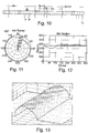
- FIG. 11 An example of a profile plot of a scan is given in the Figures 11 and 12 shown.
- Figure 11 a profile plot in polar coordinates is shown.
- Figure 12 the same circumferential profile is plotted in a Cartesian coordinate system as a radius over the angle or as a function of the angle.
- the faulty flattening of the profile and thus of the product strand in the range between 0 ° and 120 ° can be clearly seen.
- FIG. 13 An example of a 3D profile plot which is composed of several individual profile plots according to FIG. 11 one behind the other in the production direction is shown in FIG Figure 13 shown.
- the graphic only shows the partial profile corresponding to an image sensor.
- the complete 360 ° profile can also be displayed.
- a thickening in the rear area can be seen in the image; this can be, for example, a single segment of greater thickness.
- a longitudinal fold is visible in the light area of the front edge.
- a line of light or a light-dark edge in particular composed of structured light, can also be used.
Landscapes
- Physics & Mathematics (AREA)
- General Physics & Mathematics (AREA)
- Health & Medical Sciences (AREA)
- Life Sciences & Earth Sciences (AREA)
- Chemical & Material Sciences (AREA)
- Analytical Chemistry (AREA)
- Biochemistry (AREA)
- General Health & Medical Sciences (AREA)
- Immunology (AREA)
- Pathology (AREA)
- Length Measuring Devices By Optical Means (AREA)
Claims (14)
- Dispositif de mesure optique (10) pour déterminer au moins une caractéristique, une valeur de qualité et/ou des données de service d'un boudin de produit (11) traité sans fin de l'industrie de traitement du tabac sur la base de la triangulation, comprenant :- une source de lumière (12) pour générer une pluralité de trajets de faisceau incidents (16) qui sont incidents autour de la circonférence du boudin de produit (11) sur la surface de celle-ci ;- au moins trois éléments photosensibles (29-31) qui sont disposés dans un agencement de triangulation par rapport aux trajets de faisceau incidents (16),- un dispositif d'évaluation numérique (73) qui est conçu pour déterminer un profil de surface tridimensionnel du boudin de produit (11) à partir des signaux de mesure transmis par les éléments photosensibles (29-31),dans lequel le dispositif de mesure optique (10) présente au moins un élément de déviation de lumière (14) entre la source de lumière (12) et le boudin de produit (11) pour dévier au moins un trajet de faisceau incident (16), caractérisé en ce que en ce que le dispositif de mesure (10) présente exactement une source de lumière (12), dans lequel la source de lumière (12) est conçue pour générer un éventail de rayonnement principal (15), dans lequel une partie (19) de l'éventail de rayonnement principal (15) est incidente sur le boudin de produit (11) et une autre partie de l'éventail de rayonnement principal (22, 23) passe le long du boudin de produit (11) sur un ou deux côtés de celle-ci et, après avoir passé le boudin de produit (11), est dirigée sur le boudin de produit (11) par au moins un autre élément de déviation de lumière (24, 25), dans lequel les éléments de déviation de lumière (14, 24, 25) sont disposés dans le trajet de faisceau incident (16) de telle sorte que les éventails de rayons (19, 26, 27) incidents sur le boudin de produit (11) produisent au total une ligne lumineuse fermée qui fait le tour complet sur 360° du boudin de produit (11).
- Dispositif de mesure optique (10) selon la revendication 1, caractérisé en ce que le dispositif de mesure optique (10) présente au moins un élément de déviation de lumière (41, 42, 43) entre le boudin de produit (11) et au moins un des éléments photosensibles (29, 30) pour dévier au moins un trajet de faisceau sortant (38-40).
- Dispositif de mesure optique (10) selon l'une des revendications précédentes, caractérisé en ce que le dispositif de mesure optique (10) présente au moins ou exactement trois trajets de faisceau incident (16) disposés autour de la circonférence du boudin de produit (11).
- Dispositif de mesure optique (10) selon l'une des revendications précédentes, caractérisé en ce qu'une lentille collimatrice (17) est disposée dans le trajet de faisceau incident (16).
- Dispositif de mesure optique (10) selon l'une des revendications précédentes, caractérisé en ce qu'au moins un élément de déviation de lumière (41-43 ; 44-46 ; 47-49) est disposé dans chaque trajet de faisceau sortant (38, 39, 40).
- Dispositif de mesure optique (10) selon l'une des revendications précédentes, caractérisé en ce que le dispositif d'évaluation (73) est conçu pour déterminer une ou plusieurs des valeurs de qualité, caractéristiques ou données de service suivantes du boudin de produit (11) à partir du profil de surface tridimensionnel :- diamètre ;- circonférence ;- ovalité ;- facteur de non-circularité ;- emplacement de suture d'une bande d'enveloppe ;- écart-type d'une ou plusieurs des grandeurs ci-dessus ;- erreurs de profil ;- points de collage d'une bande d'enveloppe ;- défauts de collage d'une ligne de collage ;- adhérences de corps étrangers ;- oscillations du boudin ;- suture longitudinale instable d'une bande d'enveloppe ;- tracé du profil ;- tracé 3D.
- Dispositif de mesure optique (10) selon l'une des revendications précédentes, caractérisé en ce que les éléments photosensibles (29-31) sont des capteurs imageurs sensibles à la position, en particulier des capteurs CMOS, et/ou que les trajets de faisceau incidents (16) sont incidents verticalement sur le boudin de produit et/ou que le plan image des éléments photosensibles (29-31) est disposé obliquement par rapport à l'axe optique respectif.
- Dispositif de mesure optique (10) selon l'une des revendications précédentes, caractérisé en ce que la fréquence d'échantillonnage du dispositif de mesure (10) est choisie de telle sorte que la distance, a, entre deux profils de mesure, P, soit inférieure ou égale à la longueur de segment la plus courte dans le boudin de produit (11).
- Dispositif de mesure optique (10) selon l'une des revendications précédentes, caractérisé en ce qu'un dispositif de commande (61), en particulier un FPGA et/ou un microprocesseur, est associé à chaque élément photosensible (29-31) ou à tous les éléments photosensibles (29-31) pour le prétraitement, la pré-évaluation et/ou la compression de données des signaux de l'élément photosensible (29-31).
- Dispositif de mesure optique (10) selon la revendication 9, caractérisé en ce que les données du dispositif de commande (61) ou de tous les dispositifs de commande (61) sont envoyées à une unité principale de commande et/ou de collecte de données (63), en particulier un FPGA et/ou un microprocesseur, pour la suite du traitement.
- Module de mesure (50, 51) comprenant un dispositif de mesure optique (10) selon l'une des revendications précédentes et un boîtier (53) entourant le dispositif de mesure (10) et présentant des ouvertures de passage (54, 55) pour faire passer le boudin de produit (11) à travers le module de mesure (50, 51).
- Module de mesure (50, 51) selon la revendication 11, caractérisé en ce que la distance d d'une ouverture de passage au bord de boîtier le plus proche (56) est inférieure ou égale à la moitié de la distance, D, de deux boudins de produit (11) à traiter dans une machine à deux boudins.
- Utilisation d'un dispositif de mesure optique (10) selon l'une des revendications 1 à 10 pour mesurer des valeurs de qualité, des caractéristiques et/ou des données de service de segments individuels, Tl, T2, T3, dans des parties en forme de tige multi-segments, Sn, se répétant sans fin, d'un boudin de produit (11).
- Procédé de mesure optique de valeurs de qualité, de caractéristiques et/ou de données de service d'un boudin de produit (11) traité sans fin de l'industrie de traitement du tabac, au moyen d'un dispositif de mesure optique (10) selon l'une des revendications 1 à 10, caractérisé en ce que la mesure est effectuée de manière synchrone avec la division du boudin de produit (11) en tiges, Sn, et/ou en segments de tiges, Tl, T2, T3, et/ou de manière synchrone avec la vitesse de production.
Priority Applications (1)
| Application Number | Priority Date | Filing Date | Title |
|---|---|---|---|
| PL19178947T PL3587998T3 (pl) | 2018-06-29 | 2019-06-07 | Urządzenie i sposób pomiaru optycznego na kablu produktu przemysłu tytoniowego i zastosowanie optycznego urządzenia pomiarowego |
Applications Claiming Priority (2)
| Application Number | Priority Date | Filing Date | Title |
|---|---|---|---|
| DE102018115753 | 2018-06-29 | ||
| DE102018129256.2A DE102018129256A1 (de) | 2018-06-29 | 2018-11-21 | Vorrichtung und Verfahren zur optischen Messung an einem Produktstrang der Tabak verarbeitenden Industrie und Verwendung einer optischen Messvorrichtung |
Publications (2)
| Publication Number | Publication Date |
|---|---|
| EP3587998A1 EP3587998A1 (fr) | 2020-01-01 |
| EP3587998B1 true EP3587998B1 (fr) | 2021-09-22 |
Family
ID=66793810
Family Applications (1)
| Application Number | Title | Priority Date | Filing Date |
|---|---|---|---|
| EP19178947.8A Active EP3587998B1 (fr) | 2018-06-29 | 2019-06-07 | Dispositif et procédé de mesure optique d'un boudin de produit de l'industrie de traitement du tabac et utilisation d'un dispositif de mesure optique |
Country Status (2)
| Country | Link |
|---|---|
| EP (1) | EP3587998B1 (fr) |
| PL (1) | PL3587998T3 (fr) |
Cited By (1)
| Publication number | Priority date | Publication date | Assignee | Title |
|---|---|---|---|---|
| EP4343276A1 (fr) * | 2022-09-21 | 2024-03-27 | International Tobacco Machinery Poland Sp. z o.o. | Procédé de mesure d'un diamètre d'une tige continue de produits de l'industrie du tabac |
Families Citing this family (1)
| Publication number | Priority date | Publication date | Assignee | Title |
|---|---|---|---|---|
| WO2025238688A1 (fr) * | 2024-05-13 | 2025-11-20 | 日本たばこ産業株式会社 | Dispositif et procédé d'inspection d'articles en forme de tige |
Family Cites Families (5)
| Publication number | Priority date | Publication date | Assignee | Title |
|---|---|---|---|---|
| DE10304503A1 (de) | 2003-02-05 | 2004-08-19 | Hauni Maschinenbau Ag | Vorrichtung und Verfahren zum Messen des Durchmessers eines stabförmigen Gegenstandes insbesondere der tabakverarbeitenden Industrie |
| DE102004057092A1 (de) | 2004-11-25 | 2006-06-01 | Hauni Maschinenbau Ag | Messen des Durchmessers von stabförmigen Artikeln der Tabak verarbeitenden Industrie |
| DE102005058873A1 (de) * | 2005-12-09 | 2007-06-14 | Fraunhofer-Gesellschaft zur Förderung der angewandten Forschung e.V. | Vorrichtung und Verfahren zur Vermessung der Oberfläche eines Körpers |
| DE102011013661A1 (de) * | 2011-03-08 | 2012-09-13 | Hauni Maschinenbau Ag | Steuerungsvorrichtung und Steuerungsverfahren für eine Maschine zur Herstellung stabförmiger Artikel der Tabak verarbeitenden Industrie |
| DE102012204331A1 (de) * | 2012-03-19 | 2013-09-19 | Hauni Maschinenbau Ag | Herstellmaschine und Verfahren zum Betrieb einer Herstellmaschine von stabförmigen Artikeln der Tabak verarbeitenden Industrie |
-
2019
- 2019-06-07 PL PL19178947T patent/PL3587998T3/pl unknown
- 2019-06-07 EP EP19178947.8A patent/EP3587998B1/fr active Active
Cited By (2)
| Publication number | Priority date | Publication date | Assignee | Title |
|---|---|---|---|---|
| EP4343276A1 (fr) * | 2022-09-21 | 2024-03-27 | International Tobacco Machinery Poland Sp. z o.o. | Procédé de mesure d'un diamètre d'une tige continue de produits de l'industrie du tabac |
| WO2024062022A1 (fr) * | 2022-09-21 | 2024-03-28 | International Tobacco Machinery Poland Sp. Z O.O. | Procédé de mesure d'un diamètre d'une tige continue de produits de l'industrie du tabac |
Also Published As
| Publication number | Publication date |
|---|---|
| EP3587998A1 (fr) | 2020-01-01 |
| PL3587998T3 (pl) | 2022-01-31 |
Similar Documents
| Publication | Publication Date | Title |
|---|---|---|
| EP2677273B1 (fr) | Dispositif de mesure et procédé de contrôle optique d'une surface frontale d'un produit en forme de tige de l'industrie de traitement du tabac acheminé dans le sens transversal-axial | |
| DE102018123363B4 (de) | Verfahren zur Kollisionsvermeidung und Laserbearbeitungsmaschine | |
| EP2918180B2 (fr) | Contrôle optique d'articles en forme de tige de l'industrie de traitement du tabac | |
| DE102010049672B3 (de) | Laser-Doppler-Linien-Distanzsensor zur dreidimensionalen Formvermessung bewegter Festkörper | |
| EP2498157B1 (fr) | Dispositif de commande et procédé de commande pour une machine de fabrication d'articles de l'industrie de traitement du tabac en forme de tige | |
| EP2679950B1 (fr) | Dispositif et procédé d'évaluation d'une surface frontale d'un produit en forme de tige de l'industrie de traitement du tabac | |
| EP2341313A1 (fr) | Dispositif de balayage | |
| DE3043849A1 (de) | Verfahren zum beschauen einer reflektierenden und/oder transparenten, sich bewegenden bahn und beschaumaschine zur durchfuehrung des verfahrens | |
| EP3587998B1 (fr) | Dispositif et procédé de mesure optique d'un boudin de produit de l'industrie de traitement du tabac et utilisation d'un dispositif de mesure optique | |
| WO2020099323A1 (fr) | Procédé pour détecter une zone de travail d'un dispositif de fabrication additive, et dispositif de fabrication pour une fabrication additive d'éléments à partir d'une matière pulvérulente | |
| DE3541142C2 (de) | Kontroll- und Korrekturvorrichtung der Querabmessungen von stabförmigen Produkten, insbesondere für Konfektioniermaschinen für Rauchwaren | |
| EP0159354A1 (fr) | Procede et installation de mesure pluridimensionnelle d'un objet. | |
| EP1047917B1 (fr) | Procede et dispositif pour mesurer la longueur de fibres | |
| DE102014104338A1 (de) | Verfahren und Vorrichtung zur Detektion von Oberflächendeformationen | |
| EP1445576B1 (fr) | Dispositif pour la mesure synchrone du diamètre d'objets en barre de l'industrie du tabac | |
| WO2016000764A1 (fr) | Système de détection confocal chromatique | |
| DE68921425T2 (de) | Optische Einrichtung für die Prüfung des Endes von Zigaretten. | |
| DE102018129256A1 (de) | Vorrichtung und Verfahren zur optischen Messung an einem Produktstrang der Tabak verarbeitenden Industrie und Verwendung einer optischen Messvorrichtung | |
| DE69715350T2 (de) | Verfahren und Vorrichtung zur berührungslosen Prüfung des Endes von Zigaretten oder dergleichen | |
| EP1479303B1 (fr) | Appareil pour mesurer le diamètre d'un article en forme de tige, notamment de l'industrie du tabac | |
| WO2019115209A1 (fr) | Dispositif de détection optique 3d sans contact d'une surface frontale d'un article en forme de tige de l'industrie de la transformation du tabac se déplaçant transversalement à son axe | |
| EP1647800B1 (fr) | Méthode et dispositif pour la mesure du diamètre d'un article en forme de tige notamment de l'industrie du tabac | |
| WO2017182362A1 (fr) | Dispositif et procédé de contrôle par voie optique d'articles en forme de tige de l'industrie de traitement du tabac | |
| EP3552501B2 (fr) | Dispositif et procédé d'inspection d'une surface frontale d'un article à fumer en forme de tige | |
| EP2883625B1 (fr) | Appareil de tri laser à fibre optique |
Legal Events
| Date | Code | Title | Description |
|---|---|---|---|
| PUAI | Public reference made under article 153(3) epc to a published international application that has entered the european phase |
Free format text: ORIGINAL CODE: 0009012 |
|
| STAA | Information on the status of an ep patent application or granted ep patent |
Free format text: STATUS: THE APPLICATION HAS BEEN PUBLISHED |
|
| AK | Designated contracting states |
Kind code of ref document: A1 Designated state(s): AL AT BE BG CH CY CZ DE DK EE ES FI FR GB GR HR HU IE IS IT LI LT LU LV MC MK MT NL NO PL PT RO RS SE SI SK SM TR |
|
| AX | Request for extension of the european patent |
Extension state: BA ME |
|
| STAA | Information on the status of an ep patent application or granted ep patent |
Free format text: STATUS: REQUEST FOR EXAMINATION WAS MADE |
|
| 17P | Request for examination filed |
Effective date: 20200630 |
|
| RBV | Designated contracting states (corrected) |
Designated state(s): AL AT BE BG CH CY CZ DE DK EE ES FI FR GB GR HR HU IE IS IT LI LT LU LV MC MK MT NL NO PL PT RO RS SE SI SK SM TR |
|
| RIC1 | Information provided on ipc code assigned before grant |
Ipc: G01N 21/952 20060101ALN20210310BHEP Ipc: G01B 11/10 20060101ALN20210310BHEP Ipc: A24C 5/34 20060101ALN20210310BHEP Ipc: G01B 11/245 20060101AFI20210310BHEP |
|
| GRAP | Despatch of communication of intention to grant a patent |
Free format text: ORIGINAL CODE: EPIDOSNIGR1 |
|
| STAA | Information on the status of an ep patent application or granted ep patent |
Free format text: STATUS: GRANT OF PATENT IS INTENDED |
|
| RIC1 | Information provided on ipc code assigned before grant |
Ipc: G01N 21/952 20060101ALN20210325BHEP Ipc: G01B 11/10 20060101ALN20210325BHEP Ipc: A24C 5/34 20060101ALN20210325BHEP Ipc: G01B 11/245 20060101AFI20210325BHEP |
|
| INTG | Intention to grant announced |
Effective date: 20210421 |
|
| GRAS | Grant fee paid |
Free format text: ORIGINAL CODE: EPIDOSNIGR3 |
|
| GRAA | (expected) grant |
Free format text: ORIGINAL CODE: 0009210 |
|
| STAA | Information on the status of an ep patent application or granted ep patent |
Free format text: STATUS: THE PATENT HAS BEEN GRANTED |
|
| AK | Designated contracting states |
Kind code of ref document: B1 Designated state(s): AL AT BE BG CH CY CZ DE DK EE ES FI FR GB GR HR HU IE IS IT LI LT LU LV MC MK MT NL NO PL PT RO RS SE SI SK SM TR |
|
| REG | Reference to a national code |
Ref country code: GB Ref legal event code: FG4D Free format text: NOT ENGLISH |
|
| REG | Reference to a national code |
Ref country code: DE Ref legal event code: R096 Ref document number: 502019002322 Country of ref document: DE |
|
| REG | Reference to a national code |
Ref country code: IE Ref legal event code: FG4D Free format text: LANGUAGE OF EP DOCUMENT: GERMAN |
|
| REG | Reference to a national code |
Ref country code: CH Ref legal event code: EP Ref country code: AT Ref legal event code: REF Ref document number: 1432653 Country of ref document: AT Kind code of ref document: T Effective date: 20211015 |
|
| REG | Reference to a national code |
Ref country code: LT Ref legal event code: MG9D |
|
| REG | Reference to a national code |
Ref country code: NL Ref legal event code: FP |
|
| PG25 | Lapsed in a contracting state [announced via postgrant information from national office to epo] |
Ref country code: LT Free format text: LAPSE BECAUSE OF FAILURE TO SUBMIT A TRANSLATION OF THE DESCRIPTION OR TO PAY THE FEE WITHIN THE PRESCRIBED TIME-LIMIT Effective date: 20210922 Ref country code: BG Free format text: LAPSE BECAUSE OF FAILURE TO SUBMIT A TRANSLATION OF THE DESCRIPTION OR TO PAY THE FEE WITHIN THE PRESCRIBED TIME-LIMIT Effective date: 20211222 Ref country code: HR Free format text: LAPSE BECAUSE OF FAILURE TO SUBMIT A TRANSLATION OF THE DESCRIPTION OR TO PAY THE FEE WITHIN THE PRESCRIBED TIME-LIMIT Effective date: 20210922 Ref country code: NO Free format text: LAPSE BECAUSE OF FAILURE TO SUBMIT A TRANSLATION OF THE DESCRIPTION OR TO PAY THE FEE WITHIN THE PRESCRIBED TIME-LIMIT Effective date: 20211222 Ref country code: SE Free format text: LAPSE BECAUSE OF FAILURE TO SUBMIT A TRANSLATION OF THE DESCRIPTION OR TO PAY THE FEE WITHIN THE PRESCRIBED TIME-LIMIT Effective date: 20210922 Ref country code: RS Free format text: LAPSE BECAUSE OF FAILURE TO SUBMIT A TRANSLATION OF THE DESCRIPTION OR TO PAY THE FEE WITHIN THE PRESCRIBED TIME-LIMIT Effective date: 20210922 Ref country code: FI Free format text: LAPSE BECAUSE OF FAILURE TO SUBMIT A TRANSLATION OF THE DESCRIPTION OR TO PAY THE FEE WITHIN THE PRESCRIBED TIME-LIMIT Effective date: 20210922 |
|
| PG25 | Lapsed in a contracting state [announced via postgrant information from national office to epo] |
Ref country code: LV Free format text: LAPSE BECAUSE OF FAILURE TO SUBMIT A TRANSLATION OF THE DESCRIPTION OR TO PAY THE FEE WITHIN THE PRESCRIBED TIME-LIMIT Effective date: 20210922 Ref country code: GR Free format text: LAPSE BECAUSE OF FAILURE TO SUBMIT A TRANSLATION OF THE DESCRIPTION OR TO PAY THE FEE WITHIN THE PRESCRIBED TIME-LIMIT Effective date: 20211223 |
|
| PG25 | Lapsed in a contracting state [announced via postgrant information from national office to epo] |
Ref country code: IS Free format text: LAPSE BECAUSE OF FAILURE TO SUBMIT A TRANSLATION OF THE DESCRIPTION OR TO PAY THE FEE WITHIN THE PRESCRIBED TIME-LIMIT Effective date: 20220122 Ref country code: SK Free format text: LAPSE BECAUSE OF FAILURE TO SUBMIT A TRANSLATION OF THE DESCRIPTION OR TO PAY THE FEE WITHIN THE PRESCRIBED TIME-LIMIT Effective date: 20210922 Ref country code: RO Free format text: LAPSE BECAUSE OF FAILURE TO SUBMIT A TRANSLATION OF THE DESCRIPTION OR TO PAY THE FEE WITHIN THE PRESCRIBED TIME-LIMIT Effective date: 20210922 Ref country code: PT Free format text: LAPSE BECAUSE OF FAILURE TO SUBMIT A TRANSLATION OF THE DESCRIPTION OR TO PAY THE FEE WITHIN THE PRESCRIBED TIME-LIMIT Effective date: 20220124 Ref country code: ES Free format text: LAPSE BECAUSE OF FAILURE TO SUBMIT A TRANSLATION OF THE DESCRIPTION OR TO PAY THE FEE WITHIN THE PRESCRIBED TIME-LIMIT Effective date: 20210922 Ref country code: EE Free format text: LAPSE BECAUSE OF FAILURE TO SUBMIT A TRANSLATION OF THE DESCRIPTION OR TO PAY THE FEE WITHIN THE PRESCRIBED TIME-LIMIT Effective date: 20210922 Ref country code: CZ Free format text: LAPSE BECAUSE OF FAILURE TO SUBMIT A TRANSLATION OF THE DESCRIPTION OR TO PAY THE FEE WITHIN THE PRESCRIBED TIME-LIMIT Effective date: 20210922 Ref country code: AL Free format text: LAPSE BECAUSE OF FAILURE TO SUBMIT A TRANSLATION OF THE DESCRIPTION OR TO PAY THE FEE WITHIN THE PRESCRIBED TIME-LIMIT Effective date: 20210922 |
|
| REG | Reference to a national code |
Ref country code: DE Ref legal event code: R097 Ref document number: 502019002322 Country of ref document: DE |
|
| PG25 | Lapsed in a contracting state [announced via postgrant information from national office to epo] |
Ref country code: DK Free format text: LAPSE BECAUSE OF FAILURE TO SUBMIT A TRANSLATION OF THE DESCRIPTION OR TO PAY THE FEE WITHIN THE PRESCRIBED TIME-LIMIT Effective date: 20210922 |
|
| PLBE | No opposition filed within time limit |
Free format text: ORIGINAL CODE: 0009261 |
|
| STAA | Information on the status of an ep patent application or granted ep patent |
Free format text: STATUS: NO OPPOSITION FILED WITHIN TIME LIMIT |
|
| 26N | No opposition filed |
Effective date: 20220623 |
|
| REG | Reference to a national code |
Ref country code: DE Ref legal event code: R081 Ref document number: 502019002322 Country of ref document: DE Owner name: KOERBER TECHNOLOGIES GMBH, DE Free format text: FORMER OWNER: HAUNI MASCHINENBAU GMBH, 21033 HAMBURG, DE |
|
| REG | Reference to a national code |
Ref country code: NL Ref legal event code: HC Owner name: KOERBER TECHNOLOGIES GMBH; DE Free format text: DETAILS ASSIGNMENT: CHANGE OF OWNER(S), CHANGE OF OWNER(S) NAME; FORMER OWNER NAME: HAUNI MASCHINENBAU GMBH Effective date: 20221031 |
|
| PG25 | Lapsed in a contracting state [announced via postgrant information from national office to epo] |
Ref country code: SI Free format text: LAPSE BECAUSE OF FAILURE TO SUBMIT A TRANSLATION OF THE DESCRIPTION OR TO PAY THE FEE WITHIN THE PRESCRIBED TIME-LIMIT Effective date: 20210922 |
|
| PG25 | Lapsed in a contracting state [announced via postgrant information from national office to epo] |
Ref country code: MC Free format text: LAPSE BECAUSE OF FAILURE TO SUBMIT A TRANSLATION OF THE DESCRIPTION OR TO PAY THE FEE WITHIN THE PRESCRIBED TIME-LIMIT Effective date: 20210922 |
|
| REG | Reference to a national code |
Ref country code: CH Ref legal event code: PL |
|
| REG | Reference to a national code |
Ref country code: BE Ref legal event code: MM Effective date: 20220630 |
|
| PG25 | Lapsed in a contracting state [announced via postgrant information from national office to epo] |
Ref country code: LU Free format text: LAPSE BECAUSE OF NON-PAYMENT OF DUE FEES Effective date: 20220607 Ref country code: LI Free format text: LAPSE BECAUSE OF NON-PAYMENT OF DUE FEES Effective date: 20220630 Ref country code: IE Free format text: LAPSE BECAUSE OF NON-PAYMENT OF DUE FEES Effective date: 20220607 Ref country code: FR Free format text: LAPSE BECAUSE OF NON-PAYMENT OF DUE FEES Effective date: 20220630 Ref country code: CH Free format text: LAPSE BECAUSE OF NON-PAYMENT OF DUE FEES Effective date: 20220630 |
|
| PG25 | Lapsed in a contracting state [announced via postgrant information from national office to epo] |
Ref country code: BE Free format text: LAPSE BECAUSE OF NON-PAYMENT OF DUE FEES Effective date: 20220630 |
|
| P01 | Opt-out of the competence of the unified patent court (upc) registered |
Effective date: 20230621 |
|
| GBPC | Gb: european patent ceased through non-payment of renewal fee |
Effective date: 20230607 |
|
| PG25 | Lapsed in a contracting state [announced via postgrant information from national office to epo] |
Ref country code: SM Free format text: LAPSE BECAUSE OF FAILURE TO SUBMIT A TRANSLATION OF THE DESCRIPTION OR TO PAY THE FEE WITHIN THE PRESCRIBED TIME-LIMIT Effective date: 20210922 Ref country code: MK Free format text: LAPSE BECAUSE OF FAILURE TO SUBMIT A TRANSLATION OF THE DESCRIPTION OR TO PAY THE FEE WITHIN THE PRESCRIBED TIME-LIMIT Effective date: 20210922 Ref country code: CY Free format text: LAPSE BECAUSE OF FAILURE TO SUBMIT A TRANSLATION OF THE DESCRIPTION OR TO PAY THE FEE WITHIN THE PRESCRIBED TIME-LIMIT Effective date: 20210922 Ref country code: GB Free format text: LAPSE BECAUSE OF NON-PAYMENT OF DUE FEES Effective date: 20230607 |
|
| PG25 | Lapsed in a contracting state [announced via postgrant information from national office to epo] |
Ref country code: HU Free format text: LAPSE BECAUSE OF FAILURE TO SUBMIT A TRANSLATION OF THE DESCRIPTION OR TO PAY THE FEE WITHIN THE PRESCRIBED TIME-LIMIT; INVALID AB INITIO Effective date: 20190607 |
|
| PG25 | Lapsed in a contracting state [announced via postgrant information from national office to epo] |
Ref country code: MT Free format text: LAPSE BECAUSE OF FAILURE TO SUBMIT A TRANSLATION OF THE DESCRIPTION OR TO PAY THE FEE WITHIN THE PRESCRIBED TIME-LIMIT Effective date: 20210922 |
|
| PGFP | Annual fee paid to national office [announced via postgrant information from national office to epo] |
Ref country code: PL Payment date: 20250522 Year of fee payment: 7 |
|
| PGFP | Annual fee paid to national office [announced via postgrant information from national office to epo] |
Ref country code: NL Payment date: 20250621 Year of fee payment: 7 |
|
| REG | Reference to a national code |
Ref country code: AT Ref legal event code: MM01 Ref document number: 1432653 Country of ref document: AT Kind code of ref document: T Effective date: 20240607 |
|
| PGFP | Annual fee paid to national office [announced via postgrant information from national office to epo] |
Ref country code: DE Payment date: 20250630 Year of fee payment: 7 |
|
| PGFP | Annual fee paid to national office [announced via postgrant information from national office to epo] |
Ref country code: IT Payment date: 20250627 Year of fee payment: 7 |
|
| PG25 | Lapsed in a contracting state [announced via postgrant information from national office to epo] |
Ref country code: AT Free format text: LAPSE BECAUSE OF NON-PAYMENT OF DUE FEES Effective date: 20240607 |
|
| PG25 | Lapsed in a contracting state [announced via postgrant information from national office to epo] |
Ref country code: TR Free format text: LAPSE BECAUSE OF FAILURE TO SUBMIT A TRANSLATION OF THE DESCRIPTION OR TO PAY THE FEE WITHIN THE PRESCRIBED TIME-LIMIT Effective date: 20210922 |
|
| PGFP | Annual fee paid to national office [announced via postgrant information from national office to epo] |
Ref country code: AT Payment date: 20260410 Year of fee payment: 5 |