EP3588606B1 - Corps de base destiné à la traversée d'une conduites ainsi que partie de boitier d'un boitier, en particulier d'un boitier de batterie doté d' un tel corps de base - Google Patents
Corps de base destiné à la traversée d'une conduites ainsi que partie de boitier d'un boitier, en particulier d'un boitier de batterie doté d' un tel corps de base Download PDFInfo
- Publication number
- EP3588606B1 EP3588606B1 EP19180797.3A EP19180797A EP3588606B1 EP 3588606 B1 EP3588606 B1 EP 3588606B1 EP 19180797 A EP19180797 A EP 19180797A EP 3588606 B1 EP3588606 B1 EP 3588606B1
- Authority
- EP
- European Patent Office
- Prior art keywords
- base body
- welding
- housing part
- housing
- glass
- Prior art date
- Legal status (The legal status is an assumption and is not a legal conclusion. Google has not performed a legal analysis and makes no representation as to the accuracy of the status listed.)
- Active
Links
Images



Classifications
-
- H—ELECTRICITY
- H01—ELECTRIC ELEMENTS
- H01M—PROCESSES OR MEANS, e.g. BATTERIES, FOR THE DIRECT CONVERSION OF CHEMICAL ENERGY INTO ELECTRICAL ENERGY
- H01M50/00—Constructional details or processes of manufacture of the non-active parts of electrochemical cells other than fuel cells, e.g. hybrid cells
- H01M50/50—Current conducting connections for cells or batteries
- H01M50/502—Interconnectors for connecting terminals of adjacent batteries; Interconnectors for connecting cells outside a battery casing
- H01M50/514—Methods for interconnecting adjacent batteries or cells
- H01M50/516—Methods for interconnecting adjacent batteries or cells by welding, soldering or brazing
-
- C—CHEMISTRY; METALLURGY
- C03—GLASS; MINERAL OR SLAG WOOL
- C03C—CHEMICAL COMPOSITION OF GLASSES, GLAZES OR VITREOUS ENAMELS; SURFACE TREATMENT OF GLASS; SURFACE TREATMENT OF FIBRES OR FILAMENTS MADE FROM GLASS, MINERALS OR SLAGS; JOINING GLASS TO GLASS OR OTHER MATERIALS
- C03C3/00—Glass compositions
- C03C3/12—Silica-free oxide glass compositions
- C03C3/16—Silica-free oxide glass compositions containing phosphorus
- C03C3/19—Silica-free oxide glass compositions containing phosphorus containing boron
-
- C—CHEMISTRY; METALLURGY
- C03—GLASS; MINERAL OR SLAG WOOL
- C03C—CHEMICAL COMPOSITION OF GLASSES, GLAZES OR VITREOUS ENAMELS; SURFACE TREATMENT OF GLASS; SURFACE TREATMENT OF FIBRES OR FILAMENTS MADE FROM GLASS, MINERALS OR SLAGS; JOINING GLASS TO GLASS OR OTHER MATERIALS
- C03C8/00—Enamels; Glazes; Fusion seal compositions being frit compositions having non-frit additions
- C03C8/02—Frit compositions, i.e. in a powdered or comminuted form
- C03C8/08—Frit compositions, i.e. in a powdered or comminuted form containing phosphorus
-
- C—CHEMISTRY; METALLURGY
- C03—GLASS; MINERAL OR SLAG WOOL
- C03C—CHEMICAL COMPOSITION OF GLASSES, GLAZES OR VITREOUS ENAMELS; SURFACE TREATMENT OF GLASS; SURFACE TREATMENT OF FIBRES OR FILAMENTS MADE FROM GLASS, MINERALS OR SLAGS; JOINING GLASS TO GLASS OR OTHER MATERIALS
- C03C8/00—Enamels; Glazes; Fusion seal compositions being frit compositions having non-frit additions
- C03C8/24—Fusion seal compositions being frit compositions having non-frit additions, i.e. for use as seals between dissimilar materials, e.g. glass and metal; Glass solders
-
- C—CHEMISTRY; METALLURGY
- C22—METALLURGY; FERROUS OR NON-FERROUS ALLOYS; TREATMENT OF ALLOYS OR NON-FERROUS METALS
- C22C—ALLOYS
- C22C21/00—Alloys based on aluminium
-
- C—CHEMISTRY; METALLURGY
- C22—METALLURGY; FERROUS OR NON-FERROUS ALLOYS; TREATMENT OF ALLOYS OR NON-FERROUS METALS
- C22C—ALLOYS
- C22C21/00—Alloys based on aluminium
- C22C21/02—Alloys based on aluminium with silicon as the next major constituent
-
- C—CHEMISTRY; METALLURGY
- C22—METALLURGY; FERROUS OR NON-FERROUS ALLOYS; TREATMENT OF ALLOYS OR NON-FERROUS METALS
- C22C—ALLOYS
- C22C21/00—Alloys based on aluminium
- C22C21/02—Alloys based on aluminium with silicon as the next major constituent
- C22C21/04—Modified aluminium-silicon alloys
-
- C—CHEMISTRY; METALLURGY
- C22—METALLURGY; FERROUS OR NON-FERROUS ALLOYS; TREATMENT OF ALLOYS OR NON-FERROUS METALS
- C22C—ALLOYS
- C22C21/00—Alloys based on aluminium
- C22C21/06—Alloys based on aluminium with magnesium as the next major constituent
-
- H—ELECTRICITY
- H01—ELECTRIC ELEMENTS
- H01G—CAPACITORS; CAPACITORS, RECTIFIERS, DETECTORS, SWITCHING DEVICES, LIGHT-SENSITIVE OR TEMPERATURE-SENSITIVE DEVICES OF THE ELECTROLYTIC TYPE
- H01G11/00—Hybrid capacitors, i.e. capacitors having different positive and negative electrodes; Electric double-layer [EDL] capacitors; Processes for the manufacture thereof or of parts thereof
- H01G11/74—Terminals, e.g. extensions of current collectors
-
- H—ELECTRICITY
- H01—ELECTRIC ELEMENTS
- H01G—CAPACITORS; CAPACITORS, RECTIFIERS, DETECTORS, SWITCHING DEVICES, LIGHT-SENSITIVE OR TEMPERATURE-SENSITIVE DEVICES OF THE ELECTROLYTIC TYPE
- H01G11/00—Hybrid capacitors, i.e. capacitors having different positive and negative electrodes; Electric double-layer [EDL] capacitors; Processes for the manufacture thereof or of parts thereof
- H01G11/78—Cases; Housings; Encapsulations; Mountings
- H01G11/80—Gaskets; Sealings
-
- H—ELECTRICITY
- H01—ELECTRIC ELEMENTS
- H01G—CAPACITORS; CAPACITORS, RECTIFIERS, DETECTORS, SWITCHING DEVICES, LIGHT-SENSITIVE OR TEMPERATURE-SENSITIVE DEVICES OF THE ELECTROLYTIC TYPE
- H01G2/00—Details of capacitors not covered by a single one of groups H01G4/00-H01G11/00
- H01G2/10—Housing; Encapsulation
- H01G2/103—Sealings, e.g. for lead-in wires; Covers
-
- H—ELECTRICITY
- H01—ELECTRIC ELEMENTS
- H01G—CAPACITORS; CAPACITORS, RECTIFIERS, DETECTORS, SWITCHING DEVICES, LIGHT-SENSITIVE OR TEMPERATURE-SENSITIVE DEVICES OF THE ELECTROLYTIC TYPE
- H01G9/00—Electrolytic capacitors, rectifiers, detectors, switching devices, light-sensitive or temperature-sensitive devices; Processes of their manufacture
- H01G9/004—Details
- H01G9/08—Housing; Encapsulation
- H01G9/10—Sealing, e.g. of lead-in wires
-
- H—ELECTRICITY
- H01—ELECTRIC ELEMENTS
- H01M—PROCESSES OR MEANS, e.g. BATTERIES, FOR THE DIRECT CONVERSION OF CHEMICAL ENERGY INTO ELECTRICAL ENERGY
- H01M10/00—Secondary cells; Manufacture thereof
- H01M10/05—Accumulators with non-aqueous electrolyte
- H01M10/052—Li-accumulators
-
- H—ELECTRICITY
- H01—ELECTRIC ELEMENTS
- H01M—PROCESSES OR MEANS, e.g. BATTERIES, FOR THE DIRECT CONVERSION OF CHEMICAL ENERGY INTO ELECTRICAL ENERGY
- H01M10/00—Secondary cells; Manufacture thereof
- H01M10/05—Accumulators with non-aqueous electrolyte
- H01M10/052—Li-accumulators
- H01M10/0525—Rocking-chair batteries, i.e. batteries with lithium insertion or intercalation in both electrodes; Lithium-ion batteries
-
- H—ELECTRICITY
- H01—ELECTRIC ELEMENTS
- H01M—PROCESSES OR MEANS, e.g. BATTERIES, FOR THE DIRECT CONVERSION OF CHEMICAL ENERGY INTO ELECTRICAL ENERGY
- H01M50/00—Constructional details or processes of manufacture of the non-active parts of electrochemical cells other than fuel cells, e.g. hybrid cells
- H01M50/10—Primary casings; Jackets or wrappings
- H01M50/183—Sealing members
- H01M50/186—Sealing members characterised by the disposition of the sealing members
-
- H—ELECTRICITY
- H01—ELECTRIC ELEMENTS
- H01M—PROCESSES OR MEANS, e.g. BATTERIES, FOR THE DIRECT CONVERSION OF CHEMICAL ENERGY INTO ELECTRICAL ENERGY
- H01M50/00—Constructional details or processes of manufacture of the non-active parts of electrochemical cells other than fuel cells, e.g. hybrid cells
- H01M50/10—Primary casings; Jackets or wrappings
- H01M50/183—Sealing members
- H01M50/19—Sealing members characterised by the material
- H01M50/191—Inorganic material
-
- Y—GENERAL TAGGING OF NEW TECHNOLOGICAL DEVELOPMENTS; GENERAL TAGGING OF CROSS-SECTIONAL TECHNOLOGIES SPANNING OVER SEVERAL SECTIONS OF THE IPC; TECHNICAL SUBJECTS COVERED BY FORMER USPC CROSS-REFERENCE ART COLLECTIONS [XRACs] AND DIGESTS
- Y02—TECHNOLOGIES OR APPLICATIONS FOR MITIGATION OR ADAPTATION AGAINST CLIMATE CHANGE
- Y02E—REDUCTION OF GREENHOUSE GAS [GHG] EMISSIONS, RELATED TO ENERGY GENERATION, TRANSMISSION OR DISTRIBUTION
- Y02E60/00—Enabling technologies; Technologies with a potential or indirect contribution to GHG emissions mitigation
- Y02E60/10—Energy storage using batteries
Definitions
- the invention relates to a housing component with a feedthrough for an electrical conductor, in particular for use in a battery housing.
- Rechargeable batteries preferably lithium-ion batteries
- the batteries can replace traditional energy sources such as lead-acid batteries, nickel-cadmium batteries or nickel-metal hydride batteries.
- Lithium-ion batteries have been known for many years. For example, see “ Handbook of Batteries, David Linden, Editor, 2nd Edition, McGrawhill, 1995, Chapters 36 and 39 ".
- a housing for a lithium-ion battery comprising a metal casing that is open and closed on both sides.
- the power connection or the electrodes are insulated by a plastic.
- the disadvantages of the plastic insulation are the limited temperature resistance, the limited mechanical resistance, the aging and the uncertain tightness over the service life.
- the current feedthroughs in the lithium-ion batteries according to the state of the art are therefore not sufficiently tight, in particular not hermetically sealed in the cover part of the Li-ion battery, for example.
- the electrodes are crimped and laser-welded connecting components with additional insulators in the interior of the battery.
- DE 27 33 948 A1 Related metals are iron or steel. Light metals such as aluminium are in the DE 27 33 948 A1 not described. The melting temperature of the glass or ceramic material is also specified in the DE 27 33 948 A1 not specified. In the DE 27 33 948 A1 The alkaline battery described is a battery with an alkaline electrolyte which is DE 27 33 948 A1 Sodium hydroxide or potassium hydroxide. A mention of Li-ion battery can be found in the DE 27 33 948 A1 not.
- connection pin Materials for the cell base that accommodates the via are not described, only materials for the connection pin, which can be made of titanium, aluminum, a nickel alloy or stainless steel.
- EP 0 954 045 B1 describes an RF feedthrough with improved electrical efficiency.
- Glass-to-metal feedthroughs that are formed directly within, for example, the metal wall of a packaging are described as disadvantageous because such RF feedthroughs are not durable due to the embrittlement of the glass.
- the EN 690 230 71 T2 or. EP 0 412 655 B1 describes a glass-metal feedthrough for batteries or other electrochemical cells, whereby glasses with a SiO 2 content of approximately 45 wt.% are used as the glass and metals, in particular alloys, are used which comprise molybdenum and/or chromium and/or nickel.
- the use of light metals is in the
- WO2012/110242 A4 is a passage, in particular through a housing part of a housing, in particular a battery housing, preferably made of a metal, in particular a light metal, preferably aluminum, an aluminum alloy, AlSiC, magnesium, a magnesium alloy, titanium, a titanium alloy, steel, stainless steel or stainless steel, wherein a conductor is glazed into a base body, for example with a glass or glass ceramic material and the base body with the glazed conductor is inserted into an opening of the housing component.
- WO2012/110242 A4 to connect the base body with glazed conductor to the housing component by laser welding.
- the base body is laser welded onto the housing cover of the housing part.
- the resulting tensile stress on the base body acts against the compressive stress of the glass and/or glass ceramic material on the base body and leads to leaks in the Glass and/or glass ceramic material.
- welding especially laser welding, of base bodies with a housing component made of light metal, especially aluminum, is problematic. This is especially true if the glazing in the base body is done in the form of pressure glazing.
- the inventors have recognized that when an aluminum component, for example an aluminum base body, is welded to a glass and/or glass ceramic feedthrough, another problem can arise. This is particularly the case when a pressure glazing is formed as described above. This occurs when the coefficient of expansion of the glass and/or glass ceramic material and the surrounding metal are different and the metal, for example aluminum, exerts pressure and thus tension on the glass material. As a result of the welding, the aluminum surrounding the glass material can lose its strength or its strength can at least be reduced to such an extent that it is no longer sufficient to exert a sufficiently high pressure on the glass material. The feedthrough subsequently becomes leaky. This is due to the fact that when exposed to high temperatures, the aluminum softens and loses strength, so that the necessary pressure on the glass material can no longer be built up.
- the object of the invention is to provide a housing component with a feedthrough for an electrical device, with which the problems of the prior art can be avoided.
- the invention therefore comprises a housing component and a base body for forming a glass and/or glass ceramic feedthrough, the housing components comprising aluminum and the base bodies comprising an aluminum alloy, which still has a sufficiently high yield strength after heating.
- heating preferably takes place to temperatures in the range of 450° C to 600° C, in particular 520° C to 560° C.
- heating preferably takes place to approximately 540° C.
- the aforementioned base body is connected to the housing part.
- the housing part (first body) for receiving the base body (second body) is designed such that it interacts optimally with the above-described base body and/or the above-mentioned materials.
- this design includes suitable geometries in the area of the housing part which is intended to receive the base body.
- hermetically sealed means that the helium leak rate is less than 1 + 10 -8 mbar ⁇ l/sec at a pressure difference of 1 bar.
- the material of the base body exerts a compressive stress on the glass or glass ceramic material.
- the thermal expansion coefficient of the light metal, in particular the aluminum alloy of the base body is selected to be greater than that of the glass and/or glass ceramic material into which the functional element, in particular the conductor, is glazed.
- the chemical compatibility of the metal of the base body on the one hand and the glass and/or glass ceramic material on the other hand is important for the formation of a permanently stable and resilient feedthrough.
- chemical bonding forces between the metal of the base body and the glass and/or glass ceramic material of the feedthrough in the interface area also contribute to the stability of the glazing and thus of the entire feedthrough.
- components of the metal of the base body can diffuse into the glass and/or glass ceramic material of the feedthrough, at least in an interface area. The diffused components can reduce the chemical bonding forces and/or even destabilize the glass structure, so that fractures of the feedthrough can occur.
- the base body with the glazing made of aluminum or aluminum alloy is to be welded into a housing made of aluminum or an aluminum alloy and the aluminum alloys contain different additives such as Mg, etc.
- Welding different aluminum alloys often leads to cracks. Crack-freeness and thus a high level of hermetic tightness are difficult to achieve.
- the inventors have found that the probability of crack formation increases greatly if the Mg content or the Si content in the alloy is reduced and is less than 1.5% by weight. The crack formation is due to a hardening process with different hardening temperatures of the different components during welding.
- the base body comprises at least one flange with a thickness and the proportion of additives or welding promoters, in particular the Mg proportion in the flange, is adaptable to the thickness of the flange. Conversely, it would also be possible to adapt the thickness of the flange to the proportion of additives or welding promoters.
- the counterflange has a first interface that runs essentially perpendicular to the conductor and the part of the base body, in particular the projection or flange, has a second interface that runs essentially perpendicular to the conductor.
- the first and second interfaces are directly opposite one another and/or close one another. to one another, with the counter flange of the housing part preferably engaging in the projection or flange of the base body, preferably in an L-shape.
- the first and second interfaces are preferably connected, preferably firmly connected, in particular hermetically sealed.
- the connection is made, for example, by welding, preferably laser welding. The result is a welded connection between the housing part and the base body.
- the base body and the housing part can be joined together with a lower laser energy, whereby narrower laser seams can also be realized and/or the track of the laser seam does not require particularly precise positioning.
- the amount of laser energy is essentially influenced by the material and the thickness of the material through which the welding takes place.
- the welding area comprises a first part of the base body and a second part of the housing part in a position (P 1 , P 2 ). It is particularly preferred if the position (P 1 , P 2 ) of the welding area depends on the Mg and/or Si and/or Zr content of the aluminum alloy of the base body and/or housing part. is selected. Furthermore, the welding areas are also characterized by a depth (T 1 , T 2 ), whereby the depth (T 1 , T 2 ) of the welding areas is selected depending on the Mg and/or Si and/or Zr content of the aluminum alloy.
- the base body has a flange or projection and the housing part has a cutout or a counter flange
- the base body can be connected to the housing part in a first welding area by lap welding and in a second welding area by butt welding.
- the second welding area in butt welding has a position (P 1 , P 2 ) depending on the Mg content of the aluminum alloy of the base body and/or housing part.
- the cutout or counterflange of the housing part has a first boundary surface running essentially perpendicular to the conductor and the part of the base body, in particular the flange or projection, has a second boundary surface running essentially perpendicular to the conductor and the first and second boundary surfaces are opposite one another.
- This can be achieved in particular by a stepped bore in the housing part.
- the term stepped bore does not mean that machining is actually used for production, but non-cutting methods for producing the desired structure are even preferred, such as embossing and/or forming.
- the feedthrough through the housing part by means of an additional base body in which the conductor is glazed, in particular the pin-shaped conductor, it is possible to prefabricate the feedthrough.
- the aforementioned glass compositions preferably have Li incorporated into the glass structure. This makes the glass compositions particularly suitable for Li-ion storage devices that comprise electrolytes based on Li, for example a 1 M LiPF 6 solution comprising a 1:1 mixture of ethylene carbonate and dimethyl carbonate.
- the metal in particular the light metal, is cleaned and/or etched, and if necessary, specifically oxidized or coated.
- temperatures between 300° C and 600 °C are used with heating rates of 0.1 to 30 K/min and holding times of 1 to 60 min.
- the laser beam welding is carried out through the housing part into the base body.
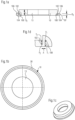
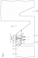
- Fig. 1d shows the two circumferential grooves 100, 102 in detail.
- the two grooves 100, 102 are formed on opposite base body surfaces 104, 106, preferably in the area of the projection or flange 30 of the base body 10.
- the grooves have different depths T 1 , T 2 .
- the groove 100 is assigned the depth T 1 , the groove 102 the depth T 2 .
- the depth T 1 is greater than T 2 in the present embodiment without being limited thereto.
- the plane of the lowest point P 1 of the groove 100 is at a distance A from the highest point P 2 of the groove 102.
- the distance A which designates the distance between the groove 100 and the groove 102, is for example 0.1 to 1 mm, preferably 0.1 to 0.5 mm.
- the depth T 1 of the groove 100 is for example 0.1 to 4 mm, preferably 1 mm to 3 mm
- the depth T 2 of the groove is in particular 0.1 to 4 mm, preferably 1 mm to 2 mm.
- a conductor preferably a pin-shaped conductor, is glazed into the opening 13 in a glass or glass-ceramic material.
- This is only possible in Fig.2 and Fig.7 shown.
- the Fig.2 and 7 The glazing of a conductor in a glass or glass ceramic material in the opening 13 shown can be easily transferred by a specialist to the other Embodiments according to Fig. 1a-6 It is particularly preferred if the thermal expansion coefficient of the base body and the glass or glass ceramic material is different.
- the thermal expansion coefficient of the base body is in the range 18 ⁇ 10 -6 /K to 30 ⁇ 10 -6 /K, that of the glass or glass ceramic material is between 15 ⁇ 10 -6 /K to 25 ⁇ 10 -6 /K. If the thermal expansion coefficient of the material of the base body is greater than that of the glass or glass ceramic material, then pressure glazing is present.
- the base body also has two circumferential grooves 100 and 102, which are also referred to as recesses.
- the grooves or recesses in the base body are arranged away from the point at which the base body is welded to the housing part.
- the two grooves 100, 102 which are preferably designed as circumferential grooves, ensure that elasticity is provided in order to protect or relieve the passage, particularly in the area of the glazing. Furthermore, the recesses or circumferential groove represent a thermal barrier that prevents heat from being introduced during glazing in the area of the points to be connected by a weld.
- the base body 1259 with a flange 1260 can be produced by cold forming or as a stepped bore.
- the thickness DA 3 of the flange is between 10 and 80%, preferably between 30 and 70% of the thickness DA 2 of the base body 1259.
- the thickness DA 2 can be selected between 3 mm and 8 mm, preferably 4 mm to 6 mm, and the thickness DA 3 between 0.5 mm and 3 mm, preferably 1 mm and 3 mm.
Landscapes
- Chemical & Material Sciences (AREA)
- Engineering & Computer Science (AREA)
- Power Engineering (AREA)
- Materials Engineering (AREA)
- Organic Chemistry (AREA)
- Chemical Kinetics & Catalysis (AREA)
- General Chemical & Material Sciences (AREA)
- Microelectronics & Electronic Packaging (AREA)
- Mechanical Engineering (AREA)
- Metallurgy (AREA)
- Electrochemistry (AREA)
- Geochemistry & Mineralogy (AREA)
- Life Sciences & Earth Sciences (AREA)
- Manufacturing & Machinery (AREA)
- Inorganic Chemistry (AREA)
- Sealing Battery Cases Or Jackets (AREA)
- Laser Beam Processing (AREA)
- Connection Of Batteries Or Terminals (AREA)
- Glass Compositions (AREA)
- Electric Double-Layer Capacitors Or The Like (AREA)
Claims (9)
- Composant de boîtier comprenant au moins deux corps en métal léger, dans lequel le premier corps est un métal léger et le deuxième corps est un métal léger avec des additifs facilitant le soudage sous la forme de composants d'alliage du métal léger et une soudure est formée entre le premier corps et le deuxième et du matériau fondu du premier corps et du matériau fondu du deuxième corps sont présents dans la soudure et forment un mélange, caractérisé en ce quele premier corps est une partie de boîtier munie d'une ouverture pour recevoir le deuxième corps et il est en aluminium, de préférence en aluminium extra-pur ;le deuxième corps est un corps de base (10) avec un conducteur électrique et un matériau à base de verre ou de vitrocéramique, le conducteur électrique étant introduit dans le matériau à base de verre ou de vitrocéramique à travers le corps de base ;le deuxième corps se compose d'un alliage d'aluminium et les additifs facilitant le soudage dans l'alliage d'aluminium comprennent Mn et/ou Mg et/ou Si et/ou Zr, les additifs facilitant le soudage représentant au total 2 à 10 % du poids, en particulier 3 à 8 % du poids, de préférence 4 à 6 % du poids et la teneur en additifs facilitant le soudage dans le mélange étant inférieure à la teneur en additifs facilitant le soudage dans le deuxième composant.
- Composant de boîtier selon la revendication 1, caractérisé en ce que l'ouverture de la partie de boîtier destinée à recevoir le corps de base (10) comporte une surface latérale lisse et le corps de base est assemblé avec la partie de boîtier (20) dans une zone de soudage (200, 202) par soudage bout à bout, la zone de soudage incluant, dans une position (P1, P2), une première partie du corps de base et une deuxième partie de la partie de boîtier.
- Composant de boîtier selon la revendication 2, caractérisé en ce que les zones de soudage (200, 202) présentent une profondeur (T1, T2).
- Composant de boîtier selon l'une des revendications 1 à 3, caractérisé en ce que le corps de base (10) comprend une bride ou une saillie (30) et la partie de boîtier (20) une découpe ou une bride opposée (25) et le corps de base (10) est assemblé avec la partie de boîtier dans une première zone de soudage (210) par soudage à recouvrement ou dans une deuxième zone de soudage (300, 310) par soudage à recouvrement ou bout à bout.
- Composant de boîtier selon la revendication 4, caractérisé en ce que la zone de soudage (200, 202) présente une profondeur (T1, T2).
- Installation électrique, en particulier installation d'accumulation, de préférence batterie ou condensateur ou supercondensateur, caractérisée en ce qu'elle comprend une partie de boîtier avec une traversée selon l'une des revendications 1 à 5.
- Procédé pour la fabrication d'un composant de boîtier selon l'une des revendications 1 à 5, comprenant les étapes suivantes :1. fourniture d'un conducteur électrique (12, 1261), pour l'essentiel un conducteur en forme de broche, et d'un corps de base (10, 1259) ;2 vitrification du conducteur électrique (12, 1261), en particulier du conducteur pour l'essentiel en forme de broche, dans un matériau à base de verre ou de vitrocéramique (14, 1262) dans le corps de base (10, 1259) ;3. assemblage du corps de base (10, 1259) avec une partie de la partie de boîtier par soudage, en particulier par soudage au laser.
- Procédé selon la revendication 7, caractérisé en ce que le corps debase (10, 1259) comporte une saillie ou une bride (30) et en ce que le corps de base (10, 1259) est enfoncé au niveau de la saillie ou de la bride (30) avant le soudage, en particulier le soudage au laser, de préférence avec un dispositif de maintien, dans une découpe ou une bride opposée (25) de la partie de boîtier, afin d'éviter un interstice entre le corps de base et la partie de boîtier,
et/oule soudage, en particulier le soudage au laser, est effectué à travers la partie de boîtier (20) dans le corps de base (10, 1259), la puissance du laser étant ajustée en fonction de l'épaisseur réduite au niveau de l'assemblage avec le corps de base dans la découpe ou la bride opposée (25). - Utilisation d'un composant de boîtier selon l'une au moins des revendications 1 à 5 dans un boîtier de batterie ou un boîtier de supercondensateurs.
Applications Claiming Priority (3)
| Application Number | Priority Date | Filing Date | Title |
|---|---|---|---|
| US15/385,166 US10224521B2 (en) | 2011-02-18 | 2016-12-20 | Feed-through |
| PCT/EP2017/082001 WO2018114392A2 (fr) | 2016-12-20 | 2017-12-08 | Corps de base servant au passage d'un conducteur ainsi que partie d'un boîtier, en particulier d'un boîter de batterie comprenant un corps de base de ce type |
| EP17816658.3A EP3560006B1 (fr) | 2016-12-20 | 2017-12-08 | Corps de base servant au passage d'un conducteur ainsi que partie d'un boîtier, en particulier d'un boîter de batterie comprenant un corps de base de ce type |
Related Parent Applications (2)
| Application Number | Title | Priority Date | Filing Date |
|---|---|---|---|
| EP17816658.3A Division-Into EP3560006B1 (fr) | 2016-12-20 | 2017-12-08 | Corps de base servant au passage d'un conducteur ainsi que partie d'un boîtier, en particulier d'un boîter de batterie comprenant un corps de base de ce type |
| EP17816658.3A Division EP3560006B1 (fr) | 2016-12-20 | 2017-12-08 | Corps de base servant au passage d'un conducteur ainsi que partie d'un boîtier, en particulier d'un boîter de batterie comprenant un corps de base de ce type |
Publications (2)
| Publication Number | Publication Date |
|---|---|
| EP3588606A1 EP3588606A1 (fr) | 2020-01-01 |
| EP3588606B1 true EP3588606B1 (fr) | 2024-07-10 |
Family
ID=60702701
Family Applications (2)
| Application Number | Title | Priority Date | Filing Date |
|---|---|---|---|
| EP19180797.3A Active EP3588606B1 (fr) | 2016-12-20 | 2017-12-08 | Corps de base destiné à la traversée d'une conduites ainsi que partie de boitier d'un boitier, en particulier d'un boitier de batterie doté d' un tel corps de base |
| EP17816658.3A Active EP3560006B1 (fr) | 2016-12-20 | 2017-12-08 | Corps de base servant au passage d'un conducteur ainsi que partie d'un boîtier, en particulier d'un boîter de batterie comprenant un corps de base de ce type |
Family Applications After (1)
| Application Number | Title | Priority Date | Filing Date |
|---|---|---|---|
| EP17816658.3A Active EP3560006B1 (fr) | 2016-12-20 | 2017-12-08 | Corps de base servant au passage d'un conducteur ainsi que partie d'un boîtier, en particulier d'un boîter de batterie comprenant un corps de base de ce type |
Country Status (5)
| Country | Link |
|---|---|
| EP (2) | EP3588606B1 (fr) |
| JP (1) | JP7009499B2 (fr) |
| KR (1) | KR102531899B1 (fr) |
| CN (2) | CN113871804B (fr) |
| WO (1) | WO2018114392A2 (fr) |
Families Citing this family (13)
| Publication number | Priority date | Publication date | Assignee | Title |
|---|---|---|---|---|
| EP3588606B1 (fr) * | 2016-12-20 | 2024-07-10 | Schott Ag | Corps de base destiné à la traversée d'une conduites ainsi que partie de boitier d'un boitier, en particulier d'un boitier de batterie doté d' un tel corps de base |
| WO2020104571A1 (fr) * | 2018-11-23 | 2020-05-28 | Schott Ag | Traversée électrique d'électrodes verre-métal |
| CN113258182B (zh) * | 2020-02-12 | 2022-10-18 | 比亚迪股份有限公司 | 电池、电池模组、电池包及电动车 |
| DE102020107224A1 (de) | 2020-03-17 | 2021-09-23 | Schott Ag | Elektrische Einrichtung |
| DE102020122910A1 (de) * | 2020-09-02 | 2022-03-03 | Schott Ag | Durchführung |
| DE102021110048A1 (de) | 2021-04-21 | 2022-10-27 | Schott Ag | Durchführung durch ein Gehäusebauteil, insbesondere für raue, mechanisch und thermisch belastete Umgebungen |
| DE202021103495U1 (de) | 2021-06-30 | 2022-10-07 | Schott Ag | Elektrische Einrichtung, insbesondere Mikrobatterie |
| CN113862498B (zh) * | 2021-08-19 | 2022-08-02 | 河南泰鸿新材料有限公司 | 一种载货汽车油箱用高强度铝板材及其生产方法 |
| DE102021134449A1 (de) * | 2021-12-23 | 2023-06-29 | Endress+Hauser SE+Co. KG | Montageanordnung mit einem vibronischen Sensor |
| JP7823457B2 (ja) * | 2022-03-28 | 2026-03-04 | 株式会社Gsユアサ | 蓄電素子 |
| JP2023144777A (ja) * | 2022-03-28 | 2023-10-11 | 株式会社Gsユアサ | 蓄電素子 |
| CN121219904A (zh) * | 2023-07-26 | 2025-12-26 | Tvs电机股份有限公司 | 用于连接储能装置中多个电芯的结构 |
| CN118617160B (zh) * | 2024-05-13 | 2025-04-18 | 杭州夸克新材料技术有限公司 | 一种用于玻璃与电热线束的焊接装置及方法 |
Family Cites Families (33)
| Publication number | Priority date | Publication date | Assignee | Title |
|---|---|---|---|---|
| US563694A (en) * | 1896-07-07 | George h | ||
| US961672A (en) | 1910-01-21 | 1910-06-14 | Henry Gregory Barnhurst | Method of burning powdered fuel. |
| JPS5399426A (en) | 1977-02-10 | 1978-08-30 | Fuji Electrochemical Co Ltd | Enclosed alkaline battery |
| US4841101A (en) | 1987-12-21 | 1989-06-20 | Pollock John A | Hermetically sealed feedthroughs and methods of making same |
| US5015530A (en) | 1988-01-21 | 1991-05-14 | The Unites States Of America As Represetned By The United States Department Of Energy | High expansion, lithium corrosion resistant sealing glasses |
| AU635043B2 (en) | 1989-07-12 | 1993-03-11 | Medtronic, Inc. | Lithium thionyl chloride resistant feedthrough |
| CA2181860A1 (fr) | 1995-07-24 | 1997-01-25 | Hitoshi Miura | Batterie secondaire au lithium a electrolyte non aqueux |
| JP3184071B2 (ja) | 1995-09-06 | 2001-07-09 | キヤノン株式会社 | リチウム二次電池 |
| US5773959A (en) | 1996-01-11 | 1998-06-30 | Lockheed Martin Corporation | Lithium polymer battery charger methods and apparatus |
| DE69700138T2 (de) | 1996-01-31 | 1999-09-02 | Aea Technology Plc | Polyvinylidenfluorid als polymerer Festelektrolyt für Lithium-Ionen-Batterien |
| KR100261252B1 (ko) | 1996-07-30 | 2000-07-01 | 윤종용 | 고분자 고체 전해질 및 이를 채용하고 있는 리튬 2차전지 |
| US5962720A (en) | 1997-05-29 | 1999-10-05 | Wilson Greatbatch Ltd. | Method of synthesizing unsymmetric organic carbonates and preparing nonaqueous electrolytes for alkali ion electrochemical cells |
| US5874185A (en) | 1997-07-24 | 1999-02-23 | Industrial Technology Research Institute | Polymer electrolyte material for use in lithium and lithium ion batteries |
| JPH11224660A (ja) * | 1997-07-29 | 1999-08-17 | Ngk Insulators Ltd | リチウム二次電池 |
| US5994975A (en) | 1998-04-28 | 1999-11-30 | Trw Inc. | Millimeter wave ceramic-metal feedthroughs |
| US6569562B1 (en) * | 1999-05-05 | 2003-05-27 | Wilson Greatbatch Ltd. | Electrochemical cell with novel header assembly |
| JP2001068205A (ja) * | 1999-08-30 | 2001-03-16 | Auto Network Gijutsu Kenkyusho:Kk | パネル取り付けコネクタ |
| US6406815B1 (en) | 2000-02-11 | 2002-06-18 | Delphi Technologies, Inc. | Compact lithium ion battery and method of manufacturing |
| WO2003061034A1 (fr) | 2002-01-09 | 2003-07-24 | Alfred E. Mann Foundation For Scientific Research | Joints hermetiques pour batteries aux ions lithium |
| FR2908928B1 (fr) | 2006-11-21 | 2009-11-27 | Commissariat Energie Atomique | Traversee etanche pour batterie au lithium, son procede de fabrication et son utilisation dans une batterie au lithium, et batterie au lithium mettant en oeuvre une telle traversee |
| DE102009011182B4 (de) | 2009-03-04 | 2017-03-23 | Schott Ag | Kristallisierendes Glaslot, Komposite und dessen Verwendung |
| KR101321666B1 (ko) * | 2011-02-01 | 2013-10-23 | 가부시키가이샤 고베 세이코쇼 | 전지 케이스용 알루미늄 합금판 및 전지 케이스 |
| CN103384649B (zh) | 2011-02-18 | 2016-09-28 | 肖特公开股份有限公司 | 贯通连接件 |
| WO2012167921A1 (fr) * | 2011-06-10 | 2012-12-13 | Schott Ag | Passage |
| JP5753317B2 (ja) * | 2011-06-28 | 2015-07-22 | シェンゼェン ビーワイディー オート アールアンドディー カンパニーリミテッド | カバーアセンブリおよびそれを備えるバッテリ |
| JP5456747B2 (ja) * | 2011-10-14 | 2014-04-02 | 株式会社神戸製鋼所 | 電池ケース用アルミニウム合金板及び電池ケース |
| CN202772203U (zh) * | 2012-09-28 | 2013-03-06 | 天津市沣文科技发展有限公司 | 新型安全柱式锂电池负极盖 |
| CN103346274B (zh) * | 2013-07-04 | 2016-01-27 | 深圳市科达利实业股份有限公司 | 动力电池电极密封装置及其制造方法 |
| CH708666A1 (de) * | 2013-10-08 | 2015-04-15 | Kistler Holding Ag | Verfahren zur Herstellung einer Metall-Keramiklötverbindung. |
| US9457542B2 (en) * | 2014-01-10 | 2016-10-04 | Shiroki Corporation | Joined body of dissimilar aluminum alloy materials, and vehicle door |
| US9518810B1 (en) * | 2016-03-09 | 2016-12-13 | True Velocity, Inc. | Polymer ammunition cartridge having a two-piece primer insert |
| WO2018052797A2 (fr) * | 2016-09-07 | 2018-03-22 | Ambri Inc. | Joints pour des dispositifs en matériau réactif à haute température |
| EP3588606B1 (fr) * | 2016-12-20 | 2024-07-10 | Schott Ag | Corps de base destiné à la traversée d'une conduites ainsi que partie de boitier d'un boitier, en particulier d'un boitier de batterie doté d' un tel corps de base |
-
2017
- 2017-12-08 EP EP19180797.3A patent/EP3588606B1/fr active Active
- 2017-12-08 CN CN202111140997.7A patent/CN113871804B/zh active Active
- 2017-12-08 WO PCT/EP2017/082001 patent/WO2018114392A2/fr not_active Ceased
- 2017-12-08 CN CN201780079195.5A patent/CN110100324B/zh active Active
- 2017-12-08 EP EP17816658.3A patent/EP3560006B1/fr active Active
- 2017-12-08 KR KR1020197019287A patent/KR102531899B1/ko active Active
- 2017-12-08 JP JP2019553635A patent/JP7009499B2/ja active Active
Also Published As
| Publication number | Publication date |
|---|---|
| WO2018114392A3 (fr) | 2018-11-22 |
| CN113871804B (zh) | 2024-09-24 |
| KR102531899B1 (ko) | 2023-05-11 |
| EP3560006B1 (fr) | 2024-08-07 |
| CN113871804A (zh) | 2021-12-31 |
| EP3588606A1 (fr) | 2020-01-01 |
| KR20190096362A (ko) | 2019-08-19 |
| WO2018114392A2 (fr) | 2018-06-28 |
| CN110100324A (zh) | 2019-08-06 |
| CN110100324B (zh) | 2023-01-10 |
| JP7009499B2 (ja) | 2022-02-10 |
| EP3560006A2 (fr) | 2019-10-30 |
| JP2020504431A (ja) | 2020-02-06 |
Similar Documents
| Publication | Publication Date | Title |
|---|---|---|
| EP3588606B1 (fr) | Corps de base destiné à la traversée d'une conduites ainsi que partie de boitier d'un boitier, en particulier d'un boitier de batterie doté d' un tel corps de base | |
| EP2675766B1 (fr) | Pièce formant passage | |
| WO2012167921A1 (fr) | Passage | |
| EP2986573B1 (fr) | Passage | |
| WO2021185649A1 (fr) | Partie de boîtier, en particulier micro-batterie et procédé de production d'une partie de boîtier | |
| US11462789B2 (en) | Base body for feeding through of a conductor, and a housing component of a housing, in particular a battery housing comprising said base body | |
| DE202021103495U1 (de) | Elektrische Einrichtung, insbesondere Mikrobatterie | |
| EP2718997B1 (fr) | Passage | |
| DE102011103976A1 (de) | Durchführung | |
| DE102012003540B4 (de) | Durchführung für ein Gehäuse, insbesondere für Speichereinrichtungen, bevorzugt Batterien, Akkumulatoren und Verfahren zur Herstellung einer Durchführung | |
| DE102011106873A1 (de) | Durchführungen, insbesondere für Batterien, mittels Ultraschallschweißen und Verfahren zum Einbringen der Durchführung in ein Gehäuse | |
| DE102019213901A1 (de) | Durchführung |
Legal Events
| Date | Code | Title | Description |
|---|---|---|---|
| PUAI | Public reference made under article 153(3) epc to a published international application that has entered the european phase |
Free format text: ORIGINAL CODE: 0009012 |
|
| STAA | Information on the status of an ep patent application or granted ep patent |
Free format text: STATUS: THE APPLICATION HAS BEEN PUBLISHED |
|
| AC | Divisional application: reference to earlier application |
Ref document number: 3560006 Country of ref document: EP Kind code of ref document: P |
|
| AK | Designated contracting states |
Kind code of ref document: A1 Designated state(s): AL AT BE BG CH CY CZ DE DK EE ES FI FR GB GR HR HU IE IS IT LI LT LU LV MC MK MT NL NO PL PT RO RS SE SI SK SM TR |
|
| AX | Request for extension of the european patent |
Extension state: BA ME |
|
| STAA | Information on the status of an ep patent application or granted ep patent |
Free format text: STATUS: REQUEST FOR EXAMINATION WAS MADE |
|
| 17P | Request for examination filed |
Effective date: 20200421 |
|
| RBV | Designated contracting states (corrected) |
Designated state(s): AL AT BE BG CH CY CZ DE DK EE ES FI FR GB GR HR HU IE IS IT LI LT LU LV MC MK MT NL NO PL PT RO RS SE SI SK SM TR |
|
| STAA | Information on the status of an ep patent application or granted ep patent |
Free format text: STATUS: EXAMINATION IS IN PROGRESS |
|
| RAP3 | Party data changed (applicant data changed or rights of an application transferred) |
Owner name: SCHOTT AG |
|
| 17Q | First examination report despatched |
Effective date: 20220225 |
|
| P01 | Opt-out of the competence of the unified patent court (upc) registered |
Effective date: 20230516 |
|
| REG | Reference to a national code |
Ref country code: DE Ref legal event code: R079 Free format text: PREVIOUS MAIN CLASS: H01M0002060000 Ipc: H01G0011740000 Ref country code: DE Ref legal event code: R079 Ref document number: 502017016252 Country of ref document: DE Free format text: PREVIOUS MAIN CLASS: H01M0002060000 Ipc: H01G0011740000 |
|
| RIC1 | Information provided on ipc code assigned before grant |
Ipc: H01M 10/052 20100101ALN20240213BHEP Ipc: H01M 50/191 20210101ALI20240213BHEP Ipc: H01M 50/186 20210101ALI20240213BHEP Ipc: C22C 21/04 20060101ALI20240213BHEP Ipc: C22C 21/00 20060101ALI20240213BHEP Ipc: C03C 3/19 20060101ALI20240213BHEP Ipc: H01G 11/80 20130101ALI20240213BHEP Ipc: H01G 2/10 20060101ALI20240213BHEP Ipc: H01G 9/10 20060101ALI20240213BHEP Ipc: C22C 21/06 20060101ALI20240213BHEP Ipc: C22C 21/02 20060101ALI20240213BHEP Ipc: C03C 8/24 20060101ALI20240213BHEP Ipc: C03C 8/08 20060101ALI20240213BHEP Ipc: H01G 11/74 20130101AFI20240213BHEP |
|
| GRAP | Despatch of communication of intention to grant a patent |
Free format text: ORIGINAL CODE: EPIDOSNIGR1 |
|
| STAA | Information on the status of an ep patent application or granted ep patent |
Free format text: STATUS: GRANT OF PATENT IS INTENDED |
|
| INTG | Intention to grant announced |
Effective date: 20240325 |
|
| GRAS | Grant fee paid |
Free format text: ORIGINAL CODE: EPIDOSNIGR3 |
|
| GRAA | (expected) grant |
Free format text: ORIGINAL CODE: 0009210 |
|
| STAA | Information on the status of an ep patent application or granted ep patent |
Free format text: STATUS: THE PATENT HAS BEEN GRANTED |
|
| AC | Divisional application: reference to earlier application |
Ref document number: 3560006 Country of ref document: EP Kind code of ref document: P |
|
| AK | Designated contracting states |
Kind code of ref document: B1 Designated state(s): AL AT BE BG CH CY CZ DE DK EE ES FI FR GB GR HR HU IE IS IT LI LT LU LV MC MK MT NL NO PL PT RO RS SE SI SK SM TR |
|
| REG | Reference to a national code |
Ref country code: CH Ref legal event code: EP |
|
| REG | Reference to a national code |
Ref country code: DE Ref legal event code: R096 Ref document number: 502017016252 Country of ref document: DE |
|
| REG | Reference to a national code |
Ref country code: LT Ref legal event code: MG9D |
|
| REG | Reference to a national code |
Ref country code: NL Ref legal event code: MP Effective date: 20240710 |
|
| PG25 | Lapsed in a contracting state [announced via postgrant information from national office to epo] |
Ref country code: PT Free format text: LAPSE BECAUSE OF FAILURE TO SUBMIT A TRANSLATION OF THE DESCRIPTION OR TO PAY THE FEE WITHIN THE PRESCRIBED TIME-LIMIT Effective date: 20241111 |
|
| PG25 | Lapsed in a contracting state [announced via postgrant information from national office to epo] |
Ref country code: NL Free format text: LAPSE BECAUSE OF FAILURE TO SUBMIT A TRANSLATION OF THE DESCRIPTION OR TO PAY THE FEE WITHIN THE PRESCRIBED TIME-LIMIT Effective date: 20240710 |
|
| PG25 | Lapsed in a contracting state [announced via postgrant information from national office to epo] |
Ref country code: PT Free format text: LAPSE BECAUSE OF FAILURE TO SUBMIT A TRANSLATION OF THE DESCRIPTION OR TO PAY THE FEE WITHIN THE PRESCRIBED TIME-LIMIT Effective date: 20241111 Ref country code: NL Free format text: LAPSE BECAUSE OF FAILURE TO SUBMIT A TRANSLATION OF THE DESCRIPTION OR TO PAY THE FEE WITHIN THE PRESCRIBED TIME-LIMIT Effective date: 20240710 |
|
| PG25 | Lapsed in a contracting state [announced via postgrant information from national office to epo] |
Ref country code: NO Free format text: LAPSE BECAUSE OF FAILURE TO SUBMIT A TRANSLATION OF THE DESCRIPTION OR TO PAY THE FEE WITHIN THE PRESCRIBED TIME-LIMIT Effective date: 20241010 |
|
| PG25 | Lapsed in a contracting state [announced via postgrant information from national office to epo] |
Ref country code: GR Free format text: LAPSE BECAUSE OF FAILURE TO SUBMIT A TRANSLATION OF THE DESCRIPTION OR TO PAY THE FEE WITHIN THE PRESCRIBED TIME-LIMIT Effective date: 20241011 Ref country code: FI Free format text: LAPSE BECAUSE OF FAILURE TO SUBMIT A TRANSLATION OF THE DESCRIPTION OR TO PAY THE FEE WITHIN THE PRESCRIBED TIME-LIMIT Effective date: 20240710 Ref country code: PL Free format text: LAPSE BECAUSE OF FAILURE TO SUBMIT A TRANSLATION OF THE DESCRIPTION OR TO PAY THE FEE WITHIN THE PRESCRIBED TIME-LIMIT Effective date: 20240710 |
|
| PGFP | Annual fee paid to national office [announced via postgrant information from national office to epo] |
Ref country code: GB Payment date: 20241226 Year of fee payment: 8 |
|
| PG25 | Lapsed in a contracting state [announced via postgrant information from national office to epo] |
Ref country code: BG Free format text: LAPSE BECAUSE OF FAILURE TO SUBMIT A TRANSLATION OF THE DESCRIPTION OR TO PAY THE FEE WITHIN THE PRESCRIBED TIME-LIMIT Effective date: 20240710 |
|
| PG25 | Lapsed in a contracting state [announced via postgrant information from national office to epo] |
Ref country code: LV Free format text: LAPSE BECAUSE OF FAILURE TO SUBMIT A TRANSLATION OF THE DESCRIPTION OR TO PAY THE FEE WITHIN THE PRESCRIBED TIME-LIMIT Effective date: 20240710 |
|
| PG25 | Lapsed in a contracting state [announced via postgrant information from national office to epo] |
Ref country code: IS Free format text: LAPSE BECAUSE OF FAILURE TO SUBMIT A TRANSLATION OF THE DESCRIPTION OR TO PAY THE FEE WITHIN THE PRESCRIBED TIME-LIMIT Effective date: 20241110 |
|
| PG25 | Lapsed in a contracting state [announced via postgrant information from national office to epo] |
Ref country code: HR Free format text: LAPSE BECAUSE OF FAILURE TO SUBMIT A TRANSLATION OF THE DESCRIPTION OR TO PAY THE FEE WITHIN THE PRESCRIBED TIME-LIMIT Effective date: 20240710 |
|
| PG25 | Lapsed in a contracting state [announced via postgrant information from national office to epo] |
Ref country code: ES Free format text: LAPSE BECAUSE OF FAILURE TO SUBMIT A TRANSLATION OF THE DESCRIPTION OR TO PAY THE FEE WITHIN THE PRESCRIBED TIME-LIMIT Effective date: 20240710 Ref country code: RS Free format text: LAPSE BECAUSE OF FAILURE TO SUBMIT A TRANSLATION OF THE DESCRIPTION OR TO PAY THE FEE WITHIN THE PRESCRIBED TIME-LIMIT Effective date: 20241010 |
|
| PG25 | Lapsed in a contracting state [announced via postgrant information from national office to epo] |
Ref country code: RS Free format text: LAPSE BECAUSE OF FAILURE TO SUBMIT A TRANSLATION OF THE DESCRIPTION OR TO PAY THE FEE WITHIN THE PRESCRIBED TIME-LIMIT Effective date: 20241010 Ref country code: PL Free format text: LAPSE BECAUSE OF FAILURE TO SUBMIT A TRANSLATION OF THE DESCRIPTION OR TO PAY THE FEE WITHIN THE PRESCRIBED TIME-LIMIT Effective date: 20240710 Ref country code: NO Free format text: LAPSE BECAUSE OF FAILURE TO SUBMIT A TRANSLATION OF THE DESCRIPTION OR TO PAY THE FEE WITHIN THE PRESCRIBED TIME-LIMIT Effective date: 20241010 Ref country code: LV Free format text: LAPSE BECAUSE OF FAILURE TO SUBMIT A TRANSLATION OF THE DESCRIPTION OR TO PAY THE FEE WITHIN THE PRESCRIBED TIME-LIMIT Effective date: 20240710 Ref country code: IS Free format text: LAPSE BECAUSE OF FAILURE TO SUBMIT A TRANSLATION OF THE DESCRIPTION OR TO PAY THE FEE WITHIN THE PRESCRIBED TIME-LIMIT Effective date: 20241110 Ref country code: HR Free format text: LAPSE BECAUSE OF FAILURE TO SUBMIT A TRANSLATION OF THE DESCRIPTION OR TO PAY THE FEE WITHIN THE PRESCRIBED TIME-LIMIT Effective date: 20240710 Ref country code: GR Free format text: LAPSE BECAUSE OF FAILURE TO SUBMIT A TRANSLATION OF THE DESCRIPTION OR TO PAY THE FEE WITHIN THE PRESCRIBED TIME-LIMIT Effective date: 20241011 Ref country code: FI Free format text: LAPSE BECAUSE OF FAILURE TO SUBMIT A TRANSLATION OF THE DESCRIPTION OR TO PAY THE FEE WITHIN THE PRESCRIBED TIME-LIMIT Effective date: 20240710 Ref country code: ES Free format text: LAPSE BECAUSE OF FAILURE TO SUBMIT A TRANSLATION OF THE DESCRIPTION OR TO PAY THE FEE WITHIN THE PRESCRIBED TIME-LIMIT Effective date: 20240710 Ref country code: BG Free format text: LAPSE BECAUSE OF FAILURE TO SUBMIT A TRANSLATION OF THE DESCRIPTION OR TO PAY THE FEE WITHIN THE PRESCRIBED TIME-LIMIT Effective date: 20240710 |
|
| REG | Reference to a national code |
Ref country code: DE Ref legal event code: R097 Ref document number: 502017016252 Country of ref document: DE |
|
| PG25 | Lapsed in a contracting state [announced via postgrant information from national office to epo] |
Ref country code: DK Free format text: LAPSE BECAUSE OF FAILURE TO SUBMIT A TRANSLATION OF THE DESCRIPTION OR TO PAY THE FEE WITHIN THE PRESCRIBED TIME-LIMIT Effective date: 20240710 Ref country code: RO Free format text: LAPSE BECAUSE OF FAILURE TO SUBMIT A TRANSLATION OF THE DESCRIPTION OR TO PAY THE FEE WITHIN THE PRESCRIBED TIME-LIMIT Effective date: 20240710 Ref country code: SM Free format text: LAPSE BECAUSE OF FAILURE TO SUBMIT A TRANSLATION OF THE DESCRIPTION OR TO PAY THE FEE WITHIN THE PRESCRIBED TIME-LIMIT Effective date: 20240710 |
|
| PG25 | Lapsed in a contracting state [announced via postgrant information from national office to epo] |
Ref country code: EE Free format text: LAPSE BECAUSE OF FAILURE TO SUBMIT A TRANSLATION OF THE DESCRIPTION OR TO PAY THE FEE WITHIN THE PRESCRIBED TIME-LIMIT Effective date: 20240710 |
|
| PG25 | Lapsed in a contracting state [announced via postgrant information from national office to epo] |
Ref country code: CZ Free format text: LAPSE BECAUSE OF FAILURE TO SUBMIT A TRANSLATION OF THE DESCRIPTION OR TO PAY THE FEE WITHIN THE PRESCRIBED TIME-LIMIT Effective date: 20240710 |
|
| PG25 | Lapsed in a contracting state [announced via postgrant information from national office to epo] |
Ref country code: SK Free format text: LAPSE BECAUSE OF FAILURE TO SUBMIT A TRANSLATION OF THE DESCRIPTION OR TO PAY THE FEE WITHIN THE PRESCRIBED TIME-LIMIT Effective date: 20240710 |
|
| PGFP | Annual fee paid to national office [announced via postgrant information from national office to epo] |
Ref country code: IT Payment date: 20241227 Year of fee payment: 8 |
|
| PLBE | No opposition filed within time limit |
Free format text: ORIGINAL CODE: 0009261 |
|
| STAA | Information on the status of an ep patent application or granted ep patent |
Free format text: STATUS: NO OPPOSITION FILED WITHIN TIME LIMIT |
|
| 26N | No opposition filed |
Effective date: 20250411 |
|
| PG25 | Lapsed in a contracting state [announced via postgrant information from national office to epo] |
Ref country code: MC Free format text: LAPSE BECAUSE OF FAILURE TO SUBMIT A TRANSLATION OF THE DESCRIPTION OR TO PAY THE FEE WITHIN THE PRESCRIBED TIME-LIMIT Effective date: 20240710 |
|
| REG | Reference to a national code |
Ref country code: CH Ref legal event code: PL |
|
| PG25 | Lapsed in a contracting state [announced via postgrant information from national office to epo] |
Ref country code: LU Free format text: LAPSE BECAUSE OF NON-PAYMENT OF DUE FEES Effective date: 20241208 |
|
| PG25 | Lapsed in a contracting state [announced via postgrant information from national office to epo] |
Ref country code: SE Free format text: LAPSE BECAUSE OF FAILURE TO SUBMIT A TRANSLATION OF THE DESCRIPTION OR TO PAY THE FEE WITHIN THE PRESCRIBED TIME-LIMIT Effective date: 20240710 |
|
| REG | Reference to a national code |
Ref country code: BE Ref legal event code: MM Effective date: 20241231 |
|
| PG25 | Lapsed in a contracting state [announced via postgrant information from national office to epo] |
Ref country code: BE Free format text: LAPSE BECAUSE OF NON-PAYMENT OF DUE FEES Effective date: 20241231 |
|
| PG25 | Lapsed in a contracting state [announced via postgrant information from national office to epo] |
Ref country code: CH Free format text: LAPSE BECAUSE OF NON-PAYMENT OF DUE FEES Effective date: 20241231 |
|
| PG25 | Lapsed in a contracting state [announced via postgrant information from national office to epo] |
Ref country code: IE Free format text: LAPSE BECAUSE OF NON-PAYMENT OF DUE FEES Effective date: 20241208 |
|
| PGFP | Annual fee paid to national office [announced via postgrant information from national office to epo] |
Ref country code: DE Payment date: 20251211 Year of fee payment: 9 |
|
| PGFP | Annual fee paid to national office [announced via postgrant information from national office to epo] |
Ref country code: FR Payment date: 20251229 Year of fee payment: 9 |
|
| REG | Reference to a national code |
Ref country code: AT Ref legal event code: MM01 Ref document number: 1702798 Country of ref document: AT Kind code of ref document: T Effective date: 20241208 |
|
| PG25 | Lapsed in a contracting state [announced via postgrant information from national office to epo] |
Ref country code: AT Free format text: LAPSE BECAUSE OF NON-PAYMENT OF DUE FEES Effective date: 20241208 |