EP3588621A2 - Batterie secondaire à structure de suppression de courts-circuits à languettes multiples - Google Patents
Batterie secondaire à structure de suppression de courts-circuits à languettes multiples Download PDFInfo
- Publication number
- EP3588621A2 EP3588621A2 EP18758276.2A EP18758276A EP3588621A2 EP 3588621 A2 EP3588621 A2 EP 3588621A2 EP 18758276 A EP18758276 A EP 18758276A EP 3588621 A2 EP3588621 A2 EP 3588621A2
- Authority
- EP
- European Patent Office
- Prior art keywords
- electrode
- tabs
- plate
- secondary battery
- tab
- Prior art date
- Legal status (The legal status is an assumption and is not a legal conclusion. Google has not performed a legal analysis and makes no representation as to the accuracy of the status listed.)
- Granted
Links
Images






Classifications
-
- H—ELECTRICITY
- H01—ELECTRIC ELEMENTS
- H01M—PROCESSES OR MEANS, e.g. BATTERIES, FOR THE DIRECT CONVERSION OF CHEMICAL ENERGY INTO ELECTRICAL ENERGY
- H01M4/00—Electrodes
- H01M4/02—Electrodes composed of, or comprising, active material
- H01M4/64—Carriers or collectors
- H01M4/66—Selection of materials
- H01M4/665—Composites
- H01M4/667—Composites in the form of layers, e.g. coatings
-
- H—ELECTRICITY
- H01—ELECTRIC ELEMENTS
- H01M—PROCESSES OR MEANS, e.g. BATTERIES, FOR THE DIRECT CONVERSION OF CHEMICAL ENERGY INTO ELECTRICAL ENERGY
- H01M50/00—Constructional details or processes of manufacture of the non-active parts of electrochemical cells other than fuel cells, e.g. hybrid cells
- H01M50/10—Primary casings; Jackets or wrappings
- H01M50/147—Lids or covers
-
- H—ELECTRICITY
- H01—ELECTRIC ELEMENTS
- H01M—PROCESSES OR MEANS, e.g. BATTERIES, FOR THE DIRECT CONVERSION OF CHEMICAL ENERGY INTO ELECTRICAL ENERGY
- H01M10/00—Secondary cells; Manufacture thereof
- H01M10/05—Accumulators with non-aqueous electrolyte
- H01M10/052—Li-accumulators
- H01M10/0525—Rocking-chair batteries, i.e. batteries with lithium insertion or intercalation in both electrodes; Lithium-ion batteries
-
- H—ELECTRICITY
- H01—ELECTRIC ELEMENTS
- H01M—PROCESSES OR MEANS, e.g. BATTERIES, FOR THE DIRECT CONVERSION OF CHEMICAL ENERGY INTO ELECTRICAL ENERGY
- H01M10/00—Secondary cells; Manufacture thereof
- H01M10/42—Methods or arrangements for servicing or maintenance of secondary cells or secondary half-cells
- H01M10/4235—Safety or regulating additives or arrangements in electrodes, separators or electrolyte
-
- H—ELECTRICITY
- H01—ELECTRIC ELEMENTS
- H01M—PROCESSES OR MEANS, e.g. BATTERIES, FOR THE DIRECT CONVERSION OF CHEMICAL ENERGY INTO ELECTRICAL ENERGY
- H01M4/00—Electrodes
- H01M4/02—Electrodes composed of, or comprising, active material
- H01M4/64—Carriers or collectors
- H01M4/70—Carriers or collectors characterised by shape or form
-
- H—ELECTRICITY
- H01—ELECTRIC ELEMENTS
- H01M—PROCESSES OR MEANS, e.g. BATTERIES, FOR THE DIRECT CONVERSION OF CHEMICAL ENERGY INTO ELECTRICAL ENERGY
- H01M50/00—Constructional details or processes of manufacture of the non-active parts of electrochemical cells other than fuel cells, e.g. hybrid cells
- H01M50/10—Primary casings; Jackets or wrappings
- H01M50/147—Lids or covers
- H01M50/148—Lids or covers characterised by their shape
- H01M50/15—Lids or covers characterised by their shape for prismatic or rectangular cells
-
- H—ELECTRICITY
- H01—ELECTRIC ELEMENTS
- H01M—PROCESSES OR MEANS, e.g. BATTERIES, FOR THE DIRECT CONVERSION OF CHEMICAL ENERGY INTO ELECTRICAL ENERGY
- H01M50/00—Constructional details or processes of manufacture of the non-active parts of electrochemical cells other than fuel cells, e.g. hybrid cells
- H01M50/10—Primary casings; Jackets or wrappings
- H01M50/172—Arrangements of electric connectors penetrating the casing
- H01M50/174—Arrangements of electric connectors penetrating the casing adapted for the shape of the cells
- H01M50/176—Arrangements of electric connectors penetrating the casing adapted for the shape of the cells for prismatic or rectangular cells
-
- H—ELECTRICITY
- H01—ELECTRIC ELEMENTS
- H01M—PROCESSES OR MEANS, e.g. BATTERIES, FOR THE DIRECT CONVERSION OF CHEMICAL ENERGY INTO ELECTRICAL ENERGY
- H01M50/00—Constructional details or processes of manufacture of the non-active parts of electrochemical cells other than fuel cells, e.g. hybrid cells
- H01M50/10—Primary casings; Jackets or wrappings
- H01M50/183—Sealing members
- H01M50/186—Sealing members characterised by the disposition of the sealing members
-
- H—ELECTRICITY
- H01—ELECTRIC ELEMENTS
- H01M—PROCESSES OR MEANS, e.g. BATTERIES, FOR THE DIRECT CONVERSION OF CHEMICAL ENERGY INTO ELECTRICAL ENERGY
- H01M50/00—Constructional details or processes of manufacture of the non-active parts of electrochemical cells other than fuel cells, e.g. hybrid cells
- H01M50/10—Primary casings; Jackets or wrappings
- H01M50/183—Sealing members
- H01M50/19—Sealing members characterised by the material
- H01M50/191—Inorganic material
-
- H—ELECTRICITY
- H01—ELECTRIC ELEMENTS
- H01M—PROCESSES OR MEANS, e.g. BATTERIES, FOR THE DIRECT CONVERSION OF CHEMICAL ENERGY INTO ELECTRICAL ENERGY
- H01M50/00—Constructional details or processes of manufacture of the non-active parts of electrochemical cells other than fuel cells, e.g. hybrid cells
- H01M50/50—Current conducting connections for cells or batteries
- H01M50/528—Fixed electrical connections, i.e. not intended for disconnection
-
- H—ELECTRICITY
- H01—ELECTRIC ELEMENTS
- H01M—PROCESSES OR MEANS, e.g. BATTERIES, FOR THE DIRECT CONVERSION OF CHEMICAL ENERGY INTO ELECTRICAL ENERGY
- H01M50/00—Constructional details or processes of manufacture of the non-active parts of electrochemical cells other than fuel cells, e.g. hybrid cells
- H01M50/50—Current conducting connections for cells or batteries
- H01M50/531—Electrode connections inside a battery casing
- H01M50/533—Electrode connections inside a battery casing characterised by the shape of the leads or tabs
-
- H—ELECTRICITY
- H01—ELECTRIC ELEMENTS
- H01M—PROCESSES OR MEANS, e.g. BATTERIES, FOR THE DIRECT CONVERSION OF CHEMICAL ENERGY INTO ELECTRICAL ENERGY
- H01M50/00—Constructional details or processes of manufacture of the non-active parts of electrochemical cells other than fuel cells, e.g. hybrid cells
- H01M50/50—Current conducting connections for cells or batteries
- H01M50/531—Electrode connections inside a battery casing
- H01M50/538—Connection of several leads or tabs of wound or folded electrode stacks
-
- H—ELECTRICITY
- H01—ELECTRIC ELEMENTS
- H01M—PROCESSES OR MEANS, e.g. BATTERIES, FOR THE DIRECT CONVERSION OF CHEMICAL ENERGY INTO ELECTRICAL ENERGY
- H01M50/00—Constructional details or processes of manufacture of the non-active parts of electrochemical cells other than fuel cells, e.g. hybrid cells
- H01M50/50—Current conducting connections for cells or batteries
- H01M50/543—Terminals
- H01M50/547—Terminals characterised by the disposition of the terminals on the cells
- H01M50/55—Terminals characterised by the disposition of the terminals on the cells on the same side of the cell
-
- H—ELECTRICITY
- H01—ELECTRIC ELEMENTS
- H01M—PROCESSES OR MEANS, e.g. BATTERIES, FOR THE DIRECT CONVERSION OF CHEMICAL ENERGY INTO ELECTRICAL ENERGY
- H01M50/00—Constructional details or processes of manufacture of the non-active parts of electrochemical cells other than fuel cells, e.g. hybrid cells
- H01M50/50—Current conducting connections for cells or batteries
- H01M50/543—Terminals
- H01M50/552—Terminals characterised by their shape
- H01M50/553—Terminals adapted for prismatic, pouch or rectangular cells
-
- H—ELECTRICITY
- H01—ELECTRIC ELEMENTS
- H01M—PROCESSES OR MEANS, e.g. BATTERIES, FOR THE DIRECT CONVERSION OF CHEMICAL ENERGY INTO ELECTRICAL ENERGY
- H01M50/00—Constructional details or processes of manufacture of the non-active parts of electrochemical cells other than fuel cells, e.g. hybrid cells
- H01M50/50—Current conducting connections for cells or batteries
- H01M50/543—Terminals
- H01M50/562—Terminals characterised by the material
-
- H—ELECTRICITY
- H01—ELECTRIC ELEMENTS
- H01M—PROCESSES OR MEANS, e.g. BATTERIES, FOR THE DIRECT CONVERSION OF CHEMICAL ENERGY INTO ELECTRICAL ENERGY
- H01M50/00—Constructional details or processes of manufacture of the non-active parts of electrochemical cells other than fuel cells, e.g. hybrid cells
- H01M50/50—Current conducting connections for cells or batteries
- H01M50/572—Means for preventing undesired use or discharge
- H01M50/584—Means for preventing undesired use or discharge for preventing incorrect connections inside or outside the batteries
- H01M50/586—Means for preventing undesired use or discharge for preventing incorrect connections inside or outside the batteries inside the batteries, e.g. incorrect connections of electrodes
-
- H—ELECTRICITY
- H01—ELECTRIC ELEMENTS
- H01M—PROCESSES OR MEANS, e.g. BATTERIES, FOR THE DIRECT CONVERSION OF CHEMICAL ENERGY INTO ELECTRICAL ENERGY
- H01M50/00—Constructional details or processes of manufacture of the non-active parts of electrochemical cells other than fuel cells, e.g. hybrid cells
- H01M50/50—Current conducting connections for cells or batteries
- H01M50/572—Means for preventing undesired use or discharge
- H01M50/584—Means for preventing undesired use or discharge for preventing incorrect connections inside or outside the batteries
- H01M50/59—Means for preventing undesired use or discharge for preventing incorrect connections inside or outside the batteries characterised by the protection means
- H01M50/593—Spacers; Insulating plates
-
- H—ELECTRICITY
- H01—ELECTRIC ELEMENTS
- H01M—PROCESSES OR MEANS, e.g. BATTERIES, FOR THE DIRECT CONVERSION OF CHEMICAL ENERGY INTO ELECTRICAL ENERGY
- H01M50/00—Constructional details or processes of manufacture of the non-active parts of electrochemical cells other than fuel cells, e.g. hybrid cells
- H01M50/50—Current conducting connections for cells or batteries
- H01M50/572—Means for preventing undesired use or discharge
- H01M50/584—Means for preventing undesired use or discharge for preventing incorrect connections inside or outside the batteries
- H01M50/59—Means for preventing undesired use or discharge for preventing incorrect connections inside or outside the batteries characterised by the protection means
- H01M50/597—Protection against reversal of polarity
-
- H—ELECTRICITY
- H01—ELECTRIC ELEMENTS
- H01M—PROCESSES OR MEANS, e.g. BATTERIES, FOR THE DIRECT CONVERSION OF CHEMICAL ENERGY INTO ELECTRICAL ENERGY
- H01M2200/00—Safety devices for primary or secondary batteries
- H01M2200/30—Preventing polarity reversal
-
- Y—GENERAL TAGGING OF NEW TECHNOLOGICAL DEVELOPMENTS; GENERAL TAGGING OF CROSS-SECTIONAL TECHNOLOGIES SPANNING OVER SEVERAL SECTIONS OF THE IPC; TECHNICAL SUBJECTS COVERED BY FORMER USPC CROSS-REFERENCE ART COLLECTIONS [XRACs] AND DIGESTS
- Y02—TECHNOLOGIES OR APPLICATIONS FOR MITIGATION OR ADAPTATION AGAINST CLIMATE CHANGE
- Y02E—REDUCTION OF GREENHOUSE GAS [GHG] EMISSIONS, RELATED TO ENERGY GENERATION, TRANSMISSION OR DISTRIBUTION
- Y02E60/00—Enabling technologies; Technologies with a potential or indirect contribution to GHG emissions mitigation
- Y02E60/10—Energy storage using batteries
-
- Y—GENERAL TAGGING OF NEW TECHNOLOGICAL DEVELOPMENTS; GENERAL TAGGING OF CROSS-SECTIONAL TECHNOLOGIES SPANNING OVER SEVERAL SECTIONS OF THE IPC; TECHNICAL SUBJECTS COVERED BY FORMER USPC CROSS-REFERENCE ART COLLECTIONS [XRACs] AND DIGESTS
- Y02—TECHNOLOGIES OR APPLICATIONS FOR MITIGATION OR ADAPTATION AGAINST CLIMATE CHANGE
- Y02P—CLIMATE CHANGE MITIGATION TECHNOLOGIES IN THE PRODUCTION OR PROCESSING OF GOODS
- Y02P70/00—Climate change mitigation technologies in the production process for final industrial or consumer products
- Y02P70/50—Manufacturing or production processes characterised by the final manufactured product
Definitions
- Various embodiments of the present invention relate a secondary battery having a structure for suppressing multi-tab short circuits.
- a secondary battery is a power storage system that converts electric energy into chemical energy and stores the converted energy to provide high energy density. Unlike primary batteries that cannot be recharged, a secondary battery is rechargeable and is being widely used in IT devices, such as a smart phone, a cellular phone, a notebook computer, or a tablet PC. In recent years, electric vehicles are drawing attention for protection of environmental contamination, and a trend toward the use of high-capacity secondary batteries for electric vehicles is growing. The secondary battery needs to have high density, high output and stability characteristics.
- Various embodiments of the present invention provide a secondary battery having a structure for suppressing multi-tab short circuits. More particularly, various embodiments of the present invention provide a secondary battery capable of increasing the insulation level of multi-tabs by forming insulating layers on the multi-tabs of an electrode assembly.
- a secondary battery including a case, an electrode assembly accommodated inside the case and having multi-tabs, and a cap plate closing the case and having electrode terminals electrically connected to the multi-tabs of the electrode assembly, wherein the surfaces of the multi-tabs are coated with insulating layers.
- the insulating layers may include an insulating organic material.
- the insulating layers may include an insulating inorganic material.
- the insulating layers may include an inorganic filler and an organic binder.
- the electrode assembly may include a first electrode plate including a first current collector plate and a first electrically active material layer coated on the first current collector plate, a separator positioned at one side of the first electrode plate, and a second electrode plate including a second current collector plate positioned at one side of the separator and a second electrically active material layer coated on the second current collector plate.
- the multi-tabs may have a structure in which the first current collector plate is upwardly extended to an exterior side of the first electrically active material layer of the first electrode plate.
- the insulating layers and the separator may be positioned between the multi-tabs and the second electrode plate.
- the secondary battery may further include a safety function layer (SFL) located on the second electrically active material layer, and the insulating layers, the separator and the SFL may be positioned between the multi-tabs and the second electrode plate.
- SFL safety function layer
- the insulating layers may be brought into contact with the first electrically active material layer.
- the insulating layers may be spaced apart from the first electrically active material layer.
- the insulating layers may be brought into contact with the separator.
- various embodiments of the present invention provide a secondary battery having a structure for suppressing multi-tab short circuits. That is to say, various embodiments of the present invention provide a secondary battery capable of increasing the insulation level of multi-tabs by forming insulating layers on the multi-tabs of an electrode assembly.
- an insulating layer made of an organic material, an inorganic material, and/or an organic-inorganic composite material is located on one or both surfaces of a positive multi-tab of an electrode assembly, thereby providing a triple insulating structure including the insulating layer between the positive multi-tab and a negative electrode plate, a separator and/or a safety function layer (SFL) (i.e., a ceramic layer coated on a surface of an negative electrode active material layer).
- SFL safety function layer
- first, second, etc. may be used herein to describe various members, elements, regions, layers and/or sections, these members, elements, regions, layers and/or sections should not be limited by these terms. These terms are only used to distinguish one member, element, region, layer and/or section from another. Thus, for example, a first member, a first element, a first region, a first layer and/or a first section discussed below could be termed a second member, a second element, a second region, a second layer and/or a second section without departing from the teachings of the present disclosure.
- spatially relative terms such as “below,” “beneath,” “lower,” “above,” “upper,” and the like, may be used herein for ease of description to describe one element or feature's relationship to another element(s) or feature(s) as illustrated in the figures. It will be understood that the spatially relative terms are intended to encompass different orientations of the device in use or operation in addition to the orientation depicted in the figures. For example, if the device in the figures is turned over, elements described as “below” or “beneath” other elements or features would then be oriented “on” or “above” the other elements or features. Thus, the exemplary term “below” can encompass both an orientation of above and below.
- the term “separator” includes a separator generally used in liquid electrolyte batteries using a liquid electrolyte having a low affinity to the separator. Further, as used herein, the term “separator” may include an intrinsic solid polymer electrolyte in which the electrolyte is strongly bound to the separator to then be recognized as being the same as the separator, and/or a gel solid polymer. Therefore, the meaning of the separator should be defined as specifically defined in the specification of the present disclosure.
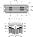
- FIGS. 1A , 1B and 1C a perspective view, a cross-sectional view and an exploded perspective view of a secondary battery according to an embodiment of the present invention are illustrated.
- the secondary battery 100 may include a case 110, first and second electrode assemblies 120A and 120B, a cap plate 130, a first electrode terminal 140 and a second electrode terminal 150.
- the case 110 may be made of a conductive metal, such as aluminum, an aluminum alloy or nickel plated steel, and may be substantially shaped of a hexahedron having an opening through which the electrode assemblies 120A and 120B can be inserted into the case 110. While the opening is not shown in FIG. 1B because the case 110 and the cap plate 130 are assembled with each other, it may be a substantially opened part of a top portion of the case 110. Meanwhile, since the internal surface of the case 110 is insulated, the case 110 may be insulated from the first and second electrode assemblies 120A and 120B.
- the case 110 may also referred to as a can in some instances.
- the case 110 may include a first long side portion 111 having a relatively large area, a second long side portion 112 facing the first long side portion 111 and having a relatively large area, a first short side portion 113 connecting first ends of the first and second long side portions 111 and 112 and having a relatively small area, a second short side portion 114 facing the third short side portion 113, connecting second ends of the first and second long side portions 111 and 112 and having a relatively small area, and a bottom portion 115 connecting the first and second long side portions 111 and 112 and the first and second short side portions 113 and 114.
- the first electrode assembly 120A is assembled inside the case 110. Particularly, one surface of the first electrode assembly 120A is coupled to the case 110 in a state in which it is brought into close contact/contact with the first long side portion 111 of the case 110.
- the first electrode assembly 120A may be manufactured by winding or laminating a stacked structure including a first electrode plate 121, a separator 122, and a second electrode plate 123, which are thin plates or layers.
- the first electrode plate 121 may operate as a positive electrode and the second electrode plate 123 may operate as a negative electrode.
- polarities of the first electrode plate 121 and the second electrode plate 123 may be reversed.
- a first winding center 125A (or a first winding leading edge) where winding is started may be located at the center of the first electrode assembly 120A.
- the first electrode plate 121 may include a first current collector plate 121 a made of a metal foil or mesh including aluminum or an aluminum alloy, a first coating portion 121b having a first electrically active material, such as a transition metal oxide, on the first current collector plate 121a, a first non-coating portion (or a first uncoated portion) 121c on which the first electrically active material is not coated, and a first electrode first multi-tab 161 outwardly (or upwardly) extended from the first non-coating portion 121c and electrically connected to the first electrode terminal 140.
- a first current collector plate 121 a made of a metal foil or mesh including aluminum or an aluminum alloy
- a first coating portion 121b having a first electrically active material, such as a transition metal oxide, on the first current collector plate 121a
- a first non-coating portion (or a first uncoated portion) 121c on which the first electrically active material is not coated
- a first electrode first multi-tab 161 outwardly
- the first electrode first multi-tab 161 may become a passageway of the flow of current between the first electrode plate 121 and the first electrode terminal 140 and may include multiple first electrode first tabs arranged in a stacked type to be referred to as multi-tabs.
- the first electrode first multi-tab 161 may be provided such that the first non-coating portion 121c is upwardly extended/protruded.
- the first electrode may be a positive electrode.
- the second electrode plate 123 may include a second current collector plate 123a made of a metal foil or mesh including copper, a copper alloy, nickel or a nickel alloy, a second coating portion 123b having a second electrically active material, such as graphite or carbon, on the second current collector plate 123a, a second non-coating portion (or a second uncoated portion) 123c on which the second electrically active material is not coated, and a second electrode first multi-tab 171 outwardly (or upwardly) extended from the second non-coating portion 123c and electrically connected to the second electrode terminal 150.
- a second current collector plate 123a made of a metal foil or mesh including copper, a copper alloy, nickel or a nickel alloy
- a second coating portion 123b having a second electrically active material, such as graphite or carbon
- the second electrode first multi-tab 171 may become a passageway of the flow of current between the second electrode plate 123 and the second electrode terminal 150 and may include multiple second electrode first tabs arranged in a stacked type to be referred to as multi-tabs.
- the second electrode first multi-tab 171 may be provided such that the second non-coating portion 123c is upwardly extended/protruded.
- the second electrode may be a negative electrode.
- the separator 122 may be positioned between the first electrode plate 121 and the second electrode plate 123 to prevent an electrical short circuit from occurring between the first electrode plate 121 and the second electrode plate 123 and to allow movement of lithium ions.
- the separator 122 may include polyethylene, polypropylene or a composite film of polyethylene and polypropylene.
- the material of the separator 122 is not limited to the specific materials listed herein.
- the separator 122 may not be provided.
- the second electrode assembly 120B may have substantially the same structure, type and/or material as those of the first electrode assembly 120A. Therefore, detailed descriptions of the second electrode assembly 120B will be omitted. However, one surface of the second electrode assembly 120B is coupled to the case 110 in a state in which it is brought into close contact/contact with the second long side portion 112 of the case 110. In addition, if the second electrode assembly 120B is manufactured in a winding type, a second winding center 125B (or a second winding leading edge) where winding is started may be located at the center of the second electrode assembly 120B.
- first and second electrode assemblies 120A and 120B include a boundary area where the first and second electrode assemblies 120A and 120B face each other inside the case 110 or a contact area 190 where the first and second electrode assemblies 120A and 120B are brought into close contact/contact with each other. That is to say, the first and second electrode assemblies 120A and 120B may be assembled inside the case 110 in a state in which they are brought into close contact/contact with each other.
- the second electrode assembly 120B may include a first electrode second multi-tab 162 outwardly (or upwardly) extended from the first electrode plate 121 and electrically connected to the first electrode terminal 140.
- the first electrode second multi-tab 162 may become a passageway of the flow of current between the first electrode plate 121 and the first electrode terminal 140 and may include multiple first electrode second tabs arranged in a stacked type to be referred to as multi-tabs.
- the first electrode second multi-tab 162 may be provided such that the first non-coating portion 121c is upwardly extended/protruded.
- the second electrode assembly 120B may include a second electrode second multi-tab 172 outwardly (or upwardly) extended from the second electrode plate 123 and electrically connected to the second electrode terminal 150.
- the second electrode second multi-tab 172 may become a passageway of the flow of current between the second electrode plate 123 and the second electrode terminal 150 and may include multiple second electrode second tabs arranged in a stacked type to be referred to as multi-tabs.
- the second electrode second multi-tab 172 may be provided such that the second non-coating portion 123c is upwardly extended/protruded.
- an axis of each of the first and second winding centers 125A and 125B of the first and second electrode assemblies 120A and 120B is substantially parallel or horizontal to a terminal axis of each of the first and second electrode terminals 140 and 150.
- the winding axis and the terminal axis may mean an up-and-down axis in FIGS.
- the expression "the winding axis and the terminal axis being substantially parallel or horizontal to each other” may mean that the winding axis and the terminal axis may not meet each other even if the winding axis and the terminal axis are extended or may meet each other when the winding axis and the terminal axis are extraordinarily extended.
- first and second multi-tabs 161 and 162 extended and bent a predetermined length are positioned between the first and second electrode assemblies 120A and 120B and the first electrode terminal 140
- first and second multi-tabs 171 and 172 extended and bent a predetermined length are positioned between the first and second electrode assemblies 120A and 120B and the second electrode terminal 150. That is to say, the first and second multi-tabs 161 and 162 located at one side may be extended and bent from top ends of the first and second electrode assemblies 120A and 120B toward the first electrode terminal 140 so as to be substantially symmetrical with each other to then be connected or welded to the first electrode terminal 140.
- first and second multi-tabs 171 and 172 located at the other side may also be extended and bent from the top ends of the first and second electrode assemblies 120A and 120B toward the second electrode terminal 150 so as to be substantially symmetrical with each other to then be connected or welded to the second electrode terminal 150.
- each of the first and second multi-tabs 161 and 162 located at one side may be the first non-coating portion 121c itself, which is a region of the first electrode plate 121, without a first active material coated thereon, or may be a separate member connected to the first non-coating portion 121c.
- the separate member may be made of one selected from the group consisting of aluminum, an aluminum alloy, nickel, a nickel alloy, copper, a copper alloy, and equivalents thereof.
- each of the first and second multi-tabs 171 and 172 located at the other side may be the second non-coating portion 123c itself, which is a region of the second electrode plate 123, without a second active material coated thereon, or may be a separate member connected to the second non-coating portion 123c.
- the separate member may be made of one selected from the group consisting of nickel, a nickel alloy, copper, a copper alloy, aluminum, an aluminum alloy, and equivalents thereof.
- first and second winding axes of the first and second electrode assemblies 120A and 120B and the terminal axes of the first and second electrode terminals 140 and 150 are substantially parallel or horizontal to each other, as described above, an electrolyte injection direction and the winding axes are also substantially parallel or horizontal to each other. Therefore, the first and second electrode assemblies 120A and 120B exhibit high electrolyte impregnation capability when an electrolyte is injected and internal gases are rapidly transferred to a safety vent 136 during over-charge, enabling the safety vent 136 to quickly operate.
- first and second multi-tabs 161/171 and 162/172 (or uncoated portions or separate members) of the first and second electrode assemblies 120A and 120B are extended and bent to be are directly electrically connected to the first and second electrode terminals 140 and 150, which shortens electrical paths, thereby reducing internal resistance of the secondary battery 100 while reducing the number of components of the secondary battery 100.
- first and second multi-tabs 161/171 and 162/172 (or uncoated portions or separate members) of the first and second electrode assemblies 120A and 120B are directly electrically connected to first and second electrode terminals 140 and 150 while being symmetrical with each other, unnecessary electrical short circuits between the first and second multi-tabs 161/171 and 162/172 and regions having polarities opposite to the first and second multi-tabs 161/171 or 162/172 (e.g., the case, cap plate and/or predetermined portions of the first and second electrode assemblies 120A and 120B can be prevented.
- insulation levels of the first and second multi-tabs 161/171 and 162/172 can be improved by the symmetrical structure of the first and second multi-tabsl 61/171 and 162/172.
- the first and second electrode assemblies 120A and 120B may be accommodated in the case 110 together with an electrolyte.
- the electrolyte may include an organic solvent, such as ethylene carbonate (EC), propylene carbonate (PC), diethyl carbonate (DEC), ethylmethyl carbonate (EMC), or dimethyl carbonate (DMC), and a lithium salt such as LiPF 6 or LiBF 4 .
- the electrolyte may be in a liquid, sold or gel phase.
- the cap plate 130 may be substantially shaped of a rectangle having lengths and widths and may be coupled to the case 110. That is to say, the cap plate 130 may seal an opening of the case 110 and may be made of the same material as the case 110.
- the cap plate 130 may be coupled to the case 110 by laser and/or ultrasonic welding.
- the cap plate 130 may also be referred to as a cap assembly in some instances.
- the cap plate 130 may include a plug 134 closing an electrolyte injection hole, and a safety vent 136 clogging a vent hole.
- the safety vent 136 may include a notch configured to be easily opened at a preset pressure.
- the first electrode terminal 140 may include a first electrode terminal plate 141 positioned on a top surface of the cap plate 130, a first upper insulation plate 142 positioned between the first electrode terminal plate 141 and the cap plate 130, a first lower insulation plate 143 positioned on a bottom surface of the cap plate 130, a first current collector plate 144 positioned on a bottom surface of the first lower insulation plate 143, and a first electrode terminal pillar 145 electrically connecting the first electrode terminal plate 141 and the first current collector plate 144.
- the secondary battery 100 may further include a first seal insulation gasket 146 insulating the cap plate 130 and the first electrode terminal pillar 145 from each other.
- first and second multi-tabs 161 and 162 of the first and second electrode assemblies 120A and 120B may be electrically connected to the first current collector plate 144 of the first electrode terminal 140 so as to be symmetrical with each other.
- the second electrode terminal 150 may include a second electrode terminal plate 151 positioned on the top surface of the cap plate 130, a second upper insulation plate 152 positioned between the second electrode terminal plate 151 and the cap plate 130, a second lower insulation plate 153 positioned on the bottom surface of the cap plate 130, a second current collector plate 154 positioned on a bottom surface of the second lower insulation plate 153, and a second electrode terminal pillar 145 electrically connecting the second electrode terminal plate 151 and the second current collector plate 154.
- the secondary battery 100 may further include a second seal insulation gasket 156 insulating the cap plate 130 and the second electrode terminal pillar 155 from each other.
- first and second multi-tabs 171 and 172 of the first and second electrode assemblies 120A and 120B may be electrically connected to the second current collector plate 154 of the second electrode terminal 150 so as to be symmetrical with each other.
- an insulation plate 180 is further positioned between each of the first and second electrode assemblies 120A and 120B, the first and second multi-tabs 161/171 and 162/172 and the first and second electrode terminals 140 and 150, thereby preventing the first and second multi-tabs 161/171 or 162/172 and regions having polarities opposite to the first and second multi-tabs 161/171 or 162/172 (e.g., the case, the cap plate and/or the predetermined regions of the first and second electrode assemblies) from being electrically short-circuited to each other.
- the insulation plate 180 may be made of, for example, but not limited to, a super engineering plastic, such as polyphenylene sulfide (PPS), having excellent dimension stability and maintaining a high strength and stiffness up to approximately 220°C.
- PPS polyphenylene sulfide
- the first and second multi-tabs 161/171 and 162/172 of the first and second electrode assemblies 120A and 120B are configured such that they are extended and bent to be symmetrical with each other with respect to the boundary area (or contact area) 190 between the first and second electrode terminals 140 and 150 or the first and second electrode assemblies 120A and 120B), thereby preventing the first and second multi-tabs 161/171 or 162/172 and the regions having polarities opposite to the first and second multi-tabs 161/171 or 162/172 (e.g., the case 110, the cap plate 130 and/or the predetermined regions of the first and second electrode assemblies 120A and 120B) from being electrically short-circuited to each other.0
- first and second multi-tabs 161/171 and 162/172 are configured to be symmetrical with each other with respect to the boundary area 190 between the first and second electrode terminals 140 and 150 or the first and second electrode assemblies 120A and 120B, a probability of electrical short circuits occurring between the first and second multi-tabs 161/171 and 162/172 and the case 110, the cap plate 130 and/or the predetermined regions of the first and second electrode assemblies 120A and 120B having polarities opposite to the first and second multi-tabs 161/171 or 162/172, may be increased.
- the probability of occurrence of such electrical short circuits can be reduced.
- a probability of electrical short circuits occurring between the positive electrode first and second multi-tabs 161 and 162 configured to be symmetrical with each other and the negative electrode non-coating portions 123c of the first and second electrode assemblies 120A and 120B is smaller than a probability of electrical short circuits occurring between positive electrode first and second multi-tabs configured to be asymmetrical with each other and negative electrode non-coating portions of first and second electrode assemblies, but aspects of the present invention are not limited thereto.
- a probability of electrical short circuits occurring between the negative electrode first and second multi-tabs 171 and 172 configured to be symmetrical with each other and the positive electrode non-coating portions 121c of the first and second electrode assemblies 120A and 120B is smaller than a probability of electrical short circuits occurring between negative electrode first and second multi-tabs configured to be asymmetrical with each other and positive electrode non-coating portions of first and second electrode assemblies, but aspects of the present invention are not limited thereto.
- the first and second multi-tabs 161/171 and 162/172 of the first and second electrode assemblies 120A and 120B are configured to be symmetrical with each other, the number or area of management regions for preventing electrical short circuits between the first and second multi-tabs 161/171 or 162/172 and the regions having opposite polarities, that is, the case 110, the cap plate 130 and/or the predetermined regions of the first and second electrode assemblies 120A and 120B, may be reduced. Accordingly, the electrical short circuits between the first and second multi-tabs 161/171 and 162/172 and the regions having the opposite polarities can be easily prevented.
- first and second multi-tabs 161/171 and 162/172 of the first and second electrode assemblies 120A and 120B are configured to be asymmetrical with each other, the number or area of management regions for preventing electrical short circuits between the first and second multi-tabs 161/171 or 162/172 and the regions having opposite polarities, may be increased. Accordingly, it is difficult to prevent the electrical short circuits between the first and second multi-tabs161/171 and 162/172 and the regions having the opposite polarities.
- FIGS. 2A and 2B a plan view and a partial cross-sectional view of first and second electrode assemblies in a secondary battery having a structure for suppressing multi-tab short circuits according to an embodiment of the present invention are illustrated.
- the first electrode assembly 120A may include a first winding center 125A (or a first winding leading edge) where winding is started, and the second electrode assembly 120B may also include a second winding center 125B (or a second winding leading edge) where winding is started.
- the first and second electrode assemblies 120A and 120B may have a boundary area (or contact area) 190) therebetween.
- outer regions of the first and second electrode assemblies 120A and 120B may mean regions spaced apart from the boundary area 190 between the first and second electrode assemblies 120A and 120B and closer to the first and second long side portions 111 or 112 of the case 110
- inner regions of the first and second electrode assemblies 120A and 120B may mean regions spaced apart from the first and second long side portions 111 or 112 of the case 110 and closer to the boundary area 190 between the first and second electrode assemblies 120A and 120B.
- the outer regions of the first and second electrode assemblies 120A and 120B may mean regions from the first and second winding centers 125A or 125B to the first and second long side portions 111 or 112 of the case 110, and the inner regions of the first and second electrode assemblies 120A and 120B may mean regions from the first and second winding centers 125A or 125B to the boundary area 190 between the first and second electrode assemblies 120A and 120B. It should be understood that definitions of the outer and inner regions of the first and second electrode assemblies 120A and 120B can be commonly applied to all embodiments of the present invention.
- the first and second electrode assemblies 120A and 120B may include the first and second multi-tabs 161/162 or 171/172 located at their outer regions so as to be symmetrical with each other with respect to the boundary area 190.
- the first multi-tabs 161 and 171 may be located only at, for example, but not limited to, the outer region of the first electrode assembly 120A. That is to say, the first multi-tabs 161 and 171 may not be located at the inner regions of the first electrode assembly 120A.
- the second multi-tabs 162 and 172 may also be located only at the outer regions of the second electrode assembly 120B.
- the second multi-tabs 162 and 172 may not be located at the inner regions of the second electrode assembly 120B. More specifically, as shown in FIG. 2A , the first multi-tabs 161 and 171 may be located only at roughly upper regions of the first winding center 125A in the first electrode assembly 120A (i.e., regions adjacent to the first long side portion 111 of the case 110), and the second multi-tabs 162 and 172 may be located only at roughly lower regions of the second winding center 125B in the second electrode assembly 120B (i.e., regions adjacent to the second long side portion 112 of the case 110). Therefore, the maximum distance between the first and second multi-tabs 161/162 or 171/172 may be equal to or slightly smaller than the maximum overall width (or thickness) of the first and second electrode assemblies 120A and 120B.
- the first and second electrode assemblies 120A and 120B may include the first and second multi-tabs 161 and 162 extended and bent from the outer regions so as to be symmetrical with each other with respect to the boundary area 190 or the electrode terminal 140.
- the first and second multi-tabs 161 and 162 may be extended and bent from, for example, but not limited to, the outer regions of the first and second electrode assemblies 120A and 120B to the electrode terminal 140 so as to be symmetrical with each other with respect to the boundary area 190.
- first and second multi-tabs 161 and 162 may be extended and bent to the electrode terminal 140 from regions closer to the case 110 (i.e., the first long side portion or the second long side portion) than to the boundary area 190 between the first and second electrode assemblies 120A and 120B, respectively.
- first and second multi-tabs 161 and 162 may include first regions 161a and 162a extended from the outer regions of the first and second electrode assemblies 120A and 120B, second regions 161b and 162b extended from the first regions 161a and 162a to be adjacent to the case 110, and third regions 161c and 162c bent from the second regions 161b and 162b to be electrically connected to the electrode terminal 140, respectively.
- first regions 161a and 162a get closer from the case 110 (i.e., the first long side portion or the second long side portion) to the boundary area 190 between the first and second electrode assemblies 120A and 120B, bending angles of the first regions 161a and 162a are more increased.
- the second regions 161b and 162b may be substantially parallel with a longitudinal direction of the case 110 (i.e., the first long side portion or the second long side portion).
- the third regions 161c and 162c may be connected to the electrode terminal 140 while being bent roughly at right angle from the second regions 161b and 162b.
- the insulation plate 180 is further located between the first and second electrode assemblies 120A and 120B and the first and second multi-tabs 161 and 162, and the electrode terminal 140, electrical short circuits may not occur between the first and second multi-tabs 161 and 162, and the case, the cap plate and/or the predetermined regions of the first and second electrode assemblies, which have polarities opposite to the first and second multi-tabs 161 and 162.
- the insulation plate 180 is placed roughly on the separator 122 of each of the first and second electrode assemblies 120A and 120B.
- the first and second multi-tabs 161 and 162 are extended and bent from the outer regions of the first and second electrode assemblies 120A and 120B to the electrode terminal 140 so as to be symmetrical with each other with respect to the electrode terminal 140 or the boundary area 190 between the first and second electrode assemblies 120A and 120B, thereby suppressing electrical short circuits between the first and second multi-tabs 161 and 162 and the regions having polarities opposite thereto (e.g., the case, the cap plate and/or the predetermined regions of the first and second electrode assemblies).
- FIGS. 3A and 3B a plan view and a partial cross-sectional view of first and second electrode assemblies in a secondary battery having a structure for suppressing multi-tab short circuits according to another embodiment of the present invention are illustrated.
- the first and second electrode assemblies 120A and 120B may include first and second multi-tabs 261/262 or 271/272 located at their inner regions so as to be symmetrical with each other with respect to the boundary area 190 between the first and second electrode assemblies 120A and 120B.
- the first multi-tabs 261 and 271 may be located only at, for example, but not limited to, the inner regions of the first electrode assembly 120A. That is to say, the first multi-tabs 261 and 271 may not be located at the outer regions of the first electrode assembly 120A.
- the second multi-tabs 262 and 272 may also be located only at the inner regions of the second electrode assembly 120B.
- the second multi-tabs 262 and 272 may not be located at the outer regions of the second electrode assembly 120B. More specifically, as shown in FIG. 3A , the first multi-tabs 261 and 271 may be located only at roughly lower regions of the first winding center 125A in the first electrode assembly 120A (i.e., regions adjacent to the boundary area 190), and the second multi-tabs 262 and 272 may be located only at roughly upper regions of the second winding center 125B in the second electrode assembly 120B (i.e., regions adjacent to the boundary area 190). Therefore, the maximum distance between the first and second multi-tabs 261/262 or 271/272 may be equal to or slightly greater than the minimum distance between the first and second electrode assemblies 120A and 120B.
- the first and second electrode assemblies 120A and 120B may include the first and second multi-tabs 261 and 262 extended and bent from the inner regions so as to be symmetrical with each other with respect to the boundary area 190 between first and second electrode assemblies 120A and 120B or the electrode terminal 140.
- the first and second multi-tabs261 and 262 may be extended and bent, for example, but not limited to, from the inner regions of the first and second electrode assemblies 120A and 120B to the electrode terminal 140 so as to be symmetrical with each other, respectively.
- first and second multi-tabs 261 and 262 may be extended and bent to the electrode terminal 140 from regions closer to the boundary area 190 between the first and second electrode assemblies 120A and 120B than to the first long side portion 111 or the second long side portion 112 of the case 110.
- first and second multi-tabs 261 and 262 may include first regions 261a and 262a extended from the inner regions of the first and second electrode assemblies 120A and 120B, second regions 261b and 262b extended from the first regions 261a and 262a to be adjacent to the case 110, and third regions 261c and 262c bent from the second regions 261b and 262b to be electrically connected to the electrode terminal 140, respectively.
- first regions 261a and 262a get closer from the case 110 to the boundary area 190 between the first and second electrode assemblies 120A and 120B, bending angles of the first regions 261a and 262a are more increased.
- the second regions 261b and 262b may be substantially parallel with a longitudinal direction of the case 110.
- the third regions 261c and 262c may be connected to the electrode terminal 140 while being bent roughly at right angle from the second regions 261b and 262b.
- the insulation plate 180 is further located between the first and second electrode assemblies 120A and 120B and the first and second multi-tabs 261 and 262, and the electrode terminal 140, electrical short circuits may not occur between the first and second multi-tabs 261 and 262, and the case, the cap plate and/or the predetermined regions of the first and second electrode assemblies, which have polarities opposite to the first and second multi-tabs 261 and 262.
- the insulation plate 180 is placed roughly on the first regions 261a and 262a of the first and second multi-tabs 261 and 262.
- the first and second multi-tabs 261 and 262 are extended and bent from the inner regions of the first and second electrode assemblies 120A and 120B to the electrode terminal 140 so as to be symmetrical with each other with respect to the electrode terminal 140 or the boundary area 190 between the first and second electrode assemblies 120A and 120B, thereby suppressing electrical short circuits between the first and second multi-tabs 261 and 262 and the regions having polarities opposite thereto (e.g., the case, the cap plate and/or the predetermined regions of the first and second electrode assemblies).
- FIGS. 4A and 4B a plan view and a perspective view of first and second electrode assemblies in a secondary battery having a structure for suppressing multi-tab short circuits according to another embodiment of the present invention are illustrated.
- first and second electrode assemblies 120A and 120B may include first and second multi-tabs (or outer multi-tabs) 361 and 362 located at their outer regions and first and second multi-tabs (or inner multi-tabs) 371 and 372 located at their inner regions.
- the first and second multi-tabs 361 and 362 located roughly in the left sides of the first and second electrode assemblies 120A and 120B may be symmetrical with outer regions (i.e., regions each adjacent to a first long side portion or a second long side portion) of the first and second electrode assemblies 120A and 120B, and the first and second multi-tabs 371 and 372 located roughly in the right sides of the first and second electrode assemblies 120A and 120B may be symmetrical with inner regions (i.e., regions each adjacent to the boundary area) of the first and second electrode assemblies 120A and 120B.
- the left-side first and second multi-tabs 361 and 362 may be positive electrode tabs
- the right-side first and second multi-tabs 371 and 372 may be negative electrode tabs.
- the left-side first multi-tab 361 (positive electrode) may be located at the outer region of the first electrode assembly 120A, and the right-side first multi-tab 371 (negative electrode) may be located at the inner region of the first electrode assembly 120A.
- the left-side first multi-tab 362 (positive electrode) may be located at the outer region of the second electrode assembly 120B, and the right-side first multi-tab 372 (negative electrode) may be located at the inner region of the second electrode assembly 120B.
- first and second multi-tabs 361 and 362 of the first and second electrode assemblies 120A and 120B may be symmetrical with each other, and the left-side first multi-tab 361 (positive electrode) and the right-side first multi-tab 371 (negative electrode) of the first electrode assembly 120A are extended and bent to be symmetrical with each other to then be coupled to the first and second electrode terminals 140 and 150, respectively.
- first and second multi-tabs 371 and 372 of the first and second electrode assemblies 120A and 120B may be symmetrical with each other, and the left-side second multi-tab 362 (positive electrode) and the right-side second multi-tab 372 (negative electrode) of the second electrode assembly 120B are extended and bent to be symmetrical with each other to then be coupled to the first and second electrode terminals 140 and 150, respectively.
- the first electrode assembly 120A is coupled to the first and second electrode terminals 140 and 150, respectively, in a state in which the positive electrode first multi-tab 361 and the negative electrode first multi-tab 371 are symmetrical with each other
- the second electrode assembly 120B is coupled to the first and second electrode terminals 140 and 150, respectively, in a state in which the positive electrode second multi-tab 362 and the negative electrode second multi-tab 372 are symmetrical with each other, thereby improving coupling strength, coupling stiffness and coupling reliability between the first and second electrode assemblies 120A and 120B and the first and second electrode terminals 140 and 150.
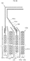
- FIGS. 5A and 5B enlarged cross-sectional views illustrating states before and after bending multi-tabs according to an embodiment of the present invention are illustrated.
- FIG. 5A shows a state before bending the multi-tabs 161 of the electrode assembly 120A.
- the multi-tabs 161 are directly extended in forms of straight lines.
- FIG. 5B shows a state after bending the multi-tabs 161 of the electrode assembly 120A by connecting the multi-tabs 161 of the electrode assembly 120A to the electrode terminal 140.
- the multi-tabs 161 are bent in a roughly L-shaped configuration.
- the electrode assembly 120A may include the first electrode plate 121, the separator 122 and the second electrode plate 123, as described above.
- the first electrode plate 121 may have, for example, but not limited to, a positive polarity, and may include a first current collector plate 121a having a substantially planar first surface 121d and a substantially planar second surface 121e opposite to the first surface 121d.
- the first electrode plate 121 may have a first electrically active material layer 121b coated on the first surface 121d and/or the second surface 121e of the first current collector plate 121a.
- the multi-tabs 161 may have, for example, but not limited to, a structure in which the first current collector plate 121a or the non-coating portion 121c (see FIG. 1C ) is upwardly extended to an exterior side of the first electrically active material layer 121b of the first electrode plate 121. Therefore, the multi-tab 161 may also have a substantially planar first surface 161d and a substantially planar second surface 161e opposite to the first surface 161d.
- first surface 121d of the first current collector plate 121a and the first surface 161d of the multi-tab 161 may be substantially coplanar, and the second surface 121e of the first current collector plate 121a and the second surface 161e of the multi-tab 161 may also be substantially coplanar.
- first current collector plate 121a and the multi-tabs 161 may have substantially the same thickness.
- the multi-tabs 161 may also be provided by attaching a separate member to the first current collector plate 121a or the non-coating portion 121c outwardly extended from the first electrically active material layer 121b.
- the separator 122 is positioned between the first electrode plate 121 and the second electrode plate 123.
- a length (or height) of the separator 122 may be greater than a length (or height) of the first electrode plate 121 and/or the second electrode plate 123. That is to say, a top end of the separator 122 may be positioned higher than top ends of the first electrode plate 121 and/or the second electrode plate 123.
- the second electrode plate 123 may have, for example, but not limited to, a negative polarity.
- the second electrode plate 123 is located at one side of the separator 122 and may include a second current collector plate 123a having a substantially planar first surface 123d and a substantially planar second surface 123e opposite to the first surface 123d, and a second electrically active material layer 123b coated on the first surface 123d and/or the second surface 123e of the second current collector plate 123a.
- a safety function layer (SFL) 123f allowing lithium ions to pass while blocking migration electrons may be further located on a surface of the second electrically active material layer 123b.
- the SFL 123f may be made of, for example, but not limited to, an inorganic material, such as ceramic, and may suppress decomposition of electrolyte by blocking the electron migration.
- the length (or height) of the second electrode plate 123 may be greater than that of the first electrode plate 121.
- excessive lithium ions or metallic ions may not exist inside the electrode assembly 120A (particularly, on the surface of the second electrically active material layer).
- the length (or height) of the separator 122 is largest, and the length (or height) of the first electrode plate 121, exclusive of the multi-tab 161, is smallest.
- the separator 122 is positioned between the multi-tab 161 and the second electrode plate 123, the multi-tab 161 can be prevented from being directly electrically short-circuited to the second electrode plate 123 (e.g., the second current collector plate 123a or the second electrically active material layer 123b) even if the multi-tab 161 is bent to be connected to the electrode terminal 140.
- the second electrode plate 123 e.g., the second current collector plate 123a or the second electrically active material layer 123b
- insulating layers 280 may be coated on surfaces of the multi-tabs 161. That is to say, the insulating layers 280 may be coated on the first surface 161d and/or the second surface 161e of the multi-tab 161. The insulating layers 280 may be coated on the first surface 161d and/or the second surface 161e while being in contact with the first electrically active material layer 121b. Moreover, a topmost height of each of the insulating layers 280 may be equal to, for example, a topmost height of each of the separators 122.
- the multi-tabs 161 may be at risk of being brought into direct contact with the second electrode plate 123 (e.g., the second current collector plate 123a, the second electrically active material layer 123b, etc.) when they are bent.
- the insulation level of the multi-tab 161 is increased, but the insulating efficiency between the multi-tabs 161 and the second electrode plate 123 may not be improved any more.
- a thickness of the insulating layer 280 may be smaller than a thickness of the first electrically active material layer 121b.
- the thickness of the first electrically active material layer 121b may be in the range from, for example, but not limited to, about 100 ⁇ m to about 600 ⁇ m, and the thickness of the insulating layer 280 may be in the range from about 0.1 ⁇ m to about 100 ⁇ m, preferably from about 1 ⁇ m to about 50 ⁇ m, more preferably from about 3 ⁇ m to about 8 ⁇ m.
- the overall thickness of the electrode assembly 120A may be increased as much as the thickness of the insulating layer 280, and the multi-tabs 161 may not be properly bent. Moreover, when the multi-tabs 161 are bent, the insulating layers 280 may be separated away from the multi-tabs 161.
- a double insulating structure including the insulating layer 280 and the separator 122 may be positioned between the multi-tabs 161 and the second electrode plate 123, thereby preventing electrical short circuits between the multi-tabs 161 and the second electrode plate 123, that is, increasing the insulation level of the multi-tabs 161.
- a triple insulating structure including the insulating layer 280, the separator 122 and the SFL 123f may be positioned between the multi-tabs 161 and the second electrode plate 123, thereby more efficiently preventing electrical short circuits between the multi-tabs 161 and the second electrode plate 123. That is to say, the insulation level of the multi-tabs 161 may be further increased.
- the insulating layer 280 may be made of, for example, but not limited to, an organic material, an inorganic material, or an organic-inorganic composite (or hybrid) material, using one or a combination of processes selected from the group consisting of inkjet printing, coating, dip coating, doctor blade, dry dipping, hydro thermal reaction, sol-gel, spraying, aerosol deposition, chemical vapor deposition, physical vapor deposition, roll to roll, casting, an ion beam deposition, and equivalents thereof.
- the organic material may include, for example, but not limited to, one or a mixture of materials selected from the group consisting of polyimide (PI), polyamideimide (PA), polyvinylidene fluoride (PVdF), polyurethane (PU), polyurea, polycarbonate (PC), polyethylene terephthalate (PET) polymethyl methacrylate (PMMA), polybutylene terephthalate (PBT), polyvinyl alcohol (PVA), polyvinyl butyral (PVB) and equivalents thereof.
- PI polyimide
- PA polyamideimide
- PVdF polyvinylidene fluoride
- PU polyurethane
- PC polycarbonate
- PET polyethylene terephthalate
- PMMA polymethyl methacrylate
- PBT polybutylene terephthalate
- PVVA polyvinyl alcohol
- PVB polyvinyl butyral
- the inorganic may include, for example, but not limited to, one or a mixture of two materials selected from the group consisting of alpha alumina ( ⁇ -Al2O3), alumina (Al2O3), aluminum hydroxide (Al(OH)3, bohemite), lead zirconate titanate (Pb(Zr,Ti)O3(PZT)), titanium dioxide (TiO 2 ), zirconia (ZrO 2 ), yttria (Y 2 O 3 ), yttria stabilized zirconia (YSZ), dysprocia (Dy 2 O 3 ), gadolinia (Gd 2 O 3 ), ceria (CeO 2 ), gadolinia doped ceria (GDC), magnesia (MgO), barium titanate (BaTiO 3 ), nickel manganite (NiMn 2 O 4 ), potassium sodium niobate (KNaNbO 3 ), bismuth potassium titanate (B
- the average particle diameter of the inorganic material may be in the range from, for example, but not limited to, about 0.1 ⁇ m to about 100 ⁇ m, preferably from about 0.3 ⁇ m to about 10 ⁇ m, more preferably from about 0.5 ⁇ m to about 5 ⁇ m.
- the multi-tabs 161 are bent in a roughly L-shaped configuration. Or after the multi-tabs 161 are connected to the electrode terminal 140, the multi-tabs 161 are bent in a roughly L-shaped configuration.
- the multi-tabs 161 are bent while being in close contact with each other, not only the multi-tabs 161 but also the separator 122 and/or the second electrode plate 123 are bent at a predetermined angle.
- the separators 122 are bent with the multi-tabs 161, as shown in FIG. 5B .
- the insulating layers 280 are coated on the surfaces of the multi-tabs 161, as described above, the insulating layers 280 are also bent.
- the multi-tabs 161 and the insulating layers 280 are brought into contact with/close contact with the separator 122 while being bent.
- FIG. 5B shows that the multi-tabs 161, the separator 122 and the second electrode plate 123 are spaced apart from one another, they may be substantially brought into contact/close contact with one another.
- the electrical short circuits can be prevented from occurring between the multi-tabs 161 and the and the second electrode plate 123 (i.e., the second current collector plate 123a and/or the second electrically active material layer 123b) by the double insulating structure including the insulating layer 280 and the separator 122, or the triple insulating structure including the insulating layer 280, the separator 122 and the SFL 123f, positioned between the multi-tab 161 and the second electrode plate 123.
- the insulating layer 280 that is the same as described may be located on the surface of the second current collector plate 123a exposed through the second electrically active material layer 123b. Therefore, a triple insulating structure including the insulating layer 280, the separator 122 and the insulating layer 280 may be provided between the multi-tabs 161 and the second current collector plate 123a, thereby improving the insulating efficiency between the multi-tabs 161 and the second current collector plate 123a.
- the mutual relationships, materials, types and configurations of the insulating layers 280, the first electrode plate 121, the separators 122 and the second electrode plate 123 located on the multi-tabs 161 can be commonly applied to all embodiments of the present invention.
- FIGS. 6A and 6B are enlarged cross-sectional views illustrating states before and after bending multi-tabs according to another embodiment of the present invention.
- insulating layers 380 formed on surfaces of the multi-tab 161 may be spaced apart a predetermined distance apart from the first electrically active material layer 121b. That is to say, the insulating layers 380 may not be necessarily brought into direct contact with the first electrically active material layer 121b but may be located only on areas needed to be insulated.
- the insulating layers 380 may be located only at predetermined areas of the multi-tabs 161 facing (corresponding to) a top end of the second electrode plate 123 spaced apart from the first electrically active material layer 121b. That is to say, the insulating layers 380 may be located only at predetermined areas of the multi-tabs 161, where the multi-tabs 161 are not electrically short-circuited to the second electrode plate 123 even if the separator 122 is punched by bent regions of the multi-tabs 161 at the time of bending the multi-tabs 161.
- the insulating layers 380 may be spaced, for example, but not limited to, about 0.1 mm to about 3 mm from the first electrically active material layer 121b.
- the manufacturing process of the multi-tabs 161 can be facilitated. That is to say, the insulating layers 380 are located on a non-coating portion of an electrode plate, followed by performing a notching process using a laser beam or a mold, thereby providing the multi-tabs 161. As described above, since the insulating layers 380 are located only at the predetermined areas of the multi-tabs 161, electrical/mechanical loads during the notching process using a laser beam or a mold can be reduced, thereby facilitating the manufacturing process.
- FIGS. 7A and 7B are enlarged cross-sectional views of multi-tabs according to another embodiment of the present invention.
- each of the multi-tabs 161 may have a substantially planar first surface 161d, a substantially planar second surface 161e opposite to the first surface 161d, a third surface 161f connecting first ends of the first and second surfaces 161d and 161e, and a fourth surface 161g connecting second ends of the first and second surfaces 161d and 161e and opposite to the third surface 161f.
- the insulating layers 280 may be located only on the first and second surfaces 161d and 161e, which are relatively wide surfaces. That is to say, the third and fourth surfaces 161f and 161g of the multi-tab 161 may be exposed.
- the insulating layers 280 are located on first and second surfaces of the non-coating portion, and the multi-tabs 161 are then formed by performing the notching (or cutting) process using a laser beam or a mold. Therefore, as described above, the insulating layers 280 may not be located on the third and fourth surfaces 161f and 161g of the multi-tab 161 but may be exposed. That is to say, one surface of each of the insulating layers 280 may be coplanar with the third surface 161f of the multi-tab 161, and the other surface of the insulating layer 280 may be coplanar with the fourth surface 161g of the multi-tab 161.
- the insulating layers 280 may be located not only on the first and second surfaces 161d and 161e, which are relatively wide surfaces, but also on the third and fourth surfaces 161f and 161g, which are relatively narrow surfaces. That is to say, none of the first, second, third and fourth surfaces 161d, 161e, 161f and 161g of the multi-tab 161 may be exposed through the insulating layers 280.
- the insulating layers 280 are located on the first and second surfaces of the non-coating portion, and the multi-tabs 161 are then formed by performing the notching (or cutting) process using a laser beam or a mold. Therefore, as described above, the insulating layers 280 may be located not only on the first and second surfaces 161d and 161e but also on the third and fourth surfaces 161f and 161g of the multi-tab 161.
- insulating layer 280 located on the first surface 161d or the second surface 161e is pushed to the third and fourth surfaces 161f and 161g, so that the third and fourth surfaces 161f and 161g of the multi-tab 161 are covered by the insulating layer 280.
- the insulating layers 280 located on the third and fourth surfaces 161f and 161g of the multi-tab 161 can also prevent electrical short circuits from occurring between the third and fourth surfaces 161f and 161g and the second electrode plate 123 through the above-described process.
- the insulating layers 280 are formed on the surfaces of the multi-tabs 161, it should be understood by one skilled in the art that the insulating layers 280 are located on the surfaces of the first and second multi-tabs 161/171 and/or 162/172. Moreover, it should be understood by one skilled in the art that these features can be commonly applied to all embodiments of the present invention.
- FIGS. 8A to 8C schematic views illustrating a manufacturing method of a secondary battery 100 having a structure for suppressing multi-tab short circuits according to an embodiment of the present invention are illustrated.
- the first electrode first multi-tab 161 and the second electrode first multi-tab 171 of the first electrode assembly 120A are welded to the first electrode terminal 140, that is, the first current collector plate 144, and the second electrode terminal 150, that is, the second current collector plate 154, provided in the cap plate 130, and the first electrode second multi-tab 162 and the second electrode second multi-tab 172 of the second electrode assembly 120B are also welded to the first electrode terminal 140 and the second electrode terminal 150, respectively.
- the first electrode first multi-tab 161 and the second electrode first multi-tab 171 of the first electrode assembly 120A, and the first electrode second multi-tab 162 and the second electrode second multi-tab 172 of the second electrode assembly 120B have yet to be bent.
- the insulation plate 180 is placed on the cap plate 130. That is to say, the insulation plate 180 is placed on the first electrode first multi-tab 161 and the first electrode second multi-tab 162, which are positioned on the first current collector plate 144, and the second electrode first multi-tab 171 and second electrode second multi-tab 172, which are positioned on the second current collector plate 154.
- the first and second electrode assemblies 120A and 120B are bent roughly at right angle from the cap plate 130. Accordingly, the first and second multi-tabs 161 and 162 provided in the first and second electrode assemblies 120A and 120B are bent with the first regions 161a and162a, the second regions 161b and 162b and the third regions 161c and 162c.
- the insulation plate 180 may be substantially covered by the first and second electrode assemblies 120A and 120B, the first and second multi-tabs 161 and 162 and the cap plate 130.
- the first and second electrode assemblies 120A and 120B are brought into close contact with each other to be parallel with each other.
- the first and second electrode assemblies 120A and 120B being in close contact with each other are inserted into the case 110. That is to say, until the cap plate 130 closes the case 110, the first and second electrode assemblies 120A and 120B and the cap plate 130 are pushed into the case 110.
- the cap plate 130 is welded to the case 110 to then be fixed, and an electrolytic solution is inserted into the case 110 through an electrolyte injection hole.
- this process may be omitted in a case of a solid battery requiring no electrolytic solution.
- the first and second multi-tabs 161 and 162 are located only at outer regions (or inner regions) of the first and second electrode assemblies 120A and 120B, as the result of the bending process, the first and second multi-tabs 161 and 162 are bent so as to be symmetrical with each other. Therefore, it is possible to prevent electrical short circuits between the first and second multi-tabs 161 and 162, and the case, the cap plate and/or the first and second electrode assemblies, which have polarities opposite to the first and second multi-tabs 161 and 162 from occurring during or after the manufacture of the secondary battery 100.
- FIG. 9 a perspective view illustrating an example of a battery module using a secondary battery 100 having a structure for suppressing multi-tab short circuits according to an embodiment of the present invention is illustrated.
- multiple secondary batteries 100 are arranged in a line and multiple bus bars 510 are coupled to the multiple secondary batteries 100, thereby completing the battery module 1000.
- a first electrode terminal 140 of one of the multiple secondary batteries 100 and a second electrode terminal 150 of another adjacent secondary battery 100 may be welded to each other using the bus bar 510, thereby providing the battery module 1000 including the multiple secondary batteries 100 connected to one another in series.
- the bus bar 510 may be made of aluminum or an aluminum alloy, and a first terminal plate 131 of the first electrode terminal 140 and a second terminal plate 141 of the second electrode terminal 150 may also be made of aluminum or an aluminum alloy, thereby allowing the bus bar 510 to be easily welded to the first electrode terminal 140 and the second electrode terminal 150.
Landscapes
- Chemical & Material Sciences (AREA)
- Chemical Kinetics & Catalysis (AREA)
- Electrochemistry (AREA)
- General Chemical & Material Sciences (AREA)
- Engineering & Computer Science (AREA)
- Manufacturing & Machinery (AREA)
- Materials Engineering (AREA)
- Inorganic Chemistry (AREA)
- Composite Materials (AREA)
- Connection Of Batteries Or Terminals (AREA)
- Secondary Cells (AREA)
Applications Claiming Priority (2)
| Application Number | Priority Date | Filing Date | Title |
|---|---|---|---|
| KR1020170023768A KR102890540B1 (ko) | 2017-02-22 | 2017-02-22 | 멀티탭 쇼트 억제 구조를 갖는 이차 전지 |
| PCT/KR2018/001616 WO2018155845A2 (fr) | 2017-02-22 | 2018-02-06 | Batterie secondaire à structure de suppression de courts-circuits à languettes multiples |
Publications (3)
| Publication Number | Publication Date |
|---|---|
| EP3588621A2 true EP3588621A2 (fr) | 2020-01-01 |
| EP3588621A4 EP3588621A4 (fr) | 2020-11-18 |
| EP3588621B1 EP3588621B1 (fr) | 2023-05-03 |
Family
ID=63253355
Family Applications (1)
| Application Number | Title | Priority Date | Filing Date |
|---|---|---|---|
| EP18758276.2A Active EP3588621B1 (fr) | 2017-02-22 | 2018-02-06 | Batterie secondaire à structure de suppression de courts-circuits à languettes multiples |
Country Status (7)
| Country | Link |
|---|---|
| US (1) | US11380966B2 (fr) |
| EP (1) | EP3588621B1 (fr) |
| KR (2) | KR102890540B1 (fr) |
| CN (1) | CN110326134B (fr) |
| HU (1) | HUE062185T2 (fr) |
| PL (1) | PL3588621T3 (fr) |
| WO (1) | WO2018155845A2 (fr) |
Cited By (4)
| Publication number | Priority date | Publication date | Assignee | Title |
|---|---|---|---|---|
| CN114050230A (zh) * | 2021-11-12 | 2022-02-15 | 欣旺达电动汽车电池有限公司 | 极片、电芯、单体电池及电池包 |
| EP3910703A3 (fr) * | 2020-12-14 | 2022-03-16 | Dongguan Poweramp Technology Limited | Appareil électrochimique et appareil électronique |
| WO2023048787A1 (fr) * | 2021-09-21 | 2023-03-30 | Apple Inc. | Languette de batterie en boucle avec revêtement d'oxyde |
| EP4369465A1 (fr) * | 2022-11-11 | 2024-05-15 | Shenzhen Hithium Energy Storage Technology Co., Ltd. | Dispositif de stockage d'énergie et dispositif électronique |
Families Citing this family (13)
| Publication number | Priority date | Publication date | Assignee | Title |
|---|---|---|---|---|
| WO2020086835A1 (fr) * | 2018-10-24 | 2020-04-30 | Urban Electric Power Inc. | Couche barrière de protection pour batteries alcalines |
| KR102390657B1 (ko) | 2019-02-01 | 2022-04-26 | 주식회사 엘지에너지솔루션 | 절연필름을 포함하는 전극 조립체, 이의 제조방법, 및 이를 포함하는 리튬 이차전지 |
| KR102322714B1 (ko) | 2019-02-01 | 2021-11-08 | 주식회사 엘지에너지솔루션 | 절연층이 형성되어 있는 전극을 포함하는 스택형 전극조립체 및 이를 포함하는 리튬 이차전지 |
| KR102920238B1 (ko) | 2020-02-13 | 2026-02-02 | 삼성에스디아이 주식회사 | 집전 구조가 개선된 이차전지 |
| KR102917236B1 (ko) | 2020-02-27 | 2026-01-22 | 주식회사 엘지에너지솔루션 | 탭 상에 형성된 절연필름을 포함하는 전극 조립체, 이의 제조방법, 및 이를 포함하는 리튬 이차전지 |
| KR102852580B1 (ko) * | 2020-04-16 | 2025-08-28 | 주식회사 엘지에너지솔루션 | 이차 전지용 전극 |
| CN117099222A (zh) * | 2021-03-31 | 2023-11-21 | 松下知识产权经营株式会社 | 二次电池用电极、二次电池和二次电池用电极的制造方法 |
| WO2022209172A1 (fr) * | 2021-03-31 | 2022-10-06 | パナソニックIpマネジメント株式会社 | Électrode pour batterie secondaire, batterie secondaire et procédé de fabrication d'électrode pour batterie secondaire |
| JP7402204B2 (ja) * | 2021-07-20 | 2023-12-20 | プライムプラネットエナジー&ソリューションズ株式会社 | 電池および該電池の製造方法 |
| JP7522718B2 (ja) * | 2021-12-24 | 2024-07-25 | プライムプラネットエナジー&ソリューションズ株式会社 | 二次電池 |
| CN217507578U (zh) * | 2022-05-13 | 2022-09-27 | 宁德时代新能源科技股份有限公司 | 电极组件、电池单体、电池和用电设备 |
| KR102906817B1 (ko) | 2023-02-28 | 2026-01-05 | 팩토리얼 아이엔씨. | 돌출부를 구비하는 고체 전해질 및 이를 포함하는 전고체 배터리 |
| CN223651505U (zh) * | 2024-10-21 | 2025-12-09 | 株式会社Aesc日本 | 二次电池、电池组及电子装置 |
Family Cites Families (28)
| Publication number | Priority date | Publication date | Assignee | Title |
|---|---|---|---|---|
| KR100496305B1 (ko) | 2003-05-22 | 2005-06-17 | 삼성에스디아이 주식회사 | 파우치형 리튬 이차 전지와 이의 제조 방법 |
| WO2006093049A1 (fr) | 2005-03-02 | 2006-09-08 | Matsushita Electric Industrial Co., Ltd. | Pile secondaire aux ions de lithium et procédé de fabrication idoine |
| KR101225941B1 (ko) | 2006-11-30 | 2013-01-24 | 주식회사 엘지화학 | 표면 피복된 전극활물질 |
| US8628876B2 (en) | 2008-06-20 | 2014-01-14 | Samsung Sdi Co., Ltd. | Electrode assembly and lithium secondary battery with same |
| CN101609905A (zh) * | 2008-06-20 | 2009-12-23 | 三星Sdi株式会社 | 电池组件、该电池组件的电极组件及形成该电极组件的方法 |
| US8697272B2 (en) | 2009-09-01 | 2014-04-15 | Samsung Sdi Co., Ltd. | Secondary battery having an insulating member |
| US8802281B2 (en) | 2010-08-05 | 2014-08-12 | Samsung Sdi Co., Ltd. | Secondary battery with movement prevention tape |
| US8962179B2 (en) | 2010-08-30 | 2015-02-24 | Samsung Sdi Co., Ltd. | Secondary battery |
| JP2013016265A (ja) * | 2011-06-30 | 2013-01-24 | Sanyo Electric Co Ltd | 非水電解質二次電池 |
| JP2013030385A (ja) * | 2011-07-29 | 2013-02-07 | Panasonic Corp | ラミネート電池 |
| KR101275786B1 (ko) | 2011-08-23 | 2013-06-17 | 로베르트 보쉬 게엠베하 | 이차 전지 |
| WO2014017567A1 (fr) | 2012-07-24 | 2014-01-30 | 株式会社 東芝 | Accumulateur |
| KR101557302B1 (ko) | 2012-11-21 | 2015-10-05 | 주식회사 엘지화학 | 이종 분리막들을 포함하고 있는 전극조립체 및 이를 포함하는 이차전지 |
| KR101586530B1 (ko) * | 2013-03-11 | 2016-01-21 | 주식회사 엘지화학 | 양극 탭 상에 절연층을 포함하는 양극 및 이를 포함하는 이차 전지 |
| JP6219113B2 (ja) * | 2013-09-30 | 2017-10-25 | 株式会社東芝 | 二次電池 |
| KR101792572B1 (ko) * | 2014-02-20 | 2017-11-01 | 주식회사 엘지화학 | 절연물질이 코팅되어 있는 전극을 포함하는 전지셀 |
| WO2015129320A1 (fr) * | 2014-02-28 | 2015-09-03 | Necエナジーデバイス株式会社 | Électrode pour cellule secondaire, cellule secondaire et procédé de fabrication d'électrode pour cellule secondaire et de cellule secondaire |
| WO2015147066A1 (fr) * | 2014-03-25 | 2015-10-01 | 日本電気株式会社 | Batterie multicouche et son procédé de fabrication |
| DE102014207678A1 (de) * | 2014-04-24 | 2015-10-29 | Robert Bosch Gmbh | Batteriezelle und Verfahren zum Betrieb derselben |
| KR102201306B1 (ko) | 2014-06-17 | 2021-01-11 | 삼성에스디아이 주식회사 | 이차 전지 |
| WO2015198526A1 (fr) * | 2014-06-26 | 2015-12-30 | パナソニックIpマネジメント株式会社 | Batterie de type enroulé |
| KR102177506B1 (ko) * | 2014-07-30 | 2020-11-11 | 삼성에스디아이 주식회사 | 이차 전지 및 그 제조 방법 |
| KR20160059748A (ko) * | 2014-11-19 | 2016-05-27 | 삼성에스디아이 주식회사 | 전극 조립체 및 이를 포함하는 배터리 팩 |
| KR102279223B1 (ko) | 2014-11-25 | 2021-07-19 | 삼성에스디아이 주식회사 | 보호 테이프를 갖는 전극 조립체 및 이를 포함하는 이차 전지 |
| KR20160119383A (ko) | 2015-04-03 | 2016-10-13 | 삼성에스디아이 주식회사 | 전극 조립체 및 그 제조 방법과 이차 전지 |
| JP6510304B2 (ja) * | 2015-04-28 | 2019-05-08 | 株式会社日立ハイテクファインシステムズ | リチウムイオン二次電池の製造方法 |
| KR102425797B1 (ko) * | 2015-07-15 | 2022-07-28 | 삼성에스디아이 주식회사 | 이차 전지 |
| KR102448295B1 (ko) | 2015-07-16 | 2022-09-28 | 삼성에스디아이 주식회사 | 이차전지 |
-
2017
- 2017-02-22 KR KR1020170023768A patent/KR102890540B1/ko active Active
-
2018
- 2018-02-06 EP EP18758276.2A patent/EP3588621B1/fr active Active
- 2018-02-06 PL PL18758276.2T patent/PL3588621T3/pl unknown
- 2018-02-06 WO PCT/KR2018/001616 patent/WO2018155845A2/fr not_active Ceased
- 2018-02-06 US US16/485,743 patent/US11380966B2/en active Active
- 2018-02-06 CN CN201880013297.1A patent/CN110326134B/zh active Active
- 2018-02-06 HU HUE18758276A patent/HUE062185T2/hu unknown
-
2025
- 2025-11-20 KR KR1020250176489A patent/KR20250172493A/ko active Pending
Cited By (4)
| Publication number | Priority date | Publication date | Assignee | Title |
|---|---|---|---|---|
| EP3910703A3 (fr) * | 2020-12-14 | 2022-03-16 | Dongguan Poweramp Technology Limited | Appareil électrochimique et appareil électronique |
| WO2023048787A1 (fr) * | 2021-09-21 | 2023-03-30 | Apple Inc. | Languette de batterie en boucle avec revêtement d'oxyde |
| CN114050230A (zh) * | 2021-11-12 | 2022-02-15 | 欣旺达电动汽车电池有限公司 | 极片、电芯、单体电池及电池包 |
| EP4369465A1 (fr) * | 2022-11-11 | 2024-05-15 | Shenzhen Hithium Energy Storage Technology Co., Ltd. | Dispositif de stockage d'énergie et dispositif électronique |
Also Published As
| Publication number | Publication date |
|---|---|
| WO2018155845A2 (fr) | 2018-08-30 |
| CN110326134B (zh) | 2022-10-21 |
| CN110326134A (zh) | 2019-10-11 |
| US20190393474A1 (en) | 2019-12-26 |
| WO2018155845A3 (fr) | 2018-10-25 |
| KR102890540B1 (ko) | 2025-11-26 |
| KR20250172493A (ko) | 2025-12-09 |
| HUE062185T2 (hu) | 2023-09-28 |
| EP3588621A4 (fr) | 2020-11-18 |
| EP3588621B1 (fr) | 2023-05-03 |
| US11380966B2 (en) | 2022-07-05 |
| KR20180097085A (ko) | 2018-08-30 |
| PL3588621T3 (pl) | 2023-09-25 |
Similar Documents
| Publication | Publication Date | Title |
|---|---|---|
| EP3588621B1 (fr) | Batterie secondaire à structure de suppression de courts-circuits à languettes multiples | |
| EP3588617B1 (fr) | Batterie secondaire | |
| US11264681B2 (en) | Electrode assembly and secondary battery using the same | |
| CN110326131B (zh) | 具有对称的多重接线片的二次电池 | |
| US20220311057A1 (en) | Electrode assembly and secondary battery comprising same | |
| US10971783B2 (en) | Electrode assembly having improved heat stability | |
| CN115023839A (zh) | 具有改进的安全性的电池单元及其制造方法 | |
| US20250349999A1 (en) | Integrated terminal, secondary battery including the same, and method of manufacturing the same | |
| US20240396126A1 (en) | Secondary battery | |
| KR102629179B1 (ko) | 전극 조립체 및 이를 이용한 이차 전지 | |
| EP4742421A1 (fr) | Batterie et bloc-batterie comprenant celle-ci | |
| US20250337129A1 (en) | Secondary battery | |
| US20260081273A1 (en) | Secondary battery and method for manufacturing same | |
| EP4742427A1 (fr) | Batterie et bloc-batterie comprenant celle-ci | |
| US20250286246A1 (en) | Electrode assembly and method for manufacturing the same and rechargeable battery including the same | |
| KR20180120896A (ko) | 발수성 표면을 갖는 전극 단자를 포함하는 전지셀 |
Legal Events
| Date | Code | Title | Description |
|---|---|---|---|
| STAA | Information on the status of an ep patent application or granted ep patent |
Free format text: STATUS: THE INTERNATIONAL PUBLICATION HAS BEEN MADE |
|
| PUAI | Public reference made under article 153(3) epc to a published international application that has entered the european phase |
Free format text: ORIGINAL CODE: 0009012 |
|
| STAA | Information on the status of an ep patent application or granted ep patent |
Free format text: STATUS: REQUEST FOR EXAMINATION WAS MADE |
|
| 17P | Request for examination filed |
Effective date: 20190813 |
|
| AK | Designated contracting states |
Kind code of ref document: A2 Designated state(s): AL AT BE BG CH CY CZ DE DK EE ES FI FR GB GR HR HU IE IS IT LI LT LU LV MC MK MT NL NO PL PT RO RS SE SI SK SM TR |
|
| AX | Request for extension of the european patent |
Extension state: BA ME |
|
| DAV | Request for validation of the european patent (deleted) | ||
| DAX | Request for extension of the european patent (deleted) | ||
| A4 | Supplementary search report drawn up and despatched |
Effective date: 20201021 |
|
| RIC1 | Information provided on ipc code assigned before grant |
Ipc: H01M 10/0525 20100101ALI20201015BHEP Ipc: H01M 2/22 20060101ALI20201015BHEP Ipc: H01M 2/34 20060101AFI20201015BHEP Ipc: H01M 2/06 20060101ALI20201015BHEP Ipc: H01M 2/30 20060101ALI20201015BHEP Ipc: H01M 4/66 20060101ALI20201015BHEP |
|
| REG | Reference to a national code |
Ref country code: DE Ref legal event code: R079 Ref document number: 602018049232 Country of ref document: DE Free format text: PREVIOUS MAIN CLASS: H01M0002340000 Ipc: H01M0004660000 |
|
| GRAP | Despatch of communication of intention to grant a patent |
Free format text: ORIGINAL CODE: EPIDOSNIGR1 |
|
| STAA | Information on the status of an ep patent application or granted ep patent |
Free format text: STATUS: GRANT OF PATENT IS INTENDED |
|
| RIC1 | Information provided on ipc code assigned before grant |
Ipc: H01M 50/55 20210101ALI20221024BHEP Ipc: H01M 50/528 20210101ALI20221024BHEP Ipc: H01M 50/191 20210101ALI20221024BHEP Ipc: H01M 50/186 20210101ALI20221024BHEP Ipc: H01M 50/538 20210101ALI20221024BHEP Ipc: H01M 50/176 20210101ALI20221024BHEP Ipc: H01M 50/553 20210101ALI20221024BHEP Ipc: H01M 50/562 20210101ALI20221024BHEP Ipc: H01M 50/147 20210101ALI20221024BHEP Ipc: H01M 10/0525 20100101ALI20221024BHEP Ipc: H01M 50/593 20210101ALI20221024BHEP Ipc: H01M 4/66 20060101AFI20221024BHEP |
|
| INTG | Intention to grant announced |
Effective date: 20221130 |
|
| GRAS | Grant fee paid |
Free format text: ORIGINAL CODE: EPIDOSNIGR3 |
|
| GRAA | (expected) grant |
Free format text: ORIGINAL CODE: 0009210 |
|
| STAA | Information on the status of an ep patent application or granted ep patent |
Free format text: STATUS: THE PATENT HAS BEEN GRANTED |
|
| AK | Designated contracting states |
Kind code of ref document: B1 Designated state(s): AL AT BE BG CH CY CZ DE DK EE ES FI FR GB GR HR HU IE IS IT LI LT LU LV MC MK MT NL NO PL PT RO RS SE SI SK SM TR |
|
| REG | Reference to a national code |
Ref country code: GB Ref legal event code: FG4D |
|
| REG | Reference to a national code |
Ref country code: AT Ref legal event code: REF Ref document number: 1565440 Country of ref document: AT Kind code of ref document: T Effective date: 20230515 Ref country code: CH Ref legal event code: EP |
|
| REG | Reference to a national code |
Ref country code: DE Ref legal event code: R096 Ref document number: 602018049232 Country of ref document: DE |
|
| REG | Reference to a national code |
Ref country code: IE Ref legal event code: FG4D |
|
| REG | Reference to a national code |
Ref country code: SE Ref legal event code: TRGR |
|
| REG | Reference to a national code |
Ref country code: LT Ref legal event code: MG9D |
|
| REG | Reference to a national code |
Ref country code: NL Ref legal event code: MP Effective date: 20230503 |
|
| REG | Reference to a national code |
Ref country code: HU Ref legal event code: AG4A Ref document number: E062185 Country of ref document: HU |
|
| REG | Reference to a national code |
Ref country code: AT Ref legal event code: MK05 Ref document number: 1565440 Country of ref document: AT Kind code of ref document: T Effective date: 20230503 |
|
| PG25 | Lapsed in a contracting state [announced via postgrant information from national office to epo] |
Ref country code: PT Free format text: LAPSE BECAUSE OF FAILURE TO SUBMIT A TRANSLATION OF THE DESCRIPTION OR TO PAY THE FEE WITHIN THE PRESCRIBED TIME-LIMIT Effective date: 20230904 Ref country code: NO Free format text: LAPSE BECAUSE OF FAILURE TO SUBMIT A TRANSLATION OF THE DESCRIPTION OR TO PAY THE FEE WITHIN THE PRESCRIBED TIME-LIMIT Effective date: 20230803 Ref country code: NL Free format text: LAPSE BECAUSE OF FAILURE TO SUBMIT A TRANSLATION OF THE DESCRIPTION OR TO PAY THE FEE WITHIN THE PRESCRIBED TIME-LIMIT Effective date: 20230503 Ref country code: ES Free format text: LAPSE BECAUSE OF FAILURE TO SUBMIT A TRANSLATION OF THE DESCRIPTION OR TO PAY THE FEE WITHIN THE PRESCRIBED TIME-LIMIT Effective date: 20230503 Ref country code: AT Free format text: LAPSE BECAUSE OF FAILURE TO SUBMIT A TRANSLATION OF THE DESCRIPTION OR TO PAY THE FEE WITHIN THE PRESCRIBED TIME-LIMIT Effective date: 20230503 |
|
| PG25 | Lapsed in a contracting state [announced via postgrant information from national office to epo] |
Ref country code: RS Free format text: LAPSE BECAUSE OF FAILURE TO SUBMIT A TRANSLATION OF THE DESCRIPTION OR TO PAY THE FEE WITHIN THE PRESCRIBED TIME-LIMIT Effective date: 20230503 Ref country code: LV Free format text: LAPSE BECAUSE OF FAILURE TO SUBMIT A TRANSLATION OF THE DESCRIPTION OR TO PAY THE FEE WITHIN THE PRESCRIBED TIME-LIMIT Effective date: 20230503 Ref country code: LT Free format text: LAPSE BECAUSE OF FAILURE TO SUBMIT A TRANSLATION OF THE DESCRIPTION OR TO PAY THE FEE WITHIN THE PRESCRIBED TIME-LIMIT Effective date: 20230503 Ref country code: IS Free format text: LAPSE BECAUSE OF FAILURE TO SUBMIT A TRANSLATION OF THE DESCRIPTION OR TO PAY THE FEE WITHIN THE PRESCRIBED TIME-LIMIT Effective date: 20230903 Ref country code: HR Free format text: LAPSE BECAUSE OF FAILURE TO SUBMIT A TRANSLATION OF THE DESCRIPTION OR TO PAY THE FEE WITHIN THE PRESCRIBED TIME-LIMIT Effective date: 20230503 Ref country code: GR Free format text: LAPSE BECAUSE OF FAILURE TO SUBMIT A TRANSLATION OF THE DESCRIPTION OR TO PAY THE FEE WITHIN THE PRESCRIBED TIME-LIMIT Effective date: 20230804 |
|
| PG25 | Lapsed in a contracting state [announced via postgrant information from national office to epo] |
Ref country code: FI Free format text: LAPSE BECAUSE OF FAILURE TO SUBMIT A TRANSLATION OF THE DESCRIPTION OR TO PAY THE FEE WITHIN THE PRESCRIBED TIME-LIMIT Effective date: 20230503 |
|
| PG25 | Lapsed in a contracting state [announced via postgrant information from national office to epo] |
Ref country code: SK Free format text: LAPSE BECAUSE OF FAILURE TO SUBMIT A TRANSLATION OF THE DESCRIPTION OR TO PAY THE FEE WITHIN THE PRESCRIBED TIME-LIMIT Effective date: 20230503 |
|
| PG25 | Lapsed in a contracting state [announced via postgrant information from national office to epo] |
Ref country code: SM Free format text: LAPSE BECAUSE OF FAILURE TO SUBMIT A TRANSLATION OF THE DESCRIPTION OR TO PAY THE FEE WITHIN THE PRESCRIBED TIME-LIMIT Effective date: 20230503 Ref country code: SK Free format text: LAPSE BECAUSE OF FAILURE TO SUBMIT A TRANSLATION OF THE DESCRIPTION OR TO PAY THE FEE WITHIN THE PRESCRIBED TIME-LIMIT Effective date: 20230503 Ref country code: RO Free format text: LAPSE BECAUSE OF FAILURE TO SUBMIT A TRANSLATION OF THE DESCRIPTION OR TO PAY THE FEE WITHIN THE PRESCRIBED TIME-LIMIT Effective date: 20230503 Ref country code: EE Free format text: LAPSE BECAUSE OF FAILURE TO SUBMIT A TRANSLATION OF THE DESCRIPTION OR TO PAY THE FEE WITHIN THE PRESCRIBED TIME-LIMIT Effective date: 20230503 Ref country code: DK Free format text: LAPSE BECAUSE OF FAILURE TO SUBMIT A TRANSLATION OF THE DESCRIPTION OR TO PAY THE FEE WITHIN THE PRESCRIBED TIME-LIMIT Effective date: 20230503 Ref country code: CZ Free format text: LAPSE BECAUSE OF FAILURE TO SUBMIT A TRANSLATION OF THE DESCRIPTION OR TO PAY THE FEE WITHIN THE PRESCRIBED TIME-LIMIT Effective date: 20230503 |
|
| REG | Reference to a national code |
Ref country code: DE Ref legal event code: R097 Ref document number: 602018049232 Country of ref document: DE |
|
| PLBE | No opposition filed within time limit |
Free format text: ORIGINAL CODE: 0009261 |
|
| STAA | Information on the status of an ep patent application or granted ep patent |
Free format text: STATUS: NO OPPOSITION FILED WITHIN TIME LIMIT |
|
| 26N | No opposition filed |
Effective date: 20240206 |
|
| PG25 | Lapsed in a contracting state [announced via postgrant information from national office to epo] |
Ref country code: SI Free format text: LAPSE BECAUSE OF FAILURE TO SUBMIT A TRANSLATION OF THE DESCRIPTION OR TO PAY THE FEE WITHIN THE PRESCRIBED TIME-LIMIT Effective date: 20230503 |
|
| PG25 | Lapsed in a contracting state [announced via postgrant information from national office to epo] |
Ref country code: SI Free format text: LAPSE BECAUSE OF FAILURE TO SUBMIT A TRANSLATION OF THE DESCRIPTION OR TO PAY THE FEE WITHIN THE PRESCRIBED TIME-LIMIT Effective date: 20230503 Ref country code: IT Free format text: LAPSE BECAUSE OF FAILURE TO SUBMIT A TRANSLATION OF THE DESCRIPTION OR TO PAY THE FEE WITHIN THE PRESCRIBED TIME-LIMIT Effective date: 20230503 |
|
| PG25 | Lapsed in a contracting state [announced via postgrant information from national office to epo] |
Ref country code: MC Free format text: LAPSE BECAUSE OF FAILURE TO SUBMIT A TRANSLATION OF THE DESCRIPTION OR TO PAY THE FEE WITHIN THE PRESCRIBED TIME-LIMIT Effective date: 20230503 |
|
| REG | Reference to a national code |
Ref country code: CH Ref legal event code: PL |
|
| PG25 | Lapsed in a contracting state [announced via postgrant information from national office to epo] |
Ref country code: LU Free format text: LAPSE BECAUSE OF NON-PAYMENT OF DUE FEES Effective date: 20240206 |
|
| PG25 | Lapsed in a contracting state [announced via postgrant information from national office to epo] |
Ref country code: CH Free format text: LAPSE BECAUSE OF NON-PAYMENT OF DUE FEES Effective date: 20240229 |
|
| PG25 | Lapsed in a contracting state [announced via postgrant information from national office to epo] |
Ref country code: LU Free format text: LAPSE BECAUSE OF NON-PAYMENT OF DUE FEES Effective date: 20240206 Ref country code: CH Free format text: LAPSE BECAUSE OF NON-PAYMENT OF DUE FEES Effective date: 20240229 |
|
| PG25 | Lapsed in a contracting state [announced via postgrant information from national office to epo] |
Ref country code: BG Free format text: LAPSE BECAUSE OF FAILURE TO SUBMIT A TRANSLATION OF THE DESCRIPTION OR TO PAY THE FEE WITHIN THE PRESCRIBED TIME-LIMIT Effective date: 20230503 |
|
| PG25 | Lapsed in a contracting state [announced via postgrant information from national office to epo] |
Ref country code: BG Free format text: LAPSE BECAUSE OF FAILURE TO SUBMIT A TRANSLATION OF THE DESCRIPTION OR TO PAY THE FEE WITHIN THE PRESCRIBED TIME-LIMIT Effective date: 20230503 |
|
| REG | Reference to a national code |
Ref country code: BE Ref legal event code: MM Effective date: 20240229 |
|
| PG25 | Lapsed in a contracting state [announced via postgrant information from national office to epo] |
Ref country code: BE Free format text: LAPSE BECAUSE OF NON-PAYMENT OF DUE FEES Effective date: 20240229 |
|
| PG25 | Lapsed in a contracting state [announced via postgrant information from national office to epo] |
Ref country code: IE Free format text: LAPSE BECAUSE OF NON-PAYMENT OF DUE FEES Effective date: 20240206 |
|
| PG25 | Lapsed in a contracting state [announced via postgrant information from national office to epo] |
Ref country code: IE Free format text: LAPSE BECAUSE OF NON-PAYMENT OF DUE FEES Effective date: 20240206 Ref country code: BE Free format text: LAPSE BECAUSE OF NON-PAYMENT OF DUE FEES Effective date: 20240229 |
|
| PG25 | Lapsed in a contracting state [announced via postgrant information from national office to epo] |
Ref country code: CY Free format text: LAPSE BECAUSE OF FAILURE TO SUBMIT A TRANSLATION OF THE DESCRIPTION OR TO PAY THE FEE WITHIN THE PRESCRIBED TIME-LIMIT; INVALID AB INITIO Effective date: 20180206 |
|
| PG25 | Lapsed in a contracting state [announced via postgrant information from national office to epo] |
Ref country code: TR Free format text: LAPSE BECAUSE OF FAILURE TO SUBMIT A TRANSLATION OF THE DESCRIPTION OR TO PAY THE FEE WITHIN THE PRESCRIBED TIME-LIMIT Effective date: 20230503 |
|
| PGFP | Annual fee paid to national office [announced via postgrant information from national office to epo] |
Ref country code: HU Payment date: 20260213 Year of fee payment: 9 |
|
| PGFP | Annual fee paid to national office [announced via postgrant information from national office to epo] |
Ref country code: SE Payment date: 20260128 Year of fee payment: 9 |
|
| PGFP | Annual fee paid to national office [announced via postgrant information from national office to epo] |
Ref country code: GB Payment date: 20260128 Year of fee payment: 9 |
|
| PGFP | Annual fee paid to national office [announced via postgrant information from national office to epo] |
Ref country code: DE Payment date: 20260128 Year of fee payment: 9 |
|
| PGFP | Annual fee paid to national office [announced via postgrant information from national office to epo] |
Ref country code: FR Payment date: 20260121 Year of fee payment: 9 |
|
| PGFP | Annual fee paid to national office [announced via postgrant information from national office to epo] |
Ref country code: PL Payment date: 20260126 Year of fee payment: 9 |