EP3588718A2 - Appareil de contrôle de commutateur pourvu d'équipement de protection contre les chocs électriques - Google Patents
Appareil de contrôle de commutateur pourvu d'équipement de protection contre les chocs électriques Download PDFInfo
- Publication number
- EP3588718A2 EP3588718A2 EP19181148.8A EP19181148A EP3588718A2 EP 3588718 A2 EP3588718 A2 EP 3588718A2 EP 19181148 A EP19181148 A EP 19181148A EP 3588718 A2 EP3588718 A2 EP 3588718A2
- Authority
- EP
- European Patent Office
- Prior art keywords
- person
- protective device
- switch
- radio
- emergency signal
- Prior art date
- Legal status (The legal status is an assumption and is not a legal conclusion. Google has not performed a legal analysis and makes no representation as to the accuracy of the status listed.)
- Granted
Links
Images



Classifications
-
- H—ELECTRICITY
- H02—GENERATION; CONVERSION OR DISTRIBUTION OF ELECTRIC POWER
- H02H—EMERGENCY PROTECTIVE CIRCUIT ARRANGEMENTS
- H02H5/00—Emergency protective circuit arrangements for automatic disconnection directly responsive to an undesired change from normal non-electric working conditions with or without subsequent reconnection
- H02H5/12—Emergency protective circuit arrangements for automatic disconnection directly responsive to an undesired change from normal non-electric working conditions with or without subsequent reconnection responsive to undesired approach to, or touching of, live parts by living beings
-
- G—PHYSICS
- G01—MEASURING; TESTING
- G01R—MEASURING ELECTRIC VARIABLES; MEASURING MAGNETIC VARIABLES
- G01R31/00—Arrangements for testing electric properties; Arrangements for locating electric faults; Arrangements for electrical testing characterised by what is being tested not provided for elsewhere
- G01R31/327—Testing of circuit interrupters, switches or circuit-breakers
- G01R31/3271—Testing of circuit interrupters, switches or circuit-breakers of high voltage or medium voltage devices
-
- G—PHYSICS
- G08—SIGNALLING
- G08B—SIGNALLING SYSTEMS, e.g. PERSONAL CALLING SYSTEMS; ORDER TELEGRAPHS; ALARM SYSTEMS
- G08B21/00—Alarms responsive to a single specified undesired or abnormal condition and not otherwise provided for
- G08B21/02—Alarms for ensuring the safety of persons
- G08B21/04—Alarms for ensuring the safety of persons responsive to non-activity, e.g. of elderly persons
- G08B21/0438—Sensor means for detecting
- G08B21/0453—Sensor means for detecting worn on the body to detect health condition by physiological monitoring, e.g. electrocardiogram, temperature, breathing
-
- G—PHYSICS
- G08—SIGNALLING
- G08B—SIGNALLING SYSTEMS, e.g. PERSONAL CALLING SYSTEMS; ORDER TELEGRAPHS; ALARM SYSTEMS
- G08B25/00—Alarm systems in which the location of the alarm condition is signalled to a central station, e.g. fire or police telegraphic systems
- G08B25/01—Alarm systems in which the location of the alarm condition is signalled to a central station, e.g. fire or police telegraphic systems characterised by the transmission medium
- G08B25/08—Alarm systems in which the location of the alarm condition is signalled to a central station, e.g. fire or police telegraphic systems characterised by the transmission medium using communication transmission lines
-
- G—PHYSICS
- G08—SIGNALLING
- G08B—SIGNALLING SYSTEMS, e.g. PERSONAL CALLING SYSTEMS; ORDER TELEGRAPHS; ALARM SYSTEMS
- G08B25/00—Alarm systems in which the location of the alarm condition is signalled to a central station, e.g. fire or police telegraphic systems
- G08B25/01—Alarm systems in which the location of the alarm condition is signalled to a central station, e.g. fire or police telegraphic systems characterised by the transmission medium
- G08B25/10—Alarm systems in which the location of the alarm condition is signalled to a central station, e.g. fire or police telegraphic systems characterised by the transmission medium using wireless transmission systems
-
- G—PHYSICS
- G08—SIGNALLING
- G08B—SIGNALLING SYSTEMS, e.g. PERSONAL CALLING SYSTEMS; ORDER TELEGRAPHS; ALARM SYSTEMS
- G08B5/00—Visible signalling systems, e.g. visible personal calling systems or remote indication of seats occupied
- G08B5/22—Visible signalling systems, e.g. visible personal calling systems or remote indication of seats occupied using electric transmission; using electromagnetic transmission
- G08B5/36—Visible signalling systems, e.g. visible personal calling systems or remote indication of seats occupied using electric transmission; using electromagnetic transmission using visible light sources
-
- G—PHYSICS
- G08—SIGNALLING
- G08B—SIGNALLING SYSTEMS, e.g. PERSONAL CALLING SYSTEMS; ORDER TELEGRAPHS; ALARM SYSTEMS
- G08B6/00—Tactile signalling systems, e.g. tactile personal calling systems
Definitions
- the present invention relates to an arrangement for testing a switch of a switchgear system by a person with a switch tester with an emergency stop switch, which disconnects and / or short-circuits at least one output of the switch test device via a disconnection unit, the switch test device being connected to the switch of the switchgear system , and a corresponding method for testing a switch of a switchgear by one person.
- switch testers are used, which are connected to the switch or parts thereof to impress electrical currents or voltages.
- switch testers can even generate high electrical voltages and / or currents for a test.
- there is always an inherent danger to the person performing the test since in the event of unintentional contact with live or live parts of the test device, there is a risk of fatal injury or at least the risk of serious injuries.
- emergency stop switches on the switch tester are a common measure to increase safety. But even in this case, this means that at least one other person is in the vicinity of a power accident and also becomes aware of the power accident, which is not always the case.
- the emergency signal is generated with a protective device for detecting an electrical body current, which is carried by the person and which, in the case of a detected body current, outputs an emergency signal and transmits it to the emergency signal input of the switch tester.
- a protective device for detecting an electrical body current, which is carried by the person and which, in the case of a detected body current, outputs an emergency signal and transmits it to the emergency signal input of the switch tester.
- an emergency signal is triggered, which in turn actuates the emergency stop of the switch tester. In this way, the protection of the person is no longer tied to the presence of another person.
- the location or position Due to the simultaneous recording of the position or location of the person, the location or position is also known, so that help can be provided more quickly in the event of a power accident.
- a switch test device 10 is used to test the function of a switchgear assembly 11 with at least one switch 14, as in FIG Fig.1 shown.
- Switch test devices 10 give at current and voltage outputs 22 ( Fig.2 ) Commands such as "switch on” or “switch off” to at least one switch 14 in the form of electrical currents or voltages and measure the reaction of the switch 14, for example the reaction times of the switch contacts, switch bounces, etc.
- the switch tester 10b has a current and / or voltage generator 25 and connected or connectable current and voltage outputs 22 to which an n-pole cable 12 for connecting the switch tester 10 to the switchgear 11 or the at least one switch 14 can be connected.
- the switch test device 10 is connected to a power supply 24, which can be external (for example an electrical network or an external battery, or also internally (for example in the case of a battery-operated device).
- a power supply 24 can be external (for example an electrical network or an external battery, or also internally (for example in the case of a battery-operated device).
- signal inputs 26 are also provided on the switch test device 10, via which the Reaction of the at least one switch 14 of the switchgear assembly 11, for example in the form of currents, voltages or other measured variables (also as a time profile), can be recorded in the switch test device 10.
- the signal inputs 26 can also be connected to the switch 14 via an m-pole cable 13 of the switchgear assembly 11.
- the switch test device 10 generally also includes a control unit 27, via which a test of the switch 14 can be controlled, for example by the control unit 27 controlling the current and / or voltage generator 25 for generating the currents and / or voltages required controls and evaluates the response of the switch 14 et.
- a well-known mechanical emergency stop switch 20 is provided on the switch tester 10.
- the emergency stop can in the switch tester 10 as in Fig.2 shown to be realized.
- a separation unit 23 is provided in the switch tester 10 between the current and / or voltage generator 25 and the current and voltage outputs 22.
- the separation unit 23 could also be provided in front of the current and / or voltage generator 25, or at another suitable location in the switch tester 10.
- the separation unit 23 can of course also be designed with multiple poles, depending on the number of current and voltage outputs 22
- the emergency stop switch 20 activates the disconnection unit 23, for example a disconnection relay, in the switch test device 10, which disconnects and / or short-circuits the current and voltage outputs 22 of the switch test device 10.
- the emergency stop switch 20 can be operated manually by the person 8, or by another person present, in order to switch the outputs of the switch tester 10 off and / or short-circuit them.
- the external energy supply to the switch test device 10 is thus not disconnected, but rather the outputs in the switch test device 10 are themselves disconnected from current and voltage. Switching off the outputs is faster and safer, since otherwise capacities possibly present in the switch tester 10 feed the outputs until the energy is used up. In switch test devices 10, this can certainly be in the range of a few seconds.
- An emergency signal input 21 is therefore additionally provided on the switch test device 10 and actuates the separation unit 23 of the emergency stop circuit when an external emergency signal S is received. According to the invention, consequently, the emergency signal input 21 is also connected to the isolating unit 23 and activates the isolating unit 23 when an emergency signal S is received via the emergency signal input 21.
- a plurality of serial-connected isolating units 23 could also be provided in the switch test device 10, which are each controlled separately, for example a separation unit for the emergency stop switch 20 and a separation unit 23 for the emergency signal input 21.
- the person 8 can additionally be equipped with a protective device 1 against electric shock.
- a protective device is known per se in its basic function from the prior art.
- the DE 39 03 025 A1 Such a protective device, wherein at least two extremities of the person, such as arms or legs, each have an electrode arranged, which are connected to a control device. A body current through the contact of an external electrical potential is detected by the control device via the electrodes. If such a current flow is detected, the control device activates a switch-off device with which the further current supply to the contact point is interrupted.
- the electrodes and the control unit can be arranged on a piece of clothing and the connection between the control unit and the shutdown device is wireless.
- a similar protective device also shows the DE 44 38 063 A1 ,
- the subject invention uses a protective device 1 as with reference to FIG Figure 3 is explained in more detail.
- the protective device 1, or at least parts thereof, is arranged or integrated on an item of clothing 2, here a shirt.
- clothing item 2 for example a pair of pants, a sweater, a T-shirt, a jacket, a jumpsuit, etc.
- Combinations of several parts are also possible as clothing item 2, for example a combination of pants and shirt, etc.
- At least one sensor 3 is arranged on the item of clothing 2 in order to detect an electric body current flowing through the human body.
- Electrodes 5 can be used as sensor 3, for example, in order to detect an electrical potential or an electrical current.
- the electrodes 5 are preferably arranged at exposed points of the item of clothing 2, for example in the region of extremities, that is to say for example on sleeves, trouser legs or hoods.
- a sensor 3 is also a biometric sensor 7, a biometric sensor Signal, for example the frequency of the heartbeat, the amplitude or course of the heartbeat, the respiratory rate, skin resistance, etc., to be detected.
- a biometric sensor Signal for example the frequency of the heartbeat, the amplitude or course of the heartbeat, the respiratory rate, skin resistance, etc.
- the sensor 3, or the sensors can preferably be integrated in the item of clothing 2, but can also be applied separately, for example by means of a cuff, a bracelet or a belt.
- a sensor 3 could be designed as an electrode 5 in the form of a known Rogowski coil (as in FIG Figure 3 ) to detect an electric current flowing through an extremity or other part of the human body.
- the electrode 5 can be placed in a ring around an extremity, for example in a collar of a sleeve or a trouser leg of the item of clothing 2.
- the electrode 5 must be in electrically conductive contact with the skin, for example in the case of a Rogowski coil would not be absolutely necessary.
- a corresponding biometric sensor 7 for example a heart rate sensor, could be integrated in the clothing 2 in the area of the chest, or a corresponding chest belt could be put on in the clothing 2.
- a sensor 3 is connected to an evaluation unit 6 via at least one signal line 4.
- the signals detected with the at least one sensor 3 are evaluated in the evaluation unit 6.
- an electrical potential detected with an electrode 5 as sensor 3 or a detected flowing electrical current can be evaluated.
- An applied electrical voltage can be determined between two detected electrical potentials, for example with two sensors 3 designed as electrodes 5, and evaluated in the evaluation unit 6.
- a resistance measurement can also be carried out regularly or continuously between two electrodes 5 in order to check whether the garment is properly connected to the body of the person 8.
- the body current or potential difference can be evaluated analogously using suitable hardware or digitally, which requires an A / D conversion and corresponding hardware and software.
- a detected dangerous body current for example an abnormal heartbeat
- a detected dangerous current flow or a dangerous potential difference (voltage) between two electrodes 5 the evaluation unit 6 generates an emergency signal S, which can be used to trigger a desired action.
- an allowable body current for example an allowable potential difference or an allowable current
- patterns of a biometric signal that indicate a dangerous body current can also be stored in the evaluation unit 6.
- different sensors 3 can be provided on the item of clothing 2 in order to increase the security of the detection of dangerous electrical body currents.
- electrodes 5 could be provided on extremities and additionally a biometric sensor 7 for detecting the heartbeat, as in FIG Figure 3 shown.
- the safety of the protective device 1 can be increased by providing redundancies.
- more than one signal line 4 can be provided per sensor 3, as a result of which possible cable breaks or contact errors do not have to lead to the failure of the safety function or a cable break or contact error can even be recognized and possibly also displayed.
- the evaluation unit 6 is preferably held or carried by the person 8 who wears the protective device 1.
- this could be arranged in a shoulder bag or a backpack, but could also be placed in a pocket of the item of clothing 2 or could advantageously, wholly or partly, also be integrated in the item of clothing 2, for example in the form of an intelligent item of clothing with integrated electronics.
- the emergency signal S can in principle be output in a wired or wireless manner (for example via a radio link) and can be received in a wired or wireless manner at the emergency signal input 21.
- the protective device 1 thus consists, for example, of an item of clothing 2 with at least one sensor 3 and an evaluation unit 6, which is connected to the at least one sensor 3 with at least one signal line 4 and which evaluates a signal detected by the sensor 3 in order to generate a dangerous electrical body current to capture.
- the emergency signal S of the evaluation unit 6 or the protective device 1 as such can now be used in a wide variety of ways to increase the safety of a person 8 against electric shock, as detailed below.
- At least one further sensor 9 can optionally be provided for detecting a further size, the further size representing a further state of the person 8 (in addition to a possible body current) is recorded.
- the further sensor 9 can be an acceleration sensor, for example, in order to be able to determine a fall of the person 8.
- a position sensor as a further sensor 9 can be used to detect when the person 8 is lying.
- the further sensor 9 can be designed to record an EKG (electrocardiogram), which can provide important information about the state of the accident victim 8 in connection with a power accident.
- the breathing of the accident victim 8 can also be detected by means of an acceleration sensor or motion sensor as a further sensor 9.
- Sensors 9 can be provided on the protective device 1, any combinations of the above sensors 9 being conceivable.
- Values acquired with sensor 3 or sensors 3 and / or values acquired with at least one further sensor 9 can also be stored in protective device 1 in a storage unit, for example in evaluation unit 6. This makes it possible to read out stored values at a later time or to transfer them to other locations.
- an emergency signal S is triggered.
- An emergency signal input 21 is also provided on the switch test device 10, which receives the emergency signal S and activates the emergency stop of the switch test device 10. As a result of the emergency stop, the current and voltage outputs 22 of the switch tester 10 are switched off and / or short-circuited.
- the emergency signal input 21 does not necessarily have to be integrated into the switch test device 10, but could also be designed as a separate unit which is connected to the switch test device 10.
- the protective device 1 can also contain or implement additional functions. These additional functions are optional and can be used individually or in any combination.
- the protective device 1 can successfully actuate an emergency stop via an emergency signal input 21 and thus disconnect current and voltage outputs 22 from current and voltage. If the protective device 1 is activated, an electric shock has already occurred in these situations.
- the affected person 8 can, however, sometimes work in very remote locations, for example on energy supply networks, or work alone, so that despite the activation of the protective device 1, no help for the accident victim 8 comes. The same applies if the protective device 1 fails for whatever reason, that is to say the protective device 1 responds, but no voltage-free connection can be established.
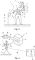
- the protective device 1 not only generates and outputs an emergency signal S, but also establishes a radio connection 62 (indicated by the dashed line) to a configured remote location 60 with a transmission unit 64, such as a mobile radio transmitter 63, and thus another, distant person 61 alarms, as in Figure 4 shown.
- a radio connection 62 indicated by the dashed line
- “removed” means that this further person 61 is at least so far away from the accident victim 8 that this additional person 61 cannot perceive the state of the accident victim either visually or acoustically.
- the additional person 61 can, for example, sit in an emergency center, which can be in a completely different place.
- the protective device 1 can establish the radio connection 62 directly via the transmission unit 64, for example by means of a mobile radio transmitter 63 which is integrated in the item of clothing 2, for example again as part of an intelligent clothing.
- the protective device 1 can also establish the radio connection 62 indirectly, for example by connecting the protective device 1 via the transmitting unit 64 via a suitable data connection 65, for example Bluetooth, to a mobile terminal 66 of the person 8, for example a smartphone (for example by means of Bluetooth). which then establishes the radio connection 62 to the remote location 60, as in Figure 5 shown.
- a predetermined message can be sent via the radio connection 62, for example a text message (for example by SMS), a data transmission (for example by e-mail) or a call.
- the other person 61 in the remote location 60 can also carry a mobile terminal 67 with them, which can be connected to the radio link 62 if necessary, for example via a mobile radio network. It is obvious that the remote location 60 (eg emergency center) does not have to be location-specific, in particular if the additional person 61 also uses a mobile terminal 67 for contacting.
- a mobile terminal 67 for contacting.
- the transmitter unit 64 e.g. in the form of a mobile radio transmitter 63, can itself be integrated in the evaluation unit 6 or in the item of clothing 2 (for example in the form of intelligent clothing).
- the transmission unit 64 can be controlled by the evaluation unit 6 of the protective device 1.
- the further person 61 can then coordinate help for the accident victim 8.
- the location of people 8 who work on live or live systems can be known.
- maintenance work on a power supply network is planned and it is known when and where it is carried out.
- the protective device 1 can be assigned to a specific person 8 and can also have a unique identification (for example a mobile phone number). In this way, an incoming emergency call from a protective device 1 can be assigned to a location and / or a person 8 in the emergency center, with the help of a helper being able to be coordinated in a targeted manner.
- the protective device 1 can also be equipped with a unit for determining the position.
- the unit 72 for position determination for example a GPS (Global Positioning System) sensor, can be arranged on the item of clothing 2 (as in FIG Figure 6 indicated by dashed lines), or integrated into this, for example in intelligent clothing with integrated electronics.
- GPS Global Positioning System
- GALILEO satellite Navigation systems
- the availability of WLAN (Wireless LAN) networks could be used to draw a conclusion about the current position.
- a position could be determined via a mobile radio network, for example by means of GSM location.
- the protective device 1 can also be connected to an external device 70, which can carry out a position determination, as a unit 72 for position determination, for example in FIG Figure 6 shown.
- the protective device 1 can thus be connected to the external device 70 via a data connection 71, for example Bluetooth, in order to obtain the current position of the person 8 from the external device 70.
- a transmission unit 64 could again be provided in the protective device 1 for the connection.
- the current position can be stored in the protective device 1, preferably in the evaluation unit 6 of the protective device 1, preferably with further details of a power accident, such as date, time, duration of the body current, level of the current flow, in order to enable a later evaluation.
- the current position is understood to mean both geocoordinates and a specific location. Since many external devices 70 often also have a location function, the location can also be used directly as the current position.
- the current position or location can also be at a remote location 60 (as in FIG Figure 4 or 5 ) are transmitted to support the coordination of help for the accident victim 8.
- the current position or the current location could also be transmitted to the remote location 60 at certain time intervals in order to always know a current position or a current location of the person 8.
- the protective device 1 can of course also transmit additional information, for example data from further sensors 9 on the protective device 1 relating to the condition of the person 8, for example the position of the person 8 (case, person is lying ), Pulse, ECG, breathing. Such additional information can be important for the coordination of aid and the rescue operation.
- the remote location 60 can of course also be automated in such a way that in the event of an incoming message from a power accident to a person 8, certain actions are taken automatically, for example the notification of an emergency medical service or helper, possibly also with the specific position or location of the person 8 and possibly also with other existing data.
- the remote location 60 could also determine one or more helpers in the vicinity of the person 8 involved in the accident and inform them specifically about the power accident.
- the helper can be equipped with a communication unit, for example a cell phone or smart phone, which is operated by the remote location 60 or by another person 61 is contacted in the remote location 60 with a corresponding message.
- the message could be an SMS, email, or something similar, or a call.
- a helper in the vicinity of the accident victim could be determined by knowing the positions of all the assistants in question in the remote location 60. For example, the current position could be continuously transmitted to the remote location 60 via the communication units of the helpers at predetermined intervals. Proximity could also be determined in such a way that it is determined whether a communication unit of the accident victim 8, for example a mobile terminal 66, can exchange messages with a communication unit of a helper, for example via Bluetooth, or whether both can receive the same WLAN network , This could also be continuously communicated to the remote location 60 by the respective communication unit so that the remote location 60 always has a current status.
- a protective device 1 according to the invention can also be used advantageously in such cases, as shown in FIG Figure 7 is described as an example.
- each protective device 1a, 1b can be designed with a communication unit 80a, 80b in order to be able to set up a communication connection 81, for example Bluetooth.
- the communication connection 81 can also be established indirectly, for example as for Figure 5 explained to a person 8a, 8b via a mobile terminal 66.
- the communication units 80a, 80b of the two protective devices 1a, 1b do not have to communicate directly with one another.
- a communication center 82 be set up in the area of the work, with which the individual protective devices 1a, 1b connect via their communication units 80a, 80b, as in FIG Figure 7 indicated.
- the communication link 81 is then established via the communication center 82.
- the communication link 81 can be permanently established, or can also be set up on a case-by-case basis. If a protective device 1a triggers an emergency signal S for a person 8a because this person 8a gets into a circuit, the at least one additional person 8b in the vicinity is communicated via the communication unit 80a of the protective device 1a via the communication connection 81 and the communication unit 80b of the protective device 1b above it informed.
- a corresponding signaling unit for example an acoustic, visual or palpable alarm, can also be provided on a protective device 1. If a protective device 1 is additionally provided with a unique identifier, it can also be transmitted which protective device 1 is affected in order to make it easier for the accident victim 8a to be found. Aid for an accident victim 8a can thus be considerably accelerated.
- the communication described could also be via a (arbitrarily) distant location 60 as a communication center, for example as in Figure 4 or 5 described.
- the protective device 1 of the person 8 involved in the accident, or a communication unit 80 of the protective device 1 and also an external device 70 coupled to it, for example a mobile telephone which the person 8 is carrying, can also surround, possibly also with a loud acoustic signal, optionally also with a spoken warning text untrained and not equipped, 8 people to the danger and the help needed.
- An acoustic warning such as "Warning - power accident - this person is live. Do not touch the person. Disconnect the circuit or knock the person off the circuit" or "Warning - power accident - this person has received an electric shock. Touchable parts under voltage are nearby" would be conceivable, for example.
- a radio connection for transmitting the output signal S from the protective device 1 to a radio receiver 90 with an emergency signal input 21 it can of course be checked, either continuously or at least at the beginning of the work, whether there is a radio connection at all. If not, a corresponding alarm can be displayed on the protective device 1, for example acoustically, visually or palpably. The same naturally applies if a low charge state of an energy supply of the protective device 1 is determined in the protective device 1.
- the radio connection between the protective device 1 and the radio receiver for receiving the output signal can break off easily and unrecognized, in particular if the person wearing the protective device 1 moves. This can lead to false triggers if a missing radio signal in the radio receiver triggers a switching action. In the worst case, the protective person 1 no longer provides protection for the person wearing 8 without being noticed.
- radio receivers 90a, 90b each with an emergency signal input 21 for receiving an emergency signal S from the protective device 1 can be provided spatially distributed in the work area of the person 8, as in FIG Figure 8 shown.
- a radio receiver 90a, 90b can be used with a switch tester 10 as described above in order to detect an emergency signal S from the protective device 1 and to trigger an action.
- the emergency signal input 21 would be external to the switch test device 10 and the switch test device 10 would be connected to the external emergency signal input 21 on the radio receiver 90a, 90b.
- the protective device 1 is in a bidirectional radio connection with the radio receivers 90a, 90b.
- a signal receiver 91 must be provided on the protective device 1 in order to be able to receive a radio signal F which is emitted by a transmitter 92a, 92b in the radio receiver 90a, 90b.
- the signal receiver 91 is preferably arranged on the item of clothing 2 or integrated in the item of clothing 2 and connected to the evaluation unit 6 or another computing unit in the protective device 1.
- the radio signal F from a radio receiver 90a, 90b is emitted continuously or at least at regular intervals, and is received by the signal receiver 91 of the protective device 1.
- the protective device 1 is thus able to evaluate the signal quality of the radio channel between the protective device 1 and a radio receiver 90a, 90b.
- the protective device 1 can thus decide via which of the available radio channels the emergency signal S is sent.
- a large number of such radio receivers 90a, 90b can be arranged in a building or a system, and the protective device 1 selects a radio receiver 90a, 90b, for example the radio channel with the best signal quality, in order to transmit the emergency signal S thereover. In this way, the person 8 wearing the protective device 1 can move through the building or the system without losing the radio connection.
- the decision is made about which radio receiver 90a, 90b is to be used for communication.
- the decision could be made in the signal receiver 91, in the radio receivers 90a, 90b or in the switch tester 10 or elsewhere.
Landscapes
- Physics & Mathematics (AREA)
- General Physics & Mathematics (AREA)
- Business, Economics & Management (AREA)
- Emergency Management (AREA)
- Health & Medical Sciences (AREA)
- Cardiology (AREA)
- Pulmonology (AREA)
- Biophysics (AREA)
- Electromagnetism (AREA)
- Heart & Thoracic Surgery (AREA)
- Physical Education & Sports Medicine (AREA)
- Physiology (AREA)
- Life Sciences & Earth Sciences (AREA)
- General Health & Medical Sciences (AREA)
- Gerontology & Geriatric Medicine (AREA)
- Engineering & Computer Science (AREA)
- Computer Networks & Wireless Communication (AREA)
- Alarm Systems (AREA)
- Testing Relating To Insulation (AREA)
Priority Applications (1)
| Application Number | Priority Date | Filing Date | Title |
|---|---|---|---|
| PL19181148T PL3588718T3 (pl) | 2018-06-21 | 2019-06-19 | Urządzenie do testowania przełączników z wyposażeniem ochronnym przed porażeniem prądem |
Applications Claiming Priority (1)
| Application Number | Priority Date | Filing Date | Title |
|---|---|---|---|
| AT505052018 | 2018-06-21 |
Publications (3)
| Publication Number | Publication Date |
|---|---|
| EP3588718A2 true EP3588718A2 (fr) | 2020-01-01 |
| EP3588718A3 EP3588718A3 (fr) | 2020-03-25 |
| EP3588718B1 EP3588718B1 (fr) | 2022-03-02 |
Family
ID=66998289
Family Applications (1)
| Application Number | Title | Priority Date | Filing Date |
|---|---|---|---|
| EP19181148.8A Active EP3588718B1 (fr) | 2018-06-21 | 2019-06-19 | Appareil de contrôle de commutateur pourvu d'équipement de protection contre les chocs électriques |
Country Status (3)
| Country | Link |
|---|---|
| EP (1) | EP3588718B1 (fr) |
| ES (1) | ES2910150T3 (fr) |
| PL (1) | PL3588718T3 (fr) |
Cited By (1)
| Publication number | Priority date | Publication date | Assignee | Title |
|---|---|---|---|---|
| CN113447160A (zh) * | 2020-03-26 | 2021-09-28 | 本德尔有限两合公司 | 通过检测和评估身体医学因素来防止电击的方法和装置 |
Citations (2)
| Publication number | Priority date | Publication date | Assignee | Title |
|---|---|---|---|---|
| DE3903025A1 (de) | 1989-02-02 | 1990-08-09 | Asea Brown Boveri | Verfahren zum schutz von personen |
| DE4438063A1 (de) | 1994-10-25 | 1995-05-24 | Rene Haimerl | Drahtlose Schutzvorrichtung zur Arbeit an spannungsführenden Teilen |
Family Cites Families (2)
| Publication number | Priority date | Publication date | Assignee | Title |
|---|---|---|---|---|
| US9494632B1 (en) * | 2013-10-01 | 2016-11-15 | Hd Electric Company | High-voltage detector monitoring system |
| EP3446468B1 (fr) * | 2016-04-19 | 2023-04-12 | Industrial Scientific Corporation | Synchronisation dans un réseau maillé sans fil |
-
2019
- 2019-06-19 PL PL19181148T patent/PL3588718T3/pl unknown
- 2019-06-19 EP EP19181148.8A patent/EP3588718B1/fr active Active
- 2019-06-19 ES ES19181148T patent/ES2910150T3/es active Active
Patent Citations (2)
| Publication number | Priority date | Publication date | Assignee | Title |
|---|---|---|---|---|
| DE3903025A1 (de) | 1989-02-02 | 1990-08-09 | Asea Brown Boveri | Verfahren zum schutz von personen |
| DE4438063A1 (de) | 1994-10-25 | 1995-05-24 | Rene Haimerl | Drahtlose Schutzvorrichtung zur Arbeit an spannungsführenden Teilen |
Cited By (1)
| Publication number | Priority date | Publication date | Assignee | Title |
|---|---|---|---|---|
| CN113447160A (zh) * | 2020-03-26 | 2021-09-28 | 本德尔有限两合公司 | 通过检测和评估身体医学因素来防止电击的方法和装置 |
Also Published As
| Publication number | Publication date |
|---|---|
| PL3588718T3 (pl) | 2022-05-02 |
| EP3588718B1 (fr) | 2022-03-02 |
| ES2910150T3 (es) | 2022-05-11 |
| EP3588718A3 (fr) | 2020-03-25 |
Similar Documents
| Publication | Publication Date | Title |
|---|---|---|
| EP3811347B1 (fr) | Agencement et procédé pour renforcer la sécurité d'une personne en cas d'accident électrique | |
| AT521697B1 (de) | Mobiler Elektroverteiler mit Notsignaleingang | |
| AT521137B1 (de) | Mobiler Elektroarbeitsplatz mit Schutzausrüstung gegen Stromschlag | |
| EP3588717B1 (fr) | Appareil de contrôle de relais pourvu d'équipement de protection contre les chocs électriques | |
| WO2023166191A1 (fr) | Détecteur de tension portable et système d'avertissement de dangers de tension | |
| AT521135B1 (de) | Elektrische Anlage mit einer Mehrzahl elektrischer Stromkreise und Schutzausrüstung gegen Stromschlag | |
| AT521371B1 (de) | Elektrische Anlage mit Notsignaleingang zum Empfangen eines über Funk gesendeten Notsignals | |
| EP3588718B1 (fr) | Appareil de contrôle de commutateur pourvu d'équipement de protection contre les chocs électriques | |
| EP3588715B1 (fr) | Appareil de contrôle de transformateur pourvu d'équipement de protection contre les chocs électriques | |
| WO2019243380A1 (fr) | Poste de vérification haute tension à équipement de protection contre les décharges électriques | |
| WO2019243383A1 (fr) | Poste de travail électrique doté d'un équipement de protection contre les décharges électriques | |
| EP3588716B1 (fr) | Appareil de contrôle de convertisseur pourvu d'équipement de protection contre les chocs électriques | |
| AT521138B1 (de) | Anordnung und Verfahren zur Koordination von Hilfe im Falle eines Stromunfalls | |
| WO2017167331A1 (fr) | Vêtement de protection | |
| DE102012201769B4 (de) | Verfahren und Gerät zum Schutz von Rettungskräften vor Stromschlägen |
Legal Events
| Date | Code | Title | Description |
|---|---|---|---|
| PUAI | Public reference made under article 153(3) epc to a published international application that has entered the european phase |
Free format text: ORIGINAL CODE: 0009012 |
|
| STAA | Information on the status of an ep patent application or granted ep patent |
Free format text: STATUS: THE APPLICATION HAS BEEN PUBLISHED |
|
| AK | Designated contracting states |
Kind code of ref document: A2 Designated state(s): AL AT BE BG CH CY CZ DE DK EE ES FI FR GB GR HR HU IE IS IT LI LT LU LV MC MK MT NL NO PL PT RO RS SE SI SK SM TR |
|
| AX | Request for extension of the european patent |
Extension state: BA ME |
|
| PUAL | Search report despatched |
Free format text: ORIGINAL CODE: 0009013 |
|
| AK | Designated contracting states |
Kind code of ref document: A3 Designated state(s): AL AT BE BG CH CY CZ DE DK EE ES FI FR GB GR HR HU IE IS IT LI LT LU LV MC MK MT NL NO PL PT RO RS SE SI SK SM TR |
|
| AX | Request for extension of the european patent |
Extension state: BA ME |
|
| RIC1 | Information provided on ipc code assigned before grant |
Ipc: G01R 19/00 20060101ALI20200215BHEP Ipc: G08B 21/00 20060101ALI20200215BHEP Ipc: H02H 5/12 20060101AFI20200215BHEP Ipc: A41D 13/00 20060101ALI20200215BHEP Ipc: H04W 48/10 20090101ALI20200215BHEP |
|
| STAA | Information on the status of an ep patent application or granted ep patent |
Free format text: STATUS: REQUEST FOR EXAMINATION WAS MADE |
|
| 17P | Request for examination filed |
Effective date: 20200903 |
|
| RAP3 | Party data changed (applicant data changed or rights of an application transferred) |
Owner name: ADAPTIVE REGELSYSTEME GESELLSCHAFT MBH |
|
| GRAP | Despatch of communication of intention to grant a patent |
Free format text: ORIGINAL CODE: EPIDOSNIGR1 |
|
| STAA | Information on the status of an ep patent application or granted ep patent |
Free format text: STATUS: GRANT OF PATENT IS INTENDED |
|
| GRAJ | Information related to disapproval of communication of intention to grant by the applicant or resumption of examination proceedings by the epo deleted |
Free format text: ORIGINAL CODE: EPIDOSDIGR1 |
|
| GRAP | Despatch of communication of intention to grant a patent |
Free format text: ORIGINAL CODE: EPIDOSNIGR1 |
|
| INTG | Intention to grant announced |
Effective date: 20211014 |
|
| INTG | Intention to grant announced |
Effective date: 20211027 |
|
| GRAS | Grant fee paid |
Free format text: ORIGINAL CODE: EPIDOSNIGR3 |
|
| GRAA | (expected) grant |
Free format text: ORIGINAL CODE: 0009210 |
|
| STAA | Information on the status of an ep patent application or granted ep patent |
Free format text: STATUS: THE PATENT HAS BEEN GRANTED |
|
| AK | Designated contracting states |
Kind code of ref document: B1 Designated state(s): AL AT BE BG CH CY CZ DE DK EE ES FI FR GB GR HR HU IE IS IT LI LT LU LV MC MK MT NL NO PL PT RO RS SE SI SK SM TR |
|
| REG | Reference to a national code |
Ref country code: GB Ref legal event code: FG4D Free format text: NOT ENGLISH |
|
| REG | Reference to a national code |
Ref country code: CH Ref legal event code: EP Ref country code: AT Ref legal event code: REF Ref document number: 1473039 Country of ref document: AT Kind code of ref document: T Effective date: 20220315 |
|
| REG | Reference to a national code |
Ref country code: DE Ref legal event code: R096 Ref document number: 502019003531 Country of ref document: DE |
|
| REG | Reference to a national code |
Ref country code: IE Ref legal event code: FG4D Free format text: LANGUAGE OF EP DOCUMENT: GERMAN |
|
| REG | Reference to a national code |
Ref country code: SE Ref legal event code: TRGR |
|
| REG | Reference to a national code |
Ref country code: ES Ref legal event code: FG2A Ref document number: 2910150 Country of ref document: ES Kind code of ref document: T3 Effective date: 20220511 |
|
| REG | Reference to a national code |
Ref country code: LT Ref legal event code: MG9D |
|
| REG | Reference to a national code |
Ref country code: NL Ref legal event code: MP Effective date: 20220302 |
|
| PG25 | Lapsed in a contracting state [announced via postgrant information from national office to epo] |
Ref country code: RS Free format text: LAPSE BECAUSE OF FAILURE TO SUBMIT A TRANSLATION OF THE DESCRIPTION OR TO PAY THE FEE WITHIN THE PRESCRIBED TIME-LIMIT Effective date: 20220302 Ref country code: NO Free format text: LAPSE BECAUSE OF FAILURE TO SUBMIT A TRANSLATION OF THE DESCRIPTION OR TO PAY THE FEE WITHIN THE PRESCRIBED TIME-LIMIT Effective date: 20220602 Ref country code: LT Free format text: LAPSE BECAUSE OF FAILURE TO SUBMIT A TRANSLATION OF THE DESCRIPTION OR TO PAY THE FEE WITHIN THE PRESCRIBED TIME-LIMIT Effective date: 20220302 Ref country code: HR Free format text: LAPSE BECAUSE OF FAILURE TO SUBMIT A TRANSLATION OF THE DESCRIPTION OR TO PAY THE FEE WITHIN THE PRESCRIBED TIME-LIMIT Effective date: 20220302 Ref country code: BG Free format text: LAPSE BECAUSE OF FAILURE TO SUBMIT A TRANSLATION OF THE DESCRIPTION OR TO PAY THE FEE WITHIN THE PRESCRIBED TIME-LIMIT Effective date: 20220602 |
|
| PG25 | Lapsed in a contracting state [announced via postgrant information from national office to epo] |
Ref country code: LV Free format text: LAPSE BECAUSE OF FAILURE TO SUBMIT A TRANSLATION OF THE DESCRIPTION OR TO PAY THE FEE WITHIN THE PRESCRIBED TIME-LIMIT Effective date: 20220302 Ref country code: GR Free format text: LAPSE BECAUSE OF FAILURE TO SUBMIT A TRANSLATION OF THE DESCRIPTION OR TO PAY THE FEE WITHIN THE PRESCRIBED TIME-LIMIT Effective date: 20220603 Ref country code: FI Free format text: LAPSE BECAUSE OF FAILURE TO SUBMIT A TRANSLATION OF THE DESCRIPTION OR TO PAY THE FEE WITHIN THE PRESCRIBED TIME-LIMIT Effective date: 20220302 |
|
| PG25 | Lapsed in a contracting state [announced via postgrant information from national office to epo] |
Ref country code: NL Free format text: LAPSE BECAUSE OF FAILURE TO SUBMIT A TRANSLATION OF THE DESCRIPTION OR TO PAY THE FEE WITHIN THE PRESCRIBED TIME-LIMIT Effective date: 20220302 |
|
| PG25 | Lapsed in a contracting state [announced via postgrant information from national office to epo] |
Ref country code: SM Free format text: LAPSE BECAUSE OF FAILURE TO SUBMIT A TRANSLATION OF THE DESCRIPTION OR TO PAY THE FEE WITHIN THE PRESCRIBED TIME-LIMIT Effective date: 20220302 Ref country code: SK Free format text: LAPSE BECAUSE OF FAILURE TO SUBMIT A TRANSLATION OF THE DESCRIPTION OR TO PAY THE FEE WITHIN THE PRESCRIBED TIME-LIMIT Effective date: 20220302 Ref country code: RO Free format text: LAPSE BECAUSE OF FAILURE TO SUBMIT A TRANSLATION OF THE DESCRIPTION OR TO PAY THE FEE WITHIN THE PRESCRIBED TIME-LIMIT Effective date: 20220302 Ref country code: PT Free format text: LAPSE BECAUSE OF FAILURE TO SUBMIT A TRANSLATION OF THE DESCRIPTION OR TO PAY THE FEE WITHIN THE PRESCRIBED TIME-LIMIT Effective date: 20220704 Ref country code: EE Free format text: LAPSE BECAUSE OF FAILURE TO SUBMIT A TRANSLATION OF THE DESCRIPTION OR TO PAY THE FEE WITHIN THE PRESCRIBED TIME-LIMIT Effective date: 20220302 Ref country code: CZ Free format text: LAPSE BECAUSE OF FAILURE TO SUBMIT A TRANSLATION OF THE DESCRIPTION OR TO PAY THE FEE WITHIN THE PRESCRIBED TIME-LIMIT Effective date: 20220302 |
|
| PG25 | Lapsed in a contracting state [announced via postgrant information from national office to epo] |
Ref country code: IS Free format text: LAPSE BECAUSE OF FAILURE TO SUBMIT A TRANSLATION OF THE DESCRIPTION OR TO PAY THE FEE WITHIN THE PRESCRIBED TIME-LIMIT Effective date: 20220702 Ref country code: AL Free format text: LAPSE BECAUSE OF FAILURE TO SUBMIT A TRANSLATION OF THE DESCRIPTION OR TO PAY THE FEE WITHIN THE PRESCRIBED TIME-LIMIT Effective date: 20220302 |
|
| REG | Reference to a national code |
Ref country code: DE Ref legal event code: R097 Ref document number: 502019003531 Country of ref document: DE |
|
| PLBE | No opposition filed within time limit |
Free format text: ORIGINAL CODE: 0009261 |
|
| STAA | Information on the status of an ep patent application or granted ep patent |
Free format text: STATUS: NO OPPOSITION FILED WITHIN TIME LIMIT |
|
| PG25 | Lapsed in a contracting state [announced via postgrant information from national office to epo] |
Ref country code: MC Free format text: LAPSE BECAUSE OF FAILURE TO SUBMIT A TRANSLATION OF THE DESCRIPTION OR TO PAY THE FEE WITHIN THE PRESCRIBED TIME-LIMIT Effective date: 20220302 Ref country code: DK Free format text: LAPSE BECAUSE OF FAILURE TO SUBMIT A TRANSLATION OF THE DESCRIPTION OR TO PAY THE FEE WITHIN THE PRESCRIBED TIME-LIMIT Effective date: 20220302 |
|
| 26N | No opposition filed |
Effective date: 20221205 |
|
| REG | Reference to a national code |
Ref country code: BE Ref legal event code: MM Effective date: 20220630 |
|
| PG25 | Lapsed in a contracting state [announced via postgrant information from national office to epo] |
Ref country code: SI Free format text: LAPSE BECAUSE OF FAILURE TO SUBMIT A TRANSLATION OF THE DESCRIPTION OR TO PAY THE FEE WITHIN THE PRESCRIBED TIME-LIMIT Effective date: 20220302 |
|
| PG25 | Lapsed in a contracting state [announced via postgrant information from national office to epo] |
Ref country code: LU Free format text: LAPSE BECAUSE OF NON-PAYMENT OF DUE FEES Effective date: 20220619 Ref country code: IE Free format text: LAPSE BECAUSE OF NON-PAYMENT OF DUE FEES Effective date: 20220619 |
|
| PG25 | Lapsed in a contracting state [announced via postgrant information from national office to epo] |
Ref country code: BE Free format text: LAPSE BECAUSE OF NON-PAYMENT OF DUE FEES Effective date: 20220630 |
|
| P01 | Opt-out of the competence of the unified patent court (upc) registered |
Effective date: 20230615 |
|
| PGFP | Annual fee paid to national office [announced via postgrant information from national office to epo] |
Ref country code: ES Payment date: 20230721 Year of fee payment: 5 |
|
| PG25 | Lapsed in a contracting state [announced via postgrant information from national office to epo] |
Ref country code: MK Free format text: LAPSE BECAUSE OF FAILURE TO SUBMIT A TRANSLATION OF THE DESCRIPTION OR TO PAY THE FEE WITHIN THE PRESCRIBED TIME-LIMIT Effective date: 20220302 Ref country code: CY Free format text: LAPSE BECAUSE OF FAILURE TO SUBMIT A TRANSLATION OF THE DESCRIPTION OR TO PAY THE FEE WITHIN THE PRESCRIBED TIME-LIMIT Effective date: 20220302 |
|
| PG25 | Lapsed in a contracting state [announced via postgrant information from national office to epo] |
Ref country code: HU Free format text: LAPSE BECAUSE OF FAILURE TO SUBMIT A TRANSLATION OF THE DESCRIPTION OR TO PAY THE FEE WITHIN THE PRESCRIBED TIME-LIMIT; INVALID AB INITIO Effective date: 20190619 |
|
| PG25 | Lapsed in a contracting state [announced via postgrant information from national office to epo] |
Ref country code: MT Free format text: LAPSE BECAUSE OF FAILURE TO SUBMIT A TRANSLATION OF THE DESCRIPTION OR TO PAY THE FEE WITHIN THE PRESCRIBED TIME-LIMIT Effective date: 20220302 |
|
| PGFP | Annual fee paid to national office [announced via postgrant information from national office to epo] |
Ref country code: PL Payment date: 20250523 Year of fee payment: 7 Ref country code: DE Payment date: 20250623 Year of fee payment: 7 |
|
| PGFP | Annual fee paid to national office [announced via postgrant information from national office to epo] |
Ref country code: GB Payment date: 20250627 Year of fee payment: 7 |
|
| PGFP | Annual fee paid to national office [announced via postgrant information from national office to epo] |
Ref country code: FR Payment date: 20250627 Year of fee payment: 7 |
|
| PGFP | Annual fee paid to national office [announced via postgrant information from national office to epo] |
Ref country code: TR Payment date: 20250613 Year of fee payment: 7 |
|
| REG | Reference to a national code |
Ref country code: ES Ref legal event code: FD2A Effective date: 20250729 |
|
| PGFP | Annual fee paid to national office [announced via postgrant information from national office to epo] |
Ref country code: SE Payment date: 20250627 Year of fee payment: 7 |
|
| REG | Reference to a national code |
Ref country code: AT Ref legal event code: MM01 Ref document number: 1473039 Country of ref document: AT Kind code of ref document: T Effective date: 20240619 |
|
| PG25 | Lapsed in a contracting state [announced via postgrant information from national office to epo] |
Ref country code: ES Free format text: LAPSE BECAUSE OF NON-PAYMENT OF DUE FEES Effective date: 20240620 |
|
| PGFP | Annual fee paid to national office [announced via postgrant information from national office to epo] |
Ref country code: IT Payment date: 20250605 Year of fee payment: 7 |
|
| PG25 | Lapsed in a contracting state [announced via postgrant information from national office to epo] |
Ref country code: AT Free format text: LAPSE BECAUSE OF NON-PAYMENT OF DUE FEES Effective date: 20240619 |
|
| PGFP | Annual fee paid to national office [announced via postgrant information from national office to epo] |
Ref country code: CH Payment date: 20250717 Year of fee payment: 7 |
|
| PGFP | Annual fee paid to national office [announced via postgrant information from national office to epo] |
Ref country code: AT Payment date: 20260410 Year of fee payment: 5 |