EP3588751A1 - Générateur d'une éolienne dotée d'un adaptateur d'écoulement d'air - Google Patents
Générateur d'une éolienne dotée d'un adaptateur d'écoulement d'air Download PDFInfo
- Publication number
- EP3588751A1 EP3588751A1 EP18180384.2A EP18180384A EP3588751A1 EP 3588751 A1 EP3588751 A1 EP 3588751A1 EP 18180384 A EP18180384 A EP 18180384A EP 3588751 A1 EP3588751 A1 EP 3588751A1
- Authority
- EP
- European Patent Office
- Prior art keywords
- air flow
- generator
- rotor
- adaptor
- air
- Prior art date
- Legal status (The legal status is an assumption and is not a legal conclusion. Google has not performed a legal analysis and makes no representation as to the accuracy of the status listed.)
- Granted
Links
Images


Classifications
-
- H—ELECTRICITY
- H02—GENERATION; CONVERSION OR DISTRIBUTION OF ELECTRIC POWER
- H02K—DYNAMO-ELECTRIC MACHINES
- H02K1/00—Details of the magnetic circuit
- H02K1/06—Details of the magnetic circuit characterised by the shape, form or construction
- H02K1/22—Rotating parts of the magnetic circuit
- H02K1/27—Rotor cores with permanent magnets
- H02K1/2786—Outer rotors
- H02K1/2787—Outer rotors the magnetisation axis of the magnets being perpendicular to the rotor axis
- H02K1/2788—Outer rotors the magnetisation axis of the magnets being perpendicular to the rotor axis the rotor consisting of a single magnet or two or more axially juxtaposed single magnets
-
- H—ELECTRICITY
- H02—GENERATION; CONVERSION OR DISTRIBUTION OF ELECTRIC POWER
- H02K—DYNAMO-ELECTRIC MACHINES
- H02K9/00—Arrangements for cooling or ventilating
- H02K9/02—Arrangements for cooling or ventilating by ambient air flowing through the machine
-
- F—MECHANICAL ENGINEERING; LIGHTING; HEATING; WEAPONS; BLASTING
- F03—MACHINES OR ENGINES FOR LIQUIDS; WIND, SPRING, OR WEIGHT MOTORS; PRODUCING MECHANICAL POWER OR A REACTIVE PROPULSIVE THRUST, NOT OTHERWISE PROVIDED FOR
- F03D—WIND MOTORS
- F03D9/00—Adaptations of wind motors for special use; Combinations of wind motors with apparatus driven thereby; Wind motors specially adapted for installation in particular locations
- F03D9/20—Wind motors characterised by the driven apparatus
- F03D9/25—Wind motors characterised by the driven apparatus the apparatus being an electrical generator
-
- H—ELECTRICITY
- H02—GENERATION; CONVERSION OR DISTRIBUTION OF ELECTRIC POWER
- H02K—DYNAMO-ELECTRIC MACHINES
- H02K1/00—Details of the magnetic circuit
- H02K1/06—Details of the magnetic circuit characterised by the shape, form or construction
- H02K1/22—Rotating parts of the magnetic circuit
- H02K1/28—Means for mounting or fastening rotating magnetic parts on to, or to, the rotor structures
- H02K1/30—Means for mounting or fastening rotating magnetic parts on to, or to, the rotor structures using intermediate parts, e.g. spiders
-
- H—ELECTRICITY
- H02—GENERATION; CONVERSION OR DISTRIBUTION OF ELECTRIC POWER
- H02K—DYNAMO-ELECTRIC MACHINES
- H02K2201/00—Specific aspects not provided for in the other groups of this subclass relating to the magnetic circuits
- H02K2201/03—Machines characterised by aspects of the air-gap between rotor and stator
-
- Y—GENERAL TAGGING OF NEW TECHNOLOGICAL DEVELOPMENTS; GENERAL TAGGING OF CROSS-SECTIONAL TECHNOLOGIES SPANNING OVER SEVERAL SECTIONS OF THE IPC; TECHNICAL SUBJECTS COVERED BY FORMER USPC CROSS-REFERENCE ART COLLECTIONS [XRACs] AND DIGESTS
- Y02—TECHNOLOGIES OR APPLICATIONS FOR MITIGATION OR ADAPTATION AGAINST CLIMATE CHANGE
- Y02E—REDUCTION OF GREENHOUSE GAS [GHG] EMISSIONS, RELATED TO ENERGY GENERATION, TRANSMISSION OR DISTRIBUTION
- Y02E10/00—Energy generation through renewable energy sources
- Y02E10/70—Wind energy
- Y02E10/72—Wind turbines with rotation axis in wind direction
Definitions
- a prior art wind turbine comprises a generator having a rotor and a stator, wherein the rotor is rotated with respect to the stator.
- the rotor is usually equipped with permanent magnets, while the stator is provided with windings.
- the generator produces an AC power.
- an air gap is provided between the rotor and the stator, in which cooling air is allowed to flow.
- EP 2 434 617 A1 discloses a generator having a stator and a rotor, which rotor being rotatable around a center axis and relatively to the stator, and the stator being built of a stator stack comprising a number of adjacently disposed metal plates.
- the stator comprises a number of stator windings at least partially wound around the metal plates with a certain distance to each other, whereby at least one radial duct-like channel is provided between two or more adjacently disposed metal plates by means of at least one spacer.
- the spacer is arranged underneath the stator windings in such a manner that the radial duct-like channel is radially open.
- the cooling air can flow into the stator both from the drive end and the non-drive end of the generator.
- An air flow has to pass through the coils winding head into the air gap (i.e. the distance between stator and rotor).
- the establishment of sufficient cooling efficiency is one of the main tasks in the design of a generator.
- a higher cooling capacity allows to increase the generator power output.
- a good cooling efficiency often requires relative large generator fans.
- a generator in particular for a wind turbine, comprising: a stator comprising coils windings; a rotor which is rotatable arranged around the stator and comprises at least one permanent magnet, wherein the coil windings of the stator generate an AC power when the rotor is rotated; an air gap between the stator and the rotor, through which an air flow is allowed to flow, the air gap having an entrance side where air enters the air gap and an outlet side where the air leaves the air gap; and an air flow adaptor provided on the rotor at the entrance side of the air gap, wherein air flow adaptor is configured to alter the air flow in the air gap.
- the pressure drop at the entrance side of the air gap could be eliminated or at least significantly reduced by means of the air flow adaptor.
- the air flow adaptor smoothens the flow path and therefore reduces the pressure loss at the entrance side of the air gap.
- the flow at the entrance side of the air gap can be optimized in a manner that the pressure drop of the flow can be reduced which contributes to the system pressure drop reduction.
- more cooling flow can be extracted by use of the same generator fans and the same cooling system.
- the cooling efficiency or capacity can be increased, which can be translated to a higher generator rated power and AEP improvement.
- the air flow adaptor can be configured to alter a velocity and/or a direction of the air flow, and/or the air flow adaptor can be configured to produce the air flow as a laminar flow.
- the air flow adaptor is releasable attached to the rotor or a tip of the at least one permanent magnet.
- the air flow adaptor can be made of a synthetic resin.
- the air flow adaptor can have a first surface which is substantially flush with a second surface of the at least one permanent magnet, wherein the first and second surfaces form the air gap.
- the generator may comprise an attachment structure which allows to attach the air flow adaptor in a form-fit manner or a force-fit manner to the rotor, wherein the attachment structure may comprise at least one of a bolt, a rivet, a clip, a fastener, a bracket, and a spring.
- the air flow adaptor can comprise at least one shell, frame, container or scoop to accommodate the at least one permanent magnet, and the air flow adaptor is attached to the rotor.
- the air flow adaptor can thus accommodate different permanent magnets of different shapes, while the outer shape of the air flow adaptor is kept the same.
- different air flow adaptors can be provided for different generators, where the outer shape of the air flow adaptor can be optimized to the dedicated generator to reduce the pressure drop.
- the air flow adaptor has an additional function to attach the permanent magnet to the rotor.
- a preferred design of the air flow adaptor can be made in that the air flow adaptor is formed such that the height of the air gap is reduced along the air flow direction.
- the air flow adaptor can comprise, at its upstream end in the air flow direction, a guiding surface for guiding the air flow, the guiding surface comprises a radius in a plane including the axial direction and the radial direction.
- each air flow adaptor can have a radius or a convex shape at its up-stream end in the air flow direction when viewed in the radial direction.
- a second aspect of the present invention is directed to a wind turbine comprising the generator of the first aspect.
- a third aspect of the present invention is directed to an air flow adaptor to be mounted to a rotor or a magnet tip of a permanent magnet of the rotor of a generator, said air flow adaptor being configured to adapt an air flow flowing through an air gap between a stator and a rotor of the generator.
- Such an air flow adaptor is preferably suitably to be retrofitted at already existing generators.
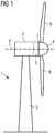
- Fig. 1 shows a wind turbine 1.
- the wind turbine 1 comprises a nacelle 3 and a tower 2.
- the nacelle 3 is mounted at the top of the tower 2.
- the nacelle 3 is mounted rotatable with regard to the tower 2 by means of a yaw bearing.
- the axis of rotation of the nacelle 3 with regard to the tower 2 is referred to as the yaw axis.
- the wind turbine 1 also comprises a hub 4 with three rotor blades 6 (of which two rotor blades 6 are depicted in Fig. 1 ).
- the hub 4 is mounted rotatable with regard to the nacelle 3 by means of a main bearing 7.
- the hub 4 is mounted rotatable about a rotor axis of rotation 8.
- the wind turbine 1 furthermore comprises a generator 5.
- the generator 5 in turn comprises a rotor 10 (see Fig. 2 ) connecting the generator 5 with the hub 4.
- the hub 4 is connected directly to the generator 5, thus the wind turbine 1 is referred to as a gearless, direct-driven wind turbine.
- Such a generator 5 is referred as direct drive generator 5.
- the hub 4 may also be connected to the generator 5 via a gear box.
- This type of wind turbine 1 is referred to as a geared wind turbine.
- the present invention is suitable for both types of wind turbines 1.
- the generator 5 is accommodated within the nacelle 3.
- the generator 5 is arranged and prepared for converting the rotational energy from the hub 4 into electrical energy in the shape of an AC power.
- One end of the generator 5 at the hub side is referred as drive end, and the other end of the generator 5 at the nacelle side is referred as non-drive end.
- Fig. 2 is a perspective view of parts of the generator 5.
- the generator 5 comprises a stator 9 and the rotor 10 inside the nacelle 3.
- the rotor 10 comprises a rotor housing 13, and permanent magnets 11 are arranged in a circumferential direction at the inner surface of rotor housing 13.
- the stator 9 comprises a stator yoke (not shown) and a number of parallel teeth 12 extending from the outer surface of the stator yoke.
- the teeth 12 are arranged with a certain distance from each other to provide a gap or slot for stator windings, which are not shown in Fig. 2 .
- the teeth 12 penetrate a finger plate 14.
- cooling pipes can be are provided beneath the slots.
- a coolant like water, oil or a coolant comprising water or oil may flow through the cooling pipe effectively removing the heat.
- the heat is dissipated by an air flow which is described in further details below.
- Fig. 3 shows a perspective view of parts of a first embodiment of the generator 5.
- the air gap has an entrance side where air enters the air gap and an outlet side where the air leaves the air gap.
- the air flow can flow from the drive-side to the non-drive side.
- the air flow can flow from the non-drive side to the drive side.
- the air flow flows from the non-drive side as well as from the drive side to be merged and discharged through cooling ducts which are arranged in a middle section between the non-drive side and the drive side of the generator 5.
- At least one air flow adaptor 15 is provided on the rotor housing 13 of the rotor 10 at the entrance side of the air gap, wherein air flow adaptor 15 is configured to alter the air flow in the air gap.
- the air flow adaptor 15 is configured to alter a velocity and/or a direction of the air flow.
- the air flow adaptor 15 is configured to make the air flow laminar.
- the air flow adaptor 15 has a first surface which is substantially flush with a second surface of the at least one permanent magnet 11, wherein the first and second surfaces form the air gap.
- the air flow adaptor 15 is releasable attached to a tip of the permanent magnet 11.
- the air flow adaptor 15 is made of a synthetic resin, wherein its outer shape is adapted to an outer shape of the permanent magnet 11.
- the air flow adaptor 15 comprises an attachment structure which allows to attach the air flow adaptor 15 in a form-fit manner to the rotor housing 13.
- the attachment structure can be formed to attach the air flow adaptor 15 to the rotor housing 13in a force-fit manner.
- the attachment structure can be formed of y synthetic resin and may include metal parts such as springs, bolts, rivets, clips, fasteners, brackets, etc.
- the rotor 10 is rotatable around the axis extending in an axial direction 8 of the generator 5.
- An air flow direction of the air flow in the air gap is directed in the axial direction 8 from the entrance side to the outlet side of the air gap.
- the air gap has a height from the stator 9 to the rotor 10 in a radial direction perpendicular to the axial direction 8.
- the air flow adaptor 15 is formed such that the height of the air gap is reduced along the air flow direction.
- the air flow adaptor 15 comprises, at its up-stream end in the air flow direction, a guiding surface 16 for guiding the air flow, the guiding surface 16 comprises a radius in a plane including the axial direction 8 and the radial direction.
- each air flow adaptor 15 has a radius or a convex shape at its upstream end in the air flow direction when viewed in the radial direction.
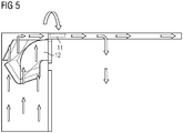
- Fig. 5 shows an air flow through the generator, where the air flow is indicated by arrows.
- the air flow vertically flows from the bottom to the top in Fig. 5 through the windings.
- the air flow is horizontally deflected to flow from the left side to the right side. Thereby, the air flow passes the air gap.
- the entrance side of the air gap is located at the non-drive side on the left side in Fig. 5 , where air enters the air gap.
- the air flows downwards through cooling ducts which are arranged in a middle section between the non-drive side and the drive side of the generator 5.
- a second entrance side of the air gap can be provided at the drive side on the right side in Fig. 5 .
- the air flowing from the non-drive side as well as from the drive side is merged and discharged through the cooling ducts which are arranged in a middle section between the non-drive side and the drive side of the generator 5.
- the present invention enables to remarkably reduce that pressure drop.
- the pressure drop at the entrance side of the air gap could be eliminated or at least significantly be reduced by means of the air flow adaptor 15.
- the air flow adaptor 15 smoothens the flow path and therefore reduces the pressure loss at the entrance side of the air gap.
- the flow at the entrance side of the air gap can be optimized in a manner that the pressure drop of the flow can be reduced which contributes to the system pressure drop reduction.
- more cooling flow can be extracted by use of the same generator fans and the same cooling system.
- the cooling capacity can be increased which can be translated to a higher generator rated power and AEP improvement.
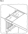
- Fig. 4 shows a perspective view of parts of the generator according to a second embodiment.
- the generator of the second embodiment has substantially the same features of the generator of the first embodiment. In the following, the differences between the first and second embodiments are described.
- the air flow adaptor 15' includes two scoops 18. Each scoop 18 of the air flow adaptor 15' is configured to accommodate a permanent magnet 11.
- the air flow adaptor 15' is attached to the rotor housing 13 of the rotor 10. There is a distance between the two scoops 18 corresponding to the arrangement gap 18 between the adjacent permanent magnets 11 of the first embodiment.
- the air flow adaptor 15' can accommodate different permanent magnets 11 of different shapes, while the outer shape of the air flow adaptor 15' is maintained.
- different air flow adaptors 15' can be provided for different generators, where the outer shape of each air flow adaptor 15' can be optimized to the dedicated generator to reduce the pressure drop.
- the air flow adaptor 15' has an additional function to attach the two permanent magnets 11 to the rotor housing 13.
Landscapes
- Engineering & Computer Science (AREA)
- Power Engineering (AREA)
- Motor Or Generator Cooling System (AREA)
- Connection Of Motors, Electrical Generators, Mechanical Devices, And The Like (AREA)
Priority Applications (1)
| Application Number | Priority Date | Filing Date | Title |
|---|---|---|---|
| EP18180384.2A EP3588751B1 (fr) | 2018-06-28 | 2018-06-28 | Générateur d'une éolienne dotée d'un adaptateur d'écoulement d'air |
Applications Claiming Priority (1)
| Application Number | Priority Date | Filing Date | Title |
|---|---|---|---|
| EP18180384.2A EP3588751B1 (fr) | 2018-06-28 | 2018-06-28 | Générateur d'une éolienne dotée d'un adaptateur d'écoulement d'air |
Publications (2)
| Publication Number | Publication Date |
|---|---|
| EP3588751A1 true EP3588751A1 (fr) | 2020-01-01 |
| EP3588751B1 EP3588751B1 (fr) | 2021-01-27 |
Family
ID=62816358
Family Applications (1)
| Application Number | Title | Priority Date | Filing Date |
|---|---|---|---|
| EP18180384.2A Active EP3588751B1 (fr) | 2018-06-28 | 2018-06-28 | Générateur d'une éolienne dotée d'un adaptateur d'écoulement d'air |
Country Status (1)
| Country | Link |
|---|---|
| EP (1) | EP3588751B1 (fr) |
Citations (6)
| Publication number | Priority date | Publication date | Assignee | Title |
|---|---|---|---|---|
| JP2001339925A (ja) * | 2000-05-30 | 2001-12-07 | Honda Motor Co Ltd | アウターロータ型モータ・ジェネレータ |
| EP2395631A1 (fr) * | 2009-02-09 | 2011-12-14 | JTEKT Corporation | Moteur électrique et rotor |
| EP2434617A1 (fr) | 2010-09-24 | 2012-03-28 | Siemens Aktiengesellschaft | Générateur pour machine électrique |
| US20120091723A1 (en) * | 2010-10-13 | 2012-04-19 | Jean Le Besnerais | Generator, in particular for a wind turbine |
| US20130257195A1 (en) * | 2012-04-03 | 2013-10-03 | Giovanni Airoldi | Rotor arrangement |
| EP3091640A1 (fr) * | 2015-05-05 | 2016-11-09 | Robert Bosch Gmbh | Rotor pour machine a flux axial |
Family Cites Families (1)
| Publication number | Priority date | Publication date | Assignee | Title |
|---|---|---|---|---|
| US9793767B2 (en) * | 2015-03-19 | 2017-10-17 | Hamilton Sundstrand Corporation | Method and assembly for cooling an electric machine |
-
2018
- 2018-06-28 EP EP18180384.2A patent/EP3588751B1/fr active Active
Patent Citations (6)
| Publication number | Priority date | Publication date | Assignee | Title |
|---|---|---|---|---|
| JP2001339925A (ja) * | 2000-05-30 | 2001-12-07 | Honda Motor Co Ltd | アウターロータ型モータ・ジェネレータ |
| EP2395631A1 (fr) * | 2009-02-09 | 2011-12-14 | JTEKT Corporation | Moteur électrique et rotor |
| EP2434617A1 (fr) | 2010-09-24 | 2012-03-28 | Siemens Aktiengesellschaft | Générateur pour machine électrique |
| US20120091723A1 (en) * | 2010-10-13 | 2012-04-19 | Jean Le Besnerais | Generator, in particular for a wind turbine |
| US20130257195A1 (en) * | 2012-04-03 | 2013-10-03 | Giovanni Airoldi | Rotor arrangement |
| EP3091640A1 (fr) * | 2015-05-05 | 2016-11-09 | Robert Bosch Gmbh | Rotor pour machine a flux axial |
Also Published As
| Publication number | Publication date |
|---|---|
| EP3588751B1 (fr) | 2021-01-27 |
Similar Documents
| Publication | Publication Date | Title |
|---|---|---|
| EP2912757B1 (fr) | Génératrice de turbine éolienne équipée d'un frein à courant de foucault, turbine éolienne ayant une telle génératrice, et procédés associés | |
| US8179002B2 (en) | Axial cooled generator | |
| EP2136077A2 (fr) | Eolienne avec système de refroidissement du générateur | |
| US20010035651A1 (en) | Wind power generating device | |
| US8362635B2 (en) | Wind-driven electric power generation system adapted for mounting along the side of vertical, man-made structures such as large buildings | |
| EP2802774B1 (fr) | Système de refroidissement d'une éolienne | |
| EP3151384B1 (fr) | Générateur de préférence d'une éolienne | |
| EP1318299A1 (fr) | Groupe générateur bulbe à turbine | |
| EP2670026A1 (fr) | Cadre de raquette | |
| EP4102683A1 (fr) | Refroidissement d'un générateur électrique | |
| CN117477854B (zh) | 一种适用于风电半直驱机组的发电机 | |
| CN212033942U (zh) | 电机及风力发电机组 | |
| US20180205272A1 (en) | Stator ring, generator and wind turbine equipped therewith | |
| EP3588751B1 (fr) | Générateur d'une éolienne dotée d'un adaptateur d'écoulement d'air | |
| KR102892890B1 (ko) | 전력 생산용 발전기 및 풍력 터빈 | |
| CA2752979A1 (fr) | Generateur pour une machine electrique | |
| CN103987962B (zh) | 用于将风力转化为电力的风力涡轮轴向磁通发电机 | |
| SE0802459A1 (sv) | Effektökande stolpliknande anordning för luftturbin | |
| EP3869670A1 (fr) | Générateur pour une machine électrique ayant un système de refroidissement amélioré et éolienne | |
| US8742635B2 (en) | Turbo generator with exciter having pressure recovery | |
| US20230023771A1 (en) | Cooling of active elements of electrical machines | |
| CN221633493U (zh) | 一种适于轴向通风冷却的风力发电机定子机座结构 | |
| EP4116583A1 (fr) | Générateur de turbine éolienne comportant un circuit de refroidissement | |
| TW202610177A (zh) | 同步機之定子與同步機 | |
| EP3955421A1 (fr) | Stator segmenté pour générateur, comprenant une sangle de fixation d'une bobine d'extrémité |
Legal Events
| Date | Code | Title | Description |
|---|---|---|---|
| PUAI | Public reference made under article 153(3) epc to a published international application that has entered the european phase |
Free format text: ORIGINAL CODE: 0009012 |
|
| STAA | Information on the status of an ep patent application or granted ep patent |
Free format text: STATUS: THE APPLICATION HAS BEEN PUBLISHED |
|
| AK | Designated contracting states |
Kind code of ref document: A1 Designated state(s): AL AT BE BG CH CY CZ DE DK EE ES FI FR GB GR HR HU IE IS IT LI LT LU LV MC MK MT NL NO PL PT RO RS SE SI SK SM TR |
|
| AX | Request for extension of the european patent |
Extension state: BA ME |
|
| STAA | Information on the status of an ep patent application or granted ep patent |
Free format text: STATUS: REQUEST FOR EXAMINATION WAS MADE |
|
| 17P | Request for examination filed |
Effective date: 20200205 |
|
| RBV | Designated contracting states (corrected) |
Designated state(s): AL AT BE BG CH CY CZ DE DK EE ES FI FR GB GR HR HU IE IS IT LI LT LU LV MC MK MT NL NO PL PT RO RS SE SI SK SM TR |
|
| STAA | Information on the status of an ep patent application or granted ep patent |
Free format text: STATUS: EXAMINATION IS IN PROGRESS |
|
| 17Q | First examination report despatched |
Effective date: 20200416 |
|
| GRAP | Despatch of communication of intention to grant a patent |
Free format text: ORIGINAL CODE: EPIDOSNIGR1 |
|
| STAA | Information on the status of an ep patent application or granted ep patent |
Free format text: STATUS: GRANT OF PATENT IS INTENDED |
|
| RIC1 | Information provided on ipc code assigned before grant |
Ipc: H02K 9/02 20060101AFI20200901BHEP Ipc: H02K 1/27 20060101ALN20200901BHEP Ipc: H02K 1/30 20060101ALN20200901BHEP |
|
| INTG | Intention to grant announced |
Effective date: 20201001 |
|
| GRAS | Grant fee paid |
Free format text: ORIGINAL CODE: EPIDOSNIGR3 |
|
| GRAA | (expected) grant |
Free format text: ORIGINAL CODE: 0009210 |
|
| STAA | Information on the status of an ep patent application or granted ep patent |
Free format text: STATUS: THE PATENT HAS BEEN GRANTED |
|
| AK | Designated contracting states |
Kind code of ref document: B1 Designated state(s): AL AT BE BG CH CY CZ DE DK EE ES FI FR GB GR HR HU IE IS IT LI LT LU LV MC MK MT NL NO PL PT RO RS SE SI SK SM TR |
|
| REG | Reference to a national code |
Ref country code: GB Ref legal event code: FG4D |
|
| REG | Reference to a national code |
Ref country code: CH Ref legal event code: EP |
|
| REG | Reference to a national code |
Ref country code: AT Ref legal event code: REF Ref document number: 1359221 Country of ref document: AT Kind code of ref document: T Effective date: 20210215 |
|
| REG | Reference to a national code |
Ref country code: IE Ref legal event code: FG4D |
|
| REG | Reference to a national code |
Ref country code: DE Ref legal event code: R096 Ref document number: 602018012194 Country of ref document: DE |
|
| REG | Reference to a national code |
Ref country code: NL Ref legal event code: MP Effective date: 20210127 |
|
| REG | Reference to a national code |
Ref country code: LT Ref legal event code: MG9D |
|
| REG | Reference to a national code |
Ref country code: AT Ref legal event code: MK05 Ref document number: 1359221 Country of ref document: AT Kind code of ref document: T Effective date: 20210127 |
|
| PG25 | Lapsed in a contracting state [announced via postgrant information from national office to epo] |
Ref country code: PT Free format text: LAPSE BECAUSE OF FAILURE TO SUBMIT A TRANSLATION OF THE DESCRIPTION OR TO PAY THE FEE WITHIN THE PRESCRIBED TIME-LIMIT Effective date: 20210527 Ref country code: NO Free format text: LAPSE BECAUSE OF FAILURE TO SUBMIT A TRANSLATION OF THE DESCRIPTION OR TO PAY THE FEE WITHIN THE PRESCRIBED TIME-LIMIT Effective date: 20210427 Ref country code: LT Free format text: LAPSE BECAUSE OF FAILURE TO SUBMIT A TRANSLATION OF THE DESCRIPTION OR TO PAY THE FEE WITHIN THE PRESCRIBED TIME-LIMIT Effective date: 20210127 Ref country code: GR Free format text: LAPSE BECAUSE OF FAILURE TO SUBMIT A TRANSLATION OF THE DESCRIPTION OR TO PAY THE FEE WITHIN THE PRESCRIBED TIME-LIMIT Effective date: 20210428 Ref country code: HR Free format text: LAPSE BECAUSE OF FAILURE TO SUBMIT A TRANSLATION OF THE DESCRIPTION OR TO PAY THE FEE WITHIN THE PRESCRIBED TIME-LIMIT Effective date: 20210127 Ref country code: FI Free format text: LAPSE BECAUSE OF FAILURE TO SUBMIT A TRANSLATION OF THE DESCRIPTION OR TO PAY THE FEE WITHIN THE PRESCRIBED TIME-LIMIT Effective date: 20210127 Ref country code: BG Free format text: LAPSE BECAUSE OF FAILURE TO SUBMIT A TRANSLATION OF THE DESCRIPTION OR TO PAY THE FEE WITHIN THE PRESCRIBED TIME-LIMIT Effective date: 20210427 |
|
| PG25 | Lapsed in a contracting state [announced via postgrant information from national office to epo] |
Ref country code: AT Free format text: LAPSE BECAUSE OF FAILURE TO SUBMIT A TRANSLATION OF THE DESCRIPTION OR TO PAY THE FEE WITHIN THE PRESCRIBED TIME-LIMIT Effective date: 20210127 Ref country code: LV Free format text: LAPSE BECAUSE OF FAILURE TO SUBMIT A TRANSLATION OF THE DESCRIPTION OR TO PAY THE FEE WITHIN THE PRESCRIBED TIME-LIMIT Effective date: 20210127 Ref country code: RS Free format text: LAPSE BECAUSE OF FAILURE TO SUBMIT A TRANSLATION OF THE DESCRIPTION OR TO PAY THE FEE WITHIN THE PRESCRIBED TIME-LIMIT Effective date: 20210127 Ref country code: PL Free format text: LAPSE BECAUSE OF FAILURE TO SUBMIT A TRANSLATION OF THE DESCRIPTION OR TO PAY THE FEE WITHIN THE PRESCRIBED TIME-LIMIT Effective date: 20210127 Ref country code: SE Free format text: LAPSE BECAUSE OF FAILURE TO SUBMIT A TRANSLATION OF THE DESCRIPTION OR TO PAY THE FEE WITHIN THE PRESCRIBED TIME-LIMIT Effective date: 20210127 |
|
| PG25 | Lapsed in a contracting state [announced via postgrant information from national office to epo] |
Ref country code: IS Free format text: LAPSE BECAUSE OF FAILURE TO SUBMIT A TRANSLATION OF THE DESCRIPTION OR TO PAY THE FEE WITHIN THE PRESCRIBED TIME-LIMIT Effective date: 20210527 |
|
| REG | Reference to a national code |
Ref country code: DE Ref legal event code: R097 Ref document number: 602018012194 Country of ref document: DE |
|
| PG25 | Lapsed in a contracting state [announced via postgrant information from national office to epo] |
Ref country code: SM Free format text: LAPSE BECAUSE OF FAILURE TO SUBMIT A TRANSLATION OF THE DESCRIPTION OR TO PAY THE FEE WITHIN THE PRESCRIBED TIME-LIMIT Effective date: 20210127 Ref country code: CZ Free format text: LAPSE BECAUSE OF FAILURE TO SUBMIT A TRANSLATION OF THE DESCRIPTION OR TO PAY THE FEE WITHIN THE PRESCRIBED TIME-LIMIT Effective date: 20210127 Ref country code: EE Free format text: LAPSE BECAUSE OF FAILURE TO SUBMIT A TRANSLATION OF THE DESCRIPTION OR TO PAY THE FEE WITHIN THE PRESCRIBED TIME-LIMIT Effective date: 20210127 |
|
| PG25 | Lapsed in a contracting state [announced via postgrant information from national office to epo] |
Ref country code: RO Free format text: LAPSE BECAUSE OF FAILURE TO SUBMIT A TRANSLATION OF THE DESCRIPTION OR TO PAY THE FEE WITHIN THE PRESCRIBED TIME-LIMIT Effective date: 20210127 Ref country code: DK Free format text: LAPSE BECAUSE OF FAILURE TO SUBMIT A TRANSLATION OF THE DESCRIPTION OR TO PAY THE FEE WITHIN THE PRESCRIBED TIME-LIMIT Effective date: 20210127 Ref country code: SK Free format text: LAPSE BECAUSE OF FAILURE TO SUBMIT A TRANSLATION OF THE DESCRIPTION OR TO PAY THE FEE WITHIN THE PRESCRIBED TIME-LIMIT Effective date: 20210127 |
|
| PLBE | No opposition filed within time limit |
Free format text: ORIGINAL CODE: 0009261 |
|
| STAA | Information on the status of an ep patent application or granted ep patent |
Free format text: STATUS: NO OPPOSITION FILED WITHIN TIME LIMIT |
|
| 26N | No opposition filed |
Effective date: 20211028 |
|
| PG25 | Lapsed in a contracting state [announced via postgrant information from national office to epo] |
Ref country code: AL Free format text: LAPSE BECAUSE OF FAILURE TO SUBMIT A TRANSLATION OF THE DESCRIPTION OR TO PAY THE FEE WITHIN THE PRESCRIBED TIME-LIMIT Effective date: 20210127 Ref country code: MC Free format text: LAPSE BECAUSE OF FAILURE TO SUBMIT A TRANSLATION OF THE DESCRIPTION OR TO PAY THE FEE WITHIN THE PRESCRIBED TIME-LIMIT Effective date: 20210127 Ref country code: ES Free format text: LAPSE BECAUSE OF FAILURE TO SUBMIT A TRANSLATION OF THE DESCRIPTION OR TO PAY THE FEE WITHIN THE PRESCRIBED TIME-LIMIT Effective date: 20210127 |
|
| REG | Reference to a national code |
Ref country code: CH Ref legal event code: PL |
|
| PG25 | Lapsed in a contracting state [announced via postgrant information from national office to epo] |
Ref country code: SI Free format text: LAPSE BECAUSE OF FAILURE TO SUBMIT A TRANSLATION OF THE DESCRIPTION OR TO PAY THE FEE WITHIN THE PRESCRIBED TIME-LIMIT Effective date: 20210127 |
|
| REG | Reference to a national code |
Ref country code: BE Ref legal event code: MM Effective date: 20210630 |
|
| PG25 | Lapsed in a contracting state [announced via postgrant information from national office to epo] |
Ref country code: LU Free format text: LAPSE BECAUSE OF NON-PAYMENT OF DUE FEES Effective date: 20210628 |
|
| PG25 | Lapsed in a contracting state [announced via postgrant information from national office to epo] |
Ref country code: LI Free format text: LAPSE BECAUSE OF NON-PAYMENT OF DUE FEES Effective date: 20210630 Ref country code: IT Free format text: LAPSE BECAUSE OF FAILURE TO SUBMIT A TRANSLATION OF THE DESCRIPTION OR TO PAY THE FEE WITHIN THE PRESCRIBED TIME-LIMIT Effective date: 20210127 Ref country code: IE Free format text: LAPSE BECAUSE OF NON-PAYMENT OF DUE FEES Effective date: 20210628 Ref country code: CH Free format text: LAPSE BECAUSE OF NON-PAYMENT OF DUE FEES Effective date: 20210630 |
|
| PG25 | Lapsed in a contracting state [announced via postgrant information from national office to epo] |
Ref country code: IS Free format text: LAPSE BECAUSE OF FAILURE TO SUBMIT A TRANSLATION OF THE DESCRIPTION OR TO PAY THE FEE WITHIN THE PRESCRIBED TIME-LIMIT Effective date: 20210527 |
|
| PG25 | Lapsed in a contracting state [announced via postgrant information from national office to epo] |
Ref country code: BE Free format text: LAPSE BECAUSE OF NON-PAYMENT OF DUE FEES Effective date: 20210630 |
|
| REG | Reference to a national code |
Ref country code: DE Ref legal event code: R082 Ref document number: 602018012194 Country of ref document: DE Representative=s name: SAUTHOFF, KARSTEN, DIPL.-ING. UNIV., DE |
|
| PG25 | Lapsed in a contracting state [announced via postgrant information from national office to epo] |
Ref country code: NL Free format text: LAPSE BECAUSE OF NON-PAYMENT OF DUE FEES Effective date: 20210127 Ref country code: CY Free format text: LAPSE BECAUSE OF FAILURE TO SUBMIT A TRANSLATION OF THE DESCRIPTION OR TO PAY THE FEE WITHIN THE PRESCRIBED TIME-LIMIT Effective date: 20210127 |
|
| PG25 | Lapsed in a contracting state [announced via postgrant information from national office to epo] |
Ref country code: HU Free format text: LAPSE BECAUSE OF FAILURE TO SUBMIT A TRANSLATION OF THE DESCRIPTION OR TO PAY THE FEE WITHIN THE PRESCRIBED TIME-LIMIT; INVALID AB INITIO Effective date: 20180628 |
|
| PG25 | Lapsed in a contracting state [announced via postgrant information from national office to epo] |
Ref country code: MK Free format text: LAPSE BECAUSE OF FAILURE TO SUBMIT A TRANSLATION OF THE DESCRIPTION OR TO PAY THE FEE WITHIN THE PRESCRIBED TIME-LIMIT Effective date: 20210127 |
|
| PG25 | Lapsed in a contracting state [announced via postgrant information from national office to epo] |
Ref country code: MT Free format text: LAPSE BECAUSE OF FAILURE TO SUBMIT A TRANSLATION OF THE DESCRIPTION OR TO PAY THE FEE WITHIN THE PRESCRIBED TIME-LIMIT Effective date: 20210127 |
|
| PGFP | Annual fee paid to national office [announced via postgrant information from national office to epo] |
Ref country code: DE Payment date: 20250626 Year of fee payment: 8 |
|
| PGFP | Annual fee paid to national office [announced via postgrant information from national office to epo] |
Ref country code: GB Payment date: 20250617 Year of fee payment: 8 |
|
| PGFP | Annual fee paid to national office [announced via postgrant information from national office to epo] |
Ref country code: FR Payment date: 20250624 Year of fee payment: 8 |
|
| PG25 | Lapsed in a contracting state [announced via postgrant information from national office to epo] |
Ref country code: TR Free format text: LAPSE BECAUSE OF FAILURE TO SUBMIT A TRANSLATION OF THE DESCRIPTION OR TO PAY THE FEE WITHIN THE PRESCRIBED TIME-LIMIT Effective date: 20210127 |