EP3588824B1 - Procédé par lequel un terminal exécute une superposition d'informations de commande v2x dans un système de communication sans fil, et terminal associé - Google Patents
Procédé par lequel un terminal exécute une superposition d'informations de commande v2x dans un système de communication sans fil, et terminal associé Download PDFInfo
- Publication number
- EP3588824B1 EP3588824B1 EP17900910.5A EP17900910A EP3588824B1 EP 3588824 B1 EP3588824 B1 EP 3588824B1 EP 17900910 A EP17900910 A EP 17900910A EP 3588824 B1 EP3588824 B1 EP 3588824B1
- Authority
- EP
- European Patent Office
- Prior art keywords
- symbol
- control information
- control
- scheduling
- mapped
- Prior art date
- Legal status (The legal status is an assumption and is not a legal conclusion. Google has not performed a legal analysis and makes no representation as to the accuracy of the status listed.)
- Active
Links
Images


































Classifications
-
- H—ELECTRICITY
- H04—ELECTRIC COMMUNICATION TECHNIQUE
- H04L—TRANSMISSION OF DIGITAL INFORMATION, e.g. TELEGRAPHIC COMMUNICATION
- H04L1/00—Arrangements for detecting or preventing errors in the information received
- H04L1/12—Arrangements for detecting or preventing errors in the information received by using return channel
- H04L1/16—Arrangements for detecting or preventing errors in the information received by using return channel in which the return channel carries supervisory signals, e.g. repetition request signals
- H04L1/1607—Details of the supervisory signal
- H04L1/1664—Details of the supervisory signal the supervisory signal being transmitted together with payload signals; piggybacking
-
- H—ELECTRICITY
- H04—ELECTRIC COMMUNICATION TECHNIQUE
- H04W—WIRELESS COMMUNICATION NETWORKS
- H04W72/00—Local resource management
- H04W72/20—Control channels or signalling for resource management
-
- H—ELECTRICITY
- H04—ELECTRIC COMMUNICATION TECHNIQUE
- H04L—TRANSMISSION OF DIGITAL INFORMATION, e.g. TELEGRAPHIC COMMUNICATION
- H04L1/00—Arrangements for detecting or preventing errors in the information received
-
- H—ELECTRICITY
- H04—ELECTRIC COMMUNICATION TECHNIQUE
- H04L—TRANSMISSION OF DIGITAL INFORMATION, e.g. TELEGRAPHIC COMMUNICATION
- H04L1/00—Arrangements for detecting or preventing errors in the information received
- H04L1/0001—Systems modifying transmission characteristics according to link quality, e.g. power backoff
- H04L1/0002—Systems modifying transmission characteristics according to link quality, e.g. power backoff by adapting the transmission rate
- H04L1/0003—Systems modifying transmission characteristics according to link quality, e.g. power backoff by adapting the transmission rate by switching between different modulation schemes
-
- H—ELECTRICITY
- H04—ELECTRIC COMMUNICATION TECHNIQUE
- H04L—TRANSMISSION OF DIGITAL INFORMATION, e.g. TELEGRAPHIC COMMUNICATION
- H04L1/00—Arrangements for detecting or preventing errors in the information received
- H04L1/0001—Systems modifying transmission characteristics according to link quality, e.g. power backoff
- H04L1/0009—Systems modifying transmission characteristics according to link quality, e.g. power backoff by adapting the channel coding
- H04L1/001—Systems modifying transmission characteristics according to link quality, e.g. power backoff by adapting the channel coding applied to control information
-
- H—ELECTRICITY
- H04—ELECTRIC COMMUNICATION TECHNIQUE
- H04L—TRANSMISSION OF DIGITAL INFORMATION, e.g. TELEGRAPHIC COMMUNICATION
- H04L1/00—Arrangements for detecting or preventing errors in the information received
- H04L1/004—Arrangements for detecting or preventing errors in the information received by using forward error control
- H04L1/0056—Systems characterized by the type of code used
- H04L1/0067—Rate matching
-
- H—ELECTRICITY
- H04—ELECTRIC COMMUNICATION TECHNIQUE
- H04L—TRANSMISSION OF DIGITAL INFORMATION, e.g. TELEGRAPHIC COMMUNICATION
- H04L1/00—Arrangements for detecting or preventing errors in the information received
- H04L1/12—Arrangements for detecting or preventing errors in the information received by using return channel
- H04L1/16—Arrangements for detecting or preventing errors in the information received by using return channel in which the return channel carries supervisory signals, e.g. repetition request signals
-
- H—ELECTRICITY
- H04—ELECTRIC COMMUNICATION TECHNIQUE
- H04L—TRANSMISSION OF DIGITAL INFORMATION, e.g. TELEGRAPHIC COMMUNICATION
- H04L5/00—Arrangements affording multiple use of the transmission path
- H04L5/003—Arrangements for allocating sub-channels of the transmission path
- H04L5/0048—Allocation of pilot signals, i.e. of signals known to the receiver
-
- H—ELECTRICITY
- H04—ELECTRIC COMMUNICATION TECHNIQUE
- H04L—TRANSMISSION OF DIGITAL INFORMATION, e.g. TELEGRAPHIC COMMUNICATION
- H04L5/00—Arrangements affording multiple use of the transmission path
- H04L5/003—Arrangements for allocating sub-channels of the transmission path
- H04L5/0048—Allocation of pilot signals, i.e. of signals known to the receiver
- H04L5/005—Allocation of pilot signals, i.e. of signals known to the receiver of common pilots, i.e. pilots destined for multiple users or terminals
-
- H—ELECTRICITY
- H04—ELECTRIC COMMUNICATION TECHNIQUE
- H04L—TRANSMISSION OF DIGITAL INFORMATION, e.g. TELEGRAPHIC COMMUNICATION
- H04L5/00—Arrangements affording multiple use of the transmission path
- H04L5/003—Arrangements for allocating sub-channels of the transmission path
- H04L5/0053—Allocation of signalling, i.e. of overhead other than pilot signals
-
- H—ELECTRICITY
- H04—ELECTRIC COMMUNICATION TECHNIQUE
- H04W—WIRELESS COMMUNICATION NETWORKS
- H04W4/00—Services specially adapted for wireless communication networks; Facilities therefor
- H04W4/30—Services specially adapted for particular environments, situations or purposes
- H04W4/40—Services specially adapted for particular environments, situations or purposes for vehicles, e.g. vehicle-to-pedestrians [V2P]
-
- H—ELECTRICITY
- H04—ELECTRIC COMMUNICATION TECHNIQUE
- H04L—TRANSMISSION OF DIGITAL INFORMATION, e.g. TELEGRAPHIC COMMUNICATION
- H04L5/00—Arrangements affording multiple use of the transmission path
- H04L5/003—Arrangements for allocating sub-channels of the transmission path
- H04L5/0048—Allocation of pilot signals, i.e. of signals known to the receiver
- H04L5/0051—Allocation of pilot signals, i.e. of signals known to the receiver of dedicated pilots, i.e. pilots destined for a single user or terminal
-
- H—ELECTRICITY
- H04—ELECTRIC COMMUNICATION TECHNIQUE
- H04W—WIRELESS COMMUNICATION NETWORKS
- H04W72/00—Local resource management
- H04W72/04—Wireless resource allocation
- H04W72/044—Wireless resource allocation based on the type of the allocated resource
- H04W72/0453—Resources in frequency domain, e.g. a carrier in FDMA
Definitions
- the present document relates to wireless communication and, more specifically, to a V2X control information piggyback method performed by a terminal in a wireless communication system, and a terminal using the same.
- IMT-Advanced aims to support IP (Internet Protocol) based multimedia service at data rates of 1Gbps in a stationary and low-speed moving state and 100Mbps in a high-speed moving state.
- IP Internet Protocol
- LTE-A LTE-Advanced
- OFDMA Orthogonal Frequency Division Multiple Access
- LTE-A Single Carrier- LTE-Advanced
- D2D Device-to-Device
- D2D is attracting attention as a communication technology for the public safety network.
- Commercial communication networks are rapidly changing to LTE, but current public safety networks are mainly based on 2G technology in terms of conflicts with existing communication standards and cost.
- Public safety networks have higher service requirements (reliability and security) than commercial communication networks and require direct signal transmission and reception, or D2D operation, between devices, especially when the coverage of cellular communications is insufficient or unavailable.
- D2D operation in general can have a variety of advantages in that it transmits and receives signals between nearby devices.
- the D2D UE has high data rate and low delay and is capable of data communication.
- the D2D operation can disperse the traffic to the base station, and can also expand the coverage of the base station if the UE performing the D2D operation acts as a repeater.
- the D2D communication may expand and be applicable for signal transmission and reception between vehicles, and vehicle-related communication is referred to as Vehicle-To-Everything (V2X) communication.
- V2X Vehicle-To-Everything
- V2X means pedestrian (communication between a vehicle and a device carried by an individual (e.g.,) handheld terminal carried by a pedestrian, cyclist, driver or passenger)) (V2P), vehicle (communication between vehicles) (V2V), infrastructure/network (communication between a vehicle and a roadside unit (RSU)/network (e.g.,) RSU is a transportation infrastructure entity (e.g.,) an entity transmitting speed notifications) implemented in an eNB or a stationary UE)) (V2I/N)
- V2X UE(s) piggyback and transmit control (/scheduling) information e.g., "MCS INDEX(/MODULATION ORDER)" and/or “TBS INDEX (/TRANSPORT BLOCK SIZE)" (along with "data") on a channel (e.g., a PSSCH) designated in advance are proposed in the following.
- WO2016/209056 relates to a method in which a terminal transmits a device-to-device (D2D) signal in a wireless communication system.
- the D2D signal transmission method includes: transmitting D2D control information; and transmitting D2D data corresponding to the D2D control information, wherein the D2D control information and the D2D data are transmitted in the same subframe, and the D2D control information and the D2D data are always adjacent to each other in the frequency axis.
- the operation method may comprise generating control information which includes parameters used for transmitting and receiving data; transmitting, to a second UE, the control information through a physical sidelink control channel (PSCCH); and transmitting, to the second UE, the data through a physical sidelink shared channel (PSSCH) based on the parameters.
- PSCCH physical sidelink control channel
- PSSCH physical sidelink shared channel
- An object of the present document is to provide a V2X transmission resource selection method performed by a UE in a wireless communication system and a UE using the same.
- the coded symbols related to the control information may be mapped to regions adjacent to reference signal symbols.
- the coded symbols related to the control information may be not mapped on symbols before the first reference signal symbol and symbols after the last reference signal symbol on the subframe.
- a spacing between the coded symbols related to the control information which are consecutively mapped on the same frequency of the subframe may be maximized.
- the subframe may include a plurality of reference signal symbols.
- the reference signal symbols may be demodulation reference signal (DMRS) symbols.
- DMRS demodulation reference signal
- the control information may be a modulation and coding scheme (MCS) index.
- MCS modulation and coding scheme
- Resources in which the control information is transmitted may be fixed.
- a user equipment (UE) according to claim 9 is provided.
- a UE can transmit control information with stability by mapping coded symbols related to the control information to a region adjacent to a reference signal and transmitting the control information through the coded symbols.
- the present document may improve "phase offset” correction and channel estimation performance by increasing a reference signal density. Accordingly, "V2X message(s) with variable sizes" can be transmitted with high reliability according to the present document.
- FIG. 1 shows a wireless communication system to which the present document is applied.
- the wireless communication system may also be referred to as an evolved-UMTS terrestrial radio access network (E-UTRAN) or a long term evolution (LTE)/LTE-A system.
- E-UTRAN evolved-UMTS terrestrial radio access network
- LTE long term evolution
- LTE-A long term evolution
- the E-UTRAN includes at least one base station (BS) 20 which provides a control plane and a user plane to a user equipment (UE) 10.
- the UE 10 may be fixed or mobile, and may be referred to as another terminology, such as a mobile station (MS), a user terminal (UT), a subscriber station (SS), a mobile terminal (MT), a wireless device, etc.
- the BS 20 is generally a fixed station that communicates with the UE 10 and may be referred to as another terminology, such as an evolved node-B (eNB), a base transceiver system (BTS), an access point, etc.
- eNB evolved node-B
- BTS base transceiver system
- access point etc.
- the BSs 20 are interconnected by means of an X2 interface.
- the BSs 20 are also connected by means of an S1 interface to an evolved packet core (EPC) 30, more specifically, to a mobility management entity (MME) through S1-MME and to a serving gateway (S-GW) through S1-U.
- EPC evolved packet core
- MME mobility management entity
- S-GW serving gateway
- the EPC 30 includes an MME, an S-GW, and a packet data network-gateway (P-GW).
- the MME has access information of the UE or capability information of the UE, and such information is generally used for mobility management of the UE.
- the S-GW is a gateway having an E-UTRAN as an end point.
- the P-GW is a gateway having a PDN as an end point.
- Layers of a radio interface protocol between the UE and the network can be classified into a first layer (L1), a second layer (L2), and a third layer (L3) based on the lower three layers of the open system interconnection (OSI) model that is well-known in the communication system.
- a physical (PHY) layer belonging to the first layer provides an information transfer service by using a physical channel
- a radio resource control (RRC) layer belonging to the third layer serves to control a radio resource between the UE and the network.
- the RRC layer exchanges an RRC message between the UE and the BS.
- FIG. 2 shows a radio frame structure of 3GPP LTE.
- a radio frame a radio frame includes 10 subframes and one subframe includes 2 slots.
- a sub frame may have a length of 1 ms and a slot may have a length of 0.5 ms.
- a time taken to transmit one subframe is referred to as a transmission time interval (TTI).
- TTI may be a minimum scheduling unit.
- One slot may include a plurality of orthogonal frequency division multiplexing (OFDM) symbols in the time domain.
- An OFDM symbol is use to represent one symbol period because 3GPP LTE uses OFDMA on downlink and may be called by other names.
- the OFDM symbol may be called an SC-FDMA symbol.
- one slot includes 7 OFDM symbols in the disclosure for example, the number of OFDM symbols included in one slot may vary according to a cyclic prefix (CP) length.
- CP cyclic prefix
- 1 subframe includes 7 OFDM symbols in CP and includes 6 OFDM symbols in extended CP.
- the structure of the radio frame is exemplary and the number of subframes included in a radio frame and the number of slots included in a subframe may be varied in various manners.
- FIG. 3 illustrates an uplink subframe structure
- an uplink subframe can be divided into a control region to which a physical uplink control channel (PUCCH) carrying uplink control information is allocated and a data region to which a physical uplink shared channel (PUSCH) carrying user data is allocated.
- PUCCH physical uplink control channel
- PUSCH physical uplink shared channel
- a PUCCH for one UE is allocated to a resource block (RB) pair in a subframe and RBs belonging to an RB pair occupy different subframes in 2 slots. This is referred to as frequency hopping of an RB pair allocated to a PUCCH on a slot boundary.
- RB resource block
- a PUCCH can support multiple formats. That is, the PUCCH can carry uplink control information having different numbers of bits per subframe according to modulation schemes. For example, 1-bit uplink control information can be transmitted over the PUCCH when Binary Phase Shift Keying (BPSK) is used (PUCCH format 1a) and 2-bit uplink control information can be transmitted over the PUCCH when Quadrature Phase Shift Keying (QPSK) is used (PUCCH format 1b).
- PUCCH formats further include format 1, format 2, format 2a and format 2b.
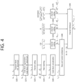
- FIG. 4 illustrates a process in which uplink control information and uplink data are multiplexed on a PUSCH.
- data bits a 0 , a 1 , ..., a A-1 are given in the form of a transport block per TTI.
- CRC cyclic redundancy check
- parity bits p 0 , p 1 , ..., p L-1 are added to the data bits a 0 , a 1 , ..., a A-1 to generate CRC added bits b 0 , b 1 , ..., b B-1 (S200).
- B A+L.
- the relationship between a k and b k can be represented as follows.
- the CRC added bits b 0 , b 1 , ..., b B-1 are segmented into code blocks and CRC parity bits are added again in units of code block (S210).
- a bit sequence output after code block segmentation is referred to as c r0 , c r1 , ..., c r(Kr-1) .
- r refers to a code block number
- Kr refers to the number of bits for the code block number r.
- Channel coding is performed on a bit sequence for a given code block (S220).
- Encoded bits are represented as d (i) 0 , d (i) 1 , ..., d (i) D-1 , D is the number of encoded bits per output stream and i is an index of an encoder output bit stream.
- Rate matching is performed on encoded bits (S230) and code block concatenation is performed thereon (S240) to generate a data bit sequence f 0 , f 1 ,..., f G-1 .
- G represents a total number of encoded bits used for transmission other than bits used for control information transmission when control information is multiplexed on a PUSCH.
- control information can be multiplexed along with data (uplink data).
- Data and control information can use different coding rates by allocating different numbers of coded symbols for transmission thereof.
- Control information includes a channel quality indicator (CQI)), a rank indicator (RI), acknowledgement/not-acknowledgement (ACK/NACK), etc.
- Channel coding is performed on CQI o 0 , o 1 , ..., o O-1 (O is the number of bits of a CQI) to generate a control information bit sequence q 0 , q 1 , ..., q QCQI-1 (S250).
- Chanel coding is performed on RI o 0 RI or RI o 0 RI , o 1 RI to generate a control information bit sequence q 0 RI , q 1 RI , ..., q QRI Rl - 1 (S260).
- channel coding is performed on ACK/NACK o 0 ACK or ACK/NACK o 0 ACK , o 1 ACK or o 0 ACK , o 1 ACK ,..., o oACK-1 ACK to generates a control information bit sequence q 0 ACK , q 1 ACK , ..., q QACK-1 ACK (S270).
- the generated data bit sequence f 0 , f 1 ,..., f G-1 and control information bit sequence q 0 , q 1 , ..., q QCQI-1 of the CQI are multiplexed into a multiplexed sequence g 0 , g 1 , ..., g H-1 (S280).
- the control information bit sequence q 0 , q 1 , ..., q QCQI-1 of the CQI may be arranged and then the data bit sequence f 0 , f 1 ,..., f G-1 may be arranged.
- the multiplexed sequence g 0 , g 1 , ..., g H-1 is mapped to a modulation sequence h 0 , h 1 , ..., h H'-1 through a channel interleaver (S280). Further, a control information bit sequence of an RI or ACK/NACK is mapped to a modulation sequence h 0 ,h 1 , ..., h H'-1 through a channel interleaver.
- h i is a modulation symbol on a constellation
- H' H+Q RI .
- Each modulation symbol of the modulation sequence h 0 ,h 1 , ..., h H'-1 is mapped to a resource element for a PUSCH.
- the resource element is an allocation unit on a subframe which is defined as 1 SC-FDMA symbol (or OFDMA symbol) and 1 subcarrier.
- FIG. 5 illustrates a reference structure for a ProSe.
- the reference structure for a ProSe includes a plurality of terminals having E-UTRAN, EPC, and ProSe application program, a ProSe application (APP) server, and a ProSe function.
- the EPC is a representative example of the E-UTRAN.
- the EPC may include an MME, an S-GW, a P-GW, a policy and charging rules function (PCRF), and a home subscriber server (HSS).
- PCRF policy and charging rules function
- HSS home subscriber server
- the ProSe application server is a user of ProSe in order to make an application function.
- the ProSe application server may communicate with an application program in the terminal.
- the application program in the terminal may use a ProSe ability to make an application function.
- the ProSe function may include at least one of following functions but is not limited thereto.
- the ProSe direct communication is a communication mode where two public safety terminals may perform direct communication through a PC 5 interface.
- the communication mode may be supported in both of a case of receiving a service in coverage of E-UTRAN or a case of separating the coverage of E-UTRAN.
- FIG. 6 illustrates arrangement examples of terminals performing ProSe direct communication and cell coverage.
- UEs A and B may be located outside of the cell coverage.
- the UE A may be located in the cell coverage and the UE B may be located outside of the cell coverage.
- both of UEs A and B may be located in the cell coverage.
- the UE A may be located in coverage of a first cell and the UE B may be in coverage of a second cell.
- the ProSe direct communication may be performed between terminals which are provided at various positions.
- Source layer-2 ID identifies a sender of a packet in a PC 5 interface.
- Purpose layer-2 ID The purpose layer-2 ID identifies a target of a packet in a PC 5 interface.
- the SA L1 ID represents an in an ID in a scheduling assignment (SA) in the PC 5 interface.
- FIG. 7 illustrates a user plane protocol stack for the ProSe direct communication.
- the PC 5 interface includes a PDCH layer, a RLC layer, a MAC layer, and a PHY layer.
- An MAC header may include the source layer-2 ID and the purpose layer-2 ID.
- a ProSe enable terminal may use following two modes with respect to resource assignments for the ProSe direct communication.
- the mode 2 is a mode for receiving scheduling a resource for the ProSe direct communication from a base station.
- the terminal should be in a RRC_CONNECTED state according to the mode 1 in order to transmit data.
- the terminal requests a transmission resource to the base station, and the base station schedules a resource for scheduling assignment and data transmission.
- the terminal may transmit a scheduling request to the base station and may transmit a Buffer Status Report (ProSe BSR).
- the base station has data which the terminal will perform the ProSe direct communication and determines whether a resource for transmitting the data is required.
- the mode 2 is a mode for selecting a direct resource.
- the terminal directly selects a resource for the ProSe direct communication from a resource pool.
- the resource pool may be configured by a network or may be previously determined.
- the terminal when the terminal includes a serving cell, that is, when the terminal is in an RRC_CONNECTED state with the base station or is located in a specific cell in an RRC_IDLE state, the terminal is regarded to be in coverage of the base station.
- the mode 1 or the mode 2 may be used according to setting of the base station.
- the terminal may change a mode from the mode 1 to the mode 2 or from the mode 2 to the mode 1.
- the ProSe direct discovery represents a process used to discover when the ProSe enabled terminal discovers other neighboring ProSe enabled terminal and refers to D2D direction discovery or D2D discovery.
- an E-UTRA wireless signal through the PC 4 interface may be used.
- information used for the ProSe direct discovery refers to discovery information.
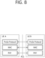
- FIG. 8 illustrates a PC 5 interface for D2D discovery.
- the PC 5 interface includes an MAC layer, a PHY layer, and a ProSe Protocol layer being an upper layer. Permission for announcement and monitoring of discovery information is handled in the upper layer ProSe Protocol. Contents of discovery information are transparent to an access stratum (AS). The ProSe Protocol allows only valid discovery information to be transferred to the AS for announcement.
- AS access stratum
- An MAC layer receives discovery information from the upper layer ProSe Protocol.
- An IP layer is not used for transmitting the discovery information.
- the MAC layer determines a resource used in order to announce the discovery information received from the upper layer.
- the MAC layer makes and sends a protocol data unit (MAC PDU) to a physical layer.
- MAC PDU protocol data unit
- the type 1 is a method assigned so that resources for announcing the discovery information are not terminal-specific and the base station provides resource pool configuration for announcing the discovery information to the terminals.
- the configuration may be included in a system information block (SIB) to be signaled in a broadcast scheme.
- SIB system information block
- the configuration may be included in a terminal specific RRC message to be provided.
- the configuration may be broadcast-signaled or terminal-specific signaled of a different layer from the RRC message.
- the terminal selects a resource from an indicated resource pool to announce discovery information using the selected resource.
- the terminal may announce discovery information through a resource optionally selected during each discovery period.
- the type 2 is a method where resources for announcing the discovery information are terminal-specifically assigned.
- a terminal in a RRC_CONNECTED state may request a resource for announcing a discovery signal to the base station through a RRC signal.
- the base station may assign a resource for announcing a discovery signal as an RRC signal.
- a resource for monitoring the discovery signal in a configured resource pool may be assigned in terminals.
- a base station may report a type 1 resource pool for announcing the discovery signal as an SIB.
- Terminals where ProSe direct discovery is allowed use a type 1 resource pool for announcing the discovery information in the RRC_IDLE state.
- the base station 2 reports that the base station supports the ProSe direct discovery through the SIB but may not provide the resource for announcing the discovery information. In this case, the terminal should enter the RRC_CONNECTED state for announcing the discovery information.
- the base station may configure whether to use a type 1 resource pool or a type 2 resource pool for announcing the discovery information through a RRC signal.
- D2D operation has various advantages because the D2D operation is signal transmission and reception between neighboring devices.
- a D2D UE can perform data communication with a high transfer rate and low delay.
- D2D operation can distribute traffic concentrating on a base station, and if a UE performing D2D operation serves as a relay, the UE can extend coverage of a base station.
- Communication including signal transmission and reception between vehicles owing to extension of the aforementioned D2D communication and related to vehicles is called V2X (vehicle-to-X) communication.
- V2X vehicle-to-X
- V2P pedestrian (communication between a vehicle and a device carried by an individual (e.g., a handheld terminal carried by a pedestrian, a cyclist, a driver or a passenger))
- V2P vehicle
- V2V vehicle
- an infrastructure/network communication between a vehicle and a roadside unit (RSU)/network
- RSU roadside unit
- V2I/N vehicle-to-X
- a (V2P communication related) device carried by a pedestrian (or individual) is called a "P-UE” and a (V2X communication related) device implemented in a vehicle is called a "V-UE”, for example.
- the term "entity” may be interpreted as a P-UE, a V-UE and/or an RSU (/network/infrastructure), for example, in the present document.
- a UE providing (or supporting) the aforementioned D2D operation may be called a D2D UE and a UE providing (or supporting) the aforementioned V2X operation may be called a V2X UE.
- a D2D UE A UE providing (or supporting) the aforementioned D2D operation
- a V2X UE a UE providing (or supporting) the aforementioned V2X operation
- embodiments of the present document will be described from the viewpoint of a V2X UE for convenience of description, description of the V2X UE can be applied to the D2D UE.
- V2X UE(s) when V2X UE(s) transmit "V2X message(s) with variable sizes" through "periodic resources (having fixed sizes)" reserved(/selected) in advance, for example, the V2X UE(s) can be defined to follow (some of) rules described below.
- V2X message(s) with variable sizes can be transmitted with high reliability.
- a V2X message can include control information and/or data.
- V2X UE(s) can be caused to consider/determine "link quality” and/or “V2X message sizes (to be transmitted)" of each transmission timing and then piggyback and transmit "modulation and coding scheme (MCS) index(/modulation order)” information along with "data" on a previously designated channel (according to the invention, a physical sidelink channel (PSSCH)).
- MCS modulation and coding scheme
- PSSCH physical sidelink channel
- channel coding different from that for "data” is applied to control information (e.g., "MCS index(/modulation order)" and/or “TBS index(/transport block size)”) piggybacked and transmitted along with the "data” on a previously designated channel a PSSCH).
- reception V2X UE(s) need to ascertain resources through which the control information is transmitted, for example, it is desirable that the positions(/sizes) of the resources be fixed.
- V2X UE(s) Only "resource position(/size)” information and "MCS index (/modulation order)” information are designated in periodic resource allocation and V2X UE(s) can be caused to consider/determine "link quality” and/or "V2X message sizes (to be transmitted)" of each transmission timing and then piggyback and transmit "TBS index(/transport block size)" information along with "data" on a previously designated channel ( a PSSCH).
- information most suitable for an actual V2X message size (to be transmitted) e.g., a minimum or closest value among values equal to or greater than the V2X message size
- the "TBS index(/transport block size)" information for example.
- V2X UE(s) piggyback and transmit control(/scheduling) information e.g., "MCS index(/modulation order)" and/or "TBS index(/transport block size)
- MCS index(/modulation order) e.g., "MCS index(/modulation order)
- TBS index(/transport block size) e.g., "TBS index(/transport block size”
- channel estimation performance based on a pre-defined(/signaled) reference signal (RS) (e.g., "DM-RS”) may decrease (/deteriorate) due to "phase drift (caused by "frequency offset” and “Doppler effect”)” and "inter-carrier interference (ICI)"
- RS pre-defined(/signaled) reference signal
- ICI inter-carrier interference
- FIGS. 9 to 13 illustrate examples of cases in which the density(/number) of reference signals used for channel estimation is increased. More specifically, FIGS. 9 to 13 illustrates cases in which the density(/number) of reference signals (e.g., "DM-RSs") used for channel estimation is increased (e.g., 4 symbols are used for reference signal (DM-RS) transmission).
- DM-RSs density(/number) of reference signals
- 4 symbols are used for reference signal (DM-RS) transmission.
- FIG. 9 illustrates a case in which 4 symbol DM-RSs are present at "symbols #2, #5, #8 and #11".
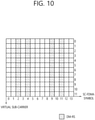
- FIG. 10 illustrates a case in which 4 symbol DM-RSs are present at "symbols #2, #4, #9 and #11".
- FIG. 11 illustrates comb-type RSs at "symbols #2, #5, #8 and #11".
- FIG. 12 illustrates FDM of RS and data at every symbol (OFDM-like structure).
- FIG. 13 illustrates FDM of RS and data at "symbols #1, #2, #3, #4, #5, #6, #7, #8, #9, #10, #11 and #12" (OFDM-like structure).
- FIG. 14 is a flowchart of a method of mapping a coded symbol related to control information on a subframe according to an embodiment of the present document.
- a UE maps coded symbols related to control information on subframes (S1410).
- the UE may be a V2X UE.
- mapping coded symbols related to control information will be described below.
- Control(/scheduling) information related "coded symbol(s)” are mapped according to (some of) the following rules (/principle).
- the (control(/scheduling) information related) "coded symbol(s)” are configured to be mapped prior to "data” (in a form in which "data” is “rate-matched") or to be mapped by "puncturing” preferentially(/first) mapped "data”, for example.
- a maximum number of control(/scheduling) information related 'coded symbol(s)′′′ may be limited to "the number of symbols to which the control(/scheduling) information related 'coded symbol(s)' are mapped” ⁇ "scheduled bandwidth (the number of subcarriers) of a channel (e.g., "PSSCH") over which the control(/scheduling) information is transmitted along with 'data′′′, for example.
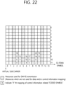
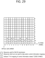
- FIGS. 15 to 23 illustrate mapping of control(/scheduling) information related "coded symbol(s)" according to (rule #1-1), (rule #1-2) and (rule #1-3) in the cases of FIG. 9 and/or FIG. 11 .
- FIGS. 15 to 23 illustrate examples of mapping control(/scheduling) information related "coded symbol(s)" according to (rule #1-1), (rule #1-2) and (rule #1-3) in the cases of FIG. 9 and/or FIG. 11 .
- the number of control(/scheduling) information related "coded symbol(s)" (to be piggybacked) is "21", for example.
- symbol positions (/resource sizes(/sizes) to which (control(/scheduling) information related) "coded symbol(s)" are mapped may be interpreted as “symbols #3/4/6/7/9/10", for example.
- control(/scheduling) information related "coded symbol(s)" mapped to "symbol #6" and “symbol #7” may be changed such that they are mapped to "symbol #7" and "symbol #6" in FIGS. 15 , 16 and 17 .
- "coded symbols #5/11/7" mapped to "symbol #6” and “coded symbols #2/8/14/20” mapped to "symbol #7” may be changed such that the former is mapped to "symbol #7” and the latter is mapped to "symbol #6" in the case of FIG. 15 .
- FIG. 24 illustrates an example of mapping control(/scheduling) information related "coded symbol(s)" according to (rule #1-1) and (rule #1-2) in the cases of FIG. 9 and/or FIG. 11 .
- the number of control(/scheduling) information related "coded symbol(s)" (to be piggybacked) is "21", for example.
- symbol positions (/resource sizes(/sizes) to which (control(/scheduling) information related) "coded symbol(s)" are mapped may be interpreted as "symbols #3/4/6/7/9/10", for example.
- control(/scheduling) information related "coded symbol(s)" are allocated while “symbol(/time) index” is increased from a minimum value (e.g., "symbol #3") of "symbol(/time) indexes” and a maximum value of "subcarrier(/frequency) indexes", and when the "symbol(/time) index" reaches a maximum value (e.g., "symbol #10"), "subcarrier(/frequency) index” is reduced one and then "symbol(/time) index” is increased again from the minimum value of "symbol(/time) indexes" (in consideration of only symbol(s)(/resource positions(/sizes)) to which the "coded symbol(s)" are mapped), for example.
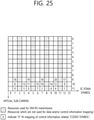
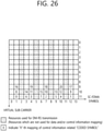
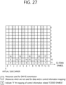
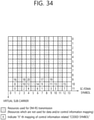
- FIGS. 25 to 34 illustrate mapping of control(/scheduling) information related "coded symbol(s)" according to (rule #1-1) and (rule #1-3) in the cases of FIG. 9 and/or FIG. 11 .
- FIGS. 25 to 34 illustrate examples of mapping control(/scheduling) information related "coded symbol(s)" according to (rule #1-1) and (rule #1-3) in the cases of FIG. 9 and/or FIG. 11 .
- the number of control(/scheduling) information related "coded symbol(s)" (to be piggybacked) is "21", for example.
- symbol positions (/resource sizes(/sizes) to which (control(/scheduling) information related) "coded symbol(s)" are mapped may be interpreted as "symbols #1/3/4/6/7/9/10/12", for example.
- control(/scheduling) information related "coded symbol(s)" mapped to "symbol #9" and “symbol #10” may be changed such that they are mapped to "symbol #10" and "symbol #9” in FIGS. 25 , 26 and 27 .
- "coded symbols #6/14" mapped to "symbol #9” and “coded symbols #4/12/20” mapped to "symbol #10” may be changed such that the former is mapped to "symbol #10" and the latter is mapped to "symbol #9” in the case of FIG. 25 .
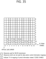
- FIG. 35 illustrates mapping of control(/scheduling) information related "coded symbol(s)" according to (rule #1-1) in the cases of FIG. 9 and/or FIG. 11 .
- FIG. 35 illustrates an example of mapping control(/scheduling) information related "coded symbol(s)" according to (rule #1-1) in the cases of FIG. 9 and/or FIG. 11 .
- the number of control(/scheduling) information related "coded symbol(s)" (to be piggybacked) is "21", for example.
- symbol positions (/resource sizes(/sizes) to which (control(/scheduling) information related) "coded symbol(s)" are mapped may be interpreted as "symbols #1/3/4/6/7/9/10/12", for example.
- control(/scheduling) information related "coded symbol(s)" are allocated while “symbol(/time) index” is increased from a minimum value (e.g., "symbol #1”) of "symbol(/time) indexes” and a maximum value of "subcarrier(/frequency) indexes", and when the "symbol(/time) index" reaches a maximum value (e.g., "symbol #12"), "subcarrier(/frequency) index” is reduced one and then "symbol(/time) index” is increased again from the minimum value of "symbol(/time) indexes" (in consideration of only symbol(s)(/resource positions(/sizes)) to which the "coded symbol(s)" are mapped), for example.
- a minimum value e.g., "symbol #1”
- subcarrier(/frequency) index e.g., "symbol #12”
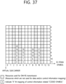
- FIGS. 36 to 39 illustrate mapping of control(/scheduling) information related "coded symbol(s)" according to (rule #1-1), (rule #1-2) and (rule #1-3) in the case of FIG. 10 .
- FIGS. 36 to 39 illustrate examples of mapping control(/scheduling) information related "coded symbol(s)" according to (rule #1-1), (rule #1-2) and (rule #1-3) in the case of FIG. 10 .
- the number of control(/scheduling) information related "coded symbol(s)" (to be piggybacked) is "21", for example.
- symbol positions (/resource sizes(/sizes) to which (control(/scheduling) information related) "coded symbol(s)" are mapped may be interpreted as "symbols #3/5/8/10", for example.
- FIG. 40 illustrates mapping of control(/scheduling) information related "coded symbol(s)" according to (rule #1-1) and (rule #1-2) in the case of FIG. 10 .
- FIG. 40 illustrates an example of mapping control(/scheduling) information related "coded symbol(s)" according to (rule #1-1) and (rule #1-2) in the case of FIG. 10 .
- the number of control(/scheduling) information related "coded symbol(s)" (to be piggybacked) is "21", for example.
- symbol positions (/resource sizes(/sizes) to which (control(/scheduling) information related) "coded symbol(s)" are mapped may be interpreted as "symbols #3/5/8/10", for example.
- control(/scheduling) information related "coded symbol(s)" are allocated while “symbol(/time) index” is increased from a minimum value (e.g., "symbol #3") of "symbol(/time) indexes” and a maximum value of "subcarrier(/frequency) indexes", and when the "symbol(/time) index" reaches a maximum value (e.g., "symbol #10"), "subcarrier(/frequency) index” is reduced one and then "symbol(/time) index” is increased again from the minimum value of "symbol(/time) indexes" (in consideration of only symbol(s)(/resource positions(/sizes)) to which the "coded symbol(s)" are mapped), for example.
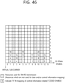
- FIGS. 41 to 49 illustrate mapping of control(/scheduling) information related "coded symbol(s)" according to (rule #1-1) and (rule #1-3) in the case of FIG. 10 .
- FIGS. 41 to 49 illustrate examples of mapping control(/scheduling) information related "coded symbol(s)" according to (rule #1-1) and (rule #1-3) in the case of FIG. 10 .
- the number of control(/scheduling) information related "coded symbol(s)" (to be piggybacked) is "21", for example.
- symbol positions (/resource sizes(/sizes) to which (control(/scheduling) information related) "coded symbol(s)" are mapped may be interpreted as "symbols #1/3/5/8/10/12", for example.
- control(/scheduling) information related "coded symbol(s)" mapped to "symbol #5" and “symbol #8” may be changed such that they are mapped to "symbol #8" and "symbol #5" in FIGS. 41 and 42 .
- "coded symbols #3/9/15" mapped to "symbol #5" and “coded symbols #2/8/14/20” mapped to "symbol #8" may be changed such that the former is mapped to "symbol #8" and the latter is mapped to "symbol #5" in the case of FIG. 41 .
- FIG. 50 illustrates mapping of control(/scheduling) information related "coded symbol(s)" according to (rule #1-1) in the case of FIG. 10 .
- FIG. 50 illustrates an example of mapping control(/scheduling) information related "coded symbol(s)" according to (rule #1-1) in the case of FIG. 10 .
- the number of control(/scheduling) information related "coded symbol(s)" (to be piggybacked) is "21", for example.
- symbol positions (/resource sizes(/sizes) to which (control(/scheduling) information related) "coded symbol(s)" are mapped may be interpreted as "symbols #1/3/5/8/10/12", for example.
- control(/scheduling) information related "coded symbol(s)" are allocated while “symbol(/time) index” is increased from a minimum value (e.g., "symbol #1”) of "symbol(/time) indexes” and a maximum value of "subcarrier(/frequency) indexes", and when the "symbol(/time) index" reaches a maximum value (e.g., "symbol #12"), "subcarrier(/frequency) index” is reduced one and then "symbol(/time) index” is increased again from the minimum value of "symbol(/time) indexes" (in consideration of only symbol(s)(/resource positions(/sizes)) to which the "coded symbol(s)" are mapped), for example.
- a minimum value e.g., "symbol #1”
- subcarrier(/frequency) index e.g., "symbol #12”
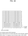
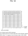
- FIGS. 51 to 54 illustrate examples of control(/scheduling) information related "coded symbol(s)".
- FIG. 51 and/or FIG. 52 and FIG. 53 and/or FIG. 54 correspond to the cases of FIG. 9 and/or FIG. 11 and FIG. 10 .
- the number of control(/scheduling) information related "coded symbol(s)" is "21", for example.
- symbol positions (/resource sizes(/sizes) to which (control(/scheduling) information related) "coded symbol(s)" are mapped may be interpreted as “symbols #0/1/3/4/6/7/9/10/12/13", “symbols #1/3/4/6/7/9/10/12", “symbols #0/1/3/5/6/7/8/10/12/13” and “symbols #1/3/5/6/7/8/10/12", for example.
- control(/scheduling) information related "coded symbol(s)" are allocated while “symbol(/time) index” is increased from a minimum value (e.g., "symbol #1" ( FIG.
- FIG. 52 and/or FIG. 54 can guarantee more advanced “control(/scheduling) information transmission/reception performance" than FIG. 51 and/or FIG. 53 (because the number of control(/scheduling) information related "coded symbol(s)" lost due to puncturing is relatively small).
- control(/scheduling) information related) "coded symbol(s)” may be configured to be mapped prior to "data” (in a form in which "data” is “rate-matched”) or to be mapped by "puncturing” preferentially(/first) mapped "data”, for example.
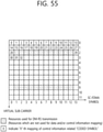
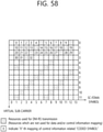
- FIGS. 55 to 58 illustrate examples of mapping control(/scheduling) information related "coded symbol(s)".
- FIG. 55 and/or FIG. 56 and FIG. 57 and/or FIG. 58 correspond to the cases of FIG. 12 and 14 .
- the number of control(/scheduling) information related "coded symbol(s)" is "33", for example.
- mapping order/puncturing(/rate matching) among symbol positions(/numbers) punctured due to a control(/scheduling) information related "coded symbol(s)" mapping rule (/direction), "AGC problem mitigation” and/or “prevention of overlap with (following WAN UL TX (SF)", (control(/scheduling) information related) "coded symbol(s)” and “data” are assumed to be the same as those in the cases of FIG. 51 to 54 , for example.
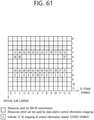
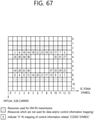
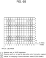
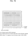
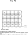
- FIGS. 59 to 73 illustrate mapping of control(/scheduling) information related "coded symbol(s)" according to (rule #1-1) and (rule #1-3)(/(rule #1-2)) in the case of FIG. 12 .
- FIGS. 59 to 73 illustrate examples of mapping control(/scheduling) information related "coded symbol(s)" according to (rule #1-1) and (rule #1-3)(/(rule #1-2)) in the case of FIG. 12 .
- the number of control(/scheduling) information related "coded symbol(s)" (to be piggybacked) is "39", for example.
- FIGS. 74 to 82 illustrate mapping of control(/scheduling) information related "coded symbol(s)" according to (rule #1-1) and (rule #1-3)(/(rule #1-2)) in the case of FIG. 13 .
- FIGS. 74 to 82 illustrate examples of mapping control(/scheduling) information related "coded symbol(s)" according to (rule #1-1) and (rule #1-3)(/(rule #1-2)) in the case of FIG. 13 .
- the number of control(/scheduling) information related "coded symbol(s)" (to be piggybacked) is "39", for example.
- rules may be defined such that (pre-defined(/signaled) control(/scheduling) information with relatively high priority (e.g., "MCS index(/modulation order)" and/or "TBS index(/transport block size)”) is transmitted as illustrated in FIGS. 15 to 50 and FIGS. 59 to 82 and control(/scheduling) information with relatively low priority (or other pieces of control(/scheduling) information) is transmitted as illustrated in FIGS. 51 to 58 .
- pre-defined(/signaled) control(/scheduling) information with relatively high priority e.g., "MCS index(/modulation order)" and/or "TBS index(/transport block size)
- rules may be defined such that control(/scheduling) information with relatively low priority is mapped to symbols on which "extra(/outer)-polation" based channel estimation is performed and control(/scheduling) information with relatively high priority is mapped to symbols on which "interpolation" based channel estimation is performed.
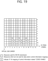
- FIG. 83 illustrates an example in which control(/scheduling) information with relatively low priority is mapped to symbols on which "extra(/outer)-polation" based channel estimation is performed and control(/scheduling) information with relatively high priority is mapped to symbols on which "interpolation" based channel estimation is performed.
- FIG. 83 illustrates an example in which a rule of mapping control(/scheduling) information with relatively low priority to symbols on which "extra(/outer)-polation" based channel estimation is performed and mapping control(/scheduling) information with relatively high priority to symbols on which "interpolation” based channel estimation is performed is applied to the state of FIG. 28 .
- the number of "coded symbol(s)" related to control(/scheduling) information with relatively high priority is "22" and the number of "coded symbol(s)” related to control(/scheduling) information with relatively low priority is "8", for example.
- a (pre-defined(/signaled) "modulation order" different from that for "data” (or the same “modulation order” as that determined for “data”) may be applied to "control/(scheduling) information (to be piggybacked)" transmitted over a specific channel (e.g., a "PSSCH") in the above-described proposed methods.
- a specific channel e.g., a "PSSCH
- piggyback control(/scheduling) information may be signaled from a base station (e.g., through SIB/(dedicated) RRC signal) or pre-defined.
- a base station e.g., through SIB/(dedicated) RRC signal
- which one of the above-described proposed methods will be used to piggyback specific control(/scheduling) information or symbol positions on which specific control(/scheduling) information will be piggybacked may be signaled from a base station or pre-defined.
- different "piggyback method” or different "piggyback symbol positions" may be applied to different pieces of control(/scheduling) information.
- the UE transmits the control information using the coded symbols (S1420).
- the control information is piggybacked along with data and transmitted.
- a detailed example in which the UE piggybacks the control information along with data has been described above.
- Examples of the above-described proposed methods can be included as one of methods implemented by the present document and can be regarded as proposed methods. Further, while the above-described proposed methods can be independently implemented, some of the proposed methods may be combined (or aggregated). For example, although the proposed methods have been described based on 3GPP LTE for convenience of description in the present document, the range of the system to which the proposed methods are applied can be extended to systems other than 3GPP LTE. For example, the proposed methods of the present document can be extended and applied to D2D communication.
- D2D communication refers to direct communication of a UE with another UE using a radio channel, for example.
- a UE refers to a user terminal
- network equipment such as a base station transmits/receives signals according to communication between UEs
- the network equipment may be regarded as a kind of UE.
- rules may be defined such that the above-described proposed methods are applied only to mode-2 (V2X(/D2D)) communication, type-1 (V2X(/D2D)) discovery (and/or mode-11 (V2X(/D2D)) communication and/or type-2 (V2X(/D2D)) discovery).
- rules may be defined such that the above-described proposed methods are applied only to in-coverage D2D(/V2X) UEs (and/or out-coverage D2D(/V2X) UEs, RRC_CONNECTED D2D(/V2X) UEs, RRC_IDLE D2D(/V2X) UEs, relay D2D(/V2X) UEs and/or remote (D2D(/V2X)) UEs participating in relay communication), for example.
- rules may be defined such that the above-described proposed methods are applied only to "periodic V2X message transmission operation" (and/or "event-triggered V2X message transmission operation").
- FIG. 84 is a block diagram illustrating a UE for which an example of the present document is implemented.
- a UE 1100 includes a processor 1110, a memory 1120 and a radio frequency (RF) unit 1130.
- RF radio frequency
- the processor 1110 can implement functions/operations/methods described in the present document. For example, the processor 1110 can map coded symbols related to control information on subframes. Further, the processor 1110 piggybacks the control information along with data and transmits the control information using the mapped coded symbols.
- the transceiver 1130 is connected to the processor 1110 and transmits/receives RF signals.
- the processor may include an application-specific integrated circuit (ASIC), other chipsets, logic circuits and/or a data processing device.
- the memory may include a read-only memory (ROM), a random access memory (RAM), a flash memory, a memory card, a storage medium and/or other storage devices.
- the Transceiver may include a baseband circuit for processing RF signals.
- the above-described methods may be implemented as modules (processes, functions, and the like) performing the above-described functions. Modules may be stored in the memory and executed by the processor.
- the memory may be provided inside or outside the processor and connected to the processor through various known means.
Landscapes
- Engineering & Computer Science (AREA)
- Signal Processing (AREA)
- Computer Networks & Wireless Communication (AREA)
- Quality & Reliability (AREA)
- Mobile Radio Communication Systems (AREA)
Claims (9)
- Procédé de sélection de ressources de transmission de véhicule vers tout, V2X, par un UE dans un système de communication sans fil, le procédé comprenant :le mappage (S1410) de symboles codés associés à des informations de commande sur un canal physique partagé de liaison latéral, PSSCH ; etla transmission (S1420) des informations de commande en utilisant les symboles codés mappés,dans lequel les informations de commande sont superposées avec des données ettransmises sur la base du PSSCH, et le mappage des symboles codés associés aux informations de commande à des éléments de ressource inclus dans le PSSCH étant avant le mappage des données à des éléments de ressource inclus dans le PSSCH,dans lequel les éléments de ressource des symboles codés associés aux informations de commande sont différents des éléments de ressource des données dans le PSSCH, etdans lequel les symboles codés associés aux informations de commande sont mappés sur des symboles à partir d'un premier symbole de signal de référence.
- Procédé selon la revendication 1, dans lequel les symboles codés associés aux informations de commande sont mappés à des régions adjacentes à des symboles de signal de référence.
- Procédé selon la revendication 1, dans lequel les symboles codés associés aux informations de commande ne sont pas mappés sur des symboles avant le premier symbole de signal de référence et des symboles après un dernier symbole de signal de référence sur le PSSCH.
- Procédé selon la revendication 1, dans lequel un espacement entre les symboles codés associés aux informations de commande qui sont mappés consécutivement sur la même fréquence du PSSCH est maximisé.
- Procédé selon la revendication 1, dans lequel le PSSCH inclut une pluralité de symboles de signal de référence.
- Procédé selon la revendication 5, dans lequel les symboles de signal de référence sont des symboles de signal de référence de démodulation, DMRS.
- Procédé selon la revendication 1, dans lequel les informations de commande sont un indice de schéma de modulation et de codage, MCS.
- Procédé selon la revendication 1, dans lequel des ressources dans lesquelles les informations de commande sont transmises sont fixes.
- Equipement utilisateur, UE, (1100) comprenant :un émetteur-récepteur (1130) pour la transmission et la réception de signaux ; etun processeur (1110) fonctionnant en connexion avec l'émetteur-récepteur (1130),dans lequel, lors de la sélection de ressources de transmission de véhicule vers tout, V2X, par l'UE (1100) pour un système de communication sans fil, le processeur (1110) est configuré pour :mapper des symboles codés associés à des informations de commande sur un canal physique partagé de liaison latéral, PSSCH ; ettransmettre les informations de commande en utilisant les symboles codés mappés,dans lequel les informations de commande sont superposées avec des données ettransmises sur la base du PSSCH, et dans lequel le processeur est configuré de plus pour mapper les symboles codés associés aux informations de commande à des éléments de ressource inclus dans le PSSCH avant le mappage des données à des éléments de ressource inclus dans le PSSCH,dans lequel les éléments de ressource de symboles codés associés aux informations de commande sont différents des éléments de ressource des données dans le PSSCH,etdans lequel les symboles codés associés aux informations de commande sont mappés sur des symboles à partir d'un premier symbole de signal de référence.
Applications Claiming Priority (2)
| Application Number | Priority Date | Filing Date | Title |
|---|---|---|---|
| US201762472596P | 2017-03-17 | 2017-03-17 | |
| PCT/KR2017/002956 WO2018169113A1 (fr) | 2017-03-17 | 2017-03-17 | Procédé par lequel un terminal exécute une superposition d'informations de commande v2x dans un système de communication sans fil, et terminal associé |
Publications (3)
| Publication Number | Publication Date |
|---|---|
| EP3588824A1 EP3588824A1 (fr) | 2020-01-01 |
| EP3588824A4 EP3588824A4 (fr) | 2020-11-04 |
| EP3588824B1 true EP3588824B1 (fr) | 2022-03-09 |
Family
ID=63524004
Family Applications (1)
| Application Number | Title | Priority Date | Filing Date |
|---|---|---|---|
| EP17900910.5A Active EP3588824B1 (fr) | 2017-03-17 | 2017-03-17 | Procédé par lequel un terminal exécute une superposition d'informations de commande v2x dans un système de communication sans fil, et terminal associé |
Country Status (6)
| Country | Link |
|---|---|
| US (1) | US11109361B2 (fr) |
| EP (1) | EP3588824B1 (fr) |
| JP (1) | JP6942812B2 (fr) |
| KR (1) | KR102354308B1 (fr) |
| CN (1) | CN110521154B (fr) |
| WO (1) | WO2018169113A1 (fr) |
Families Citing this family (4)
| Publication number | Priority date | Publication date | Assignee | Title |
|---|---|---|---|---|
| CN110100496B (zh) * | 2017-03-31 | 2022-09-02 | Lg电子株式会社 | 在无线通信系统中由终端发送信号以用于v2x通信的方法以及使用该方法的设备 |
| CN110062349B (zh) * | 2018-01-18 | 2021-12-03 | 华为技术有限公司 | 选择通信方式的方法、装置及车辆 |
| US20200236667A1 (en) * | 2019-01-23 | 2020-07-23 | Lg Electronics Inc. | Sidelink control information format of nr v2x |
| WO2021184364A1 (fr) * | 2020-03-20 | 2021-09-23 | Lenovo (Beijing) Limited | Procédé et appareil de sélection de ressources sur une liaison latérale nr |
Family Cites Families (8)
| Publication number | Priority date | Publication date | Assignee | Title |
|---|---|---|---|---|
| US20120113831A1 (en) * | 2010-04-30 | 2012-05-10 | Interdigital Patent Holdings, Inc. | Determination of Carriers and Multiplexing for Uplink Control Information Transmission |
| WO2016090567A1 (fr) * | 2014-12-10 | 2016-06-16 | 华为技术有限公司 | Procédé et dispositif d'émission et de réception de signaux |
| CN105992279A (zh) * | 2015-02-02 | 2016-10-05 | 中兴通讯股份有限公司 | 数据处理方法、装置、用户设备、基站 |
| WO2016195411A1 (fr) * | 2015-06-03 | 2016-12-08 | 엘지전자 주식회사 | Procédé de configuration de signal de référence pour une communication v2v dans un système de communication sans fil, et appareil associé |
| WO2016204590A1 (fr) * | 2015-06-18 | 2016-12-22 | 엘지전자 주식회사 | Procédé pour régler un signal de référence pour une communication v2v dans un système de communication sans fil et dispositif associé |
| EP4030854A1 (fr) * | 2015-06-26 | 2022-07-20 | LG Electronics Inc. | Procédé et appareil de transmission/réception de signal d'un terminal de communication de dispositif à dispositif dans un système de communication sans fil |
| US10644848B2 (en) * | 2015-08-13 | 2020-05-05 | Electronics And Telecommunications Research Institute | Operation method of communication node supporting direct communication in network |
| CN105490793B (zh) * | 2015-12-11 | 2018-10-19 | 工业和信息化部电信研究院 | 一种用于车联网的资源分配方法 |
-
2017
- 2017-03-17 EP EP17900910.5A patent/EP3588824B1/fr active Active
- 2017-03-17 KR KR1020197025046A patent/KR102354308B1/ko active Active
- 2017-03-17 JP JP2019551325A patent/JP6942812B2/ja active Active
- 2017-03-17 US US16/495,084 patent/US11109361B2/en active Active
- 2017-03-17 CN CN201780089250.9A patent/CN110521154B/zh active Active
- 2017-03-17 WO PCT/KR2017/002956 patent/WO2018169113A1/fr not_active Ceased
Also Published As
| Publication number | Publication date |
|---|---|
| WO2018169113A1 (fr) | 2018-09-20 |
| JP2020512747A (ja) | 2020-04-23 |
| KR102354308B1 (ko) | 2022-01-20 |
| CN110521154B (zh) | 2022-04-05 |
| KR20190121775A (ko) | 2019-10-28 |
| EP3588824A1 (fr) | 2020-01-01 |
| US11109361B2 (en) | 2021-08-31 |
| US20200107311A1 (en) | 2020-04-02 |
| JP6942812B2 (ja) | 2021-09-29 |
| CN110521154A (zh) | 2019-11-29 |
| EP3588824A4 (fr) | 2020-11-04 |
Similar Documents
| Publication | Publication Date | Title |
|---|---|---|
| US20250274226A1 (en) | Method and apparatus for using harq in wireless communincations | |
| US11722915B2 (en) | V2X communication performance method performed by V2X terminal in wireless communication system, and terminal using the method | |
| US11082994B2 (en) | Method for V2X communication performed by means of terminal in wireless communication system and terminal using same | |
| US10833829B2 (en) | Method of transmitting ACK/NACK message in wireless communication system and terminal using same method | |
| JP6961679B2 (ja) | 無線通信システムにおいて端末のd2dデータ伝送方法及び装置 | |
| US11026217B2 (en) | Sidelink signal transmission/reception method of UE in wireless communication system | |
| CN109891959B (zh) | 通过应用偏移来发送d2d信号的方法和设备 | |
| JP2020510378A (ja) | 無線通信システムにおける端末のv2x通信方法及び上記方法を利用する端末 | |
| CN110999446B (zh) | 在支持多个tti长度的系统中发送信号的方法及装置 | |
| CN110249678A (zh) | 无线通信系统中由终端测量和发送信道占用率cr的方法和装置 | |
| EP3407654B1 (fr) | Procédé de fonctionnement entre un véhicule et tout (v2x) réalisé par un terminal dans un système de communication sans fil et terminal l'utilisant | |
| EP3592071B1 (fr) | Procédé de communication v2x réalisé par un terminal v2x dans un système de communication sans fil, et terminal l'utilisant | |
| CN110720187A (zh) | 在无线通信系统中发送副链路信号的方法和设备 | |
| KR20200028479A (ko) | 무선통신시스템에서 다른 단말로부터 신호를 수신한 단말이 피드백을 전송하는 방법 및 장치 | |
| CN113557788A (zh) | 用于在无线通信系统中确定侧链路物理层会话标识的方法和装置 | |
| US20230156837A1 (en) | Method and device for transmitting vehicle-to-vehicle communication message in wireless communication system | |
| WO2021134791A1 (fr) | Procédé de communication sans fil et équipement terminal | |
| US11109361B2 (en) | Method by which terminal performs V2X control information piggyback in wireless communication system, and terminal using same | |
| KR102662313B1 (ko) | 무선통신시스템에서 단말이 복수의 cc 상에서 자원을 선택하고 신호를 전송하는 방법 및 장치 | |
| KR102284377B1 (ko) | 단말 간 통신을 지원하는 무선통신시스템에서 단말이 d2d 신호를 전송하는 방법 및 이를 위한 장치 | |
| WO2023039783A1 (fr) | Informations de commande de liaison latérale (sci) de mini-intervalle découplées pour la planification et la réservation de ressources | |
| KR20110033049A (ko) | 중계국을 포함하는 무선 통신 시스템에서 무선 자원 할당 방법 및 장치 |
Legal Events
| Date | Code | Title | Description |
|---|---|---|---|
| STAA | Information on the status of an ep patent application or granted ep patent |
Free format text: STATUS: THE INTERNATIONAL PUBLICATION HAS BEEN MADE |
|
| PUAI | Public reference made under article 153(3) epc to a published international application that has entered the european phase |
Free format text: ORIGINAL CODE: 0009012 |
|
| STAA | Information on the status of an ep patent application or granted ep patent |
Free format text: STATUS: REQUEST FOR EXAMINATION WAS MADE |
|
| 17P | Request for examination filed |
Effective date: 20190927 |
|
| AK | Designated contracting states |
Kind code of ref document: A1 Designated state(s): AL AT BE BG CH CY CZ DE DK EE ES FI FR GB GR HR HU IE IS IT LI LT LU LV MC MK MT NL NO PL PT RO RS SE SI SK SM TR |
|
| AX | Request for extension of the european patent |
Extension state: BA ME |
|
| DAV | Request for validation of the european patent (deleted) | ||
| DAX | Request for extension of the european patent (deleted) | ||
| A4 | Supplementary search report drawn up and despatched |
Effective date: 20201007 |
|
| RIC1 | Information provided on ipc code assigned before grant |
Ipc: H04W 72/00 20090101ALN20201001BHEP Ipc: H04L 1/16 20060101AFI20201001BHEP Ipc: H04L 1/00 20060101ALI20201001BHEP Ipc: H04L 5/00 20060101ALI20201001BHEP |
|
| GRAP | Despatch of communication of intention to grant a patent |
Free format text: ORIGINAL CODE: EPIDOSNIGR1 |
|
| STAA | Information on the status of an ep patent application or granted ep patent |
Free format text: STATUS: GRANT OF PATENT IS INTENDED |
|
| RIC1 | Information provided on ipc code assigned before grant |
Ipc: H04W 72/00 20090101ALN20210909BHEP Ipc: H04L 5/00 20060101ALI20210909BHEP Ipc: H04L 1/00 20060101ALI20210909BHEP Ipc: H04L 1/16 20060101AFI20210909BHEP |
|
| INTG | Intention to grant announced |
Effective date: 20211006 |
|
| GRAS | Grant fee paid |
Free format text: ORIGINAL CODE: EPIDOSNIGR3 |
|
| GRAA | (expected) grant |
Free format text: ORIGINAL CODE: 0009210 |
|
| STAA | Information on the status of an ep patent application or granted ep patent |
Free format text: STATUS: THE PATENT HAS BEEN GRANTED |
|
| AK | Designated contracting states |
Kind code of ref document: B1 Designated state(s): AL AT BE BG CH CY CZ DE DK EE ES FI FR GB GR HR HU IE IS IT LI LT LU LV MC MK MT NL NO PL PT RO RS SE SI SK SM TR |
|
| REG | Reference to a national code |
Ref country code: CH Ref legal event code: EP Ref country code: AT Ref legal event code: REF Ref document number: 1475022 Country of ref document: AT Kind code of ref document: T Effective date: 20220315 |
|
| REG | Reference to a national code |
Ref country code: DE Ref legal event code: R096 Ref document number: 602017054528 Country of ref document: DE |
|
| REG | Reference to a national code |
Ref country code: IE Ref legal event code: FG4D |
|
| REG | Reference to a national code |
Ref country code: LT Ref legal event code: MG9D |
|
| REG | Reference to a national code |
Ref country code: NL Ref legal event code: MP Effective date: 20220309 |
|
| PG25 | Lapsed in a contracting state [announced via postgrant information from national office to epo] |
Ref country code: SE Free format text: LAPSE BECAUSE OF FAILURE TO SUBMIT A TRANSLATION OF THE DESCRIPTION OR TO PAY THE FEE WITHIN THE PRESCRIBED TIME-LIMIT Effective date: 20220309 Ref country code: RS Free format text: LAPSE BECAUSE OF FAILURE TO SUBMIT A TRANSLATION OF THE DESCRIPTION OR TO PAY THE FEE WITHIN THE PRESCRIBED TIME-LIMIT Effective date: 20220309 Ref country code: NO Free format text: LAPSE BECAUSE OF FAILURE TO SUBMIT A TRANSLATION OF THE DESCRIPTION OR TO PAY THE FEE WITHIN THE PRESCRIBED TIME-LIMIT Effective date: 20220609 Ref country code: LT Free format text: LAPSE BECAUSE OF FAILURE TO SUBMIT A TRANSLATION OF THE DESCRIPTION OR TO PAY THE FEE WITHIN THE PRESCRIBED TIME-LIMIT Effective date: 20220309 Ref country code: HR Free format text: LAPSE BECAUSE OF FAILURE TO SUBMIT A TRANSLATION OF THE DESCRIPTION OR TO PAY THE FEE WITHIN THE PRESCRIBED TIME-LIMIT Effective date: 20220309 Ref country code: BG Free format text: LAPSE BECAUSE OF FAILURE TO SUBMIT A TRANSLATION OF THE DESCRIPTION OR TO PAY THE FEE WITHIN THE PRESCRIBED TIME-LIMIT Effective date: 20220609 |
|
| REG | Reference to a national code |
Ref country code: AT Ref legal event code: MK05 Ref document number: 1475022 Country of ref document: AT Kind code of ref document: T Effective date: 20220309 |
|
| PG25 | Lapsed in a contracting state [announced via postgrant information from national office to epo] |
Ref country code: LV Free format text: LAPSE BECAUSE OF FAILURE TO SUBMIT A TRANSLATION OF THE DESCRIPTION OR TO PAY THE FEE WITHIN THE PRESCRIBED TIME-LIMIT Effective date: 20220309 Ref country code: GR Free format text: LAPSE BECAUSE OF FAILURE TO SUBMIT A TRANSLATION OF THE DESCRIPTION OR TO PAY THE FEE WITHIN THE PRESCRIBED TIME-LIMIT Effective date: 20220610 Ref country code: FI Free format text: LAPSE BECAUSE OF FAILURE TO SUBMIT A TRANSLATION OF THE DESCRIPTION OR TO PAY THE FEE WITHIN THE PRESCRIBED TIME-LIMIT Effective date: 20220309 |
|
| PG25 | Lapsed in a contracting state [announced via postgrant information from national office to epo] |
Ref country code: NL Free format text: LAPSE BECAUSE OF FAILURE TO SUBMIT A TRANSLATION OF THE DESCRIPTION OR TO PAY THE FEE WITHIN THE PRESCRIBED TIME-LIMIT Effective date: 20220309 |
|
| PG25 | Lapsed in a contracting state [announced via postgrant information from national office to epo] |
Ref country code: SM Free format text: LAPSE BECAUSE OF FAILURE TO SUBMIT A TRANSLATION OF THE DESCRIPTION OR TO PAY THE FEE WITHIN THE PRESCRIBED TIME-LIMIT Effective date: 20220309 Ref country code: SK Free format text: LAPSE BECAUSE OF FAILURE TO SUBMIT A TRANSLATION OF THE DESCRIPTION OR TO PAY THE FEE WITHIN THE PRESCRIBED TIME-LIMIT Effective date: 20220309 Ref country code: RO Free format text: LAPSE BECAUSE OF FAILURE TO SUBMIT A TRANSLATION OF THE DESCRIPTION OR TO PAY THE FEE WITHIN THE PRESCRIBED TIME-LIMIT Effective date: 20220309 Ref country code: PT Free format text: LAPSE BECAUSE OF FAILURE TO SUBMIT A TRANSLATION OF THE DESCRIPTION OR TO PAY THE FEE WITHIN THE PRESCRIBED TIME-LIMIT Effective date: 20220711 Ref country code: ES Free format text: LAPSE BECAUSE OF FAILURE TO SUBMIT A TRANSLATION OF THE DESCRIPTION OR TO PAY THE FEE WITHIN THE PRESCRIBED TIME-LIMIT Effective date: 20220309 Ref country code: EE Free format text: LAPSE BECAUSE OF FAILURE TO SUBMIT A TRANSLATION OF THE DESCRIPTION OR TO PAY THE FEE WITHIN THE PRESCRIBED TIME-LIMIT Effective date: 20220309 Ref country code: CZ Free format text: LAPSE BECAUSE OF FAILURE TO SUBMIT A TRANSLATION OF THE DESCRIPTION OR TO PAY THE FEE WITHIN THE PRESCRIBED TIME-LIMIT Effective date: 20220309 Ref country code: AT Free format text: LAPSE BECAUSE OF FAILURE TO SUBMIT A TRANSLATION OF THE DESCRIPTION OR TO PAY THE FEE WITHIN THE PRESCRIBED TIME-LIMIT Effective date: 20220309 |
|
| REG | Reference to a national code |
Ref country code: CH Ref legal event code: PL |
|
| PG25 | Lapsed in a contracting state [announced via postgrant information from national office to epo] |
Ref country code: PL Free format text: LAPSE BECAUSE OF FAILURE TO SUBMIT A TRANSLATION OF THE DESCRIPTION OR TO PAY THE FEE WITHIN THE PRESCRIBED TIME-LIMIT Effective date: 20220309 Ref country code: IS Free format text: LAPSE BECAUSE OF FAILURE TO SUBMIT A TRANSLATION OF THE DESCRIPTION OR TO PAY THE FEE WITHIN THE PRESCRIBED TIME-LIMIT Effective date: 20220709 Ref country code: AL Free format text: LAPSE BECAUSE OF FAILURE TO SUBMIT A TRANSLATION OF THE DESCRIPTION OR TO PAY THE FEE WITHIN THE PRESCRIBED TIME-LIMIT Effective date: 20220309 |
|
| REG | Reference to a national code |
Ref country code: BE Ref legal event code: MM Effective date: 20220331 |
|
| REG | Reference to a national code |
Ref country code: DE Ref legal event code: R097 Ref document number: 602017054528 Country of ref document: DE |
|
| PLBE | No opposition filed within time limit |
Free format text: ORIGINAL CODE: 0009261 |
|
| STAA | Information on the status of an ep patent application or granted ep patent |
Free format text: STATUS: NO OPPOSITION FILED WITHIN TIME LIMIT |
|
| PG25 | Lapsed in a contracting state [announced via postgrant information from national office to epo] |
Ref country code: MC Free format text: LAPSE BECAUSE OF FAILURE TO SUBMIT A TRANSLATION OF THE DESCRIPTION OR TO PAY THE FEE WITHIN THE PRESCRIBED TIME-LIMIT Effective date: 20220309 Ref country code: LU Free format text: LAPSE BECAUSE OF NON-PAYMENT OF DUE FEES Effective date: 20220317 Ref country code: LI Free format text: LAPSE BECAUSE OF NON-PAYMENT OF DUE FEES Effective date: 20220331 Ref country code: IE Free format text: LAPSE BECAUSE OF NON-PAYMENT OF DUE FEES Effective date: 20220317 Ref country code: DK Free format text: LAPSE BECAUSE OF FAILURE TO SUBMIT A TRANSLATION OF THE DESCRIPTION OR TO PAY THE FEE WITHIN THE PRESCRIBED TIME-LIMIT Effective date: 20220309 Ref country code: CH Free format text: LAPSE BECAUSE OF NON-PAYMENT OF DUE FEES Effective date: 20220331 |
|
| 26N | No opposition filed |
Effective date: 20221212 |
|
| PG25 | Lapsed in a contracting state [announced via postgrant information from national office to epo] |
Ref country code: SI Free format text: LAPSE BECAUSE OF FAILURE TO SUBMIT A TRANSLATION OF THE DESCRIPTION OR TO PAY THE FEE WITHIN THE PRESCRIBED TIME-LIMIT Effective date: 20220309 Ref country code: BE Free format text: LAPSE BECAUSE OF NON-PAYMENT OF DUE FEES Effective date: 20220331 |
|
| P01 | Opt-out of the competence of the unified patent court (upc) registered |
Effective date: 20230527 |
|
| PG25 | Lapsed in a contracting state [announced via postgrant information from national office to epo] |
Ref country code: IT Free format text: LAPSE BECAUSE OF FAILURE TO SUBMIT A TRANSLATION OF THE DESCRIPTION OR TO PAY THE FEE WITHIN THE PRESCRIBED TIME-LIMIT Effective date: 20220309 |
|
| PG25 | Lapsed in a contracting state [announced via postgrant information from national office to epo] |
Ref country code: MK Free format text: LAPSE BECAUSE OF FAILURE TO SUBMIT A TRANSLATION OF THE DESCRIPTION OR TO PAY THE FEE WITHIN THE PRESCRIBED TIME-LIMIT Effective date: 20220309 Ref country code: CY Free format text: LAPSE BECAUSE OF FAILURE TO SUBMIT A TRANSLATION OF THE DESCRIPTION OR TO PAY THE FEE WITHIN THE PRESCRIBED TIME-LIMIT Effective date: 20220309 |
|
| PG25 | Lapsed in a contracting state [announced via postgrant information from national office to epo] |
Ref country code: HU Free format text: LAPSE BECAUSE OF FAILURE TO SUBMIT A TRANSLATION OF THE DESCRIPTION OR TO PAY THE FEE WITHIN THE PRESCRIBED TIME-LIMIT; INVALID AB INITIO Effective date: 20170317 |
|
| PG25 | Lapsed in a contracting state [announced via postgrant information from national office to epo] |
Ref country code: MT Free format text: LAPSE BECAUSE OF FAILURE TO SUBMIT A TRANSLATION OF THE DESCRIPTION OR TO PAY THE FEE WITHIN THE PRESCRIBED TIME-LIMIT Effective date: 20220309 |
|
| REG | Reference to a national code |
Ref country code: DE Ref legal event code: R082 Ref document number: 602017054528 Country of ref document: DE Representative=s name: PLASSERAUD IP GMBH, DE |
|
| PG25 | Lapsed in a contracting state [announced via postgrant information from national office to epo] |
Ref country code: TR Free format text: LAPSE BECAUSE OF FAILURE TO SUBMIT A TRANSLATION OF THE DESCRIPTION OR TO PAY THE FEE WITHIN THE PRESCRIBED TIME-LIMIT Effective date: 20220309 |
|
| PGFP | Annual fee paid to national office [announced via postgrant information from national office to epo] |
Ref country code: GB Payment date: 20260209 Year of fee payment: 10 |
|
| PGFP | Annual fee paid to national office [announced via postgrant information from national office to epo] |
Ref country code: DE Payment date: 20260205 Year of fee payment: 10 |
|
| PGFP | Annual fee paid to national office [announced via postgrant information from national office to epo] |
Ref country code: FR Payment date: 20260209 Year of fee payment: 10 |