EP3588971B1 - Verfahren zum transportieren von lora frames in ein cpl-netzwerk - Google Patents
Verfahren zum transportieren von lora frames in ein cpl-netzwerk Download PDFInfo
- Publication number
- EP3588971B1 EP3588971B1 EP19180743.7A EP19180743A EP3588971B1 EP 3588971 B1 EP3588971 B1 EP 3588971B1 EP 19180743 A EP19180743 A EP 19180743A EP 3588971 B1 EP3588971 B1 EP 3588971B1
- Authority
- EP
- European Patent Office
- Prior art keywords
- frame
- frames
- meters
- network
- lora
- Prior art date
- Legal status (The legal status is an assumption and is not a legal conclusion. Google has not performed a legal analysis and makes no representation as to the accuracy of the status listed.)
- Active
Links
Images


Classifications
-
- H—ELECTRICITY
- H04—ELECTRIC COMMUNICATION TECHNIQUE
- H04L—TRANSMISSION OF DIGITAL INFORMATION, e.g. TELEGRAPHIC COMMUNICATION
- H04L69/00—Network arrangements, protocols or services independent of the application payload and not provided for in the other groups of this subclass
- H04L69/06—Notations for structuring of protocol data, e.g. abstract syntax notation one [ASN.1]
-
- H—ELECTRICITY
- H04—ELECTRIC COMMUNICATION TECHNIQUE
- H04B—TRANSMISSION
- H04B3/00—Line transmission systems
- H04B3/54—Systems for transmission via power distribution lines
- H04B3/542—Systems for transmission via power distribution lines the information being in digital form
-
- H—ELECTRICITY
- H04—ELECTRIC COMMUNICATION TECHNIQUE
- H04Q—SELECTING
- H04Q9/00—Arrangements in telecontrol or telemetry systems for selectively calling a substation from a main station, in which substation desired apparatus is selected for applying a control signal thereto or for obtaining measured values therefrom
-
- H—ELECTRICITY
- H04—ELECTRIC COMMUNICATION TECHNIQUE
- H04B—TRANSMISSION
- H04B3/00—Line transmission systems
- H04B3/02—Details
- H04B3/36—Repeater circuits
-
- H—ELECTRICITY
- H04—ELECTRIC COMMUNICATION TECHNIQUE
- H04B—TRANSMISSION
- H04B3/00—Line transmission systems
- H04B3/54—Systems for transmission via power distribution lines
-
- H—ELECTRICITY
- H04—ELECTRIC COMMUNICATION TECHNIQUE
- H04L—TRANSMISSION OF DIGITAL INFORMATION, e.g. TELEGRAPHIC COMMUNICATION
- H04L12/00—Data switching networks
- H04L12/28—Data switching networks characterised by path configuration, e.g. LAN [Local Area Networks] or WAN [Wide Area Networks]
- H04L12/2854—Wide area networks, e.g. public data networks
-
- H—ELECTRICITY
- H04—ELECTRIC COMMUNICATION TECHNIQUE
- H04L—TRANSMISSION OF DIGITAL INFORMATION, e.g. TELEGRAPHIC COMMUNICATION
- H04L12/00—Data switching networks
- H04L12/28—Data switching networks characterised by path configuration, e.g. LAN [Local Area Networks] or WAN [Wide Area Networks]
- H04L12/46—Interconnection of networks
- H04L12/4604—LAN interconnection over a backbone network, e.g. Internet, Frame Relay
-
- H—ELECTRICITY
- H04—ELECTRIC COMMUNICATION TECHNIQUE
- H04L—TRANSMISSION OF DIGITAL INFORMATION, e.g. TELEGRAPHIC COMMUNICATION
- H04L69/00—Network arrangements, protocols or services independent of the application payload and not provided for in the other groups of this subclass
- H04L69/08—Protocols for interworking; Protocol conversion
-
- H—ELECTRICITY
- H04—ELECTRIC COMMUNICATION TECHNIQUE
- H04B—TRANSMISSION
- H04B2203/00—Indexing scheme relating to line transmission systems
- H04B2203/54—Aspects of powerline communications not already covered by H04B3/54 and its subgroups
- H04B2203/5429—Applications for powerline communications
- H04B2203/5433—Remote metering
-
- H—ELECTRICITY
- H04—ELECTRIC COMMUNICATION TECHNIQUE
- H04Q—SELECTING
- H04Q2209/00—Arrangements in telecontrol or telemetry systems
- H04Q2209/60—Arrangements in telecontrol or telemetry systems for transmitting utility meters data, i.e. transmission of data from the reader of the utility meter
-
- H—ELECTRICITY
- H04—ELECTRIC COMMUNICATION TECHNIQUE
- H04W—WIRELESS COMMUNICATION NETWORKS
- H04W4/00—Services specially adapted for wireless communication networks; Facilities therefor
- H04W4/70—Services for machine-to-machine communication [M2M] or machine type communication [MTC]
-
- H—ELECTRICITY
- H04—ELECTRIC COMMUNICATION TECHNIQUE
- H04W—WIRELESS COMMUNICATION NETWORKS
- H04W88/00—Devices specially adapted for wireless communication networks, e.g. terminals, base stations or access point devices
- H04W88/16—Gateway arrangements
Definitions
- the present invention relates to a method making it possible to transport frames sent by terminals on an LPWAN type network by a communication network by on-line power lines of an automatic management system for electricity meter readings, a device and a system. implementing the process.
- LoRa network uses a protocol called LoRaWAN.
- LoRa network is made up of base stations or gateways (“gateways” in Anglo-Saxon terminology) generally placed on high points in order to cover a large geographical area. Gateways, referred to as LoRa gateways hereafter, are able to detect messages sent in their area by equipment or terminals (“endpoints” in English terminology) and to send them back to at least one server (“LoRa Network Server ( LNS) ”in English terminology), called LNS server hereafter, which will process them.
- LNS LoRa Network Server
- a terminal wishing to transmit a message (ie . Data) to the LNS server transmits this message in a frame, called an uplink LoRa frame, in accordance with the LoRaWAN protocol.
- the uplink LoRa frame is transmitted in multicast mode (“broadcast” in English terminology).
- This uplink LoRa frame is received by at least one LoRa gateway.
- Each LoRa gateway having received the uplink LoRa frame decodes it and retransmits the message to the server in an HTTP request (hypertext transfer protocol, "HyperText Transfer Protocol" in English terminology). If multiple LoRa gateways have received the uplink LoRa frame, the server receives multiple HTTP requests containing the message.
- the server must then designate among the LoRa gateways having received the uplink LoRa frame, the LoRa gateway to be used to relay a response to the message contained in the uplink LoRa frame.
- the response is transmitted from the server to the designated LoRa gateway in an HTTP request, then point to point, from the designated LoRa gateway to the terminal in a downlink LoRa frame conforming to the LoRaWAN protocol.
- a smart electrical meters in English terminology
- data concentrator in English terminology
- a plurality of data concentrators is typically geographically deployed in a Powerline network so as to distribute the remote management load of a multitude of meters.
- Each data concentrator is itself connected to a single centralized unit allowing management of the AMM type system which is managed by an operator of the electrical supply network to which said meters are connected.
- AMM PLC networks for AMM-type systems are intended to transport metrology data from meters. None is planned, neither in material terms nor in protocol terms to transport something other than metrology data from meters. Electricity networks, which, unlike LPWAN networks, finely cover territories, therefore cannot currently be used to transport data from connected objects in areas not covered by LPWAN networks.
- the document EP 3 122 061 A1 describes a system comprising smart electricity meters connected to a concentrator device via a first network by power line carriers, and connected to a collection gateway via a second network of the LPWAN type.
- the present invention relates to a method making it possible to transport frames sent by terminals on an LPWAN type network by a first network, called AMM network, for communication by power line carriers of a system for automatically managing the readings of a plurality of electricity meters, called counters, said counters of the plurality of meters being attached to at least one data concentrator via the AMM network, each data concentrator being connected to a server via a second network and serving as a relay between said counters and the server.
- Said method is executed by a counter of the plurality of counters and comprises: receiving a frame conforming to a communication protocol suitable for LPWAN type networks, each received frame corresponding to the same frame transmitted on the LPWAN type network by a terminal; relaying a received frame, called the first frame, corresponding to said transmitted frame, towards the server, the first frame being selected according to a first predetermined criterion; when a plurality of frames corresponding to said transmitted frame is received, rejecting at least a subset of the frames of the plurality different from the first frame, each frame of the subset being selected according to a second predetermined criterion.
- the method of the invention therefore allows frames sent over an LPWAN type network to pass through a communication network by power line power lines of a system for automatically managing readings of a plurality of electricity meters. Furthermore, the method of the invention limits the number of frames actually routed to the server, which makes it possible to limit a bandwidth used by the frames conforming to the communication protocol suitable for LPWAN type networks on said communication network by line powerline.
- the first predetermined criterion consists in selecting the frame corresponding to said transmitted frame received first or in selecting the first frame randomly from among the frames corresponding to said transmitted frame received during a predetermined period or in selecting the first frame offering a better reception quality among the frames corresponding to said transmitted frame received during a predetermined period.
- the second predetermined criterion consists in rejecting each frame of the plurality different from the first frame or in randomly selecting a predefined quantity of frames among the frames of the plurality different from the first frame, all the other frames of the first frame. plurality being discarded or selecting a predefined quantity of frames offering a better transmission quality from among the frames of the plurality different from the first frame, all the other frames of the plurality being discarded.
- said counter transmits an acknowledgment frame in the direction of the terminal to acknowledge said frame sent when it has been designated by the server to acknowledge each frame sent by said terminal.
- the device comprises a communication interface with an LPWAN type network allowing said counter to receive frames conforming to a communication protocol suitable for LPWAN type networks.
- the invention relates to a system, called an AMM system, for the automatic management of readings of electric meters, called counters, said system comprising a plurality of counters, at least one data concentrator and a server, the counters of the plurality of counters being attached to a data concentrator via a first network by on-line power lines, each data concentrator being connected to the server via a second network and serving as a relay between said counters and the server.
- At least one counter of said AMM system is a device according to the first aspect, called an LPWAN counter.
- the server comprises means for determining, for each terminal communicating with one of said LPWAN counters, which LPWAN counter communicating with said terminal must acknowledge each frame sent by said terminal.
- the invention relates to a computer program comprising instructions for implementing, by a device, the method according to the first aspect when said program is executed by a processor of said device.
- the invention relates to storage means storing a computer program comprising instructions for implementing, by a device, the method according to the first aspect when said program is executed by a processor of said device. device.
- the invention is described in the context of a PLC network of an AMM type system in which the communications are based on the G3-PLC protocol.
- certain meters of the PLC network include a communication interface making it possible to communicate on an LPWAN network of the LoRa type using frames conforming to the LoRaWAN protocol.
- the invention could equally well be used in another context.
- the powerline network of the AMM-type system could equally well use communications based on the PRIME specifications.
- the LPWAN network could be a SigFox network.
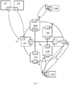
- the Fig. 1 schematically illustrates an example of an AMM type system in which the invention is implemented.
- the AMM-type system of the Fig. 1 comprises a termination system, known as the HES system ("Head End System (HES)" in English terminology) 140.
- the HES system 140 receives electrical consumption measurement information collected by a plurality of meters 120A, 120B, 120C, 120D and 120E (denoted 120A-E) and processes them.
- PLC communications are established between each of said counters and a data concentrator 110.
- the communication system typically comprises a plurality of data concentrators 110, only one being represented on the Fig. 1 .
- To each data concentrator 110 is logically connected a plurality of counters, each data concentrator 110 thus serving as a relay between said counters which are connected to it and the HES system 140.
- a PLC network 101 is thus formed between each data concentrator 110 and the plurality of counters which is connected to it.
- This PLC network 101 is based on an electrical distribution network 100 ( ie . Physical network) serving to supply electricity to the electrical installations that said meters 120 are responsible for monitoring.
- Each counter 120A-E thus comprises a PLC communication interface 111 making it possible to communicate via the PLC network 101.
- each data concentrator 110 comprises such a PLC communication interface 111 making it possible to communicate via the PLC network 101.
- the CPL 101 network conforms to the G3-PLC protocol.
- each data concentrator 110 further comprises a communication interface 113 with a communication network 102, to which the HES system 140 is also connected.
- the HES system 140 thus comprises a communication interface 113 via the communication network 102 allowing it to communicate with a plurality of data concentrators 110.
- the communication network 102 is preferably an IP type network (“Internet Protocol” in English terminology).
- IP type network Internet Protocol
- -saxonne as defined in the normative document RFC 791
- communications between data concentrator 110 and HES system 140 use HTTP requests.
- each counter 120A-E comprises a communication interface 114 with an LPWAN type network of LoRa type, called a LoRa network.
- the LoRa network allows each counter 120A-E to communicate with terminals located within range of said counters, each terminal being connected to the LoRa network via the same communication interface 114.
- Fig. 1 two connected object type terminals 160A and 160B are shown.
- the 120A-E meters and the 160A and 160B terminals communicate according to the LoRaWAN protocol.
- each uplink LoRa frame transmitted in multicast mode by the terminal 160A is received by the counters 120B and 120C.
- Each uplink LoRa frame transmitted in multicast mode by the terminal 160B is received by the counter 120D.
- Each uplink LoRa frame sent by a terminal is intended for a server 150, called a LoRa network server (“LoRa Network Server (LNS)” in English terminology) or LNS server.
- LNS LoRa Network Server
- the LNS server 150 receives the uplink LoRa frames collected by the data concentrator 110 and processes them.
- the LNS server 150 To allow the LNS server 150 to receive the uplink LoRa frames collected by the data concentrator 110, the LNS server 150 includes a communication interface 113 with the communication network 102. In one embodiment, the communications between the data concentrator 110 and the LNS 150 server use HTTP requests.
- each meter having a communication interface 114 implements a LoRa gateway and therefore plays a role similar to a LoRa gateway in a conventional LoRa network vis-à-vis the terminals.
- all the upstream LoRa requests received by a counter 120A-E are not sent back to the LNS 150 server.
- Each entity in the system of Fig. 1 whether it is a data concentrator 110, a counter 120A-E, the HES system 140 and the LNS server 150 comprises a processing module 30 (not shown) allowing these entities to participate in an implementation of the invention .
- the Fig. 2 schematically illustrates a representation of a logic network corresponding to the PLC network implemented on the electrical network 100 illustrated in Fig. 1 .
- each counter 120A-E is connected to a data concentrator 110.
- certain counters such as the counters 120A and 120D are connected directly to the data concentrator 110 while other counters , such as counters 120B, 120C, and 120E are indirectly connected to data concentrator 110 through another meter.
- the 120A and 120D meters can communicate directly with the data concentrator 110.
- each frame conforming to the G3-PLC standard, called G3-PLC frame hereinafter, sent by the 120B, 120C and 120E meters must pass through the counter 120A to reach the data concentrator 110.
- a parent / child hierarchy is therefore created between certain counters.
- the counter 120A is related to the counters 120B, 120C and 120E, which are themselves children of the counter 120A.
- each uplink LoRa frame sent by the terminal 160A is received by the counters 120B and 120C. Consequently, when an uplink LoRa frame is sent by the terminal 160A, it is received by the counter 120B which relays it to the counter 120A and by the counter 120C which also relays it to the counter 120A. The same uplink LoRa frame is therefore received twice by the counter 120A.
- each LoRa gateway receiving an uplink LoRa frame relays it to an LNS server with which it is connected. A LoRa gateway does not care whether one or more other LoRa gateways relayed the same uplink LoRa frame.
- a LoRa gateway receiving an uplink LoRa frame has no way of knowing whether this uplink LoRa frame has been received and relayed to the LNS server by another LoRa gateway.
- the situation is different when the Lora gateway is integrated into a meter such as 120A-E meters.
- some counters such as counter 120A, due to the organization according to a parent / child hierarchy of counters in the AMM type system, receive the same frame several times.
- a counter can know that it is receiving the same uplink LoRa frame multiple times.
- the Fig. 3 schematically illustrates an example of the hardware architecture of the processing module 30.
- the processing module 30 then comprises, connected by a communication bus 300: a processor or CPU 301; a random access memory RAM 302; a ROM read only memory 303; a storage unit or a storage medium reader, such as an SD card reader 304; a set of communication interfaces 305 allowing the processing module 30 to communicate with other entities of the system of the Fig. 1 .
- the set of communication interfaces 305 comprises the communication interface 111 to the PLC network 101 and the communication interface 114 to an LPWAN network.
- the set of communication interfaces 305 comprises the communication interface 111 to the PLC network 101 and the communication interface 113 to the communication network 102.
- the set of communication interfaces 305 includes the communication interface 113 to the network 102.
- the set of communication interfaces 305 comprises the communication interface 113 to the network 102.
- the set of communication interfaces 305 comprises the communication interface 114 to the LPWAN network.
- Processor 301 is capable of executing instructions loaded into RAM 302 from ROM 303, external memory (not shown), storage media, such as an SD card, or an SD card. communication network.
- entity ie data concentrator 110, counter 120A-E, HES system 140, LNS server 150, terminal 160A or 160B
- processor 301 is able to read RAM 302 instructions and execute them.
- These instructions form a computer program causing the implementation, by the processor 301 of a described in relation to the Fig. 4 .
- All or part of the process described in relation to the Fig. 4 can be implemented in software form by executing a set of instructions by a programmable machine, such as a DSP (“Digital Signal Processor”) or a microcontroller, or can be implemented in hardware form by a machine or a dedicated component, such as an FPGA (“Field-Programmable Gate Array” in English terminology) or an ASIC (“Application-Specific Integrated Circuit” in English terminology).
- a programmable machine such as a DSP (“Digital Signal Processor”) or a microcontroller
- a dedicated component such as an FPGA (“Field-Programmable Gate Array” in English terminology) or an ASIC (“Application-Specific Integrated Circuit” in English terminology).
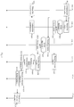
- the Fig. 4 schematically illustrates an example of implementation in an AMM type system of a method making it possible to route frames sent by terminals on an LPWAN type network.
- the processing module 30 of the terminal 160A causes a sending of an Upstream LoRa frame.
- This uplink LoRa frame is transmitted in multicast mode via the communication interface 114 of the terminal 160A.
- the upstream LoRa frame includes an identifier of the terminal 160A in the form of a DevAddr address.
- the processing module 30 of the counter 120B detects a reception by the counter 120B on its communication interface 114, of the upstream LoRa frame.
- the upstream LoRa frame when it is sent by the terminal 160A, sent frame and the upstream LoRa frame when it is received by a counter, for example here the counter 120B, frame received.
- a step 403 in order to decide whether the frame received by the counter 120B must be relayed, the processing module 30 of the counter 120B determines whether this frame meets a first predetermined criterion.
- the predetermined criterion consists in systematically selecting the frame corresponding to said transmitted frame received first by counter 120B.
- the processing module 30 puts itself on standby for a predetermined period TEMPO following the first reception of a frame corresponding to the same frame transmitted.
- the predetermined period TEMPO is for example “200” ms.
- the predetermined criterion consists in randomly selecting a frame from among the frames corresponding to said transmitted frame received by the counter 120B during the predetermined period TEMPO.
- the processing module 30 puts itself on standby for the predetermined period TEMPO following the first reception of a frame corresponding to the same frame transmitted.
- the predetermined criterion consists in selecting the frame offering a better reception quality among the frames corresponding to said transmitted frame received during the predetermined period TEMPO.
- the counter 120B only receives the frame once sent by the terminal 160A. Therefore, regardless of the embodiment, the only received frame is selected to be relayed.
- a step 404 the processing module 30 of the counter 120B encapsulates the frame received in a G3-PLC frame and transmits this G3-PLC frame towards the data concentrator 110.
- the counter 120B therefore transmits the G3-PLC frame to the 120A meter.
- the G3-PLC frame sent by the counter 120B is called hereafter the first G3-PLC frame.
- the Fig. 5 schematically illustrates an encapsulation of an upstream LoRa frame in a G3-PLC frame.
- the frame represented in the Fig. 5 is therefore a frame conforming to the G3-PLC standard.
- This G3-PLC frame includes in a field 56, a G3-PLC header, in a field 55, a 6LowPAN header (Low power IPv6 wireless local network: "IPv6 Low power Wireless Personal Area Networks" in English terminology) , in a field 54, an IPv6 header (Internet Protocol version 6: “Internet Protocol version 6” in English terminology) and in a field 53, a UDP header (User datagram protocol: “User Datagram Protocol” in English terminology -saxonne).
- the G3-PLC frame further comprises a first sub-part 51 comprising the encapsulated uplink LoRa frame and a second sub-part 52.
- the sub-parts 51 and 52 form a useful part of the G3-PLC frame.
- the second sub-part 52 is intended to receive identifiers from each counter having directly received ( ie through a network interface 114) the encapsulated LoRa frame.
- each LoRa gateway implemented by a counter has an IP address (Internet Protocol: “Internet Protocol” in English terminology).
- the identifier of a counter having received the upstream LoRa frame is in this case, the IP address of the LoRa gateway implemented by this counter.
- a LoRaWAN transport service by G3-PLC implemented by the meter is associated with a UDP port number.
- the identifier of a counter having directly received the upstream LoRa frame is an IP address of the counter and the UDP port number that associated with the LoRaWAN transport service by G3-PLC.
- the source IP address conveyed by the IPv6 transport protocol in field 54 is still that of the counter, there is no need to transmit an IP address in field 52.
- the counter 120B stores in the subpart 52 the identifier of the counter 120B.
- the subpart 52 in addition to storing an identifier of each counter having received the uplink LoRa frame, stores for each counter having received the uplink LoRa frame, information representative of a quality of reception of said frame. LoRa rising by said meter.
- the quality information is for example a signal to noise ratio (SNR) in English terminology) and / or an indication on the strength of the received signal (“received signal strength indication (RSSI)" in English terminology).
- the subpart 52 comprises information representative of the quality of reception of the frame sent by the terminal 160A by the counter 120B.
- the processing module 30 of the counter 120C detects a reception by the counter 120C on its communication interface 114, of the frame sent by the terminal 160A.
- a step 407 the processing module 30 of the counter 120C applies a step identical to the step 403.
- the result of the step 407 is then identical to the result of the step 403, since the processing module 30 of the counter 120C selects the only frame received and relays this frame during step 408 towards the data concentrator 110 in a G3-PLC frame.
- the G3-PLC frame sent by the counter 120C is called hereafter the second G3-PLC frame.
- the second G3-PLC frame uses the frame format described in relation to the Fig. 5 .
- it includes the same uplink LoRa frame as the first G3-PLC frame.
- sub-part 52 it includes the identifier of the counter 120C.
- the subpart 52 also comprises information representative of a quality of reception of said upstream LoRa frame by the counter 120C.
- the processing module 30 of counter 120A respectively receives the first frame G3-PLC and the second frame G3-PLC on its communication interface 111.
- a step 410 the processing module 30 of the counter 120A applies a step identical to the steps 403 and 407.
- steps 403 and 407 were executed in a context where the counters 120B and 120C each received only one frame corresponding to the frame transmitted, during step 410, the counter 120A receives two frames corresponding to the frame transmitted.
- the processing module 30 of the counter 120A selects the first frame received corresponding to the frame sent on receipt of this frame.
- the frame received during step 405 is therefore selected to be relayed.
- the processing module 30 of the counter 120A randomly selects a frame from among the frames corresponding to the frame issued that he received. For example, the processing module 30 of the counter 120A selects the frame received during step 405 ( ie the first frame G3-PLC).
- the processing module 30 of the counter 120A selects the frame offering the best reception quality among the frames corresponding to the transmitted frame that it has received. To do this, the processing module 30 of the counter 120A uses the information representative of a reception quality contained in the sub-part 52 of each received G3-PLC frame ( ie the first and the second G3-PLC frame). For example, the processing module 30 of counter 120A selects the frame received during step 409 ( ie the second frame G3-PLC).
- the processing module rejects at least a subset of the frames of the plurality different from the frame selected during step 410, each frame of the subset being selected according to a second predetermined criterion.
- the second predetermined criterion consists of rejecting each frame of the different plurality of the frame selected in step 410.
- each counter 120A-E only relays a single frame. corresponding to the frame sent to the data concentrator 110.
- the second predetermined criterion consists in randomly selecting a predefined quantity of frames from among the frames of the plurality other than the frame selected during step 410, all the other frames of the plurality being discarded.
- the processing module 30 of the counter 120A randomly selects a frame from among the frames of the plurality different from the frame selected during step 410.
- each counter 120A-E relays two corresponding frames. to the frame sent to the data concentrator 110.
- the second predetermined criterion consists in selecting a predefined quantity of frames offering a better transmission quality among the frames of the plurality different from the frame selected during step 410, all the other frames of the plurality being rejected.
- the processing module 30 of the counter 120A uses the information representative of a quality of reception contained in the subpart 52 of each G3-PLC frame received. For example, the processing module 30 of the counter 120A selects a frame from among the frames of the plurality different from the frame selected during step 410.
- each counter 120A-E relays two corresponding frames. to the frame sent to the data concentrator 110. For example, each counter relays the frames offering the two best transmission qualities among the frames of the plurality.
- each relayed frame comprises the uplink LoRa frame transmitted by the terminal 160A during step 401 in its sub-part 51.
- each relayed frame comprises in its sub-part. -part 52, the identifier of each counter having directly received the upstream LoRa frame (here this corresponds to the counters 120B and 120C).
- the sub-part 52 further comprises, for each counter having directly received the upstream LoRa frame transmitted by the terminal 160A, information representative of a quality of reception of said frame by the counter.
- each relayed G3-PLC frame includes information representative of the quality of reception of the upstream LoRa frame by the counter 120B and information representative of the quality of reception of the upward LoRa frame by the counter 120C.
- the processing module 30 of the data concentrator 110 detects that the data concentrator 110 has received at least one G3-PLC frame. During step 413, the processing module 30 determines for each G3-PLC frame received, if the G3-PLC frame contains metrology data emanating from a counter or if it contains data conforming to the LoRaWAN protocol. To do this, the processing module 30 of the data concentrator 110 determines whether the useful part of the G3-PLC frame contains sub-parts 51 and 52. When the G3-PLC frame comprises metrology data, the useful part of the G3-PLC frame is extracted and encapsulated in an HTTP frame which is transmitted towards the HES 140 system. When the G3-PLC frame comprises sub-parts 51 and 52, the useful part of the G3-PLC frame is extracted and encapsulated in an HTTP frame which is transmitted to the LNS server 150 in a step 414.
- the Fig. 6 schematically illustrates an encapsulation of an uplink LoRa frame in an HTTP frame.
- the HTTP frame includes in a field 66 for example an Ethernet header, in a field 65 an IP header (IPv4 or IPv6), in a field 64 a TCP header (transmission control protocol (TCP) "in English terminology) and in a field 63 an HTTP header.
- IPv4 or IPv6 IP header
- TCP header transmission control protocol
- sub-part 51 and a sub-part 62 which is identical to the sub-part 52 in the case where we do not associate a UDP port number with the transport service of LoRaWAN by G3-PLC (subpart 62 therefore includes the IP address of the LoRa gateway implemented by the meter which relayed the upstream LoRa frame), and which includes the IP address of the meter implementing the LoRa gateway in the case where a UDP port number is associated with the LoRaWAN transport service by G3-PLC implemented by the counter which relayed the upstream LoRa frame.
- TLS protocol Transport Layer Security
- HTTP which corresponds to HTTPS (“Hyper Text Transfer Protocol Secure” in English terminology
- the processing module 30 of the LNS server 150 detects that the LNS server 150 has received an HTTP frame containing data conforming to the LoRaWAN protocol and processes this data.
- the message exchanges between a terminal and an LNS server are bidirectional.
- An LNS server can for example acknowledge an uplink LoRa frame.
- the LNS server must designate among the LoRa gateways having received the uplink LoRa frame, the LoRa gateway to be used to relay a response. to the message contained in the upstream LoRa frame.
- the response is transmitted from the LNS server to the designated LoRa gateway in an HTTP request, then point to point, from the designated LoRa gateway to the terminal in a downlink LoRa frame conforming to the LoRaWAN protocol.
- AMM systems have data transfer times which are incompatible with the time constraints allocated by the LoRaWAN protocol to a terminal for receiving an acknowledgment after sending by said terminal an uplink LoRa frame.
- the processing module 30 of the LNS server 110 designates, for each terminal of which it is aware, a counter among the counters capable of relaying uplink LoRa frames for said terminal. This designation can be done, for example, during a procedure for connecting a terminal to a LoRa network.
- the upstream LoRa frame transmitted during step 401 by the terminal 160A is a connection request frame (“Join Request” in English terminology).
- the method described in relation to the Fig. 4 is a start of a connection procedure corresponding to a connection request phase.
- the LNS server 150 therefore receives, in the sub-part 51 of at least one HTTP frame, a connection request frame. Moreover, in the sub-part 52, the LNS server 150 receives an identifier of the counters 120B and 120C. In one embodiment, the processing module 30 of the LNS server 150 randomly chooses a counter from among the counters having an identifier in the subpart 52. In another embodiment, when the subpart 52 also includes representative information of reception qualities of the uplink LoRa frame included in the subpart 51, the processing module 30 of the LNS server 150 chooses the counter associated with the best quality representative information. For example, the processing module 30 of the LNS server 150 chooses the counter 120B.
- the designated counter is then used for each transmission of a downlink LoRa frame by the LNS server 150 to the terminal 160A.
- the designation of the counter 120B can be final or updated periodically, for example, every "24" hours.
- the processing module 30 of the LNS server 150 relies on the content of the subpart 52 associated with any uplink LoRa frame that it receives, without this uplink LoRa frame necessarily being a connection request frame.
- connection authorization frame (“JOIN ACCEPT” in English terminology).
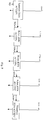
- the Fig. 9 schematically illustrates a connection authorization procedure.
- a step 901 the processing module of the LNS server 150 generates a downlink LoRa frame containing a connection authorization, called a connection authorization frame, intended for the device 160A, encapsulates the connection authorization frame in an HTTP frame and causes the LNS server 150 to transmit the HTTP frame to the data concentrator 110.
- the Fig. 8 schematically illustrates an encapsulation of a downlink LoRa frame in an HTTP frame.
- Subpart 51 comprises the connection authorization frame.
- the HTTP frame further comprises a sub-part 82.
- the sub-part 82 comprises the identifier of the designated counter. In the example of Fig. 9 , this is counter 120B.
- the subpart 82 includes a desired date of transmission of the downlink LoRa frame by the designated counter ( ie the counter 120B). This issue date is a date relative to a date of receipt of an upstream LoRa frame by the designated counter.
- the data concentrator 110 receives the HTTP frame.
- the processing module 30 of the data concentrator 110 extracts the useful part of the HTTP frame (ie the sub-parts 51 and 82) and forms a G3-PLC frame using this useful part.
- the Fig. 7 schematically illustrates an encapsulation of a downlink LoRa frame in a G3-PLC frame.
- the fields 53, 54, 55 and 56 are found in the G3-PLC frame.
- the subpart 51 comprises the downlink LoRa frame.
- a sub-part 72 includes the desired date of transmission of the downlink LoRa frame by the designated counter indicated in sub-part 82.
- step 903 the processing module 30 of the data concentrator 110 reads the address of the counter designated in subpart 82 (or 72) and determines that to reach the designated counter ( ie, the counter 120B), it must transmit the G3-PLC frame it has formed to counter 120A. The processing module 30 of the data concentrator 110 then causes the sending of the G3-PLC frame to the counter 120A.
- the counter 120A receives the G3-PLC frame. During step 904, the counter 120A relays this frame in the direction of the counter 120B.
- a step 905 the processing module 30 of the counter 120B detects that the counter 120B has received the G3-PLC frame and extracts the descending LoRa frame from the G3-PLC frame.
- the processing module 30 of the counter 120B waits for a reception of an upstream LoRa frame from the terminal 160A.
- the processing module 30 of counter 120B detects a reception of an upstream LoRa frame, it notes the date of reception of this upstream LoRa frame, adds the value of the desired transmission date contained in the G3-PLC frame received during from step 905 to the date of reception to obtain an effective date of transmission, and transmits the LoRa frame descending to terminal 160A on the effective date of transmission thus calculated.
- the downlink LoRa frame also contains an acknowledgment of the last upstream LoRa frame received.
- the processing module 30 of the counter 120B determines that its identifier has been inserted into the subpart 72 and deduces from this that it has been designated to transmit each message coming from the LNS server 150 and intended for the user. terminal 160A.
- the processing module 30 of the counter 120A determines that it must from now on acknowledge each LoRa frame sent by the terminal 160A.
- the device 160A receives the downlink LoRa frame.
- the downlink LoRa frame is therefore a connection authorization.
- a similar process is applied for any other frame transmitted by the LNS server 150 to the terminal 160A.
- the uplink LoRa frame sent by the terminal 160A is a frame containing a message intended for the LNS server 150.
- a connection procedure with transmission of a connection request frame by the terminal 160A and transmission of a connection authorization by the LNS 150 server has been performed beforehand.
- the LNS server 150 does not acknowledge the upstream LoRa frames, but delegates the charge of carrying out the acknowledgments to a counter that it has designated.
- the connection procedure carried out previously and described in relation to the Figs. 4 and 9 made it possible to designate the counter 120B to carry out the acknowledgments of the upstream LoRa frames coming from the terminal 160A.
- a terminal and the LNS server each manage an FcntUP variable and an FcntDOWN variable.
- the terminal's FcntUP and FcntDOWN variables are called FcntUP_T and FcntDown_T respectively. All these variables are either on 32 bit (32 bit mode: usual case), or on 16 bit (16 bit mode: variant). On the other hand, only the low order 16 bits are transported in the LoRAWAN frames whatever the mode.
- the variables FcntUP and FcntDOWN of the LNS server are subsequently called FcntUP_S and FcntDown_S respectively.
- the LNS server manages a couple of variables FcntUP_S and FcntDown_S for each terminal of which it is aware.
- the FcntUP_T variable is incremented by one each time the terminal transmits an upstream LoRa frame.
- the FcntDown_T variable is updated each time the terminal receives a downlink LoRa frame.
- the terminal takes into account the value on 16 bit received in the frame and manages in increments of the FcntDown_T vary depending on this value of 16 bit received, in particular concerning the 17th bit from the right of the variable of 32 bit.
- the terminal copies the 16-bit value received in the frame into its local variable.
- the FcntUP_S variable is managed in exactly the same way by the LNS server as the FcntDown_T variable of the terminal, each time the LNS server receives an upstream LoRa frame from the terminal with which the variable is associated.
- the FcntDown_S variable is incremented by one each time the LNS server transmits a downlink LoRa frame to the terminal with which the variable is associated.
- the variables FcntUP_T, FcntDown_T, FcntUP_S and FcntDown S are set to zero.
- an LNS server When an LNS server transmits a downlink LoRa frame, it inserts the value of its FcntDown_S counter into this frame.
- the LNS server receives from a terminal an uplink LoRa frame containing a FcntUP_T variable whose value is less than the value of the FcntUP_S variable associated with said terminal, it rejects the uplink Lora frame.
- a terminal receives from the LNS server a descending LoRa frame containing an FcntDown_S variable whose value is less than the value of the FcntDown_T variable, it rejects the descending LoRa frame.
- a counter designated by the LNS server 150 to transmit downlink Lora frames to a terminal and to acknowledge the upstream LoRa frames coming from this terminal is also delegated the management of the variables FcntUP_S and FcntDown_S for said terminal instead of the LNS 150 server.
- the processing module 30 of the counter 120B must manage the variables FcntUP_S and FcntDown_S associated with the terminal 160A.
- the processing module 30 increments the value of the variable FcntDown_S by one and inserts this value into the frame LoRa descending or in the acknowledgment frame.
- the counter 120B receives an upstream LoRa frame from the terminal 160A, it updates the variable FcntUP_S as indicated above in the case of a conventional LoRa network.
- the processing module 30 of the counter 120B rejects said frame.
- the processing module 30 of the counter 120B executes a step 418.
- the processing module 30 of counter 160A generates an acknowledgment frame, increments the value of the variables FcntUP_S and FcntDown_S by one and inserts the value of the variable FcntDown_S in the acknowledgment frame.
- the acknowledgment frame is then transmitted to terminal 160A. It is assumed that each counter in charge of acknowledging uplink LoRa frames instead of the LNS 150 server, has previously stored LoRaWAN protocol information such as an NtwSEndKey and an SNwkSIntKey, each of these keys being unique for each terminal .
- the key NtwSEndKey is used to encode a useful part (“payload” in English terminology) of the acknowledgment frame.
- the SNwkSIntKey key is used to encode the MIC (message integrity code: “message integrity code”) part of the acknowledgment frame.
- the terminal 160A receives the acknowledgment frame and checks that the value of the variable FcntDown_S is greater than the value of the variable FcntDown_T. If the value of the FcntDown_S variable is greater than the value of the FcntDown_T variable, the terminal 160A accepts the acknowledgment frame and increments the value of the FcntDown_T variable by one.
- each counter 120A-E comprises an interface having a communication interface 114 and implements a LoRa gateway.
- all of the 120A-E counters implement a LoRa gateway, but do not necessarily include a communication interface 114.
- a 120A-E counter can therefore implement a Lora gateway without being able to receive or transmit frames.
- LoRa the counter 120A does not include a communication interface 114 but implements a LoRa gateway which allows it to execute in particular steps 405, 409, 410, 411, 412 and 904.
- some counters do not include a communication interface 114 and do not implement a LoRa gateway. These counters can then be intermediate counters between two counters implementing a LoRa gateway. These counters then only relay G3-PLC frames, regardless of the content of these frames.
- the LNS server 150 When the communication system has a plurality of data concentrators 110, it is possible for the LNS server 150 to receive several HTTP frames encapsulating the same uplink LoRa frame from several different data concentrators 110.
- the sub-parts 62 of each HTTP frame received contain information representative of sets of counters having received the different uplink LoRa frame.
- the processing module 30 of the LNS server 150 takes into account all the HTTP frames containing the same uplink LoRa frame.
- the processing module 30 of the LNS server 150 must designate a counter for relaying frames to a terminal or for acknowledging frames, it designates it from among the counters indicated in sub-parts 62 of each HTTP frame received.
Landscapes
- Engineering & Computer Science (AREA)
- Computer Networks & Wireless Communication (AREA)
- Signal Processing (AREA)
- Power Engineering (AREA)
- Computer Security & Cryptography (AREA)
- Mobile Radio Communication Systems (AREA)
- Telephonic Communication Services (AREA)
- Small-Scale Networks (AREA)
- Communication Control (AREA)
Claims (11)
- Verfahren zum Transportieren von Frames, die von Endgeräten gesendet werden, an ein Netzwerk vom Typ LPWAN (Low Power Wide Area Network) über ein erstes Powerline-Kommunikationsnetzwerk (101), als AMM-Netzwerk bezeichnet, eines Systems zur automatischen Verwaltung von Ablesungen einer Vielzahl von elektrischen Zählern (120A, 120B, 120C, 120D, 120E), als Zähler bezeichnet, wobei die Zähler der Vielzahl von Zählern über das AMM-Netzwerk mit mindestens einem Datenkonzentrator (110) verbunden sind, wobei jeder Datenkonzentrator über ein zweites Netzwerk (102) mit einem Server (150) verbunden ist und als Vermittler zwischen den Zählern und dem Server dient, dadurch gekennzeichnet, dass das Verfahren von einem Zähler der Vielzahl von Zählern ausgeführt wird und Folgendes beinhaltet:Empfangen (402) mindestens eines Frames, der mit einem Kommunikationsprotokoll, das für die Netzwerke vom Typ LPWAN geeignet ist, übereinstimmt, wobei jeder empfangene Frame einem gleichen Frame, der durch ein Endgerät an das Netzwerk vom Typ LPWAN gesendet wird, entspricht;Vermitteln (404) eines empfangenen Frames, als erster Frame bezeichnet, der dem an den Server gesendeten Frame entspricht, wobei der erste Frame gemäß einem vorgegebenen ersten Kriterium ausgewählt (403) wird;wenn eine Vielzahl von Frames, die dem gesendeten Frame entsprechen, empfangen wird, Ablehnen mindestens eines Teilsatzes der Frames der Vielzahl, die sich von dem ersten Frame unterscheiden, wobei jeder Frame des Teilsatzes gemäß einem vorgegebenen zweiten Kriterium ausgewählt wird.
- Verfahren nach Anspruch 1, dadurch gekennzeichnet, dass das vorgegebene erste Kriterium darin besteht, den zuerst empfangenen Frame, der dem gesendeten Frame entspricht, auszuwählen oder den ersten Frame aus den innerhalb eines vorgegebenen Zeitraums empfangenen Frames, die dem gesendeten Frame entsprechen, zufällig auszuwählen oder den ersten Frame mit der besseren Empfangsqualität aus den während eines vorgegebenen Zeitraums empfangenen Frames, die dem gesendeten Frame entsprechen, auszuwählen.
- Verfahren nach Anspruch 1 oder 2, dadurch gekennzeichnet, dass das vorgegebene zweite Kriterium darin besteht, jeden Frame der Vielzahl, der sich von dem ersten Frame unterscheidet, abzulehnen oder eine vordefinierte Menge von Frames aus den Frames der Vielzahl, die sich von dem ersten Frame unterscheiden, zufällig auszuwählen, wobei alle anderen Frames der Vielzahl abgelehnt werden, oder eine vordefinierte Menge von Frames mit einer besseren Übertragungsqualität aus den Frames der Vielzahl, die sich von dem ersten Frame unterscheiden, auszuwählen, wobei alle anderen Frames der Vielzahl abgelehnt werden.
- Verfahren nach Anspruch 1, 2 oder 3, dadurch gekennzeichnet, dass der Zähler einen Quittierungs-Frame an das Endgerät überträgt, um den gesendeten Frame zu quittieren, wenn er vom Server designiert wurde, jeden durch das Endgerät gesendeten Frame zu quittieren.
- Vorrichtung vom Typ eines elektrischen Zählers, die in einem System, als AMM-System bezeichnet, zur automatischen Verwaltung von Ablesungen einer Vielzahl von elektrischen Zählern (120A, 120B, 120C, 120D, 120E) enthalten ist, wobei die Zähler der Vielzahl von Zählern über ein erstes Powerline-Netzwerk (101) mit mindestens einem Datenkonzentrator (110) verbunden sind, wobei jeder Datenkonzentrator über ein zweites Netzwerk (102) mit einem Server (150) verbunden ist und als Vermittler zwischen den Zählern und dem Server dient, dadurch gekennzeichnet, dass die Vorrichtung Folgendes beinhaltet:Vermittlungsmittel zum Vermitteln, an den Server, eines durch die Vorrichtung empfangenen Frames, als erster Frame bezeichnet, der einem Frame entspricht, der mit einem Kommunikationsprotokoll, das für die Netzwerke vom Typ LPWAN (Low Power Wide Area Network) geeignet ist, übereinstimmt, gesendet durch ein Endgerät an ein Netzwerk vom Typ LPWAN, wobei der erste Frame gemäß einem vorgegebenen ersten Kriterium ausgewählt wird; undAblehnungsmittel, die eingesetzt werden, wenn eine Vielzahl von Frames, die dem ersten gesendeten Frame entsprechen, empfangen wird, um mindestens einen Teilsatz der Frames der Vielzahl, die sich von dem ersten Frame unterscheiden, abzulehnen,wobei jeder Frame des Teilsatzes gemäß einem vorgegebenen zweiten Kriterium ausgewählt wird.
- Vorrichtung nach Anspruch 5, dadurch gekennzeichnet, dass sie eine Kommunikationsschnittstelle (114) zu einem Netzwerk vom Typ LPWAN beinhaltet, die es dem Zähler gestattet, Frames, die mit einem Kommunikationsprotokoll, das für die Netzwerke vom Typ LPWAN geeignet ist, übereinstimmen, zu empfangen.
- System, als AMM-System bezeichnet, zur automatischen Verwaltung von Ablesungen von elektrischen Zählern, als Zähler bezeichnet, wobei das System eine Vielzahl von Zählern (120A, 120B, 120C, 120D, 120E), mindestens einen Datenkonzentrator (110) und einen Server (150) beinhaltet, wobei die Zähler der Vielzahl von Zählern über ein erstes Powerline-Netzwerk (101) mit einem Datenkonzentrator verbunden sind, wobei jeder Datenkonzentrator über ein zweites Netzwerk (102) mit dem Server verbunden ist und als Vermittler zwischen den Zählern und dem Server dient, dadurch gekennzeichnet, dass mindestens ein Zähler des AMM-Systems eine Vorrichtung nach Anspruch 6 ist, als LPWAN-Zähler bezeichnet.
- System nach Anspruch 7, dadurch gekennzeichnet, dass mindestens ein Zähler des AMM-Systems eine Vorrichtung nach Anspruch 5 ist.
- System nach Anspruch 7 oder 8, dadurch gekennzeichnet, dass, wenn das AMM-System eine Vielzahl von LPWAN-Zählern beinhaltet, der Server Mittel beinhaltet, um für jedes Endgerät, das mit einem der LPWAN-Zähler kommuniziert, zu bestimmen, welcher LPWAN-Zähler, der mit dem Endgerät kommuniziert, jeden durch das Endgerät gesendeten Frame quittieren muss.
- Computerprogramm, dadurch gekennzeichnet, dass es Anweisungen zur Umsetzung des Verfahrens nach einem der Ansprüche 1 bis 4 durch eine Vorrichtung beinhaltet, wenn das Programm durch einen Prozessor der Vorrichtung ausgeführt wird.
- Speichermittel, dadurch gekennzeichnet, dass sie ein Computerprogramm speichern, das Anweisungen zur Umsetzung des Verfahrens nach einem der Ansprüche 1 bis 4 durch eine Vorrichtung beinhaltet, wenn das Programm durch einen Prozessor der Vorrichtung ausgeführt wird.
Applications Claiming Priority (1)
| Application Number | Priority Date | Filing Date | Title |
|---|---|---|---|
| FR1855822A FR3083408B1 (fr) | 2018-06-28 | 2018-06-28 | Procede permettant de transporter des trames lora sur un reseau cpl. |
Publications (2)
| Publication Number | Publication Date |
|---|---|
| EP3588971A1 EP3588971A1 (de) | 2020-01-01 |
| EP3588971B1 true EP3588971B1 (de) | 2021-02-24 |
Family
ID=65031301
Family Applications (1)
| Application Number | Title | Priority Date | Filing Date |
|---|---|---|---|
| EP19180743.7A Active EP3588971B1 (de) | 2018-06-28 | 2019-06-18 | Verfahren zum transportieren von lora frames in ein cpl-netzwerk |
Country Status (4)
| Country | Link |
|---|---|
| US (1) | US11165465B2 (de) |
| EP (1) | EP3588971B1 (de) |
| CN (1) | CN110661774B (de) |
| FR (1) | FR3083408B1 (de) |
Families Citing this family (5)
| Publication number | Priority date | Publication date | Assignee | Title |
|---|---|---|---|---|
| TWI723534B (zh) * | 2019-09-09 | 2021-04-01 | 優必闊科技股份有限公司 | 資料集中裝置以及用於進階計量之系統 |
| CN113316033B (zh) * | 2021-05-31 | 2022-07-22 | 宁波迦南智能电气股份有限公司 | 一种基于lora层次拓扑网络的无线抄表方法 |
| DE102021124959A1 (de) | 2021-09-27 | 2023-03-30 | Diehl Metering Systems Gmbh | Anordnung und Verfahren zum Betrieb einer Netzwerk-Infrastruktur |
| CN114614948A (zh) * | 2022-03-16 | 2022-06-10 | 广州物联网研究院 | 一种LoRa组网方法及系统 |
| US20250392348A1 (en) * | 2024-06-19 | 2025-12-25 | Tyco Fire & Security Gmbh | Repeater module and methods for a building network |
Family Cites Families (19)
| Publication number | Priority date | Publication date | Assignee | Title |
|---|---|---|---|---|
| CN1767465A (zh) * | 2004-10-27 | 2006-05-03 | 乐金电子(天津)电器有限公司 | 家庭网络系统 |
| CN101236693B (zh) * | 2007-02-01 | 2011-08-10 | 上海久隆电力(集团)有限公司 | 一种智能抄表系统 |
| CN102401848B (zh) * | 2010-09-08 | 2014-05-07 | 国基电子(上海)有限公司 | 电表及其通信中继方法 |
| US20140092753A1 (en) * | 2012-09-28 | 2014-04-03 | Cisco Technology, Inc. | Traffic-based quality of service (qos) monitoring in highly constrained networks |
| US9014056B2 (en) * | 2012-12-18 | 2015-04-21 | Qualcomm Incorporated | Bridging network devices in a hybrid communication network |
| US9198198B2 (en) * | 2013-04-16 | 2015-11-24 | Texas Instruments Incorporated | Efficient fairness allocation in powerline CSMA/CA protocols |
| JP5954248B2 (ja) * | 2013-04-30 | 2016-07-20 | 日立金属株式会社 | ネットワーク中継装置 |
| CN104104412B (zh) * | 2014-07-28 | 2016-09-14 | 科大智能电气技术有限公司 | 一种基于dma的电力线网络系统及其通讯方法 |
| CN104243130B (zh) * | 2014-09-26 | 2019-03-19 | 武汉晟联智融微电子科技有限公司 | 一种plc物理层时钟同步方法 |
| KR20190143472A (ko) * | 2015-01-28 | 2019-12-30 | 인터디지탈 패튼 홀딩스, 인크 | 비면허 대역에서의 lte용 업링크 동작 |
| US20160227532A1 (en) * | 2015-02-02 | 2016-08-04 | Shahrnaz Azizi | Systems, methods, and devices for signal classification in wireless networks |
| US9977415B2 (en) * | 2015-07-03 | 2018-05-22 | Afero, Inc. | System and method for virtual internet of things (IOT) devices and hubs |
| FR3039308B1 (fr) * | 2015-07-21 | 2017-08-18 | Sagemcom Energy & Telecom Sas | Transmission de donnees chiffrees depuis des compteurs electriques intelligents |
| CN105959288A (zh) * | 2016-05-27 | 2016-09-21 | 姹や寒 | 一种电力电网系统中的网络协议转换及其相互通讯方法 |
| CN105915390A (zh) * | 2016-06-07 | 2016-08-31 | 中电华瑞技术有限公司 | 一种电力线网络中根节点网络协调方法和系统 |
| FR3056056B1 (fr) * | 2016-09-12 | 2018-09-21 | Sagemcom Energy & Telecom Sas | Procede de detection de reemission d'une trame |
| KR101787284B1 (ko) * | 2016-10-11 | 2017-10-18 | 한국전력공사 | 데이터 집중 장치, 전력량계 및 이의 동작 방법 |
| CN107465608B (zh) * | 2017-08-17 | 2019-03-12 | 浙江比弦物联科技有限公司 | 基于NB-IoT的物联网多功能网关 |
| FR3084233B1 (fr) * | 2018-07-18 | 2022-01-28 | Sagemcom Energy & Telecom Sas | Dispositif permettant de transporter des trames lora sur un reseau cpl. |
-
2018
- 2018-06-28 FR FR1855822A patent/FR3083408B1/fr not_active Expired - Fee Related
-
2019
- 2019-06-18 EP EP19180743.7A patent/EP3588971B1/de active Active
- 2019-06-20 US US16/447,331 patent/US11165465B2/en active Active
- 2019-06-28 CN CN201910576604.3A patent/CN110661774B/zh active Active
Non-Patent Citations (1)
| Title |
|---|
| None * |
Also Published As
| Publication number | Publication date |
|---|---|
| CN110661774A (zh) | 2020-01-07 |
| EP3588971A1 (de) | 2020-01-01 |
| US11165465B2 (en) | 2021-11-02 |
| US20200007191A1 (en) | 2020-01-02 |
| FR3083408A1 (fr) | 2020-01-03 |
| FR3083408B1 (fr) | 2020-09-18 |
| CN110661774B (zh) | 2023-04-18 |
Similar Documents
| Publication | Publication Date | Title |
|---|---|---|
| EP3598801B1 (de) | Verfahren zum transportieren von lora frames in ein cpl-netzwerk | |
| EP3588971B1 (de) | Verfahren zum transportieren von lora frames in ein cpl-netzwerk | |
| EP3629541B1 (de) | Roaming-verwaltungsverfahren durch multi-netzwerk-transfer | |
| EP3635989B1 (de) | Datenübertragung zwischen einem endgerät und einem zugehörigen server | |
| EP3777102B1 (de) | Datenübertragung von einer verwaltungseinheit zu einem intelligenten stromzähler | |
| EP3549352B1 (de) | Elektrizitätszähler mit einem stromleitungsschnitstelle und zumindest einem radiofrequenzschnitstelle. | |
| EP3782331B1 (de) | Vorrichtung zur verbindung mit einem amm-system | |
| EP2172074A2 (de) | Zugangspunkt und knoten zur steuerung des routings in einem hybridnetzwerk | |
| FR2922398A1 (fr) | Systeme d'interconnexion entre au moins un appareil de communication et au moins un systeme d'information distant et methode d'interconnexion | |
| EP3759936A1 (de) | Verfahren zur übertragung mittels eines intelligenten elektrischen zählers, wobei eine nachricht die erkennung eines fehlers in der elektrischen stromversorgung darstellt | |
| EP3734984B1 (de) | Verfahren zum ablesen von fluidzählern | |
| EP3189652B1 (de) | Verfahren zur weiterleitung von daten zwischen ip-vorrichtungen | |
| FR3055504A1 (fr) | Procede de controle de la charge d'une passerelle de concentration de donnees pour un reseau de communication sans fil | |
| FR2951045A1 (fr) | Procede de gestion de la taille de paquets de donnees d'un flux de donnees, produit programme d'ordinateur, moyen de stockage, et tete de tunnel correspondants. | |
| EP3718372A1 (de) | Verfahren zur herstellung einer vorrichtung mit einer sich über einen hohlraum erstreckenden membran | |
| EP4142171A1 (de) | Übertragungsverfahren und knotenvorrichtung für die implementierung dieses verfahrens | |
| EP1858224A1 (de) | Verfahren zur Einrichtung von virtuellen Privatnetzen und Fernzugriffskontrolle | |
| FR3087610A1 (fr) | Echange de donnees dans une infrastructure des objets connectes | |
| WO2009080924A1 (fr) | Procede pour gerer la transmission de donnees en mode multidiffusion vers une pluralite d'elements de reseau, et element de reseau pour la mise en œuvre du procede |
Legal Events
| Date | Code | Title | Description |
|---|---|---|---|
| PUAI | Public reference made under article 153(3) epc to a published international application that has entered the european phase |
Free format text: ORIGINAL CODE: 0009012 |
|
| STAA | Information on the status of an ep patent application or granted ep patent |
Free format text: STATUS: THE APPLICATION HAS BEEN PUBLISHED |
|
| AK | Designated contracting states |
Kind code of ref document: A1 Designated state(s): AL AT BE BG CH CY CZ DE DK EE ES FI FR GB GR HR HU IE IS IT LI LT LU LV MC MK MT NL NO PL PT RO RS SE SI SK SM TR |
|
| AX | Request for extension of the european patent |
Extension state: BA ME |
|
| STAA | Information on the status of an ep patent application or granted ep patent |
Free format text: STATUS: REQUEST FOR EXAMINATION WAS MADE |
|
| 17P | Request for examination filed |
Effective date: 20200630 |
|
| RBV | Designated contracting states (corrected) |
Designated state(s): AL AT BE BG CH CY CZ DE DK EE ES FI FR GB GR HR HU IE IS IT LI LT LU LV MC MK MT NL NO PL PT RO RS SE SI SK SM TR |
|
| GRAP | Despatch of communication of intention to grant a patent |
Free format text: ORIGINAL CODE: EPIDOSNIGR1 |
|
| STAA | Information on the status of an ep patent application or granted ep patent |
Free format text: STATUS: GRANT OF PATENT IS INTENDED |
|
| INTG | Intention to grant announced |
Effective date: 20200918 |
|
| GRAS | Grant fee paid |
Free format text: ORIGINAL CODE: EPIDOSNIGR3 |
|
| GRAA | (expected) grant |
Free format text: ORIGINAL CODE: 0009210 |
|
| STAA | Information on the status of an ep patent application or granted ep patent |
Free format text: STATUS: THE PATENT HAS BEEN GRANTED |
|
| AK | Designated contracting states |
Kind code of ref document: B1 Designated state(s): AL AT BE BG CH CY CZ DE DK EE ES FI FR GB GR HR HU IE IS IT LI LT LU LV MC MK MT NL NO PL PT RO RS SE SI SK SM TR |
|
| REG | Reference to a national code |
Ref country code: CH Ref legal event code: EP |
|
| REG | Reference to a national code |
Ref country code: AT Ref legal event code: REF Ref document number: 1365983 Country of ref document: AT Kind code of ref document: T Effective date: 20210315 |
|
| REG | Reference to a national code |
Ref country code: IE Ref legal event code: FG4D Free format text: LANGUAGE OF EP DOCUMENT: FRENCH |
|
| REG | Reference to a national code |
Ref country code: DE Ref legal event code: R096 Ref document number: 602019002724 Country of ref document: DE |
|
| REG | Reference to a national code |
Ref country code: LT Ref legal event code: MG9D |
|
| REG | Reference to a national code |
Ref country code: NL Ref legal event code: MP Effective date: 20210224 |
|
| PG25 | Lapsed in a contracting state [announced via postgrant information from national office to epo] |
Ref country code: LT Free format text: LAPSE BECAUSE OF FAILURE TO SUBMIT A TRANSLATION OF THE DESCRIPTION OR TO PAY THE FEE WITHIN THE PRESCRIBED TIME-LIMIT Effective date: 20210224 Ref country code: NO Free format text: LAPSE BECAUSE OF FAILURE TO SUBMIT A TRANSLATION OF THE DESCRIPTION OR TO PAY THE FEE WITHIN THE PRESCRIBED TIME-LIMIT Effective date: 20210524 Ref country code: PT Free format text: LAPSE BECAUSE OF FAILURE TO SUBMIT A TRANSLATION OF THE DESCRIPTION OR TO PAY THE FEE WITHIN THE PRESCRIBED TIME-LIMIT Effective date: 20210624 Ref country code: BG Free format text: LAPSE BECAUSE OF FAILURE TO SUBMIT A TRANSLATION OF THE DESCRIPTION OR TO PAY THE FEE WITHIN THE PRESCRIBED TIME-LIMIT Effective date: 20210524 Ref country code: HR Free format text: LAPSE BECAUSE OF FAILURE TO SUBMIT A TRANSLATION OF THE DESCRIPTION OR TO PAY THE FEE WITHIN THE PRESCRIBED TIME-LIMIT Effective date: 20210224 Ref country code: GR Free format text: LAPSE BECAUSE OF FAILURE TO SUBMIT A TRANSLATION OF THE DESCRIPTION OR TO PAY THE FEE WITHIN THE PRESCRIBED TIME-LIMIT Effective date: 20210525 Ref country code: FI Free format text: LAPSE BECAUSE OF FAILURE TO SUBMIT A TRANSLATION OF THE DESCRIPTION OR TO PAY THE FEE WITHIN THE PRESCRIBED TIME-LIMIT Effective date: 20210224 |
|
| REG | Reference to a national code |
Ref country code: AT Ref legal event code: MK05 Ref document number: 1365983 Country of ref document: AT Kind code of ref document: T Effective date: 20210224 |
|
| PG25 | Lapsed in a contracting state [announced via postgrant information from national office to epo] |
Ref country code: LV Free format text: LAPSE BECAUSE OF FAILURE TO SUBMIT A TRANSLATION OF THE DESCRIPTION OR TO PAY THE FEE WITHIN THE PRESCRIBED TIME-LIMIT Effective date: 20210224 Ref country code: PL Free format text: LAPSE BECAUSE OF FAILURE TO SUBMIT A TRANSLATION OF THE DESCRIPTION OR TO PAY THE FEE WITHIN THE PRESCRIBED TIME-LIMIT Effective date: 20210224 Ref country code: NL Free format text: LAPSE BECAUSE OF FAILURE TO SUBMIT A TRANSLATION OF THE DESCRIPTION OR TO PAY THE FEE WITHIN THE PRESCRIBED TIME-LIMIT Effective date: 20210224 Ref country code: RS Free format text: LAPSE BECAUSE OF FAILURE TO SUBMIT A TRANSLATION OF THE DESCRIPTION OR TO PAY THE FEE WITHIN THE PRESCRIBED TIME-LIMIT Effective date: 20210224 Ref country code: SE Free format text: LAPSE BECAUSE OF FAILURE TO SUBMIT A TRANSLATION OF THE DESCRIPTION OR TO PAY THE FEE WITHIN THE PRESCRIBED TIME-LIMIT Effective date: 20210224 |
|
| PG25 | Lapsed in a contracting state [announced via postgrant information from national office to epo] |
Ref country code: IS Free format text: LAPSE BECAUSE OF FAILURE TO SUBMIT A TRANSLATION OF THE DESCRIPTION OR TO PAY THE FEE WITHIN THE PRESCRIBED TIME-LIMIT Effective date: 20210624 |
|
| PG25 | Lapsed in a contracting state [announced via postgrant information from national office to epo] |
Ref country code: SM Free format text: LAPSE BECAUSE OF FAILURE TO SUBMIT A TRANSLATION OF THE DESCRIPTION OR TO PAY THE FEE WITHIN THE PRESCRIBED TIME-LIMIT Effective date: 20210224 Ref country code: AT Free format text: LAPSE BECAUSE OF FAILURE TO SUBMIT A TRANSLATION OF THE DESCRIPTION OR TO PAY THE FEE WITHIN THE PRESCRIBED TIME-LIMIT Effective date: 20210224 Ref country code: CZ Free format text: LAPSE BECAUSE OF FAILURE TO SUBMIT A TRANSLATION OF THE DESCRIPTION OR TO PAY THE FEE WITHIN THE PRESCRIBED TIME-LIMIT Effective date: 20210224 Ref country code: EE Free format text: LAPSE BECAUSE OF FAILURE TO SUBMIT A TRANSLATION OF THE DESCRIPTION OR TO PAY THE FEE WITHIN THE PRESCRIBED TIME-LIMIT Effective date: 20210224 |
|
| REG | Reference to a national code |
Ref country code: DE Ref legal event code: R097 Ref document number: 602019002724 Country of ref document: DE |
|
| PG25 | Lapsed in a contracting state [announced via postgrant information from national office to epo] |
Ref country code: DK Free format text: LAPSE BECAUSE OF FAILURE TO SUBMIT A TRANSLATION OF THE DESCRIPTION OR TO PAY THE FEE WITHIN THE PRESCRIBED TIME-LIMIT Effective date: 20210224 Ref country code: SK Free format text: LAPSE BECAUSE OF FAILURE TO SUBMIT A TRANSLATION OF THE DESCRIPTION OR TO PAY THE FEE WITHIN THE PRESCRIBED TIME-LIMIT Effective date: 20210224 Ref country code: RO Free format text: LAPSE BECAUSE OF FAILURE TO SUBMIT A TRANSLATION OF THE DESCRIPTION OR TO PAY THE FEE WITHIN THE PRESCRIBED TIME-LIMIT Effective date: 20210224 |
|
| PLBE | No opposition filed within time limit |
Free format text: ORIGINAL CODE: 0009261 |
|
| STAA | Information on the status of an ep patent application or granted ep patent |
Free format text: STATUS: NO OPPOSITION FILED WITHIN TIME LIMIT |
|
| PG25 | Lapsed in a contracting state [announced via postgrant information from national office to epo] |
Ref country code: ES Free format text: LAPSE BECAUSE OF FAILURE TO SUBMIT A TRANSLATION OF THE DESCRIPTION OR TO PAY THE FEE WITHIN THE PRESCRIBED TIME-LIMIT Effective date: 20210224 Ref country code: MC Free format text: LAPSE BECAUSE OF FAILURE TO SUBMIT A TRANSLATION OF THE DESCRIPTION OR TO PAY THE FEE WITHIN THE PRESCRIBED TIME-LIMIT Effective date: 20210224 Ref country code: AL Free format text: LAPSE BECAUSE OF FAILURE TO SUBMIT A TRANSLATION OF THE DESCRIPTION OR TO PAY THE FEE WITHIN THE PRESCRIBED TIME-LIMIT Effective date: 20210224 |
|
| 26N | No opposition filed |
Effective date: 20211125 |
|
| PG25 | Lapsed in a contracting state [announced via postgrant information from national office to epo] |
Ref country code: SI Free format text: LAPSE BECAUSE OF FAILURE TO SUBMIT A TRANSLATION OF THE DESCRIPTION OR TO PAY THE FEE WITHIN THE PRESCRIBED TIME-LIMIT Effective date: 20210224 |
|
| REG | Reference to a national code |
Ref country code: BE Ref legal event code: MM Effective date: 20210630 |
|
| PG25 | Lapsed in a contracting state [announced via postgrant information from national office to epo] |
Ref country code: LU Free format text: LAPSE BECAUSE OF NON-PAYMENT OF DUE FEES Effective date: 20210618 |
|
| PG25 | Lapsed in a contracting state [announced via postgrant information from national office to epo] |
Ref country code: IT Free format text: LAPSE BECAUSE OF FAILURE TO SUBMIT A TRANSLATION OF THE DESCRIPTION OR TO PAY THE FEE WITHIN THE PRESCRIBED TIME-LIMIT Effective date: 20210224 Ref country code: IE Free format text: LAPSE BECAUSE OF NON-PAYMENT OF DUE FEES Effective date: 20210618 |
|
| PG25 | Lapsed in a contracting state [announced via postgrant information from national office to epo] |
Ref country code: IS Free format text: LAPSE BECAUSE OF FAILURE TO SUBMIT A TRANSLATION OF THE DESCRIPTION OR TO PAY THE FEE WITHIN THE PRESCRIBED TIME-LIMIT Effective date: 20210624 |
|
| PG25 | Lapsed in a contracting state [announced via postgrant information from national office to epo] |
Ref country code: BE Free format text: LAPSE BECAUSE OF NON-PAYMENT OF DUE FEES Effective date: 20210630 |
|
| REG | Reference to a national code |
Ref country code: CH Ref legal event code: PL |
|
| PG25 | Lapsed in a contracting state [announced via postgrant information from national office to epo] |
Ref country code: LI Free format text: LAPSE BECAUSE OF NON-PAYMENT OF DUE FEES Effective date: 20220630 Ref country code: CH Free format text: LAPSE BECAUSE OF NON-PAYMENT OF DUE FEES Effective date: 20220630 |
|
| PG25 | Lapsed in a contracting state [announced via postgrant information from national office to epo] |
Ref country code: CY Free format text: LAPSE BECAUSE OF FAILURE TO SUBMIT A TRANSLATION OF THE DESCRIPTION OR TO PAY THE FEE WITHIN THE PRESCRIBED TIME-LIMIT Effective date: 20210224 |
|
| PG25 | Lapsed in a contracting state [announced via postgrant information from national office to epo] |
Ref country code: HU Free format text: LAPSE BECAUSE OF FAILURE TO SUBMIT A TRANSLATION OF THE DESCRIPTION OR TO PAY THE FEE WITHIN THE PRESCRIBED TIME-LIMIT; INVALID AB INITIO Effective date: 20190618 |
|
| REG | Reference to a national code |
Ref country code: DE Ref legal event code: R082 Ref document number: 602019002724 Country of ref document: DE Representative=s name: PUSCHMANN BORCHERT KAISER KLETTNER PATENTANWAE, DE Ref country code: DE Ref legal event code: R082 Ref document number: 602019002724 Country of ref document: DE Representative=s name: PATCARE PATENTANWAELTE PARTNERSCHAFT MBB, DE |
|
| PG25 | Lapsed in a contracting state [announced via postgrant information from national office to epo] |
Ref country code: MK Free format text: LAPSE BECAUSE OF FAILURE TO SUBMIT A TRANSLATION OF THE DESCRIPTION OR TO PAY THE FEE WITHIN THE PRESCRIBED TIME-LIMIT Effective date: 20210224 |
|
| PG25 | Lapsed in a contracting state [announced via postgrant information from national office to epo] |
Ref country code: MT Free format text: LAPSE BECAUSE OF FAILURE TO SUBMIT A TRANSLATION OF THE DESCRIPTION OR TO PAY THE FEE WITHIN THE PRESCRIBED TIME-LIMIT Effective date: 20210224 |
|
| PGFP | Annual fee paid to national office [announced via postgrant information from national office to epo] |
Ref country code: DE Payment date: 20250520 Year of fee payment: 7 |
|
| PGFP | Annual fee paid to national office [announced via postgrant information from national office to epo] |
Ref country code: GB Payment date: 20250520 Year of fee payment: 7 |
|
| PGFP | Annual fee paid to national office [announced via postgrant information from national office to epo] |
Ref country code: FR Payment date: 20250521 Year of fee payment: 7 |
|
| PG25 | Lapsed in a contracting state [announced via postgrant information from national office to epo] |
Ref country code: TR Free format text: LAPSE BECAUSE OF FAILURE TO SUBMIT A TRANSLATION OF THE DESCRIPTION OR TO PAY THE FEE WITHIN THE PRESCRIBED TIME-LIMIT Effective date: 20210224 |