EP3588972A1 - Dispositif de reproduction maître, dispositif de reproduction esclave, et procédés d'émission de lumière associés - Google Patents
Dispositif de reproduction maître, dispositif de reproduction esclave, et procédés d'émission de lumière associés Download PDFInfo
- Publication number
- EP3588972A1 EP3588972A1 EP18757002.3A EP18757002A EP3588972A1 EP 3588972 A1 EP3588972 A1 EP 3588972A1 EP 18757002 A EP18757002 A EP 18757002A EP 3588972 A1 EP3588972 A1 EP 3588972A1
- Authority
- EP
- European Patent Office
- Prior art keywords
- reproduction apparatus
- light emitting
- emitting elements
- light emission
- master
- Prior art date
- Legal status (The legal status is an assumption and is not a legal conclusion. Google has not performed a legal analysis and makes no representation as to the accuracy of the status listed.)
- Granted
Links
Images


Classifications
-
- A—HUMAN NECESSITIES
- A63—SPORTS; GAMES; AMUSEMENTS
- A63J—DEVICES FOR THEATRES, CIRCUSES, OR THE LIKE; CONJURING APPLIANCES OR THE LIKE
- A63J17/00—Apparatus for performing colour-music
-
- G—PHYSICS
- G10—MUSICAL INSTRUMENTS; ACOUSTICS
- G10K—SOUND-PRODUCING DEVICES; METHODS OR DEVICES FOR PROTECTING AGAINST, OR FOR DAMPING, NOISE OR OTHER ACOUSTIC WAVES IN GENERAL; ACOUSTICS NOT OTHERWISE PROVIDED FOR
- G10K15/00—Acoustics not otherwise provided for
-
- G—PHYSICS
- G10—MUSICAL INSTRUMENTS; ACOUSTICS
- G10K—SOUND-PRODUCING DEVICES; METHODS OR DEVICES FOR PROTECTING AGAINST, OR FOR DAMPING, NOISE OR OTHER ACOUSTIC WAVES IN GENERAL; ACOUSTICS NOT OTHERWISE PROVIDED FOR
- G10K15/00—Acoustics not otherwise provided for
- G10K15/02—Synthesis of acoustic waves
-
- G—PHYSICS
- G10—MUSICAL INSTRUMENTS; ACOUSTICS
- G10L—SPEECH ANALYSIS TECHNIQUES OR SPEECH SYNTHESIS; SPEECH RECOGNITION; SPEECH OR VOICE PROCESSING TECHNIQUES; SPEECH OR AUDIO CODING OR DECODING
- G10L25/00—Speech or voice analysis techniques not restricted to a single one of groups G10L15/00 - G10L21/00
- G10L25/48—Speech or voice analysis techniques not restricted to a single one of groups G10L15/00 - G10L21/00 specially adapted for particular use
- G10L25/51—Speech or voice analysis techniques not restricted to a single one of groups G10L15/00 - G10L21/00 specially adapted for particular use for comparison or discrimination
-
- H—ELECTRICITY
- H04—ELECTRIC COMMUNICATION TECHNIQUE
- H04R—LOUDSPEAKERS, MICROPHONES, GRAMOPHONE PICK-UPS OR LIKE ACOUSTIC ELECTROMECHANICAL TRANSDUCERS; ELECTRIC HEARING AIDS; PUBLIC ADDRESS SYSTEMS
- H04R1/00—Details of transducers, loudspeakers or microphones
- H04R1/02—Casings; Cabinets ; Supports therefor; Mountings therein
- H04R1/028—Casings; Cabinets ; Supports therefor; Mountings therein associated with devices performing functions other than acoustics, e.g. electric candles
-
- H—ELECTRICITY
- H05—ELECTRIC TECHNIQUES NOT OTHERWISE PROVIDED FOR
- H05B—ELECTRIC HEATING; ELECTRIC LIGHT SOURCES NOT OTHERWISE PROVIDED FOR; CIRCUIT ARRANGEMENTS FOR ELECTRIC LIGHT SOURCES, IN GENERAL
- H05B47/00—Circuit arrangements for operating light sources in general, i.e. where the type of light source is not relevant
- H05B47/10—Controlling the light source
- H05B47/105—Controlling the light source in response to determined parameters
- H05B47/115—Controlling the light source in response to determined parameters by determining the presence or movement of objects or living beings
- H05B47/12—Controlling the light source in response to determined parameters by determining the presence or movement of objects or living beings by detecting audible sound
-
- H—ELECTRICITY
- H04—ELECTRIC COMMUNICATION TECHNIQUE
- H04R—LOUDSPEAKERS, MICROPHONES, GRAMOPHONE PICK-UPS OR LIKE ACOUSTIC ELECTROMECHANICAL TRANSDUCERS; ELECTRIC HEARING AIDS; PUBLIC ADDRESS SYSTEMS
- H04R2227/00—Details of public address [PA] systems covered by H04R27/00 but not provided for in any of its subgroups
- H04R2227/005—Audio distribution systems for home, i.e. multi-room use
-
- H—ELECTRICITY
- H04—ELECTRIC COMMUNICATION TECHNIQUE
- H04R—LOUDSPEAKERS, MICROPHONES, GRAMOPHONE PICK-UPS OR LIKE ACOUSTIC ELECTROMECHANICAL TRANSDUCERS; ELECTRIC HEARING AIDS; PUBLIC ADDRESS SYSTEMS
- H04R2420/00—Details of connection covered by H04R, not provided for in its groups
- H04R2420/07—Applications of wireless loudspeakers or wireless microphones
-
- H—ELECTRICITY
- H04—ELECTRIC COMMUNICATION TECHNIQUE
- H04W—WIRELESS COMMUNICATION NETWORKS
- H04W4/00—Services specially adapted for wireless communication networks; Facilities therefor
- H04W4/80—Services using short range communication, e.g. near-field communication [NFC], radio-frequency identification [RFID] or low energy communication
-
- H—ELECTRICITY
- H05—ELECTRIC TECHNIQUES NOT OTHERWISE PROVIDED FOR
- H05B—ELECTRIC HEATING; ELECTRIC LIGHT SOURCES NOT OTHERWISE PROVIDED FOR; CIRCUIT ARRANGEMENTS FOR ELECTRIC LIGHT SOURCES, IN GENERAL
- H05B45/00—Circuit arrangements for operating light-emitting diodes [LED]
- H05B45/20—Controlling the colour of the light
-
- H—ELECTRICITY
- H05—ELECTRIC TECHNIQUES NOT OTHERWISE PROVIDED FOR
- H05B—ELECTRIC HEATING; ELECTRIC LIGHT SOURCES NOT OTHERWISE PROVIDED FOR; CIRCUIT ARRANGEMENTS FOR ELECTRIC LIGHT SOURCES, IN GENERAL
- H05B47/00—Circuit arrangements for operating light sources in general, i.e. where the type of light source is not relevant
- H05B47/10—Controlling the light source
-
- H—ELECTRICITY
- H05—ELECTRIC TECHNIQUES NOT OTHERWISE PROVIDED FOR
- H05B—ELECTRIC HEATING; ELECTRIC LIGHT SOURCES NOT OTHERWISE PROVIDED FOR; CIRCUIT ARRANGEMENTS FOR ELECTRIC LIGHT SOURCES, IN GENERAL
- H05B47/00—Circuit arrangements for operating light sources in general, i.e. where the type of light source is not relevant
- H05B47/10—Controlling the light source
- H05B47/165—Controlling the light source following a pre-assigned programmed sequence; Logic control [LC]
Definitions
- the present technology relates to a technology for synchronously reproducing audio data with a plurality of reproduction apparatuses and for causing light emitting elements provided in the apparatuses to emit light.
- Patent Literature 1 describes a control method for multi-room reproduction in which a group is configured by a plurality of reproduction apparatuses connected to a network and the same content is synchronously reproduced (refer to specification paragraphs [0043] to [0046] and Fig. 8).
- Patent Literature 2 describes a sound reproduction apparatus including a lighting device.
- reproduced audio data is analyzed.
- the light emission timing, brightness, and the like of the lighting device are appropriately controlled. Since this makes it possible to enjoy the reproduction of audio content not only acoustically but also visually, it is possible to experience high excitement or uplifting (refer to specification paragraphs [0026] to [0041]).
- a master reproduction apparatus is a master reproduction apparatus capable of executing synchronous reproduction of audio data together with one or more slave reproduction apparatuses.
- the master reproduction apparatus includes a plurality of light emitting elements, a generation unit, a transmission unit, and a light emission control unit.
- the generation unit is configured to generate illumination information, in which light emission modes are associated with the plurality of light emitting elements, on the basis of analysis data obtained by analyzing audio data.
- the transmission unit is configured to transmit the generated illumination information to the one or more slave reproduction apparatuses.
- the light emission control unit is configured to cause the plurality of light emitting elements to emit light in the light emission modes based on the illumination information.
- the master reproduction apparatus having a plurality of light emitting elements controls light emission individually for each of the light emitting elements on the basis of the illumination information, and transmits the illumination information to one or more slave reproduction apparatuses. Therefore, the master reproduction apparatus can reproduce audio data in synchronization with the slave reproduction apparatuses and perform light emission according to the audio data. As a result, the user's excitement is improved.
- the slave reproduction apparatus may have at least one light emitting element.
- the master reproduction apparatus may further include a light emission control command generation unit configured to generate a light emission control command for synchronizing light emission by the plurality of light emitting elements with light emission by the light emitting element of the slave reproduction apparatus.
- the transmission unit may be configured to transmit the generated light emission control command to the slave reproduction apparatus.
- the master reproduction apparatus can cause the light emitting elements to emit light in synchronization with the slave reproduction apparatus.
- At least one of the one or more slave reproduction apparatuses may be a heterogeneous slave reproduction apparatus having one or more light emitting elements configured to differ in at least one of the number, arrangement, or functional levels of the plurality of light emitting elements of the master reproducing apparatus.
- the transmission unit may be configured to transmit the illumination information to the heterogeneous slave reproduction apparatus.
- the master reproduction apparatus transmits the same illumination information as the illumination information used by itself to the heterogeneous slave reproduction apparatus. Even though the heterogeneous slave reproduction apparatus has light emitting elements the number of which or whose functional levels are different from those of the light emitting elements of the master reproduction apparatus, the heterogeneous slave reproduction apparatus executes light emission control using the illumination information.
- the generation unit may be configured to generate illumination information, in which a color value is associated with a first light emitting element among the plurality of light emitting elements and a brightness value is associated with a second light emitting element, as the light emission mode of the illumination information.
- the master reproduction apparatus can realize various illuminations using a plurality of light emitting elements.
- the generation unit may be configured to generate illumination information, which includes a light emission pattern associated with each of the plurality of light emitting elements and a color table defining a combination of a plurality of color values, as the light emission mode of the illumination information.
- the master reproduction apparatus can realize more various illuminations by using the plurality of light emitting elements as compared with the illumination information in which the above-described color value or brightness value is associated.
- the generation unit may be configured to generate illumination information in which a color range of the light emission pattern according to the light emission pattern is defined by a combination of the plurality of color values defined by the color table.
- a slave reproduction apparatus is a slave reproduction apparatus capable of executing synchronous reproduction of audio data together with a master reproduction apparatus.
- the slave reproduction apparatus includes one or more light emitting elements, a reception unit, and a light emission control unit.
- the reception unit is configured to receive audio data and illumination information, which is illumination information generated by the master reproduction apparatus having a plurality of light emitting elements and generated on the basis of analysis data of the audio data and in which light emission modes are associated with the plurality of light emitting elements, from the master reproduction apparatus.
- the light emission control unit is configured to cause the one or more light emitting elements to emit light on the basis of the received illumination information.
- the master reproduction apparatus having a plurality of light emitting elements controls light emission individually for each of the light emitting elements on the basis of the illumination information, and the slave reproduction apparatus receives the illumination information generated by the master reproduction apparatus. Therefore, the slave reproduction apparatus can reproduce audio data in synchronization with the master reproduction apparatus and cause the one or more light emitting elements to emit light in accordance with the audio data on the basis of the illumination information. As a result, the user's excitement is improved.
- the reception unit may be configured to receive a light emission control command transmitted from the master reproduction apparatus, the light emission control command being for synchronizing light emission by the plurality of light emitting elements with light emission by the light emitting elements of the slave reproduction apparatus.
- the slave reproduction apparatus can cause the light emitting elements to emit light in synchronization with the master reproduction apparatus.
- At least one of the number or arrangement of the one or more light emitting elements is different from that of the plurality of light emitting elements of the master reproduction apparatus.
- a functional level of at least one of the one or more light emitting elements may be different from a functional level of at least one light emitting element corresponding in advance among the plurality of light emitting elements of the master reproduction apparatus.
- the master reproduction apparatus may be configured to generate illumination information, in which information including a color value is associated with at least one of the plurality of light emitting elements, as the light emission mode of the illumination information.
- the light emission control unit may be configured to convert the color value using a predetermined algorithm to cause at least one of the one or more light emitting elements to emit light.
- the slave reproduction apparatus receives the same illumination information as the illumination information used by the master reproduction apparatus. Even if the functional level of one of the light emitting elements of the slave reproduction apparatus is different, the light emission control unit can perform light emission according to the master reproduction apparatus by converting the color value of the master reproduction apparatus without using the color value as it is.
- the light emission control unit may be configured to convert the color value into a brightness value.
- a light emission method is a light emission method by a master reproduction apparatus capable of executing synchronous reproduction of audio data together with one or more slave reproduction apparatuses.
- Audio data is analyzed to generate analysis data.
- illumination information in which light emission modes are associated with a plurality of light emitting elements provided in the master reproduction apparatus is generated.
- the generated illumination information is transmitted to the one or more slave reproduction apparatuses.
- the plurality of light emitting elements are made to emit light in the light emission modes based on the illumination information.
- a light emission method is a light emission method by a slave reproduction apparatus capable of executing synchronous reproduction of audio data together with a master reproduction apparatus.
- Audio data and illumination information which is illumination information generated by the master reproduction apparatus having a plurality of light emitting elements and generated on the basis of analysis data of the audio data and in which light emission modes are associated with the plurality of light emitting elements, are received from the master reproduction apparatus.
- One or more light emitting elements provided in the slave reproduction apparatus are made to emit light on the basis of the received illumination information.
- a functional level of at least one of the one or more light emitting elements may be different from functional levels of the plurality of light emitting elements of the master reproduction apparatus.
- the master reproduction apparatus may be configured to generate illumination information, in which information including a color value is associated with at least one of the plurality of light emitting elements, as the light emission mode of the illumination information. In light emission of the one or more light emitting elements, the color value is converted using a predetermined algorithm to cause at least one of the one or more light emitting elements to emit light.
- Fig. 1 is a diagram showing the configuration of a reproduction system according to an embodiment of the present technology.
- This reproduction system 100 includes, for example, a computer 50 and a plurality of reproduction apparatuses 10 capable of reproducing audio data.
- the computer 50 is typically a smartphone or a tablet computer.
- the computer 50 may be of a laptop type or a desktop type.
- a plurality of reproduction apparatuses 10 mainly function as speakers.
- the plurality of reproduction apparatuses 10 include one master reproduction apparatus 11 and one or more slave reproduction apparatuses 12 that can be connected to the master reproduction apparatus 11.
- a plurality of slave reproduction apparatuses 12 can be multi-connected to the master reproduction apparatus 11.
- the computer 50 and the master reproduction apparatus 11 can be connected to each other using near field communication. Further, the master reproduction apparatus 11 and the slave reproduction apparatus 12 can also be connected to each other using near field communication.
- near field communication Bluetooth (registered trademark; the same hereinbelow) is used in the present embodiment.
- Zigbee Zigbee may be used instead of Bluetooth.
- the master reproduction apparatus 11 is configured so as to be multi-connectable to the plurality of slave reproduction apparatus 12.
- the computer 50 includes a storage (not illustrated) for storing audio data.
- the computer 50 can transmit audio data in the storage to the master reproduction apparatus 11, and the master reproduction apparatus 11 can reproduce this. Further, the master reproduction apparatus 11 can transmit the audio data to the slave reproduction apparatus 12 as will be described later, and the slave reproduction apparatus 12 can reproduce the audio data in synchronization with the master reproduction apparatus 11.
- Parts A to D of Fig. 2 schematically show the configuration of each reproduction apparatus 10, in particular, the arrangement of light emitting elements.
- Lower portions of Parts A to D of Fig. 2 schematically show the functional levels of light emitting elements provided in these reproduction apparatuses 10.
- Part A of Fig. 2 shows the master reproduction apparatus 11, and Parts B to D of Fig. 2 show the slave reproduction apparatus 12.
- the reproduction apparatuses 10 shown in Parts A to D of Fig. 2 correspond to the reproduction apparatuses 10 shown in Fig. 1 .
- Each reproduction apparatus 10 includes a housing 15 and a plurality of speaker units 14.
- a multi-channel type speaker is realized by each speaker unit 14.
- the master reproduction apparatus 11 includes, for example, a plurality of light emitting elements L1 to L4, F1, F2, S1, and S2.
- Each slave reproduction apparatus 12 similarly includes a plurality of light emitting elements.
- a slave reproduction apparatus 12A shown in Part B of Fig. 2 is the same model as the master reproduction apparatus 11.
- the models of the master reproduction apparatus 11 and the slave reproduction apparatus 12A will be referred to as first models for convenience of description.
- the model (second model) of the slave reproduction apparatus 12B shown in Part C of Fig. 2 and the model (third model) of the slave reproduction apparatus 12C shown in Part D of Fig. 2 are different from the first model. That is, at least one of the plurality of slave reproduction apparatuses 12A to 12C is a heterogeneous slave reproduction apparatus different from the model of the master reproduction apparatus 11.
- the number of light emitting elements of the second model is smaller than that of the first model, and the functional level of the light emitting elements of the second model is different from that of the first model. Further, the arrangement of some light emitting elements also differs between these models.
- the number of light emitting elements of the third model is smaller than that of the second model (and the first model), and the functional level of the light emitting elements of the third model is different from that of the second model (and the first model).
- the functional level of at least one of one or more light emitting elements of the third model is different from the functional level of at least one light emitting element corresponding in advance among the plurality of light emitting elements of the second model (and the first model). This will be described in detail later. Further, the arrangement of some light emitting elements also differs between these models.
- One light emitting element is configured to include one or more light emitting diodes (LEDs), for example.
- LEDs light emitting diodes
- a point-like, linear, or planar light emitting region is formed by one or more LEDs.
- the one light emitting region corresponds to one light emitting element.
- a light guide may also be provided as an associated component of the light emitting element.
- each light emitting element is schematically drawn as a star. Note that, these light emitting elements may be formed by organic electro-luminescence (EL).
- Each light emitting element is disposed at a predetermined position of the housing 15 of the reproduction apparatus 10.
- four light emitting elements L1, L2, L3, and L4 are disposed at the four corners of the housing 15.
- Two light emitting elements F1 and F2 are disposed adjacent to the speaker unit 14.
- two light emitting elements S1 and S2 are disposed in the speaker unit 14.
- two light emitting elements L1' and L3' are disposed at the centers of both ends of the housing 15.
- Two light emitting elements F1 and F2 are disposed adjacent to the speaker unit 14.
- two light emitting elements S1' and S2' are disposed in the speaker unit 14.
- two light emitting elements L1" and L3" are disposed at the centers of both ends of the housing 15. Then, two light emitting elements F1 and F2 are disposed adjacent to the speaker unit 14.
- L means a linear light emitting region
- F means a flash that forms, for example, a point-like light emitting region
- S means an arrangement in the speaker unit 14.
- the shape or the arrangement of the light emitting region is not limited to those shown in Parts A to D of Fig. 2 .
- the light emitting elements L1 to L4, L1', and L3' are configured to emit light in full color (for example, RGB values).
- the light emitting elements L1", L3", F1, F2, S1', and S2' are configured to emit light in, for example, a single color (for example, a white color based single color; however, other colors may be applied).
- the light emitting elements S1 and S2 are configured to emit light in full color (for example, RGB values).
- the functional levels of the light emitting elements S1' and S2' of the second model are lower than those of the light emitting elements S1 and S2. Further, the functional levels of the light emitting elements L1" and L3" of the third model are lower than those of the light emitting elements L1, L2, L3, L4, L1', and L3'.
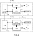
- Fig. 3 is a block diagram showing the system configuration of the reproduction apparatus 10.
- the master reproduction apparatus 11 includes a Bluetooth module (BTM) 11a, a digital signal processor (DSP) 11b, a micro controller unit (MCU) 11c, and a light emitting device 16.
- the slave reproduction apparatus 12 basically has the same configuration as that of the master reproduction apparatus 11.
- the master reproduction apparatus 11 and the slave reproduction apparatus 12 have memories such as a random access memory (RAM) and a read only memory (ROM), which are not illustrated, in addition to these components.
- RAM random access memory
- ROM read only memory
- Programs or data required to realize the operations or functions of the MCUs 11c and 12c is stored in the ROM.
- the light emitting device 16 includes a plurality of light emitting elements L1, L2, F1, S1, and the like, a driver for driving these, and the like.
- the BTM 11a communicates with a BTM (not illustrated) of the computer 50 (refer to Fig. 1 ) or a BTM 12a of another reproduction apparatus 10 on the basis of the Bluetooth standard.
- the BTM 11a mainly performs communication of audio data and data relevant to light emission control.
- the BTMs 11a and 112a function as a "transmission unit” and/or a "reception unit”.
- the DSP 11b of the master reproduction apparatus 11 mainly has a function of analyzing the audio data transmitted from the BTM 11a to generate analysis data and outputting the generated analysis data to the MCU 11c.
- the DSP 11b performs frequency analysis, in particular, low frequency extraction processing as analysis processing.
- the DSP 11b has a function of outputting audio data to the speaker unit 14 through, for example, a DA converter (not illustrated).
- the MCU 11c of the master reproduction apparatus 11 acquires the analysis data from the DSP 11b, and generates illumination information on the basis of the analysis data.
- the MCU 11c mainly functions as a "generation unit". Specifically, the MCU 11c detects a beat on the basis of data of base components as analysis data.
- the DSP 11b and the MCU 11c may detect not only the beat but also a tempo, a rhythm, and a key.
- the MCU 11c can generate illumination information corresponding to the audio data by generating illumination information on the basis of the information, such as the beat.
- the illumination information is information in which the light emission mode is associated with each of the light emitting elements L1 to L4, F1, F2, S1, and S2 of the master reproduction apparatus 11.
- the MCU 11c has a function of causing the plurality of light emitting elements to emit light in a light emission mode based on the generated illumination information.
- the MCU 11c mainly functions as a "light emission control unit".
- the MCU 11c outputs the generated illumination information to the BTM 11a.
- a universal asynchronous receiver transmitter UART
- the MCU 11c includes a light emission control command generation unit (not illustrated) that generates a light emission control command for controlling light emission in synchronization with the slave reproduction apparatus 12.
- the MCU 11c transmits the generated light emission control command to the slave reproduction apparatus 12 through the BTM 11a. In this manner, synchronous light emission by the respective light emitting elements is realized between the master reproduction apparatus 11 and one or more slave reproduction apparatuses 12.
- the MCU 11c further generates a reproduction control command for reproducing the audio data in synchronization with the slave reproduction apparatus 12.
- the MCU 11c transmits the generated reproduction control command to the slave reproduction apparatus 12 through the BTM 11a. In this manner, synchronous reproduction of audio data is realized between the master reproduction apparatus 11 and one or more slave reproduction apparatuses 12.
- the MCU 11c can realize synchronous reproduction by a known method using means, such as a system clock, a counter, and frequency control.
- the MCU 11c can transmit data including the illumination information, the light emission control command, and the reproduction control command described above, which serves as a header portion, and audio data, which serves as a data portion, to the slave reproduction apparatus 12 in a packet format.
- the MCU 11c transmits the illumination information and/or the light emission control command to the slave reproduction apparatus 12 independently of the audio data.
- the MCU 11c transmits data to be synchronized with audio data in a state in which the data to be synchronized with audio data is included in the illumination information and/or the light emission control command.
- the BTM 12a of the slave reproduction apparatus 12 receives the illumination information, the light emission control command, the reproduction control command, and the audio data from the master reproduction apparatus 11.
- the MCU 12c (or the DSP 12b) outputs the audio data to the speaker unit 14 in synchronization with the master reproduction apparatus 11. Further, the MCU 12c controls light emission of its own light emitting element on the basis of the illumination information and the light emission control command.
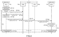
- Fig. 4 is a diagram showing a sequence of synchronization control of light emission by the master reproduction apparatus 11 and the slave reproduction apparatus 12.
- the MCU 11c of the master reproduction apparatus 11 generates a light emission control command (step 101).
- a timer for starting the execution of light emission control after XX msec is set by the system clock of the MCU 11c (step 102).
- the MCU 11c sends a request for the current time of the clock (BT clock) of the BTM 11a (step 103).
- the BTM clock transmits the current time of the BT clock to the MCU 11c in response to the request (step 104).
- the current time of the BT clock is set to, for example, "1000".
- the MCU 11c converts the light emission control execution time (start time) set in step 102 into a BT clock (step 105). For example, the BT clock after conversion is set to "1100".
- the MCU 11c transmits the generated light emission control command (execution time 1100) to the BTM 11a (step 106), and the BTM 11a transmits the light emission control command (execution time 1100) to the BTM 12a of the slave reproduction apparatus 12 (step 107).
- the BTM 12a of the slave reproduction apparatus 12 transmits the light emission control command to the MCU 12c (step 108). Then, the MCU 12c converts the light emission control execution time into a system clock, and sets the light emission control execution time after YY msec (step 109).
- the master reproduction apparatus 11 and the slave reproduction apparatus 12 are connected to each other by near field communication, the system clocks of the MCUs 11c and 12c are in synchronization with each other. Therefore, after step 109, the master reproduction apparatus 11 and the slave reproduction apparatus 12 can simultaneously execute light emission control at the time 1100 (steps 110a and 110b).
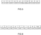
- Fig. 5 is a table showing illumination information according to Embodiment 1 generated by the master reproduction apparatus 11.
- the illumination information is information indicating the light emission mode associated with each of the light emitting elements as described above.
- color values are set in the light emitting elements (first light emitting elements) L1 to L4, S1, and S2 that can emit light in full color.
- Brightness values are set in the light emitting elements (second light emitting elements) F1 and F2 that can emit light in a single color.
- the color values and the brightness values are set by a predetermined algorithm on the basis of a beat detected by beat detection based on analysis data or a tempo, a rhythm, and a key detected on the basis of analysis data.
- the master reproduction apparatus 11 transmits the illumination information to the slave reproduction apparatus 12.
- the transmission interval is a predetermined time unit.
- the time unit is, for example, 30 msec to 200 msec.
- the slave reproduction apparatus 12 receives the illumination information. Then, the MCU 12c of the slave reproduction apparatus 12 assigns the illumination information to each corresponding light emitting element that the MCU 12c itself has, so that the light emitting element emits light. The slave reproduction apparatus 12 causes the light emitting element to emit light on the basis of the illumination information every time the illumination information is received, that is, for each time unit described above. Specifically, the slave reproduction apparatuses 12B and 12C of the second and third models execute light emission control as follows.
- the number, arrangement, and functional levels of light emitting elements of the slave reproduction apparatus 12A (refer to Part A of Fig. 2 ) of the first model are all the same as those of the master reproduction apparatus 11. Therefore, the slave reproduction apparatus 12A of the first model assigns the illumination information to its own light emitting element as it is, and controls the light emission in the same light emission mode as in the master reproduction apparatus 11. The same applies to Embodiment 2 to be described later.
- the number, arrangement, and functional levels of light emitting elements of the slave reproduction apparatus 12B (refer to Part C of Fig. 2 ) of the second model are different from those of the master reproduction apparatus 11.
- the light emitting elements L1 and L3 and the light emitting elements L1' and L3' of the master reproduction apparatus 11 are disposed differently, but the light emitting elements L1 and L3 are assigned to the light emitting elements L1' and L3', respectively. This assignment is determined in advance. That is, the light emitting element L1' corresponds to L1, and the light emitting element L3' corresponds to L3.
- the MCU 12c of the slave reproduction apparatus 12B generates illumination information by associating the data (color values) of the light emission modes of the light emitting elements L1 and L3 with L1' and L3'.
- the light emitting elements S1 and S2 of the master reproduction apparatus 11 are assigned to the light emitting elements S1' and S2', respectively.
- the arrangement of the light emitting elements S1 and S2 and the arrangement of the light emitting elements S1' and S2' are the same between these models, but the functional levels of S1' and S2' are single color and are different from the functional levels of S1 and S2.
- the MCU 12c of the slave reproduction apparatus 12B generates illumination information by converting the color values of S1 and S2 of the received illumination information into brightness values using a predetermined algorithm and associating the brightness values as light emission modes of the light emitting elements S1' and S2'.
- the illumination information is generated such that the light emission modes of the light emitting elements F1 and F2 of the master reproduction apparatus 11 are associated with the light emitting elements F1 and F2 of the slave reproduction apparatus 12B of the second model as they are. Since the slave reproduction apparatus 12B does not have light emitting elements corresponding to the light emitting elements L2 and L4 of the master reproduction apparatus 11, the light emission modes of the light emitting elements L2 and L4 are excluded or neglected.
- the MCU 12c of the slave reproduction apparatus 12B updates the illumination information as described above on the basis of the illumination information received from the master reproduction apparatus 11, and executes the light emission control of the light emitting element on the basis of this.
- the MCU 12c functions as a "light emission control unit”.
- the number, arrangement, and functional levels of light emitting elements of the slave reproduction apparatus 12C (refer to Part D of Fig. 2 ) of the third model are different from those of the master reproduction apparatus 11.
- the light emitting elements L1 and L3 and the light emitting elements L1" and L3" of the master reproduction apparatus 11 are disposed differently, but the light emitting elements L1 and L3 are assigned to the light emitting elements L1" and L3", respectively. This assignment is determined in advance. That is, the light emitting element L1" corresponds to L1, and the light emitting element L3" corresponds to L3.
- the MCU 12c of the slave reproduction apparatus 12 generates illumination information by associating the data (color values) of the light emission modes of the light emitting elements L1 and L3 with L1" and L3" as brightness values using the above-described Equation 1.
- the illumination information is generated such that the light emission modes of the light emitting elements F1 and F2 of the master reproduction apparatus 11 are associated with the light emitting elements F1 and F2 of the slave reproduction apparatus 12 of the third model as they are. Since the slave reproduction apparatus 12 does not have light emitting elements corresponding to the light emitting elements L2 and L4 of the master reproduction apparatus 11, the light emission modes of the light emitting elements L2 and L4 are excluded or neglected.
- the MCU 12c of the slave reproduction apparatus 12C updates the illumination information on the basis of the illumination information received from the master reproduction apparatus 11, and executes the light emission control of the light emitting element on the basis of this.
- the master reproduction apparatus 11 can control light emission individually for each of the light emitting elements on the basis of the illumination information. Further, the slave reproduction apparatus 12 can receive the illumination information and realize light emission according to audio data in synchronization with the master reproduction apparatus 11 on the basis of the illumination information or the updated illumination information.
- a plurality of users can share and enjoy music and light indoors and outdoors.
- Fig. 6 is a table showing illumination information according to Embodiment 2 generated by the master reproduction apparatus 11.
- the illumination information includes a pattern number (Pt. No), which defines a light emission pattern associated with each of the light emitting elements L1 to L4, F1, F2, S1, and S2, and a color table (Col-Tbl. No), which defines a color (Color).
- the light emission pattern is a light pattern defined in advance for each pattern number. There are several tens to several hundreds of light emission patterns, for example.
- the light emission pattern defines how to change the color using a color table in the illumination information on the basis of analysis data (information such as a beat based on the analysis data).
- the color table is a table showing the range of change in color defined in advance for each color table number. That is, one color table indicates data for changing colors in a range defined by a combination of a plurality of color values (RGB values).
- RGB values color values
- One color table defines the color range of the light emission pattern of each light emitting element in the illumination information. For example, one color table defines one or more basic colors and gradation colors or similar colors centered on the basic colors. For example, there are several to dozens of color tables.
- the transmission interval of the illumination information by the master reproduction apparatus 11 is a predetermined time unit.
- the time unit is a time for each timing at which at least one of data items of the light emission modes corresponding to light emitting elements and colors of the illumination information changes.
- the timing at which at least one of the data items of the light emission modes changes is, for example, a timing at which a beat, a tempo, a rhythm, a key, or the like changes or a timing at which the length of a pattern itself determined by the number of bars changes.
- the slave reproduction apparatus 12B of the second model receives the illumination information from the master reproduction apparatus 11. Then, the MCU 12c generates illumination information by assigning the light emission modes of the light emitting elements L1 and L3 of the master reproduction apparatus 11 as light emission modes of its own light emitting elements L1' and L3', thereby controlling the light emission.
- the light emission modes of the light emitting elements F1 and F2 of the master reproduction apparatus 11 are realized as they are by the light emitting elements F1 and F2 of the slave reproduction apparatus 12.
- the MCU 12c of the slave reproduction apparatus 12B of the second model generates illumination information by assigning the light emission modes of the light emitting elements S1 and S2 of the master reproduction apparatus 11 as light emission modes of its own light emitting elements S1' and S2', thereby controlling the light emission.
- the MCU 12c converts a plurality of color values in the color table into brightness values using the above-described Equation 1 to realize the light emission modes of the light emitting elements S1' and S2'.
- the slave reproduction apparatus 12C of the third model receives the illumination information from the master reproduction apparatus 11. Then, the MCU 12c generates illumination information by assigning the light emission modes of the light emitting elements L1 and L3 of the master reproduction apparatus 11 as light emission modes of its own light emitting elements L1" and L3", thereby controlling the light emission. In this case, the MCU 12c converts a plurality of color values in the color table into brightness values using the above-described Equation 1 to realize the light emission modes of the light emitting elements L1" and L3".
- the light emission modes of the light emitting elements F1 and F2 of the master reproduction apparatus 11 are realized as they are by the light emitting elements F1 and F2 of the slave reproduction apparatus 12C.
- the same effect as in the above Embodiment 1 can be obtained. Further, since the illumination information includes the light emission pattern and the color table, more various illuminations can be realized as compared with the above Embodiment 1.
- the reproduction system 100 includes a plurality of slave reproduction apparatuses 12A to 12C of three models. However, the reproduction system 100 may include one or more slave reproduction apparatuses 12 of at least one model.
- At least one of the slave reproduction apparatuses 12 may include only one light emitting element.
- the MCU 12c of each slave reproduction apparatus 12 can also control the light emission using the same illumination information in the flow of the light emitting element of the slave reproduction apparatus 12A, the light emitting element of the slave reproduction apparatus 12B, and the light emitting element of the slave reproduction apparatus 12C. That is, the light emission changes in such a manner that the delay effect is obtained in each slave reproduction apparatus 12. In this case, it is desirable to use the illumination information according to the above Embodiment 2.
- the master reproduction apparatus may determine the configuration or specifications of the slave reproduction apparatus when a connection is made by near field communication or other communication means. For example, at the time of the connection, the master reproduction apparatus may compare the number, arrangement, and functional levels of its own light emitting elements with those of the light emitting elements of the slave reproduction apparatus and transmit the comparison information to the slave reproduction apparatus. Therefore, since these reproduction apparatuses do not have to store in advance information of the number or the arrangement of light emitting elements of the other reproduction apparatus to be connected, it is possible to obtain the information at the time of the connection.
- the arrangement, number, and functional levels of the light emitting elements of each reproduction apparatus 10 can be appropriately changed in design.
- the functional levels of the light emitting elements of the master reproduction apparatus 11 are higher than those of the slave reproduction apparatuses 12B and 12C of the second and third models.
- the functional levels of the light emitting elements of the master reproduction apparatus 11 may be higher than those of the second and third models.
Landscapes
- Engineering & Computer Science (AREA)
- Multimedia (AREA)
- Physics & Mathematics (AREA)
- Acoustics & Sound (AREA)
- Signal Processing (AREA)
- Health & Medical Sciences (AREA)
- Audiology, Speech & Language Pathology (AREA)
- Computational Linguistics (AREA)
- Human Computer Interaction (AREA)
- General Health & Medical Sciences (AREA)
- Circuit Arrangement For Electric Light Sources In General (AREA)
- Reverberation, Karaoke And Other Acoustics (AREA)
Applications Claiming Priority (2)
| Application Number | Priority Date | Filing Date | Title |
|---|---|---|---|
| JP2017033490 | 2017-02-24 | ||
| PCT/JP2018/000777 WO2018154996A1 (fr) | 2017-02-24 | 2018-01-15 | Dispositif de reproduction maître, dispositif de reproduction esclave, et procédés d'émission de lumière associés |
Publications (3)
| Publication Number | Publication Date |
|---|---|
| EP3588972A1 true EP3588972A1 (fr) | 2020-01-01 |
| EP3588972A4 EP3588972A4 (fr) | 2020-02-12 |
| EP3588972B1 EP3588972B1 (fr) | 2024-07-17 |
Family
ID=63253232
Family Applications (1)
| Application Number | Title | Priority Date | Filing Date |
|---|---|---|---|
| EP18757002.3A Active EP3588972B1 (fr) | 2017-02-24 | 2018-01-15 | Dispositif de reproduction maître, dispositif de reproduction esclave, et procédés d'émission de lumière associés |
Country Status (5)
| Country | Link |
|---|---|
| US (1) | US11420134B2 (fr) |
| EP (1) | EP3588972B1 (fr) |
| JP (1) | JP6992798B2 (fr) |
| CN (1) | CN110100450B (fr) |
| WO (1) | WO2018154996A1 (fr) |
Families Citing this family (3)
| Publication number | Priority date | Publication date | Assignee | Title |
|---|---|---|---|---|
| EP3588972B1 (fr) * | 2017-02-24 | 2024-07-17 | Sony Group Corporation | Dispositif de reproduction maître, dispositif de reproduction esclave, et procédés d'émission de lumière associés |
| US10805664B2 (en) * | 2018-10-15 | 2020-10-13 | Bose Corporation | Wireless audio synchronization |
| WO2020220181A1 (fr) * | 2019-04-29 | 2020-11-05 | Harman International Industries, Incorporated | Haut-parleur présentant un mode de diffusion et procédé de diffusion associé |
Family Cites Families (44)
| Publication number | Priority date | Publication date | Assignee | Title |
|---|---|---|---|---|
| US4185276A (en) * | 1977-09-29 | 1980-01-22 | Benson Robert G | Sound and light display |
| US5769527A (en) * | 1986-07-17 | 1998-06-23 | Vari-Lite, Inc. | Computer controlled lighting system with distributed control resources |
| US5329431A (en) * | 1986-07-17 | 1994-07-12 | Vari-Lite, Inc. | Computer controlled lighting system with modular control resources |
| US6016038A (en) * | 1997-08-26 | 2000-01-18 | Color Kinetics, Inc. | Multicolored LED lighting method and apparatus |
| US7139617B1 (en) * | 1999-07-14 | 2006-11-21 | Color Kinetics Incorporated | Systems and methods for authoring lighting sequences |
| US20040052076A1 (en) * | 1997-08-26 | 2004-03-18 | Mueller George G. | Controlled lighting methods and apparatus |
| US6211626B1 (en) * | 1997-08-26 | 2001-04-03 | Color Kinetics, Incorporated | Illumination components |
| US6813777B1 (en) * | 1998-05-26 | 2004-11-02 | Rockwell Collins | Transaction dispatcher for a passenger entertainment system, method and article of manufacture |
| ATE539593T1 (de) * | 2000-06-21 | 2012-01-15 | Philips Solid State Lighting | Verfahren und vorrichtung zum steuern eines beleuchtungssystems in abhängigkeit einer audioeingabe |
| US7227075B2 (en) * | 2004-08-06 | 2007-06-05 | Henry Chang | Lighting controller |
| JP4724504B2 (ja) * | 2005-09-08 | 2011-07-13 | パイオニア株式会社 | 照明装置 |
| US7459623B2 (en) * | 2006-03-09 | 2008-12-02 | Robertson Bruce E | Sound responsive light system |
| US7924174B1 (en) * | 2006-05-26 | 2011-04-12 | Cooper Technologies Company | System for controlling a lighting level of a lamp in a multi-zone environment |
| JP5098036B2 (ja) | 2006-12-07 | 2012-12-12 | 株式会社メガチップス | 音声再生システム |
| JP5168632B2 (ja) * | 2008-03-13 | 2013-03-21 | オーデリック株式会社 | スピーカ配設システム及びスピーカ装置 |
| US10539311B2 (en) * | 2008-04-14 | 2020-01-21 | Digital Lumens Incorporated | Sensor-based lighting methods, apparatus, and systems |
| CN101662691A (zh) | 2008-08-28 | 2010-03-03 | 阿尔派株式会社 | 再现系统和再现方法 |
| US8964298B2 (en) * | 2010-02-28 | 2015-02-24 | Microsoft Corporation | Video display modification based on sensor input for a see-through near-to-eye display |
| FR2973622B1 (fr) * | 2011-03-29 | 2014-02-14 | Awox | Dispositif de diffusion de sons |
| US20130002144A1 (en) * | 2011-06-03 | 2013-01-03 | Osram Sylvania Inc. | Multimode color tunable light source and daylighting system |
| US10030833B2 (en) * | 2011-06-03 | 2018-07-24 | Osram Sylvania Inc. | Multimode color tunable light source and daylighting system |
| US8779681B2 (en) * | 2011-06-03 | 2014-07-15 | Osram Sylvania Inc. | Multimode color tunable light source |
| CN103179475A (zh) * | 2011-12-22 | 2013-06-26 | 深圳市三诺电子有限公司 | 无线音箱及其无线音箱系统 |
| WO2013105169A1 (fr) * | 2012-01-10 | 2013-07-18 | ソニー株式会社 | Dispositif à source lumineuse de type ampoule |
| US20130279706A1 (en) * | 2012-04-23 | 2013-10-24 | Stefan J. Marti | Controlling individual audio output devices based on detected inputs |
| US9572226B2 (en) * | 2012-07-01 | 2017-02-14 | Cree, Inc. | Master/slave arrangement for lighting fixture modules |
| JP5966784B2 (ja) * | 2012-09-07 | 2016-08-10 | ソニー株式会社 | 照明装置およびプログラム |
| BR112015014835B1 (pt) * | 2012-12-28 | 2023-02-23 | Sony Corporation | Dispositivo de reprodução de som |
| WO2014107131A1 (fr) * | 2013-01-07 | 2014-07-10 | Teenage Engineering Ab | Agencement de haut-parleurs sans fil |
| US9288088B1 (en) * | 2013-02-22 | 2016-03-15 | Pi Variables, Inc. | Synchronizing the behavior of discrete digital devices |
| US9980351B2 (en) * | 2013-08-12 | 2018-05-22 | Abl Ip Holding Llc | Lighting element-centric network of networks |
| WO2015092984A1 (fr) | 2013-12-18 | 2015-06-25 | ソニー株式会社 | Dispositif de reproduction acoustique |
| CN103974512A (zh) * | 2014-05-05 | 2014-08-06 | 生迪光电科技股份有限公司 | 一种基于照明装置的无线音乐调光方法及其系统 |
| CA2954589A1 (fr) * | 2014-07-07 | 2016-01-14 | Patrizio PISANI | Systeme de communication audiovisuelle a distance entre deux ou plusieurs utilisateurs, lampe avec des lumieres presentant des caracteristiques lumineuses pouvant varier en fonction de sources d'informations externes, specifiquement de type audio, et procede de communication associe |
| US10045427B2 (en) * | 2014-09-29 | 2018-08-07 | Philips Lighting Holding B.V. | System and method of autonomous restore point creation and restoration for luminaire controllers |
| JP6635047B2 (ja) | 2014-12-26 | 2020-01-22 | ソニー株式会社 | 情報処理装置、情報処理方法、及びプログラム |
| US10502442B2 (en) * | 2015-04-03 | 2019-12-10 | Lucis Technologies Holdings Limited | Device control system |
| WO2018200685A2 (fr) * | 2017-04-27 | 2018-11-01 | Ecosense Lighting Inc. | Procédés et systèmes pour plate-forme automatisée de conception, d'exécution, de déploiement et d'exploitation pour des installations d'éclairage |
| US10049663B2 (en) * | 2016-06-08 | 2018-08-14 | Apple, Inc. | Intelligent automated assistant for media exploration |
| US10586535B2 (en) * | 2016-06-10 | 2020-03-10 | Apple Inc. | Intelligent digital assistant in a multi-tasking environment |
| IT201600086875A1 (it) * | 2016-08-24 | 2018-02-24 | Osram Gmbh | Procedimento per controllare sorgenti di illuminazione, sistema e prodotto informatico corrispondenti |
| JP7095597B2 (ja) | 2016-09-23 | 2022-07-05 | ソニーグループ株式会社 | 再生装置、再生方法、プログラム、及び再生システム |
| KR102729069B1 (ko) * | 2016-12-01 | 2024-11-13 | 삼성전자 주식회사 | 음성 신호를 입력 또는 출력하는 램프 장치 및 상기 램프 장치의 구동 방법 |
| EP3588972B1 (fr) * | 2017-02-24 | 2024-07-17 | Sony Group Corporation | Dispositif de reproduction maître, dispositif de reproduction esclave, et procédés d'émission de lumière associés |
-
2018
- 2018-01-15 EP EP18757002.3A patent/EP3588972B1/fr active Active
- 2018-01-15 JP JP2019501112A patent/JP6992798B2/ja active Active
- 2018-01-15 CN CN201880005263.8A patent/CN110100450B/zh active Active
- 2018-01-15 US US16/471,724 patent/US11420134B2/en active Active
- 2018-01-15 WO PCT/JP2018/000777 patent/WO2018154996A1/fr not_active Ceased
Also Published As
| Publication number | Publication date |
|---|---|
| EP3588972B1 (fr) | 2024-07-17 |
| US11420134B2 (en) | 2022-08-23 |
| JPWO2018154996A1 (ja) | 2019-12-12 |
| EP3588972A4 (fr) | 2020-02-12 |
| WO2018154996A1 (fr) | 2018-08-30 |
| JP6992798B2 (ja) | 2022-01-13 |
| CN110100450B (zh) | 2021-08-03 |
| US20190380190A1 (en) | 2019-12-12 |
| CN110100450A (zh) | 2019-08-06 |
Similar Documents
| Publication | Publication Date | Title |
|---|---|---|
| US12363491B2 (en) | Electronic device and music visualization method thereof | |
| CN109716783B (zh) | 再现装置、再现方法、程序以及再现系统 | |
| EP3588972B1 (fr) | Dispositif de reproduction maître, dispositif de reproduction esclave, et procédés d'émission de lumière associés | |
| US9661724B2 (en) | Light-emitting device, method of controlling light-emitting device, and program | |
| CN106376148A (zh) | 音频灯具的控制方法、系统及音频灯具 | |
| CN105120528B (zh) | 一种设备间进行配置性设置的方法、装置及系统 | |
| EP3928594B1 (fr) | Amélioration de la reconnaissance d'un utilisateur d'une scène lumineuse | |
| US11553577B2 (en) | System and method for achieving synchronized audio and image control of lighting | |
| US20220284664A1 (en) | Image Display System, Display Control Method, and Light Emission Control Method | |
| US6876847B2 (en) | Control of synchronous display of melody information and different information on mobile communication terminal | |
| KR101443327B1 (ko) | 실시간 렌더링 3d 오브젝트 인터렉티브 멀티비전 시스템 및 그의 실시간 렌더링 3d 오브젝트 처리방법 | |
| US9521729B2 (en) | Systems and methods for programming embedded devices using graphical user interface | |
| JP2022159356A (ja) | 環境制御システム | |
| US10588208B1 (en) | Coordination of multiple lighting displays | |
| CN114222412A (zh) | 基于音乐律动的智能灯泡控制方法、终端和系统 | |
| KR20190091990A (ko) | 반주기와 연결되는 악보영상출력장치 및 이를 이용한 악보영상출력방법 | |
| CN114286478A (zh) | 一种灯具控制方法及其相关设备 | |
| JP7249859B2 (ja) | カラオケシステム | |
| EP3009939A1 (fr) | Serveur de fourniture de données de sortie, dispositif et système de traitement d'informations, procédé de fourniture de données de sortie, procédé de traitement d'informations et structure de données des données de contenu | |
| JPWO2018008081A1 (ja) | 照明制御データ生成用楽曲選択装置、照明制御データ生成用楽曲選択方法、および照明制御データ生成用楽曲選択プログラム | |
| US9805036B2 (en) | Script-based multimedia presentation | |
| CN119383798B (zh) | 联控灯效配置方法及装置、设备、介质 | |
| KR20140115744A (ko) | 조명 장치를 무선으로 제어할 수 있는 무선 제어 신호 분배 장치 및 무선 제어 신호 분배 시스템 | |
| KR20150050623A (ko) | 조명 제어 장치 및 조명 제어 방법 | |
| CN115314587A (zh) | 一种电子设备的控制方法、控制装置和电子设备 |
Legal Events
| Date | Code | Title | Description |
|---|---|---|---|
| STAA | Information on the status of an ep patent application or granted ep patent |
Free format text: STATUS: THE INTERNATIONAL PUBLICATION HAS BEEN MADE |
|
| PUAI | Public reference made under article 153(3) epc to a published international application that has entered the european phase |
Free format text: ORIGINAL CODE: 0009012 |
|
| STAA | Information on the status of an ep patent application or granted ep patent |
Free format text: STATUS: REQUEST FOR EXAMINATION WAS MADE |
|
| 17P | Request for examination filed |
Effective date: 20190924 |
|
| AK | Designated contracting states |
Kind code of ref document: A1 Designated state(s): AL AT BE BG CH CY CZ DE DK EE ES FI FR GB GR HR HU IE IS IT LI LT LU LV MC MK MT NL NO PL PT RO RS SE SI SK SM TR |
|
| AX | Request for extension of the european patent |
Extension state: BA ME |
|
| REG | Reference to a national code |
Ref country code: DE Ref legal event code: R079 Free format text: PREVIOUS MAIN CLASS: H04R0001000000 Ipc: H04R0001020000 Ref country code: DE Ref legal event code: R079 Ref document number: 602018071866 Country of ref document: DE Free format text: PREVIOUS MAIN CLASS: H04R0001000000 Ipc: H04R0001020000 |
|
| A4 | Supplementary search report drawn up and despatched |
Effective date: 20200115 |
|
| RIC1 | Information provided on ipc code assigned before grant |
Ipc: H04R 1/02 20060101AFI20200109BHEP Ipc: A63J 17/00 20060101ALI20200109BHEP |
|
| DAV | Request for validation of the european patent (deleted) | ||
| DAX | Request for extension of the european patent (deleted) | ||
| STAA | Information on the status of an ep patent application or granted ep patent |
Free format text: STATUS: EXAMINATION IS IN PROGRESS |
|
| 17Q | First examination report despatched |
Effective date: 20201217 |
|
| RAP3 | Party data changed (applicant data changed or rights of an application transferred) |
Owner name: SONY GROUP CORPORATION |
|
| GRAP | Despatch of communication of intention to grant a patent |
Free format text: ORIGINAL CODE: EPIDOSNIGR1 |
|
| STAA | Information on the status of an ep patent application or granted ep patent |
Free format text: STATUS: GRANT OF PATENT IS INTENDED |
|
| INTG | Intention to grant announced |
Effective date: 20240222 |
|
| GRAS | Grant fee paid |
Free format text: ORIGINAL CODE: EPIDOSNIGR3 |
|
| GRAA | (expected) grant |
Free format text: ORIGINAL CODE: 0009210 |
|
| STAA | Information on the status of an ep patent application or granted ep patent |
Free format text: STATUS: THE PATENT HAS BEEN GRANTED |
|
| P01 | Opt-out of the competence of the unified patent court (upc) registered |
Effective date: 20240529 |
|
| AK | Designated contracting states |
Kind code of ref document: B1 Designated state(s): AL AT BE BG CH CY CZ DE DK EE ES FI FR GB GR HR HU IE IS IT LI LT LU LV MC MK MT NL NO PL PT RO RS SE SI SK SM TR |
|
| REG | Reference to a national code |
Ref country code: CH Ref legal event code: EP |
|
| REG | Reference to a national code |
Ref country code: DE Ref legal event code: R096 Ref document number: 602018071866 Country of ref document: DE |
|
| REG | Reference to a national code |
Ref country code: IE Ref legal event code: FG4D |
|
| REG | Reference to a national code |
Ref country code: LT Ref legal event code: MG9D |
|
| REG | Reference to a national code |
Ref country code: NL Ref legal event code: MP Effective date: 20240717 |
|
| PG25 | Lapsed in a contracting state [announced via postgrant information from national office to epo] |
Ref country code: PT Free format text: LAPSE BECAUSE OF FAILURE TO SUBMIT A TRANSLATION OF THE DESCRIPTION OR TO PAY THE FEE WITHIN THE PRESCRIBED TIME-LIMIT Effective date: 20241118 |
|
| REG | Reference to a national code |
Ref country code: AT Ref legal event code: MK05 Ref document number: 1705220 Country of ref document: AT Kind code of ref document: T Effective date: 20240717 |
|
| PG25 | Lapsed in a contracting state [announced via postgrant information from national office to epo] |
Ref country code: NL Free format text: LAPSE BECAUSE OF FAILURE TO SUBMIT A TRANSLATION OF THE DESCRIPTION OR TO PAY THE FEE WITHIN THE PRESCRIBED TIME-LIMIT Effective date: 20240717 |
|
| PG25 | Lapsed in a contracting state [announced via postgrant information from national office to epo] |
Ref country code: PT Free format text: LAPSE BECAUSE OF FAILURE TO SUBMIT A TRANSLATION OF THE DESCRIPTION OR TO PAY THE FEE WITHIN THE PRESCRIBED TIME-LIMIT Effective date: 20241118 Ref country code: NL Free format text: LAPSE BECAUSE OF FAILURE TO SUBMIT A TRANSLATION OF THE DESCRIPTION OR TO PAY THE FEE WITHIN THE PRESCRIBED TIME-LIMIT Effective date: 20240717 |
|
| PG25 | Lapsed in a contracting state [announced via postgrant information from national office to epo] |
Ref country code: NO Free format text: LAPSE BECAUSE OF FAILURE TO SUBMIT A TRANSLATION OF THE DESCRIPTION OR TO PAY THE FEE WITHIN THE PRESCRIBED TIME-LIMIT Effective date: 20241017 |
|
| PG25 | Lapsed in a contracting state [announced via postgrant information from national office to epo] |
Ref country code: GR Free format text: LAPSE BECAUSE OF FAILURE TO SUBMIT A TRANSLATION OF THE DESCRIPTION OR TO PAY THE FEE WITHIN THE PRESCRIBED TIME-LIMIT Effective date: 20241018 Ref country code: FI Free format text: LAPSE BECAUSE OF FAILURE TO SUBMIT A TRANSLATION OF THE DESCRIPTION OR TO PAY THE FEE WITHIN THE PRESCRIBED TIME-LIMIT Effective date: 20240717 Ref country code: PL Free format text: LAPSE BECAUSE OF FAILURE TO SUBMIT A TRANSLATION OF THE DESCRIPTION OR TO PAY THE FEE WITHIN THE PRESCRIBED TIME-LIMIT Effective date: 20240717 |
|
| PG25 | Lapsed in a contracting state [announced via postgrant information from national office to epo] |
Ref country code: BG Free format text: LAPSE BECAUSE OF FAILURE TO SUBMIT A TRANSLATION OF THE DESCRIPTION OR TO PAY THE FEE WITHIN THE PRESCRIBED TIME-LIMIT Effective date: 20240717 |
|
| PG25 | Lapsed in a contracting state [announced via postgrant information from national office to epo] |
Ref country code: LV Free format text: LAPSE BECAUSE OF FAILURE TO SUBMIT A TRANSLATION OF THE DESCRIPTION OR TO PAY THE FEE WITHIN THE PRESCRIBED TIME-LIMIT Effective date: 20240717 |
|
| PG25 | Lapsed in a contracting state [announced via postgrant information from national office to epo] |
Ref country code: IS Free format text: LAPSE BECAUSE OF FAILURE TO SUBMIT A TRANSLATION OF THE DESCRIPTION OR TO PAY THE FEE WITHIN THE PRESCRIBED TIME-LIMIT Effective date: 20241117 Ref country code: AT Free format text: LAPSE BECAUSE OF FAILURE TO SUBMIT A TRANSLATION OF THE DESCRIPTION OR TO PAY THE FEE WITHIN THE PRESCRIBED TIME-LIMIT Effective date: 20240717 |
|
| PG25 | Lapsed in a contracting state [announced via postgrant information from national office to epo] |
Ref country code: HR Free format text: LAPSE BECAUSE OF FAILURE TO SUBMIT A TRANSLATION OF THE DESCRIPTION OR TO PAY THE FEE WITHIN THE PRESCRIBED TIME-LIMIT Effective date: 20240717 |
|
| PG25 | Lapsed in a contracting state [announced via postgrant information from national office to epo] |
Ref country code: RS Free format text: LAPSE BECAUSE OF FAILURE TO SUBMIT A TRANSLATION OF THE DESCRIPTION OR TO PAY THE FEE WITHIN THE PRESCRIBED TIME-LIMIT Effective date: 20241017 Ref country code: ES Free format text: LAPSE BECAUSE OF FAILURE TO SUBMIT A TRANSLATION OF THE DESCRIPTION OR TO PAY THE FEE WITHIN THE PRESCRIBED TIME-LIMIT Effective date: 20240717 |
|
| PG25 | Lapsed in a contracting state [announced via postgrant information from national office to epo] |
Ref country code: RS Free format text: LAPSE BECAUSE OF FAILURE TO SUBMIT A TRANSLATION OF THE DESCRIPTION OR TO PAY THE FEE WITHIN THE PRESCRIBED TIME-LIMIT Effective date: 20241017 Ref country code: PL Free format text: LAPSE BECAUSE OF FAILURE TO SUBMIT A TRANSLATION OF THE DESCRIPTION OR TO PAY THE FEE WITHIN THE PRESCRIBED TIME-LIMIT Effective date: 20240717 Ref country code: NO Free format text: LAPSE BECAUSE OF FAILURE TO SUBMIT A TRANSLATION OF THE DESCRIPTION OR TO PAY THE FEE WITHIN THE PRESCRIBED TIME-LIMIT Effective date: 20241017 Ref country code: LV Free format text: LAPSE BECAUSE OF FAILURE TO SUBMIT A TRANSLATION OF THE DESCRIPTION OR TO PAY THE FEE WITHIN THE PRESCRIBED TIME-LIMIT Effective date: 20240717 Ref country code: IS Free format text: LAPSE BECAUSE OF FAILURE TO SUBMIT A TRANSLATION OF THE DESCRIPTION OR TO PAY THE FEE WITHIN THE PRESCRIBED TIME-LIMIT Effective date: 20241117 Ref country code: HR Free format text: LAPSE BECAUSE OF FAILURE TO SUBMIT A TRANSLATION OF THE DESCRIPTION OR TO PAY THE FEE WITHIN THE PRESCRIBED TIME-LIMIT Effective date: 20240717 Ref country code: GR Free format text: LAPSE BECAUSE OF FAILURE TO SUBMIT A TRANSLATION OF THE DESCRIPTION OR TO PAY THE FEE WITHIN THE PRESCRIBED TIME-LIMIT Effective date: 20241018 Ref country code: FI Free format text: LAPSE BECAUSE OF FAILURE TO SUBMIT A TRANSLATION OF THE DESCRIPTION OR TO PAY THE FEE WITHIN THE PRESCRIBED TIME-LIMIT Effective date: 20240717 Ref country code: ES Free format text: LAPSE BECAUSE OF FAILURE TO SUBMIT A TRANSLATION OF THE DESCRIPTION OR TO PAY THE FEE WITHIN THE PRESCRIBED TIME-LIMIT Effective date: 20240717 Ref country code: BG Free format text: LAPSE BECAUSE OF FAILURE TO SUBMIT A TRANSLATION OF THE DESCRIPTION OR TO PAY THE FEE WITHIN THE PRESCRIBED TIME-LIMIT Effective date: 20240717 Ref country code: AT Free format text: LAPSE BECAUSE OF FAILURE TO SUBMIT A TRANSLATION OF THE DESCRIPTION OR TO PAY THE FEE WITHIN THE PRESCRIBED TIME-LIMIT Effective date: 20240717 |
|
| PG25 | Lapsed in a contracting state [announced via postgrant information from national office to epo] |
Ref country code: SM Free format text: LAPSE BECAUSE OF FAILURE TO SUBMIT A TRANSLATION OF THE DESCRIPTION OR TO PAY THE FEE WITHIN THE PRESCRIBED TIME-LIMIT Effective date: 20240717 Ref country code: RO Free format text: LAPSE BECAUSE OF FAILURE TO SUBMIT A TRANSLATION OF THE DESCRIPTION OR TO PAY THE FEE WITHIN THE PRESCRIBED TIME-LIMIT Effective date: 20240717 Ref country code: DK Free format text: LAPSE BECAUSE OF FAILURE TO SUBMIT A TRANSLATION OF THE DESCRIPTION OR TO PAY THE FEE WITHIN THE PRESCRIBED TIME-LIMIT Effective date: 20240717 |
|
| REG | Reference to a national code |
Ref country code: DE Ref legal event code: R097 Ref document number: 602018071866 Country of ref document: DE |
|
| PG25 | Lapsed in a contracting state [announced via postgrant information from national office to epo] |
Ref country code: EE Free format text: LAPSE BECAUSE OF FAILURE TO SUBMIT A TRANSLATION OF THE DESCRIPTION OR TO PAY THE FEE WITHIN THE PRESCRIBED TIME-LIMIT Effective date: 20240717 |
|
| PG25 | Lapsed in a contracting state [announced via postgrant information from national office to epo] |
Ref country code: CZ Free format text: LAPSE BECAUSE OF FAILURE TO SUBMIT A TRANSLATION OF THE DESCRIPTION OR TO PAY THE FEE WITHIN THE PRESCRIBED TIME-LIMIT Effective date: 20240717 |
|
| PG25 | Lapsed in a contracting state [announced via postgrant information from national office to epo] |
Ref country code: SK Free format text: LAPSE BECAUSE OF FAILURE TO SUBMIT A TRANSLATION OF THE DESCRIPTION OR TO PAY THE FEE WITHIN THE PRESCRIBED TIME-LIMIT Effective date: 20240717 |
|
| PLBE | No opposition filed within time limit |
Free format text: ORIGINAL CODE: 0009261 |
|
| STAA | Information on the status of an ep patent application or granted ep patent |
Free format text: STATUS: NO OPPOSITION FILED WITHIN TIME LIMIT |
|
| 26N | No opposition filed |
Effective date: 20250422 |
|
| REG | Reference to a national code |
Ref country code: DE Ref legal event code: R119 Ref document number: 602018071866 Country of ref document: DE |
|
| REG | Reference to a national code |
Ref country code: CH Ref legal event code: PL |
|
| PG25 | Lapsed in a contracting state [announced via postgrant information from national office to epo] |
Ref country code: SE Free format text: LAPSE BECAUSE OF FAILURE TO SUBMIT A TRANSLATION OF THE DESCRIPTION OR TO PAY THE FEE WITHIN THE PRESCRIBED TIME-LIMIT Effective date: 20240717 |
|
| PG25 | Lapsed in a contracting state [announced via postgrant information from national office to epo] |
Ref country code: LU Free format text: LAPSE BECAUSE OF NON-PAYMENT OF DUE FEES Effective date: 20250115 Ref country code: MC Free format text: LAPSE BECAUSE OF FAILURE TO SUBMIT A TRANSLATION OF THE DESCRIPTION OR TO PAY THE FEE WITHIN THE PRESCRIBED TIME-LIMIT Effective date: 20240717 |
|
| GBPC | Gb: european patent ceased through non-payment of renewal fee |
Effective date: 20250115 |
|
| PG25 | Lapsed in a contracting state [announced via postgrant information from national office to epo] |
Ref country code: DE Free format text: LAPSE BECAUSE OF NON-PAYMENT OF DUE FEES Effective date: 20250801 |
|
| PG25 | Lapsed in a contracting state [announced via postgrant information from national office to epo] |
Ref country code: GB Free format text: LAPSE BECAUSE OF NON-PAYMENT OF DUE FEES Effective date: 20250115 Ref country code: BE Free format text: LAPSE BECAUSE OF NON-PAYMENT OF DUE FEES Effective date: 20250131 |
|
| PG25 | Lapsed in a contracting state [announced via postgrant information from national office to epo] |
Ref country code: FR Free format text: LAPSE BECAUSE OF NON-PAYMENT OF DUE FEES Effective date: 20250131 |
|
| PG25 | Lapsed in a contracting state [announced via postgrant information from national office to epo] |
Ref country code: CH Free format text: LAPSE BECAUSE OF NON-PAYMENT OF DUE FEES Effective date: 20250131 |
|
| REG | Reference to a national code |
Ref country code: BE Ref legal event code: MM Effective date: 20250131 |
|
| PG25 | Lapsed in a contracting state [announced via postgrant information from national office to epo] |
Ref country code: IE Free format text: LAPSE BECAUSE OF NON-PAYMENT OF DUE FEES Effective date: 20250115 |
|
| PG25 | Lapsed in a contracting state [announced via postgrant information from national office to epo] |
Ref country code: IT Free format text: LAPSE BECAUSE OF FAILURE TO SUBMIT A TRANSLATION OF THE DESCRIPTION OR TO PAY THE FEE WITHIN THE PRESCRIBED TIME-LIMIT Effective date: 20240717 |