EP3589097B1 - Multikonfigurationsressourcenmodulschacht - Google Patents
Multikonfigurationsressourcenmodulschacht Download PDFInfo
- Publication number
- EP3589097B1 EP3589097B1 EP19183075.1A EP19183075A EP3589097B1 EP 3589097 B1 EP3589097 B1 EP 3589097B1 EP 19183075 A EP19183075 A EP 19183075A EP 3589097 B1 EP3589097 B1 EP 3589097B1
- Authority
- EP
- European Patent Office
- Prior art keywords
- bay
- adaptor
- configuration
- common
- resource modules
- Prior art date
- Legal status (The legal status is an assumption and is not a legal conclusion. Google has not performed a legal analysis and makes no representation as to the accuracy of the status listed.)
- Active
Links
Images




Classifications
-
- G—PHYSICS
- G06—COMPUTING OR CALCULATING; COUNTING
- G06F—ELECTRIC DIGITAL DATA PROCESSING
- G06F1/00—Details not covered by groups G06F3/00 - G06F13/00 and G06F21/00
- G06F1/16—Constructional details or arrangements
- G06F1/18—Packaging or power distribution
- G06F1/181—Enclosures
-
- H—ELECTRICITY
- H05—ELECTRIC TECHNIQUES NOT OTHERWISE PROVIDED FOR
- H05K—PRINTED CIRCUITS; CASINGS OR CONSTRUCTIONAL DETAILS OF ELECTRIC APPARATUS; MANUFACTURE OF ASSEMBLAGES OF ELECTRICAL COMPONENTS
- H05K7/00—Constructional details common to different types of electric apparatus
- H05K7/14—Mounting supporting structure in casing or on frame or rack
- H05K7/1485—Servers; Data center rooms, e.g. 19-inch computer racks
- H05K7/1488—Cabinets therefor, e.g. chassis or racks or mechanical interfaces between blades and support structures
- H05K7/1489—Cabinets therefor, e.g. chassis or racks or mechanical interfaces between blades and support structures characterized by the mounting of blades therein, e.g. brackets, rails, trays
-
- A—HUMAN NECESSITIES
- A47—FURNITURE; DOMESTIC ARTICLES OR APPLIANCES; COFFEE MILLS; SPICE MILLS; SUCTION CLEANERS IN GENERAL
- A47B—TABLES; DESKS; OFFICE FURNITURE; CABINETS; DRAWERS; GENERAL DETAILS OF FURNITURE
- A47B81/00—Cabinets or racks specially adapted for other particular purposes, e.g. for storing guns or skis
-
- H—ELECTRICITY
- H05—ELECTRIC TECHNIQUES NOT OTHERWISE PROVIDED FOR
- H05K—PRINTED CIRCUITS; CASINGS OR CONSTRUCTIONAL DETAILS OF ELECTRIC APPARATUS; MANUFACTURE OF ASSEMBLAGES OF ELECTRICAL COMPONENTS
- H05K7/00—Constructional details common to different types of electric apparatus
- H05K7/14—Mounting supporting structure in casing or on frame or rack
- H05K7/1422—Printed circuit boards receptacles, e.g. stacked structures, electronic circuit modules or box like frames
- H05K7/1424—Card cages
-
- H—ELECTRICITY
- H05—ELECTRIC TECHNIQUES NOT OTHERWISE PROVIDED FOR
- H05K—PRINTED CIRCUITS; CASINGS OR CONSTRUCTIONAL DETAILS OF ELECTRIC APPARATUS; MANUFACTURE OF ASSEMBLAGES OF ELECTRICAL COMPONENTS
- H05K7/00—Constructional details common to different types of electric apparatus
- H05K7/14—Mounting supporting structure in casing or on frame or rack
- H05K7/1422—Printed circuit boards receptacles, e.g. stacked structures, electronic circuit modules or box like frames
- H05K7/1424—Card cages
- H05K7/1425—Card cages of standardised dimensions, e.g. 19"-subrack
-
- H—ELECTRICITY
- H05—ELECTRIC TECHNIQUES NOT OTHERWISE PROVIDED FOR
- H05K—PRINTED CIRCUITS; CASINGS OR CONSTRUCTIONAL DETAILS OF ELECTRIC APPARATUS; MANUFACTURE OF ASSEMBLAGES OF ELECTRICAL COMPONENTS
- H05K7/00—Constructional details common to different types of electric apparatus
- H05K7/14—Mounting supporting structure in casing or on frame or rack
- H05K7/1485—Servers; Data center rooms, e.g. 19-inch computer racks
- H05K7/1488—Cabinets therefor, e.g. chassis or racks or mechanical interfaces between blades and support structures
-
- A—HUMAN NECESSITIES
- A47—FURNITURE; DOMESTIC ARTICLES OR APPLIANCES; COFFEE MILLS; SPICE MILLS; SUCTION CLEANERS IN GENERAL
- A47B—TABLES; DESKS; OFFICE FURNITURE; CABINETS; DRAWERS; GENERAL DETAILS OF FURNITURE
- A47B57/00—Cabinets, racks or shelf units, characterised by features for adjusting shelves or partitions
- A47B57/06—Cabinets, racks or shelf units, characterised by features for adjusting shelves or partitions with means for adjusting the height of the shelves
- A47B57/08—Cabinets, racks or shelf units, characterised by features for adjusting shelves or partitions with means for adjusting the height of the shelves consisting of grooved or notched ledges, uprights or side walls
-
- A—HUMAN NECESSITIES
- A47—FURNITURE; DOMESTIC ARTICLES OR APPLIANCES; COFFEE MILLS; SPICE MILLS; SUCTION CLEANERS IN GENERAL
- A47B—TABLES; DESKS; OFFICE FURNITURE; CABINETS; DRAWERS; GENERAL DETAILS OF FURNITURE
- A47B57/00—Cabinets, racks or shelf units, characterised by features for adjusting shelves or partitions
- A47B57/06—Cabinets, racks or shelf units, characterised by features for adjusting shelves or partitions with means for adjusting the height of the shelves
- A47B57/08—Cabinets, racks or shelf units, characterised by features for adjusting shelves or partitions with means for adjusting the height of the shelves consisting of grooved or notched ledges, uprights or side walls
- A47B57/10—Cabinets, racks or shelf units, characterised by features for adjusting shelves or partitions with means for adjusting the height of the shelves consisting of grooved or notched ledges, uprights or side walls the grooved or notched parts being the side walls or uprights themselves
-
- A—HUMAN NECESSITIES
- A47—FURNITURE; DOMESTIC ARTICLES OR APPLIANCES; COFFEE MILLS; SPICE MILLS; SUCTION CLEANERS IN GENERAL
- A47B—TABLES; DESKS; OFFICE FURNITURE; CABINETS; DRAWERS; GENERAL DETAILS OF FURNITURE
- A47B57/00—Cabinets, racks or shelf units, characterised by features for adjusting shelves or partitions
- A47B57/58—Cabinets, racks or shelf units, characterised by features for adjusting shelves or partitions with means for adjusting partitions horizontally
-
- H—ELECTRICITY
- H01—ELECTRIC ELEMENTS
- H01R—ELECTRICALLY-CONDUCTIVE CONNECTIONS; STRUCTURAL ASSOCIATIONS OF A PLURALITY OF MUTUALLY-INSULATED ELECTRICAL CONNECTING ELEMENTS; COUPLING DEVICES; CURRENT COLLECTORS
- H01R13/00—Details of coupling devices of the kinds covered by groups H01R12/70 or H01R24/00 - H01R33/00
- H01R13/46—Bases; Cases
- H01R13/516—Means for holding or embracing insulating body, e.g. casing, hoods
- H01R13/518—Means for holding or embracing insulating body, e.g. casing, hoods for holding or embracing several coupling parts, e.g. frames
Definitions
- Computing systems such as servers, storage arrays, converged systems, composable systems, etc.-may include processing units that utilize various resources, such as memory, storage devices, accelerators, and the like.
- the resources may be provided as resource modules which are modular self-contained packages having standardized form-factors and which are physically separate from the processing units.
- the resource modules may be connected indirectly to the processing units, for example via cabling, a midplane, network devices, or the like.
- US 2014/084764 A1 discloses a locking mechanism for an adaptor assembly of a server rack chassis.
- the server rack chassis includes bays for receiving servers, and an adaptor assembly.
- the adaptor assembly includes an enclosure, a guide rail, a plate, and rails.
- the plate is mounted within the middle of the enclosure to provide structural support to the enclosure, and the rails are mounted on the inside of the walls to provide alignment and support of servers within the enclosure.
- the adaptor assembly can be designed to receive multiple servers.
- DE 2936499 A1 discloses housing for printed circuit boards, wherein the circuit housing is basically a rectangle and has guide ribs arranged in pairs at the side walls, between which, in a vertical direction to the base, circuit boards can be slotted in and held firmly. The housing is able to accept circuit boards of various dimensions.
- US 2015/173235 A1 discloses a divider for a bay of a blade server chassis that includes a plurality of posts, a plurality of flex tabs, and a rail. The posts are located along a first side of the divider, and are configured to be inserted within respective holes in a first panel of the bay of the blade server chassis. In accordance with the invention, there is provided a multi-configuration bay according to claim 1.
- Multiple resource modules may be housed in an enclosure that may be referred to as a bay, which itself may be housed within a chassis of a computing system.
- the bay may include engagement features that hold the resource modules in installed positions and provide physical support for the resource modules.
- the bay may also hold communications connectors (e.g., electrical and/or optical connectors) in locations aligned with the installation positions, such that a resource module installed in the bay can be electrically and/or optically connected (e.g., via cables) to the main board(s) of the computing system.
- the bay may provide electromagnetic interference (EMI) shielding for the resource modules housed therein.
- EMI electromagnetic interference
- manufacturers may desire to offer multiple distinct configurations for their computing systems, so that they can better serve varied needs of customers.
- manufacturers may desire to offer a family of computing systems that all have a similar architecture as one another but that have multiple different resource module configurations.
- one configuration may include just storage resource modules
- another configuration may include a mix of storage resource modules and memory resource modules
- another configuration may include accelerators, and so on.
- some configurations may include vertically oriented resource modules
- some configurations may include horizontally oriented resource modules
- some configurations may include both vertically and horizontally oriented resource modules
- some configurations may include different form factors of resource modules (e.g., modules with different widths or heights).
- the manufacturer may need to design different types of bays to house the different combinations of resource modules. For example, a configuration that has storage resource modules vertically oriented may require a first type of bay, while a configuration that has accelerator resource modules oriented horizontally may require a second type of bay.
- SKU stock-keeping-unit
- an example multi-configuration bay is disclosed herein that can alleviate the above-noted concerns, among others.
- the multi-configuration bay is capable of being configured into multiple different configurations.
- the multi-configuration bay is capable of being placed in configurations in which the bay holds resource modules vertically ("vertical configurations") and configurations in which the bay holds resource modules horizontally ("horizontal configurations").
- the multi-configuration bay may be capable of being placed in multiple configurations that accommodate different sizes and combinations of resource modules.
- a single bay may be used to construct a variety of different resource module configurations, thereby avoiding the costs and SKU proliferation mentioned above that would otherwise occur if unique bays were designed for each such configuration.
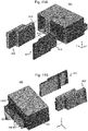
- the multi-configuration bay may include a common bay (see Fig. 2 ) and an adaptor (see Fig. 3 ) that is designed to be inserted into the common bay, and the configuration of the configurable bay may be changed by inserting or removing the adaptor from the common bay.
- the multi-configuration bay may be configured to a horizontal configuration by inserting the adaptor in the common bay (see Fig. 1 ), and the multi-configuration bay may be configured to a vertical configuration by removing the adaptor from the common bay (see Fig 11 ).
- the adaptor may include rails that are on vertical side walls of the adaptor and that are designed to hold horizontally oriented resource modules, and therefore when the adaptor is installed in the common bay the rails of the adaptor may hold resource modules in horizontally oriented installed positions.
- the common bay may include rails that are on horizontal top and bottom walls of the common bay and that are designed to hold vertically oriented resource modules, and therefore when the adaptor is removed from the common bay the rails of the common bay may hold resource modules in vertically oriented installed positions.
- the multi-configuration bay may include one or more vertical dividers that are designed to be installed vertically between side walls of the common bay when the adaptor is installed therein.
- the vertical dividers may include rails designed to hold horizontally oriented resource modules. Different horizontal configurations of the multi-configuration bay may be obtained based on how many of the vertical dividers are used and where they are installed. These different horizontal configurations may accommodate resource modules with different widths.
- the multi-configuration bay may, in some examples, allow a computing device to be reconfigured post manufacture.
- a computing device initially configured to house resource modules horizontally could be reconfigured to house resource modules vertically by removing the adaptor, or vice-versa.
- the form factors (e.g., widths) of resource modules that can be included in the bay may be changed by inserting or removing vertical dividers.
- this reconfiguration may be accomplished without needing specialized tools and/or without needing to disassemble the chassis.
- the reconfiguration may be done without needing to buy, produce, or obtain any extra parts (e.g., reconfiguring the bay by simply removing the adaptor or the vertical divider).
- Fig. 1 illustrates, in exploded perspective view, an example multi-configuration bay 10, together with example resource modules 600 housed in the multi-configuration bay 10.
- the multi-configuration bay 10 includes a common bay 100 (see also Figs. 2 and 5 ), an adaptor 200 that is installable within the common bay 100 (see also Figs. 3 and 5 ), a vertical divider 300 that is installable in the common bay between the side walls 201R/L of the adaptor (see also Figs. 4-5 ), and a midplane 400 connected to a rear of the common bay 100 (see also Fig. 6 ).
- the common bay 10 is configured to hold computer resource modules 600 in vertically oriented installed-positions when the adaptor 200 is not installed in the common bay 100 (see Fig.
- the adaptor 200 is configured to hold computer resource modules 600 in horizontally oriented installed positions when it is installed in the common bay 100 (see Fig. 1 ).
- the vertical divider 300 is configured to hold, in conjunction with the adaptor 200, resource modules 600 in horizontally oriented installed position when the adaptor 200 and the vertical divider 300 are installed in the common bay 100.
- Connectors 500 are also illustrated, which may be held by the midplane 400 so as to align with the installed positions of the resource modules 600.
- Figs. 2 and 5 illustrate the common bay 100 (occasionally referred to as "bay 100") in greater detail.
- the common bay may include four walls 101 connected to one another, and first rails 110 on interior facing sides of the top wall 101T and the bottom wall 101B (see Figs. 2 & 5 ).
- the first rails 110 are configured to hold the resource modules 600 in vertically oriented installed positions (see Figs. 2 , 5 , & 11 ).
- the first rails 110 define channels 111 between adjacent rails 110 (see Figs. 2 & 5 ), and the resource modules 600 may include engagement features 610 (see Figs. 1 and 11 ) that fit into the channels 111 as the resource modules 600 are slid into the bay 100 (see Fig. 11 ), such that the rails 110 passively guide the resource modules 600 to the installed position as they are slid towards a rear of the bay 100.
- the common bay 100 may also include slots 120 in side walls 101R/101L (see Fig. 2 ), which are part of a latch that is to secure the adaptor 200 to the common bay 100.
- the slots 120 may be configured to receive a tab 230 of the adaptor 200 (see Fig. 5 ).
- the rails 110 may be spaced such that the installed resource modules 600 are tightly packed within the bay 100.
- tightly packed means that the mean distance (e.g., air gap) between adjacent resource modules 600 ( ⁇ in Fig. 11A ), is less than 2 mm.
- one or more of the rails 110 may be configured as divider rails 110C, which are designed to accommodate a vertical divider 300.
- divider rails 110C are designed to accommodate a vertical divider 300.
- a divider rail 110C is illustrated, but in practice any number of divider rails 110C could be included.
- the divider rail 110C includes a groove 112 that is designed to receive a bottom or top end of the vertical divider 300, thereby helping to secure the vertical divider 300 when installed.
- the multi-configuration bay 10 may be designed to accommodate specific form factors of resource modules 600.
- the resource modules 600 may include at least a reference resource module 601 which has a reference form factor, and the common bay 100 may be dimensioned based on the reference form factor.
- a rail spacing d 1 for the first rails 110 may be set based on a height h of the reference resource modules 601, and a distance d 2 between opposing first rails may be set based on the width w of the reference resource modules 601, as described in greater detail below.
- depth refers to the dimension of the resource modules 600 that extends from front-to-back in the bay 10 when installed therein (which is aligned with the z-direction for the resource modules 600 illustrated in Fig. 1 ); "width” refers to the longest dimension of the module 600 excluding depth (which is aligned with x-direction for the resource modules 600 illustrated in Figs. 1 ); and “height” refers to the shortest dimension of the module 600 excluding depth (which is aligned with y-direction for the resource modules 600 illustrated in Fig. 1 ).
- the common bay 10 may be dimensioned such that the distance d 2 between opposite rails 110 (see Fig. 5 ), is large enough to allow the reference resource modules 601 to be installed in vertical orientation and small enough that the reference resource modules 601 are still held securely by the rails 110.
- w ⁇ d 2 ⁇ w + ⁇ where w is the width of the reference resource module 601 excluding its engagement features 610 and w+ ⁇ is the width of the reference resource module 601 including its engagement features 610.
- d 2 is between 70 and 80 mm-for example, in one implementation d 2 is 76 mm.
- the width of an interior chamber of the common bay 10 may be such that an integer number of reference resource modules 601 can be tightly packed in the common bay 10. For example, if the common bay 10 is to have a capacity to house k vertically oriented reference resource modules 601, then the width of the common bay 10 may be approximately k*d 1 . In addition, in some examples, the width of the interior chamber of the common bay 11 may be sufficiently wide to accommodate the adaptor 200 that has an interior dimension of d 4 , as illustrated in Fig. 5 and described below.
- the widths and heights of the rails 110 may be set based on the engagement features 610 of the reference resource modules 601, which may be for example, a flange, a roller, a rail, etc.
- the engagement features 610 of the resource modules 600 are x-mm in height
- the channels 111 may each be (x + ⁇ ) mm wide and the rails 110 may each be (d 1 - x - ⁇ ) mm wide, where ⁇ constitutes a small tolerance to allow sliding.
- the first rail 110A and the last rail 110B on each of the walls 101T/101B may be narrower than the other rails 110, to reduce any gap between a first or last resource module 600 and the side walls 102R/102L.
- the adaptor 200 includes vertical side walls 201R and 201L, which are connected to one another by a horizontal wall 201M, a top span 203T, and a bottom span 203B (see Figs. 3 & 5 ).
- the adaptor 200 may also include EMI tabs 240.
- the adaptor 200 also includes second rails 210 on interior sides of the side walls 201R/201L (see Figs. 3 & 5 ).
- the second rails 210 are configured to hold the resource modules 600 in horizontally oriented installed positions (see Figs. 1 , 3 , & 5 ).
- the second rails 210 define channels 211 between adjacent rails 210 (see Figs.
- the resource modules 600 may include engagement features 610 that fit into the channels 211 as the resource modules 600 are slid into the bay 100, such that the rails 210 passively guide the resource modules 600 to the installed position as they are slid towards a rear of the bay 100.
- the second rails 210 may be sized and spaced similarly to how the first rails 110 are sized and spaced.
- the spacing d 3 of the rails 210 may be equal to the spacing d 1 of the rails 110, which may be equal to a height h of the reference resource module 601 plus the inter-module gap ⁇ .
- First and last rails 210A/B on each side wall 201R/L may be narrower than the other rails 210 (see Figs. 3 & 5 ).
- the horizontal wall 201M may connect to the side walls 201R/L at a rail 210, as illustrated in Figs. 3 and 5 . In other examples (not illustrated), the horizontal wall 201M may connect to the side walls 201R/L in a channel 211.
- the horizontal wall 201M defines two spaces 250: one space 250A above the wall 201M and between the walls 201R and 201L, and another space 250B below the wall 201M and between the walls 201R and 201L (see Fig. 3 ).
- these spaces 250A/B are bounded by the walls 101T and 101B, respectively, and may also be referred to herein as "chambers".
- the horizontal wall 201M divides the interior of the common bay 100 into two chambers 250A and 250B.
- the width of each of the chambers 250A/B is d 4 (see Fig. 5 ), and therefore when no vertical dividers 300 are installed, each chamber 250A/B is capable of receiving/holding resource modules 600 that have a width (excluding engagement features 610) of d 4 .
- the adaptor 200 may be desired for the adaptor 200 to hold resource modules 600 that have widths that are less than d 4 .
- one or more vertical dividers 300 may be included in one or both chambers 250 of the adaptor 200 (see Fig. 4B ).
- An example vertical divider 300 is illustrated in Figs. 4-5 . When such a divider 300 is included in a chamber 250, it divides the chamber 250 into sub-chambers 251. Specifically, if n vertical dividers are included in a chamber 250, they divide the chamber 250 into n+1 sub-chambers 251. For example, as illustrated in Figs. 4B and 5 , if a single vertical divider 300 is installed in the chamber 250B, it forms two sub-chambers 251A and 251B.
- the second rails 210 of the adaptor 200 may cooperate with third rails 310 of the vertical divider 300 to hold resource modules 600 in horizontally oriented installed positions (see, e.g., Fig. 8A ).
- the vertical dividers 300 may enable resource modules 600 having widths that are smaller than d 4 to be installed in the sub-chambers 251.
- the vertical dividers 300 may be reversibly installable in and uninstallable from the adaptor 200.
- the adaptor 200 may include slots 220 (see Figs. 3 , 4B and 5 ), which are configured to receive and releasably hold tabs 320 of a vertical divider 300 when it is installed (see Fig. 4A-5 ).
- the top and bottom spans 203A/B may also include notches 221 that may releasably hold a front-bottom portion of the vertical divider 300 (see Figs. 2 and 4B ).
- One benefit of having the vertical dividers 300 be reversibly installable/uninstallable is that it increases the number of distinct configurations that can be created for a computing device using the same basic multi-configuration bay 10. Another benefit is that it may provide additional possibilities for changing the configuration of a computing device after its manufacture.
- the vertical divider 300 may be installed in the adaptor 200 by inserting the tabs 320 into the slots 220 and inserting the front-bottom portion of the vertical divider 300 in the notch 221 (see Fig. 4B ).
- the divider 300 may be installed in the adaptor 200 when it is outside of the common bay 100, and then the combined adaptor 200 and divider 300 assembly may be installed in the common bay 100 by inserting a rear portion of the adaptor 200/divider 300 assembly into the front side of the interior chamber of the bay 100 and then sliding the assembly rearwards.
- the bottom portion of the divider 300 may be received in the groove 112 as it is slid rearward in the common bay 100.
- the tabs 220, notches 221, and groove 112 may hold the divider 300 in its installed location (see Fig. 5 ).
- the reverse of the forgoing operations may be employed.
- one or more vertical dividers 300 may be permanently included in the adaptor 200.
- the vertical dividers 300 and adaptor 200 may be integrally formed as one piece, or may be permanently connected to one another (e.g., by welding, adhesive, etc.).
- the common bay 100 and adaptor 200 are configured to include two installation locations for vertical dividers 300, one in the chamber 250A and one in the chamber 250B.
- the common bay 100 illustrated in these examples includes two grooves 112, one in a top rail 110 and one in a bottom rail 110 (see Fig. 2 ), and the adaptor includes slots 220 corresponding to both of the grooves 112 (see Fig. 3 ).
- one vertical divider 300 may be installed in one groove 112 and another vertical divider 300 may be installed in the other groove 112, with both dividers 300 using the same set of slots 120 (i.e., one set of slots 120 can accommodate two dividers 300, one above and one below).
- any number of installation locations for vertical dividers 300 may be included.
- the installation locations for vertical dividers 300 in the chamber 250A do not necessarily need to align with installation locations for vertical dividers in the chamber 250B.
- three slots 120 are illustrated for the set of slots 120, in other examples any number of slots 120 may be included per set of slots 220.
- the multi-configuration bay 10 includes latches to secure the adaptor 200 to the bay 100 once it has been installed.
- the latch may include tabs 230, which are included as part of the adaptor 200, and slots 120, which are included in the walls 101R/L of the common bay 100 (see Figs. 2 , 3 , & 5 ).
- the adaptor 200 includes tabs 230 that extend through the side walls 201R/L (which may include extending through a rail 210 or through a channel 211) (see Figs. 2 and 5 ).
- the tabs 230 may be aligned with the slots 120 and configured to be slidable in a horizontal direction (i.e., along the x-axis in the figures), such that the tabs 230 can be slid into the slots 120 to secure the adaptor 200 to the bay 100 and slid out of the slot 120 to release the adaptor 200 from the bay 100 (see Figs. 2 and 5 ).
- the tabs 120 may include a first end 231 that engages with the slots 120 and is on an outward facing side of the wall 201R/L, and a second end 233 that can be actuated by a user and is on an inward facing side of the wall 201R/L (see Figs. 2 and 5 ).
- the second ends 233 of the tabs 230 may be located within openings 232 in the horizontal wall 201M (see Figs. 2 and 5 ).
- the top span 203T and the bottom span 203B may be configured such that, when the adaptor 200 is installed in the common bay 100, the spans 203T/B fit in spaces at a front of the common bay 100 that do not have first rails 110 in them.
- the top span 203T and the bottom span 203B may include EMI tabs 240, which are to contact installed resource modules 600 and facilitate EMI shielding (see Fig. 3 ).
- the top span 203T and the bottom span 203B may also aid in structural support for the adaptor 200. In some examples (not illustrated), the top span 203T and/or the bottom span 203B may be omitted.
- the horizontal wall 201M may be omitted.
- vertical dividers 300 may be included in the adaptor, and these vertical dividers 300 may have a height equal to the full height of the interior of the common bay 100.
- Figs. 1 and 5 Although an example is illustrated in Figs. 1 and 5 in which there is one vertical divider 300 in the lower chamber 250B and none in the upper chamber 250A, other arrangements could be included.
- the vertical divider 300 could be include in the upper chamber 250A but not in the lower chamber 250B, or a vertical divider 300 could be included in both chambers 250A/B, or no vertical dividers 300 could be included in the adaptor 200.
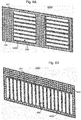
- Figs. 6A and 6B illustrate example midplanes of the multi-configuration bay 10.
- Fig. 6A illustrates a horizontal midplane 400H which is to be used in horizontal configurations of the multi-configuration bay 10.
- Fig. 6B illustrates a vertical midplane 400V which is to be used in vertical configurations of the multi-configuration bay 10.
- the midplanes 400H/V both include an outer frame 401, a mesh (e.g., lattice) 402 connected to the outer frame 401, and connector-frames 405 connected to the mesh 402 and defining apertures 406 in the mesh 402.
- the connector frames 405 may be configured to receive and hold communications connectors 500, such as electrical or optical cable connectors 500.
- the connector frames 405 may be to receive Gen-Z connectors 500.
- the connectors 500 may be pressed into the apertures 406 and then snap onto the connector frames 405.
- the mesh 402 may fill the entire area encircled by the outer frame 401, with the exception of the regions occupied by the connector-frames 405 and their apertures 406, and may support the connector-frames 405.
- the main difference between the horizontal and vertical midplanes 400H/V is the orientation and locations of their connector frames 405.
- the horizontal midplane 400H includes horizontally oriented connector frames 405H (i.e., the longer dimension thereof is horizontal), which are located so as to be aligned with horizontal installed positions in the bay 10.
- the vertical miplane 400V includes vertically oriented connector frames 405V (i.e., the longer dimension thereof is vertical), which are located so as to be aligned with vertical installed positions in the bay 10.
- the midplanes 400 may be connected to the rear side of the common bay 100 in any convenient way.
- mechanical fasteners such as screws, rivets, latches, snap-in features, or the like may be used to fasten the midplane 400 to the common bay 100.
- the resource modules 600 may include multiple form factors.
- the resource modules 600 may also include a double height resource module 602 and a large resource module 603, among others.
- the double height resource module 602 may have the same width and approximately double the height as the reference resource module 601.
- the large resource module 603 may have approximately four times the height and double the width as the reference resource module 601.
- all of the resource modules 600 have the same depth.
- the large resource module 603 illustrated in the figures has a height of 4h+3 ⁇ and a width of 2w+ ⁇ , where ⁇ is a width of the vertical divider 300 (see Fig. 5 ).
- the large resource module 603 has a width (excluding engagement features 610) of d 4 .
- widths of resource modules 600 may satisfy the formula i ⁇ w+(i-1) ⁇ , where i is any integer
- heights of resource modules 600 may satisfy the formula j ⁇ h+(j-1) ⁇ , where j is any integer.
- the reference resource modules 601 may be storage resource modules, such as, for example, solid-state-drive modules.
- the reference resource modules 601 may utilize the EDSFF form factor.
- the double-height resource module 602 may be a memory resource modules, such as, for example a storage-class memory module.
- the large resource modules 603 may be accelerator modules, such as field-programmable-gate-array (FPGA) modules.
- FPGA field-programmable-gate-array
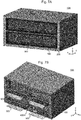
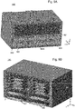
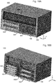
- FIGS 7-11 illustrate various example configurations of the multi-configuration bay 10 and different combinations of resource modules 600 installed therein.
- a first horizontal configuration of the multi-configuration bay 10 is illustrated.
- the adaptor 300 is included in the common bay 100, and no vertical dividers 300 are included.
- resource modules 600 having a width (excluding engagement features 610) of approximately d 4 such as the large resource module 603, would be installable horizontally within either compartment 250.
- each compartment 250 is filled with one a large resource module 603 that is horizontally oriented, for a total of two modules 603 in the multi-configuration bay 10.
- the large resource modules 603 could be accelerator modules, such as field-programmable-gate-array (FPGA) modules.
- FPGA field-programmable-gate-array
- one or both of the compartments 250 could have multiple resource modules installed therein, such as resource modules that have a width of d 4 but a height shorter than that of the large resource module 603.
- a horizontal midplane 400H is connected to a rear side of the common bay 100, and connectors 503 are connected to the midplane 400 so as to mate with connectors (not illustrated) on rear sides of the large resource modules 603.
- a second horizontal configuration of the multi-configuration bay 10 is illustrated.
- the adaptor 300 is included in the common bay 100, and two vertical dividers 300 are included (one in each compartment 250).
- any resource module 600 having a width (excluding engagement features 610) of approximately d 6 such as the reference resource modules 601 and the double-height resource modules 602, would be horizontally installable within the compartments 251. Any combination of such resource modules 600 could be used.
- Figs. 8A-B illustrate an example in which sixteen reference resource modules 601 are used.
- the reference resource modules 601 may be storage modules, such as hard-disk drive or solid state drive (SSD) modules.
- the reference resource modules 601 may adhere to the EDSFF form factor.
- the double height resource modules may be memory modules, such as storage-class-memory (SCM) modules. As illustrated in Figs.
- a horizontal midplane 400H is connected to a rear side of the common bay 100, and connectors 501 and/or 502 are connected to the midplane 400 so as to mate with connectors (not illustrated) on rear sides of the reference resource modules 601 and/or double-height resource modules 602.
- a third horizontal configuration of the multi-configuration bay 10 is illustrated.
- the adaptor 300 is included in the common bay 100, and one vertical divider 300 is included.
- the bay 10 has one compartment 250 having a width of d 4 and two sub-compartments 251 each having widths of d 6 (which also equals d 2 ).
- any resource modules 600 having a width (excluding engagement features 610) of approximately d 4 would be horizontally installable within the top compartment 250, while any resource modules 600 having a width (excluding engagement features 610) of approximately d 6 would be horizontally installable within either of the bottom sub-compartments 251.
- the top compartment 250 is filled with a large resource module 603, the bottom-left sub-compartment 251 is filled with two double-height resource modules 602, and the bottom-right sub-compartment 250 is filled with four reference resource modules 601.
- a horizontal midplane 400H is connected to a rear side of the common bay 100, and connectors 501-503 are connected to the midplane 400 so as to mate with connectors (not illustrated) on rear sides of the reference resource modules 601, double-height resource modules 602, and large resource modules 603, respectively.
- a first vertical configuration of the multi-configuration bay 10 is illustrated.
- the adaptor 300 is not installed in the common bay 100.
- the interior of the common bay 100 to configured to receive vertically oriented resource modules 600 using the first rails 100.
- resource module 600 having a width (excluding engagement features 610) of approximately d 2 , such as the reference resource modules 601 and double-height resource modules 602, would be installable within the common bay 100.
- ten reference resource modules 601 and four double-height resource modules 602 are installed in the common bay 100.
- a vertical midplane 400V is connected to a rear side of the common bay 100, and connectors 501 and 502 are connected to the midplane 400 so as to mate with connectors (not illustrated) on rear sides of the resource modules 601 and double-height resource modules 602, respectively.
- Fig. 12 illustrates one example computing device 1000 (also referred to as an electronic device) that includes an example multi-configuration bay 10.
- the computing device 1000 includes a chassis 710 and one or more multi-configuration bays 10 to house resource modules 600.
- multi-configuration bays 10 there are two multi-configuration bays 10 in the computing device 1000-a first multi-configuration bay 10D that is configured in the third horizontal configuration and a second multi-configuration bay 10F that is configured in the first vertical configuration.
- first multi-configuration bay 10D that is configured in the third horizontal configuration
- second multi-configuration bay 10F that is configured in the first vertical configuration.
- the multi-configuration bays 10 are to house resource modules 600 for processing units 810.
- the resource modules 600 are part of the computing device 1000, as illustrated in Fig. 12 . In other examples, the resource modules 600 may not yet be installed in the multi-configuration bays 10.
- the connectors 500 at the rear of the multi-configuration bays 10 may be to connect the resource modules 600 to the processing units 810 that are to utilize them.
- the processing units 810 may be housed in the same chassis 710 as the multi-configuration bays 10, as illustrated in Fig. 12 .
- the computing device 1000 may include one or more printed circuit boards 800 in the chassis 710 that includes one or more processing units 810, and the connectors 500 may be connected to the printed circuit board(s) 800 (for example, via cabling 550 and a connector 560 on the board(s) 800).
- the processing units 810 may be housed in a different chassis 710 and/or may be part of a different computing device 1000, in which case the resource modules 600 may be connected to the processing units 810 via a networking device (e.g., switch) or other inter-chassis interconnects that are connected to the connectors 500.
- a networking device e.g., switch
- other inter-chassis interconnects that are connected to the connectors 500.
- a "computer” is any electronic device that includes a processor and that is capable of executing programs comprising machine-readable instructions, including, for example, a server, a converged (or hyperconverged) appliance, a rack-scale system, some storage arrays, a personal computer, a laptop computer, a smartphone, a tablet, etc.
- an item means to have possession of and/or control over the item. This may include, for example, forming (or assembling) some or all of the item from its constituent materials and/or, obtaining possession of and/or control over an already-formed item.
Landscapes
- Engineering & Computer Science (AREA)
- Microelectronics & Electronic Packaging (AREA)
- Computer Hardware Design (AREA)
- General Engineering & Computer Science (AREA)
- Theoretical Computer Science (AREA)
- Power Engineering (AREA)
- Human Computer Interaction (AREA)
- Physics & Mathematics (AREA)
- General Physics & Mathematics (AREA)
- Cooling Or The Like Of Electrical Apparatus (AREA)
- Mounting Of Printed Circuit Boards And The Like (AREA)
- Casings For Electric Apparatus (AREA)
Claims (13)
- Mehrfachkonfigurationsschacht (10), das Folgendes umfasst:einen gemeinsamen Schacht (100), der eine obere Wand (101T), eine untere Wand (101B), eine erste Seitenwand (101L) und eine zweite Seitenwand (101R) und erste Schienen (110) an der oberen und unteren Wand (101T, 101B) beinhaltet, wobei die ersten Schienen (110) dazu konfiguriert sind, Ressourcenmodule in vertikal ausgerichteten eingebauten Positionen innerhalb des gemeinsamen Schachts (100) zu halten; undeinen Adapter (200), der innerhalb des gemeinsamen Schachts (100) einbaubar ist, wobei der Adapter (200) erste und zweite Seitenwände (205L, 205R) und zweite Schienen (210) an den ersten und zweiten Seitenwänden (205L, 205R) beinhaltet, wobei die zweiten Schienen (210) dazu konfiguriert sind, wenn der Adapter (200) in dem gemeinsamen Schacht (100) eingebaut ist, Ressourcenmodule in horizontal ausgerichteten eingebauten Positionen innerhalb des gemeinsamen Schachts (100) zu halten, wobei der Adapter (200) ferner Verriegelungen beinhaltet, die dazu konfiguriert sind, den Adapter (200) innerhalb des gemeinsamen Schachts (100) umkehrbar zu sichern, wobei der Adapter (200) von dem gemeinsamen Schacht (100) abnehmbar ist, wenn die Verriegelungen außer Eingriff gebracht werden, dadurch gekennzeichnet, dass die Verriegelungen erste und zweite Laschen (230) umfassen, wobei die ersten Laschen durch die erste Seitenwand (205L) des Adapters (200) und Schlitze (120) in der ersten Seitenwand (101L) des gemeinsamen Schachts (100) horizontal verschiebbar sind, und die zweiten Laschen (230) durch die zweite Seitenwand (205R) des Adapters (200) und Schlitze (120) in der zweiten Seitenwand (101R) des gemeinsamen Schachts (100) horizontal verschiebbar sind, so dass sie, wenn die Laschen (205) ausgestreckt sind, mit entsprechenden der Schlitze (120) zusammenpassen, um den Adapter (200) innerhalb des gemeinsamen Schachts (100) zu sichern.
- Mehrfachkonfigurationsschacht nach Anspruch 1, das ferner Folgendes umfasst:
einen vertikalen Teiler (300), der in dem gemeinsamen Schacht (100) zwischen der ersten und der zweiten Seitenwand (205I, 205R) des Adapters (200) einbaubar ist und der dritte Schienen (310) umfasst, die dazu konfiguriert sind, mit den zweiten Schienen (210) zusammenzuwirken, um Ressourcenmodule in horizontal ausgerichteten eingebauten Positionen zu halten. - Mehrfachkonfigurationsschacht nach Anspruch 2, wobei:(i) eine der ersten Schienen (110) eine Nut (112) darin beinhaltet, um eine Kante des vertikalen Teilers aufzunehmen, wenn der vertikale Teiler (300) in dem gemeinsamen Schacht (100) eingebaut ist; und/oder(ii) der Adapter (200) ferner eine horizontale Wand (201M) umfasst, die mit der ersten und der zweiten Seitenwand (205L, 205R) des Adapters (200) verbunden ist, wobei die horizontale Wand (201M) einen oder mehrere Schlitze (220) beinhaltet, um Laschen (320) des vertikalen Teilers (300) aufzunehmen, wenn der vertikale Teiler in dem gemeinsamen Schacht (100) eingebaut ist.
- Mehrfachkonfigurationsschacht nach Anspruch 1, das ferner Folgendes umfasst:
eine Mittelebene (400H), die dazu dient, mit einer Rückseite des gemeinsamen Schachts (100) verbunden zu werden, und die einen äußeren Rahmen (401), ein Netz (402), das mit dem äußeren Rahmen (401) verbunden ist, und Verbinderrahmen (405H) umfasst, die mit dem Netz verbunden sind und Öffnungen (406) in dem Netz definieren, wobei die Verbinderrahmen (405H) dazu konfiguriert sind, Kommunikationsverbinder aufzunehmen und zu halten, und gelegen sind, um mit den horizontal ausgerichteten eingebauten Positionen ausgerichtet zu sein, wenn die Mittelebene (400H) mit dem gemeinsamen Schacht (100) verbunden ist. - Mehrfachkonfigurationsschacht nach Anspruch 1, das ferner Folgendes umfasst:
eine vertikale Mittelebene (400V), die dazu dient, mit einer Rückseite des gemeinsamen Schachts (100) verbunden zu werden, und die einen äußeren Rahmen (401), ein Netz (402), das mit dem äußeren Rahmen (401) verbunden ist, und Verbinderrahmen (405V) beinhaltet, die mit dem Netz verbunden sind und Öffnungen (406) in dem Netz definieren, wobei die Verbinderrahmen (405V) dazu konfiguriert sind, Kommunikationsverbinder aufzunehmen und zu halten, und gelegen sind, um mit den vertikal ausgerichteten eingebauten Positionen ausgerichtet zu sein, wenn die vertikale Mittelebene (400) mit dem gemeinsamen Schacht (100) verbunden ist. - Mehrfachkonfigurationsschacht nach Anspruch 1, wobei der Adapter (200) eine horizontale Wand (201M), die mit der ersten und zweiten Seitenwand (205L, 205R) des Adapters (200) verbunden ist, eine untere Spannweite (203B), die mit den unteren vorderen Ecken der ersten und zweiten Seitenwand (205L, 205R) des Adapters (200) verbunden ist und EMI-Kontakte beinhaltet, und eine obere Spannweite (203T) beinhaltet, die mit den oberen vorderen Ecken der ersten und zweiten Seitenwand (205L, 205R) des Adapters (200) verbunden ist und zusätzliche EMI-Kontakte beinhaltet.
- Elektronische Vorrichtung, die Folgendes umfasst:
ein Chassis (710), den Mehrfachkonfigurationsschacht (10) nach Anspruch 1, der in dem Chassis angeordnet ist, wobei der Adapter (200) in dem gemeinsamen Schacht (100) eingebaut ist, und Ressourcenmodule, die in dem Mehrfachkonfigurationsschacht in den horizontal ausgerichteten Installationspositionen eingebaut sind. - Elektronische Vorrichtung nach Anspruch 7, die ferner Folgendes umfasst:(i) einen vertikalen Teiler (300), der in dem gemeinsamen Schacht (100) zwischen der ersten und der zweiten Seitenwand (205L, 205R) des Adapters angeordnet ist und dritte Schienen (310) umfasst, die dazu konfiguriert sind, mit den zweiten Schienen (210) zusammenzuwirken, um Ressourcenmodule in horizontal ausgerichteten eingebauten Positionen zu halten; und(ii) eine Mittelebene (400H), die mit einer Rückseite des gemeinsamen Schachts (100) verbunden ist und die einen äußeren Rahmen (401), ein Netz (402), das mit dem äußeren Rahmen (401) verbunden ist, und Verbinderrahmen (405H) umfasst, die mit dem Netz (402) verbunden sind und Öffnungen (406) in diesem definieren, wobei die Verbinderrahmen (405H) Kommunikationsverbinder halten, die mit den eingebauten Ressourcenmodulen verbunden sind.
- Elektronische Vorrichtung nach Anspruch 7, wobei der Adapter eine horizontale Wand (201M) beinhaltet, die mit der ersten und zweiten Seitenwand (205L, 205R) des Adapters (200) verbunden ist und den gemeinsamen Schacht (100) in zwei Fächer voller Breite unterteilt.
- Elektronische Vorrichtung nach Anspruch 9, die ferner Folgendes umfasst:
einen oder mehrere vertikale Teiler (300), die zwischen der ersten und zweiten Seitenwand (205L, 205R) des Adapters (200) und zwischen einer Bodenwand (101B) des gemeinsamen Schachts (100) und der Horizontalwand (201M) des Adapters angeordnet sind und die ein oder beide Fächer voller Breite in zwei oder mehrere Fächer teilweiser Breite unterteilen. - Verfahren zum Herstellen einer elektronischen Vorrichtung, das Folgendes umfasst:
Bereitstellen eines Chassis (710), Bereitstellen des Mehrfachkonfigurationsschachts (10) nach Anspruch 1, Identifizieren einer gewünschten Konfiguration für Ressourcenmodule in der elektronischen Vorrichtung, Einbauen des gemeinsamen Schachts (10) in dem Chassis (710) und Bestimmen, ob der Adapter (200) in dem gemeinsamen Schacht (100) basierend auf der gewünschten Konfiguration einzubauen ist. - Verfahren nach Anspruch 11, das ferner Folgendes umfasst:
als Reaktion auf die gewünschte Konfiguration, die horizontal ausgerichtete Ressourcenmodule in dem Mehrfachkonfigurationsschacht beinhaltet, Einbauen des Adapters (200) in dem gemeinsamen Schacht (100) oder, als Reaktion auf die gewünschte Konfiguration, die vertikal ausgerichtete Ressourcenmodule in dem Mehrfachkonfigurationsschacht beinhaltet, Nicht-Einbauen des Adapters (200) in dem gemeinsamen Schacht (100). - Verfahren nach Anspruch 11, wobei der Mehrfachkonfigurationsschacht eine Mittelebene (400H) und eine vertikale Mittelebene (400V) beinhaltet, die beide dazu konfiguriert sind, mit einer Rückseite des gemeinsamen Schachts (100) verbunden zu werden, und einen äußeren Rahmen (401), ein mit dem äußeren Rahmen (401) verbundenes Netz (402) und Verbinderrahmen (405H, 405V) beinhalten, die mit Öffnungen (406) im Netz (402) verbunden sind und diese definieren, wobei die Verbinderrahmen (405H) der Mittelebene (400H) dazu konfiguriert sind, Gen-Z-Verbinder aufzunehmen und zu halten, und gelegen sind, um mit den horizontal ausgerichtetenteingebauten Positionen ausgerichtet zu sein; die Verbinderrahmen der vertikalen Mittelebene (400V) konfiguriert sind, Gen-Z-Verbinder aufzunehmen und zu halten, und gelegen sind, um mit den vertikal ausgerichtetenteingebauten Positionen ausgerichtet zu sein; und
wobei das Verfahren ferner ein Bestimmen umfasst, ob die Mittelebene (400H) oder die vertikale Mittelebene (400V) mit dem gemeinsamen Schacht (100) basierend auf der gewünschten Konfiguration verbunden werden soll.
Applications Claiming Priority (1)
| Application Number | Priority Date | Filing Date | Title |
|---|---|---|---|
| US16/021,658 US10264701B1 (en) | 2018-06-28 | 2018-06-28 | Multi-configuration resource module bay |
Publications (2)
| Publication Number | Publication Date |
|---|---|
| EP3589097A1 EP3589097A1 (de) | 2020-01-01 |
| EP3589097B1 true EP3589097B1 (de) | 2020-11-18 |
Family
ID=66098692
Family Applications (1)
| Application Number | Title | Priority Date | Filing Date |
|---|---|---|---|
| EP19183075.1A Active EP3589097B1 (de) | 2018-06-28 | 2019-06-27 | Multikonfigurationsressourcenmodulschacht |
Country Status (3)
| Country | Link |
|---|---|
| US (1) | US10264701B1 (de) |
| EP (1) | EP3589097B1 (de) |
| CN (1) | CN110658896B (de) |
Families Citing this family (16)
| Publication number | Priority date | Publication date | Assignee | Title |
|---|---|---|---|---|
| US11238005B2 (en) | 2018-07-20 | 2022-02-01 | Samsung Electronics Co., Ltd. | SFF-TA-100X based multi-mode protocols solid state devices |
| JP6947766B2 (ja) * | 2019-02-13 | 2021-10-13 | ファナック株式会社 | 電子装置 |
| JP6947765B2 (ja) | 2019-02-13 | 2021-10-13 | ファナック株式会社 | フェイスプレート、および電子装置 |
| US11483943B2 (en) * | 2020-04-30 | 2022-10-25 | Hewlett Packard Enterprise Development Lp | Computing device |
| US11930612B2 (en) * | 2021-08-06 | 2024-03-12 | Dell Products L.P. | Configurable multi-orientation device mount rack system |
| US11997822B2 (en) * | 2021-10-25 | 2024-05-28 | Dell Products L.P. | Modular design to support variable configurations of front chassis modules |
| CN117631771A (zh) * | 2022-08-19 | 2024-03-01 | 纬联电子科技(中山)有限公司 | 电子装置及其支架 |
| US12443250B2 (en) | 2023-01-30 | 2025-10-14 | Hewlett Packard Enterprise Development Lp | Electronic device having keying mechanisms for a drive carrier and a drive cage |
| CN219916273U (zh) * | 2023-01-30 | 2023-10-27 | 富联精密电子(天津)有限公司 | 数据存储器固定装置和机箱 |
| CN116301230A (zh) * | 2023-03-06 | 2023-06-23 | 英业达科技有限公司 | 硬盘模块、硬盘架组及服务器 |
| US12610495B2 (en) * | 2023-04-13 | 2026-04-21 | Hewlett Packard Enterprise Development Lp | Chassis having trays to mount different form factor electronic modules to an electronic device |
| US20240365497A1 (en) * | 2023-04-25 | 2024-10-31 | Dell Products L.P. | Server System Configurable Bay Device Mounting System |
| US20240370066A1 (en) * | 2023-05-04 | 2024-11-07 | Dell Products L.P. | Form Factor Adapter for Information Handling System Add-In Cards |
| US12295122B2 (en) | 2023-05-10 | 2025-05-06 | Bae Systems Information And Electronic Systems Integration Inc. | Coolant flow partition for cooling 3U boards in 6U chassis |
| US12557235B2 (en) * | 2024-01-12 | 2026-02-17 | Dell Products L.P. | Multi-device rack width adapter system |
| US20250294698A1 (en) * | 2024-03-12 | 2025-09-18 | Hewlett Packard Enterprise Development Lp | Chassis of an information processing device having modular panel section |
Family Cites Families (26)
| Publication number | Priority date | Publication date | Assignee | Title |
|---|---|---|---|---|
| US3807572A (en) * | 1972-05-12 | 1974-04-30 | Pitney Bowes Inc | Adjustable compartment size storage unit |
| DE2936499C2 (de) * | 1979-09-10 | 1983-11-03 | Rolf Wolfgang 6920 Sinsheim Binder | Schaltungsgehäuse. |
| US5248193A (en) * | 1991-10-18 | 1993-09-28 | Texas Microsystems, Inc. | Extruded enclosure for a computer system |
| US5235493A (en) * | 1992-05-15 | 1993-08-10 | Sinotek International Co., Ltd. | Alternately horizontal or vertical computer main frame housing |
| CA2097476C (en) * | 1993-06-01 | 1997-07-01 | Joseph Germain Maurice Paul Girard | Computer case with adjustable drive housing for interchangeable desktop/tower configuration |
| DE9308494U1 (de) | 1993-06-07 | 1993-09-23 | Enslin, Andreas, 80339 München | Aufbewahrungseinschub fuer pc-gehaeuse |
| US5587877A (en) * | 1994-10-26 | 1996-12-24 | Amco Engineering Co. | Computer organizer enclosure and method |
| US5724227A (en) * | 1996-03-19 | 1998-03-03 | Gateway 2000, Inc. | Rotatable drive bay module for a computer cabinet |
| US6075694A (en) * | 1997-07-11 | 2000-06-13 | Dell Usa L.P. | Drive bay for alternately orientable computer chassis |
| US6122173A (en) * | 1998-03-11 | 2000-09-19 | Compaq Computer Corporation | Drive latch mechanism for computer selectively configurable in both desktop and tower orientations |
| US6362955B2 (en) | 1998-03-11 | 2002-03-26 | Compaq Computer Corporation | Computer selectively configurable in both desktop and tower orientations |
| DE19917406A1 (de) | 1999-04-16 | 2000-10-26 | Esk Ind Elektronik Gmbh | Computergehäuse |
| US6548753B1 (en) * | 2000-06-06 | 2003-04-15 | Marconi Communications, Inc. | Flame suppression cabinet |
| WO2005004569A2 (en) * | 2003-06-27 | 2005-01-13 | Molex Incorporated | Improvements in adapter module retention latches |
| US7200003B2 (en) * | 2004-12-23 | 2007-04-03 | Dell Products L.P. | Method and apparatus for mounting a drive in a chassis |
| US7190574B2 (en) * | 2005-02-24 | 2007-03-13 | Dell Products L.P. | Method and apparatus for securing a modular component in a chassis |
| US7418181B2 (en) * | 2006-02-13 | 2008-08-26 | Adc Telecommunications, Inc. | Fiber optic splitter module |
| US7469978B2 (en) * | 2006-08-09 | 2008-12-30 | Super Micro Computer, Inc. | Block-shape container which can be assembled into and disassembled from a computer casing |
| US7639486B2 (en) * | 2007-12-13 | 2009-12-29 | International Business Machines Corporation | Rack system providing flexible configuration of computer systems with front access |
| TW201223404A (en) * | 2010-11-17 | 2012-06-01 | Hon Hai Prec Ind Co Ltd | Fixing frame for hard disk |
| EP2874560B1 (de) * | 2012-07-23 | 2019-11-06 | 3M Innovative Properties Company | Selbstligierende kieferorthopädische klammer |
| US8915557B2 (en) * | 2012-09-21 | 2014-12-23 | Dell Products, Lp | Locking mechanism for adaptor assembly of a server rack chassis |
| RU2675131C2 (ru) * | 2013-10-14 | 2018-12-17 | Везувиус Груп (Са) | Соединительное устройство для двустороннего соединения защитной трубы разливочного ковша со стаканом-коллектором, самоподдерживающаяся защитная труба разливочного ковша, их узел и способ соединения защитной трубы разливочного ковша со стаканом-коллектором |
| US9167716B2 (en) * | 2013-12-13 | 2015-10-20 | Dell Products, Lp | Blade server chassis bay divider |
| CN203748129U (zh) * | 2013-12-27 | 2014-07-30 | 武汉龙安集团有限责任公司 | 适用于总线集成的模块化机柜 |
| US10244651B2 (en) * | 2017-05-25 | 2019-03-26 | Dell Products L.P. | Multi-form factor power supply bay system |
-
2018
- 2018-06-28 US US16/021,658 patent/US10264701B1/en active Active
-
2019
- 2019-06-26 CN CN201910562303.5A patent/CN110658896B/zh active Active
- 2019-06-27 EP EP19183075.1A patent/EP3589097B1/de active Active
Non-Patent Citations (1)
| Title |
|---|
| None * |
Also Published As
| Publication number | Publication date |
|---|---|
| CN110658896A (zh) | 2020-01-07 |
| EP3589097A1 (de) | 2020-01-01 |
| US10264701B1 (en) | 2019-04-16 |
| CN110658896B (zh) | 2024-03-08 |
Similar Documents
| Publication | Publication Date | Title |
|---|---|---|
| US10264701B1 (en) | Multi-configuration resource module bay | |
| US10042396B1 (en) | Configurable module guides for modular electronic system | |
| EP3669251B1 (de) | Konfigurierbare modulführungen für modulares elektronisches system | |
| US6018456A (en) | Enclosure for removable computer peripheral equipment | |
| US7210586B2 (en) | Adapter element for card cage system | |
| US8328026B2 (en) | Apparatus and method for configuring a dual rack-mountable chassis | |
| US9179572B2 (en) | Server | |
| US9865980B2 (en) | Multi-node server platform | |
| US7167380B2 (en) | Card cage system | |
| US20090097200A1 (en) | Modular blade for providing scalable mechanical, electrical and environmental functionality in the enterprise using advancedtca boards | |
| US7277296B2 (en) | Card cage system | |
| US9483089B2 (en) | System and method for integrating multiple servers into single full height bay of a server rack chassis | |
| US10383247B2 (en) | High density chassis for a server rack | |
| EP0889681A2 (de) | Modulares Turmsystem | |
| CN104756618B (zh) | 模块式机架系统 | |
| US7660108B2 (en) | Apparatus for positioning electronic component modules within an equipment chassis | |
| US20080174948A1 (en) | Data storage device enclosures, a midplane, a method of manufacturing a midplane and modules | |
| TWI806558B (zh) | 尺型裝置模組以及計算系統 | |
| US10869405B1 (en) | Routing power and data cables to information handling system racks in a data center | |
| CN215729605U (zh) | 服务器机箱 | |
| CN103988590B (zh) | 用于计算模块的可再配置的搁架 | |
| GB2511169A (en) | Electronics structure comprising at least one barrier impermeable to fine particles | |
| CN215729603U (zh) | 服务器机箱 | |
| US20130341293A1 (en) | Fastening device for hard disk drive | |
| CN120659270A (zh) | 信息处理装置的具有模块化面板区段的机架 |
Legal Events
| Date | Code | Title | Description |
|---|---|---|---|
| PUAI | Public reference made under article 153(3) epc to a published international application that has entered the european phase |
Free format text: ORIGINAL CODE: 0009012 |
|
| STAA | Information on the status of an ep patent application or granted ep patent |
Free format text: STATUS: THE APPLICATION HAS BEEN PUBLISHED |
|
| AK | Designated contracting states |
Kind code of ref document: A1 Designated state(s): AL AT BE BG CH CY CZ DE DK EE ES FI FR GB GR HR HU IE IS IT LI LT LU LV MC MK MT NL NO PL PT RO RS SE SI SK SM TR |
|
| AX | Request for extension of the european patent |
Extension state: BA ME |
|
| STAA | Information on the status of an ep patent application or granted ep patent |
Free format text: STATUS: REQUEST FOR EXAMINATION WAS MADE |
|
| GRAP | Despatch of communication of intention to grant a patent |
Free format text: ORIGINAL CODE: EPIDOSNIGR1 |
|
| STAA | Information on the status of an ep patent application or granted ep patent |
Free format text: STATUS: GRANT OF PATENT IS INTENDED |
|
| 17P | Request for examination filed |
Effective date: 20200610 |
|
| RBV | Designated contracting states (corrected) |
Designated state(s): AL AT BE BG CH CY CZ DE DK EE ES FI FR GB GR HR HU IE IS IT LI LT LU LV MC MK MT NL NO PL PT RO RS SE SI SK SM TR |
|
| RIC1 | Information provided on ipc code assigned before grant |
Ipc: A47B 57/08 20060101ALI20200623BHEP Ipc: H05K 7/14 20060101AFI20200623BHEP Ipc: A47B 57/58 20060101ALI20200623BHEP |
|
| INTG | Intention to grant announced |
Effective date: 20200710 |
|
| RIN1 | Information on inventor provided before grant (corrected) |
Inventor name: NORTON, JOHN |
|
| GRAS | Grant fee paid |
Free format text: ORIGINAL CODE: EPIDOSNIGR3 |
|
| GRAA | (expected) grant |
Free format text: ORIGINAL CODE: 0009210 |
|
| STAA | Information on the status of an ep patent application or granted ep patent |
Free format text: STATUS: THE PATENT HAS BEEN GRANTED |
|
| AK | Designated contracting states |
Kind code of ref document: B1 Designated state(s): AL AT BE BG CH CY CZ DE DK EE ES FI FR GB GR HR HU IE IS IT LI LT LU LV MC MK MT NL NO PL PT RO RS SE SI SK SM TR |
|
| REG | Reference to a national code |
Ref country code: GB Ref legal event code: FG4D |
|
| REG | Reference to a national code |
Ref country code: CH Ref legal event code: EP |
|
| REG | Reference to a national code |
Ref country code: IE Ref legal event code: FG4D |
|
| REG | Reference to a national code |
Ref country code: DE Ref legal event code: R096 Ref document number: 602019001366 Country of ref document: DE |
|
| REG | Reference to a national code |
Ref country code: AT Ref legal event code: REF Ref document number: 1337180 Country of ref document: AT Kind code of ref document: T Effective date: 20201215 |
|
| REG | Reference to a national code |
Ref country code: AT Ref legal event code: MK05 Ref document number: 1337180 Country of ref document: AT Kind code of ref document: T Effective date: 20201118 |
|
| REG | Reference to a national code |
Ref country code: NL Ref legal event code: MP Effective date: 20201118 |
|
| PG25 | Lapsed in a contracting state [announced via postgrant information from national office to epo] |
Ref country code: GR Free format text: LAPSE BECAUSE OF FAILURE TO SUBMIT A TRANSLATION OF THE DESCRIPTION OR TO PAY THE FEE WITHIN THE PRESCRIBED TIME-LIMIT Effective date: 20210219 Ref country code: NO Free format text: LAPSE BECAUSE OF FAILURE TO SUBMIT A TRANSLATION OF THE DESCRIPTION OR TO PAY THE FEE WITHIN THE PRESCRIBED TIME-LIMIT Effective date: 20210218 Ref country code: FI Free format text: LAPSE BECAUSE OF FAILURE TO SUBMIT A TRANSLATION OF THE DESCRIPTION OR TO PAY THE FEE WITHIN THE PRESCRIBED TIME-LIMIT Effective date: 20201118 Ref country code: PT Free format text: LAPSE BECAUSE OF FAILURE TO SUBMIT A TRANSLATION OF THE DESCRIPTION OR TO PAY THE FEE WITHIN THE PRESCRIBED TIME-LIMIT Effective date: 20210318 Ref country code: RS Free format text: LAPSE BECAUSE OF FAILURE TO SUBMIT A TRANSLATION OF THE DESCRIPTION OR TO PAY THE FEE WITHIN THE PRESCRIBED TIME-LIMIT Effective date: 20201118 |
|
| PG25 | Lapsed in a contracting state [announced via postgrant information from national office to epo] |
Ref country code: AT Free format text: LAPSE BECAUSE OF FAILURE TO SUBMIT A TRANSLATION OF THE DESCRIPTION OR TO PAY THE FEE WITHIN THE PRESCRIBED TIME-LIMIT Effective date: 20201118 Ref country code: BG Free format text: LAPSE BECAUSE OF FAILURE TO SUBMIT A TRANSLATION OF THE DESCRIPTION OR TO PAY THE FEE WITHIN THE PRESCRIBED TIME-LIMIT Effective date: 20210218 Ref country code: PL Free format text: LAPSE BECAUSE OF FAILURE TO SUBMIT A TRANSLATION OF THE DESCRIPTION OR TO PAY THE FEE WITHIN THE PRESCRIBED TIME-LIMIT Effective date: 20201118 Ref country code: IS Free format text: LAPSE BECAUSE OF FAILURE TO SUBMIT A TRANSLATION OF THE DESCRIPTION OR TO PAY THE FEE WITHIN THE PRESCRIBED TIME-LIMIT Effective date: 20210318 Ref country code: LV Free format text: LAPSE BECAUSE OF FAILURE TO SUBMIT A TRANSLATION OF THE DESCRIPTION OR TO PAY THE FEE WITHIN THE PRESCRIBED TIME-LIMIT Effective date: 20201118 Ref country code: SE Free format text: LAPSE BECAUSE OF FAILURE TO SUBMIT A TRANSLATION OF THE DESCRIPTION OR TO PAY THE FEE WITHIN THE PRESCRIBED TIME-LIMIT Effective date: 20201118 |
|
| REG | Reference to a national code |
Ref country code: LT Ref legal event code: MG9D |
|
| PG25 | Lapsed in a contracting state [announced via postgrant information from national office to epo] |
Ref country code: HR Free format text: LAPSE BECAUSE OF FAILURE TO SUBMIT A TRANSLATION OF THE DESCRIPTION OR TO PAY THE FEE WITHIN THE PRESCRIBED TIME-LIMIT Effective date: 20201118 |
|
| PG25 | Lapsed in a contracting state [announced via postgrant information from national office to epo] |
Ref country code: LT Free format text: LAPSE BECAUSE OF FAILURE TO SUBMIT A TRANSLATION OF THE DESCRIPTION OR TO PAY THE FEE WITHIN THE PRESCRIBED TIME-LIMIT Effective date: 20201118 Ref country code: RO Free format text: LAPSE BECAUSE OF FAILURE TO SUBMIT A TRANSLATION OF THE DESCRIPTION OR TO PAY THE FEE WITHIN THE PRESCRIBED TIME-LIMIT Effective date: 20201118 Ref country code: CZ Free format text: LAPSE BECAUSE OF FAILURE TO SUBMIT A TRANSLATION OF THE DESCRIPTION OR TO PAY THE FEE WITHIN THE PRESCRIBED TIME-LIMIT Effective date: 20201118 Ref country code: EE Free format text: LAPSE BECAUSE OF FAILURE TO SUBMIT A TRANSLATION OF THE DESCRIPTION OR TO PAY THE FEE WITHIN THE PRESCRIBED TIME-LIMIT Effective date: 20201118 Ref country code: SM Free format text: LAPSE BECAUSE OF FAILURE TO SUBMIT A TRANSLATION OF THE DESCRIPTION OR TO PAY THE FEE WITHIN THE PRESCRIBED TIME-LIMIT Effective date: 20201118 Ref country code: SK Free format text: LAPSE BECAUSE OF FAILURE TO SUBMIT A TRANSLATION OF THE DESCRIPTION OR TO PAY THE FEE WITHIN THE PRESCRIBED TIME-LIMIT Effective date: 20201118 |
|
| REG | Reference to a national code |
Ref country code: DE Ref legal event code: R097 Ref document number: 602019001366 Country of ref document: DE |
|
| PG25 | Lapsed in a contracting state [announced via postgrant information from national office to epo] |
Ref country code: DK Free format text: LAPSE BECAUSE OF FAILURE TO SUBMIT A TRANSLATION OF THE DESCRIPTION OR TO PAY THE FEE WITHIN THE PRESCRIBED TIME-LIMIT Effective date: 20201118 |
|
| PLBE | No opposition filed within time limit |
Free format text: ORIGINAL CODE: 0009261 |
|
| STAA | Information on the status of an ep patent application or granted ep patent |
Free format text: STATUS: NO OPPOSITION FILED WITHIN TIME LIMIT |
|
| 26N | No opposition filed |
Effective date: 20210819 |
|
| PG25 | Lapsed in a contracting state [announced via postgrant information from national office to epo] |
Ref country code: NL Free format text: LAPSE BECAUSE OF FAILURE TO SUBMIT A TRANSLATION OF THE DESCRIPTION OR TO PAY THE FEE WITHIN THE PRESCRIBED TIME-LIMIT Effective date: 20201118 Ref country code: AL Free format text: LAPSE BECAUSE OF FAILURE TO SUBMIT A TRANSLATION OF THE DESCRIPTION OR TO PAY THE FEE WITHIN THE PRESCRIBED TIME-LIMIT Effective date: 20201118 Ref country code: IT Free format text: LAPSE BECAUSE OF FAILURE TO SUBMIT A TRANSLATION OF THE DESCRIPTION OR TO PAY THE FEE WITHIN THE PRESCRIBED TIME-LIMIT Effective date: 20201118 |
|
| PG25 | Lapsed in a contracting state [announced via postgrant information from national office to epo] |
Ref country code: SI Free format text: LAPSE BECAUSE OF FAILURE TO SUBMIT A TRANSLATION OF THE DESCRIPTION OR TO PAY THE FEE WITHIN THE PRESCRIBED TIME-LIMIT Effective date: 20201118 |
|
| PG25 | Lapsed in a contracting state [announced via postgrant information from national office to epo] |
Ref country code: ES Free format text: LAPSE BECAUSE OF FAILURE TO SUBMIT A TRANSLATION OF THE DESCRIPTION OR TO PAY THE FEE WITHIN THE PRESCRIBED TIME-LIMIT Effective date: 20201118 Ref country code: MC Free format text: LAPSE BECAUSE OF FAILURE TO SUBMIT A TRANSLATION OF THE DESCRIPTION OR TO PAY THE FEE WITHIN THE PRESCRIBED TIME-LIMIT Effective date: 20201118 |
|
| REG | Reference to a national code |
Ref country code: BE Ref legal event code: MM Effective date: 20210630 |
|
| PG25 | Lapsed in a contracting state [announced via postgrant information from national office to epo] |
Ref country code: LU Free format text: LAPSE BECAUSE OF NON-PAYMENT OF DUE FEES Effective date: 20210627 |
|
| PG25 | Lapsed in a contracting state [announced via postgrant information from national office to epo] |
Ref country code: IE Free format text: LAPSE BECAUSE OF NON-PAYMENT OF DUE FEES Effective date: 20210627 |
|
| PG25 | Lapsed in a contracting state [announced via postgrant information from national office to epo] |
Ref country code: IS Free format text: LAPSE BECAUSE OF FAILURE TO SUBMIT A TRANSLATION OF THE DESCRIPTION OR TO PAY THE FEE WITHIN THE PRESCRIBED TIME-LIMIT Effective date: 20210318 Ref country code: FR Free format text: LAPSE BECAUSE OF NON-PAYMENT OF DUE FEES Effective date: 20210630 |
|
| PG25 | Lapsed in a contracting state [announced via postgrant information from national office to epo] |
Ref country code: BE Free format text: LAPSE BECAUSE OF NON-PAYMENT OF DUE FEES Effective date: 20210630 |
|
| REG | Reference to a national code |
Ref country code: DE Ref legal event code: R081 Ref document number: 602019001366 Country of ref document: DE Owner name: HEWLETT PACKARD ENTERPRISE DEVELOPMENT LP, SPR, US Free format text: FORMER OWNER: HEWLETT PACKARD ENTERPRISE DEVELOPMENT LP, HOUSTON, TEX., US Ref country code: DE Ref legal event code: R082 Ref document number: 602019001366 Country of ref document: DE Representative=s name: MARKS & CLERK (LUXEMBOURG) LLP, LU |
|
| REG | Reference to a national code |
Ref country code: CH Ref legal event code: PL |
|
| PG25 | Lapsed in a contracting state [announced via postgrant information from national office to epo] |
Ref country code: LI Free format text: LAPSE BECAUSE OF NON-PAYMENT OF DUE FEES Effective date: 20220630 Ref country code: CH Free format text: LAPSE BECAUSE OF NON-PAYMENT OF DUE FEES Effective date: 20220630 |
|
| PG25 | Lapsed in a contracting state [announced via postgrant information from national office to epo] |
Ref country code: CY Free format text: LAPSE BECAUSE OF FAILURE TO SUBMIT A TRANSLATION OF THE DESCRIPTION OR TO PAY THE FEE WITHIN THE PRESCRIBED TIME-LIMIT Effective date: 20201118 |
|
| PG25 | Lapsed in a contracting state [announced via postgrant information from national office to epo] |
Ref country code: HU Free format text: LAPSE BECAUSE OF FAILURE TO SUBMIT A TRANSLATION OF THE DESCRIPTION OR TO PAY THE FEE WITHIN THE PRESCRIBED TIME-LIMIT; INVALID AB INITIO Effective date: 20190627 |
|
| GBPC | Gb: european patent ceased through non-payment of renewal fee |
Effective date: 20230627 |
|
| PG25 | Lapsed in a contracting state [announced via postgrant information from national office to epo] |
Ref country code: MK Free format text: LAPSE BECAUSE OF FAILURE TO SUBMIT A TRANSLATION OF THE DESCRIPTION OR TO PAY THE FEE WITHIN THE PRESCRIBED TIME-LIMIT Effective date: 20201118 Ref country code: GB Free format text: LAPSE BECAUSE OF NON-PAYMENT OF DUE FEES Effective date: 20230627 |
|
| PG25 | Lapsed in a contracting state [announced via postgrant information from national office to epo] |
Ref country code: MT Free format text: LAPSE BECAUSE OF FAILURE TO SUBMIT A TRANSLATION OF THE DESCRIPTION OR TO PAY THE FEE WITHIN THE PRESCRIBED TIME-LIMIT Effective date: 20201118 |
|
| PGFP | Annual fee paid to national office [announced via postgrant information from national office to epo] |
Ref country code: DE Payment date: 20250626 Year of fee payment: 7 |
|
| PG25 | Lapsed in a contracting state [announced via postgrant information from national office to epo] |
Ref country code: TR Free format text: LAPSE BECAUSE OF FAILURE TO SUBMIT A TRANSLATION OF THE DESCRIPTION OR TO PAY THE FEE WITHIN THE PRESCRIBED TIME-LIMIT Effective date: 20201118 |