EP3589111B1 - Verbesserte reduzierung von radspuren für roboterrasenmäher - Google Patents
Verbesserte reduzierung von radspuren für roboterrasenmäher Download PDFInfo
- Publication number
- EP3589111B1 EP3589111B1 EP18761934.1A EP18761934A EP3589111B1 EP 3589111 B1 EP3589111 B1 EP 3589111B1 EP 18761934 A EP18761934 A EP 18761934A EP 3589111 B1 EP3589111 B1 EP 3589111B1
- Authority
- EP
- European Patent Office
- Prior art keywords
- robotic lawnmower
- cable
- distance
- signal quality
- quality level
- Prior art date
- Legal status (The legal status is an assumption and is not a legal conclusion. Google has not performed a legal analysis and makes no representation as to the accuracy of the status listed.)
- Active
Links
Images


Classifications
-
- G—PHYSICS
- G05—CONTROLLING; REGULATING
- G05D—SYSTEMS FOR CONTROLLING OR REGULATING NON-ELECTRIC VARIABLES
- G05D1/00—Control of position, course, altitude or attitude of land, water, air or space vehicles, e.g. using automatic pilots
- G05D1/20—Control system inputs
- G05D1/24—Arrangements for determining position or orientation
- G05D1/244—Arrangements for determining position or orientation using passive navigation aids external to the vehicle, e.g. markers, reflectors or magnetic means
-
- G—PHYSICS
- G05—CONTROLLING; REGULATING
- G05D—SYSTEMS FOR CONTROLLING OR REGULATING NON-ELECTRIC VARIABLES
- G05D1/00—Control of position, course, altitude or attitude of land, water, air or space vehicles, e.g. using automatic pilots
- G05D1/02—Control of position or course in two dimensions
- G05D1/021—Control of position or course in two dimensions specially adapted to land vehicles
- G05D1/0259—Control of position or course in two dimensions specially adapted to land vehicles using magnetic or electromagnetic means
- G05D1/0265—Control of position or course in two dimensions specially adapted to land vehicles using magnetic or electromagnetic means using buried wires
-
- A—HUMAN NECESSITIES
- A01—AGRICULTURE; FORESTRY; ANIMAL HUSBANDRY; HUNTING; TRAPPING; FISHING
- A01D—HARVESTING; MOWING
- A01D34/00—Mowers; Mowing apparatus of harvesters
- A01D34/006—Control or measuring arrangements
- A01D34/008—Control or measuring arrangements for automated or remotely controlled operation
-
- A—HUMAN NECESSITIES
- A01—AGRICULTURE; FORESTRY; ANIMAL HUSBANDRY; HUNTING; TRAPPING; FISHING
- A01D—HARVESTING; MOWING
- A01D34/00—Mowers; Mowing apparatus of harvesters
- A01D34/01—Mowers; Mowing apparatus of harvesters characterised by features relating to the type of cutting apparatus
- A01D34/412—Mowers; Mowing apparatus of harvesters characterised by features relating to the type of cutting apparatus having rotating cutters
- A01D34/63—Mowers; Mowing apparatus of harvesters characterised by features relating to the type of cutting apparatus having rotating cutters having cutters rotating about a vertical axis
- A01D34/64—Mowers; Mowing apparatus of harvesters characterised by features relating to the type of cutting apparatus having rotating cutters having cutters rotating about a vertical axis mounted on a vehicle, e.g. a tractor, or drawn by an animal or a vehicle
-
- G—PHYSICS
- G05—CONTROLLING; REGULATING
- G05D—SYSTEMS FOR CONTROLLING OR REGULATING NON-ELECTRIC VARIABLES
- G05D1/00—Control of position, course, altitude or attitude of land, water, air or space vehicles, e.g. using automatic pilots
- G05D1/60—Intended control result
- G05D1/648—Performing a task within a working area or space, e.g. cleaning
Definitions
- This application relates to robotic lawnmowers and in particular to a system and a method for performing improved reduction of wheel tracks in a work area.
- Automated or robotic power tools such as robotic lawnmowers are becoming increasingly more popular.
- a work area such as a garden
- the robotic lawnmower is typically configured to follow the boundary wire or a guide cable when searching for its charging station.
- wheel tracks are here to be understood to not only include actual tracks made by wheels, but also the area under the robotic lawnmower as it moves along the cable, which will be cut more often than other areas of the work area, thus forming more or less distinct tracks showing where the robotic lawnmower has travelled.
- the robotic lawnmower is configured to follow the boundary cable (and/or guide cable) at a distance. By varying the distance from time to time or each time the robotic lawnmower travels to the charging station - or also out from the charging station - a reduction in wheel tracks may be achieved.
- US2012/0029756 A1, 2 February 2012 discloses a robotic mower and a charging station connected to a boundary wire, a boundary drive circuit driving signals on the boundary wire.
- the robotic mower has a boundary wire sensor to detect the signal and provide a further signal to a vehicle control unit to indicate the distance of the sensor to the boundary wire.
- the vehicle control unit may use input from the boundary sensor to direct the traction wheel motors to follow a path at a specified distance parallel to the boundary wire.
- the vehicle control unit may specify a return path that is offset from the main boundary wire.
- the vehicle control unit may determine the desired offset from the boundary wire based on a random or an incremented variable.
- the robotic lawnmower is instead configured to follow the cable based on the received signal strength which enables for a safer and more reliable navigation.
- a robotic lawnmower system comprising a robotic lawnmower and a signal generator to which a cable is to be connected, the signal generator being configured to transmit a signal through the cable.
- the robotic lawnmower comprises: a sensor configured to pick up magnetic fields generated by the signal in the cable thereby receiving the signal being transmitted and a controller.
- the controller is configured to follow the cable at a distance by determining a received signal quality level and adapting the distance at which the robotic lawnmower is following the cable at according to the determined signal quality level.
- the controller is further configured to follow the cable at a distance by determining a received signal amplitude level of the received signal and steering the robotic lawnmower so that the received amplitude level corresponds (substantially equal to) to a set amplitude level.
- the controller is also configured to determine if the received signal quality level has changed, and in response thereto adapt the set amplitude level, thereby adapting the distance at which the robotic lawnmower is following the cable at.
- the controller is further configured to follow the cable at a distance by steering the robotic lawnmower so that the received signal quality level corresponds (substantially equal to) to a set signal quality level.
- a robotic lawnmower system comprising a robotic lawnmower and a signal generator to which a cable is to be connected, the signal generator being configured to transmit a signal through the cable, and the robotic lawnmower comprising: a sensor configured to pick up magnetic fields generated by the signal in the cable thereby receiving the signal being transmitted, wherein the method comprises: the robotic lawnmower following the cable at a distance by determining a received signal quality level and adapting the distance at which the robotic lawnmower is following the cable at according to the determined signal quality level.
- the method further comprises the robotic lawnmower following the cable at a distance by determining a received signal amplitude level of the received signal and steering the robotic lawnmower so that the received amplitude level corresponds (substantially equal to) to a set amplitude level; determining a received signal quality level; determining if the received signal quality level has changed, and in response thereto adapting the set amplitude level, thereby adapting the distance at which the robotic lawnmower is following the cable at.
- the method further comprises following the cable at a distance by steering the robotic lawnmower so that the received signal quality level corresponds (substantially equal to) to a set signal quality level.
- FIG 1A shows a perspective view of a robotic lawnmower 100, here exemplified by a robotic lawnmower 100, having a body 140 and a plurality of wheels 130 (only one shown).
- the robotic lawnmower 100 may comprise charging skids for contacting contact plates (not shown in figure 1 , but referenced 230 in figure 2 ) when docking into a charging station (not shown in figure 1 , but referenced 210 in figure 2 ) for receiving a charging current through, and possibly also for transferring information by means of electrical communication between the charging station and the robotic lawnmower 100.
- Figure 1B shows a schematic overview of the robotic lawnmower 100, also exemplified here by a robotic lawnmower 100, having a body 140 and a plurality of wheels 130.
- robotic cleaners such as robotic vacuum cleaners and/or robotic floor cleaners, robotic ball collectors, robotic mine sweepers, robotic farming equipment, not covered by the claims, or other robotic lawnmowers to be employed in a work area defined by a boundary cable.
- the robotic lawnmower 100 has 4 wheels 130, two front wheels 130' and the rear wheels 130". At least some of the wheels 130 are drivably connected to at least one electric motor 150, It should be noted that even if the description herein is focused on electric motors, combustion engines may alternatively be used possibly in combination with an electric motor.
- each of the rear wheels 130" is connected to a respective electric motor 150, This allows for driving the rear wheels 130" independently of one another which, for example, enables steep turning.
- the robotic lawnmower 100 also comprises a controller 110.
- the controller 110 may be implemented using instructions that enable hardware functionality, for example, by using executable computer program instructions in a general-purpose or special-purpose processor that may be stored on a computer readable storage medium (disk, memory etc) 120 to be executed by such a processor.
- the controller 110 is configured to read instructions from the memory 120 and execute these instructions to control the operation of the robotic lawnmower 100 including, but not being limited to, the propulsion of the robotic lawnmower.
- the controller 110 may be implemented using any suitable, publically available processor or Programmable Logic Circuit (PLC).
- PLC Programmable Logic Circuit
- the memory 120 may be implemented using any commonly known technology for computer-readable memories such as ROM, RAM, SRAM, DRAM, FLASH, DDR, SDRAM or some other memory technology,
- the robotic lawnmower 100 may further have at least one sensor 170; in the example of figure 1 there are four sensors divided into a first sensor pair 170' and a second sensor pair 170", respectively arranged at each wheel 130', 130"to detect a magnetic field (not shown) and for detecting a boundary cable and/or for receiving (and possibly also sending) information from a signal generator (will be discussed with reference to figure 2 ).
- the sensors 170 may thus be arranged as front sensors 170' and rear sensors 170".
- the sensors 170 may be connected to the controller 110, and the controller 110 may be configured to process and evaluate any signals received from the sensor pairs 170, 170',
- the sensor signals may be caused by the magnetic field being generated by a control signal being transmitted through a boundary cable. This enables the controller 110 to determine whether the robotic lawnmower 100 is close to or crossing a boundary cable, or inside or outside an area enclosed by the boundary cable. This also enables the robotic lawnmower 100 to receive (and possibly send) information from the control signal.
- the robotic lawnmower 100 also comprises a grass cutting device 160, such as a rotating blade 160 driven by a cutter motor 165.
- the grass cutting device being an example of a work tool 160 for a robotic lawnmower 100.
- the cutter motor 165 is connected to the controller 110 which enables the controller 110 to control the operation of the cutter motor 165,
- the controller may also be configured to determine the load exerted on the rotating blade, by for example measure the power delivered to the cutter motor 165 or by measuring the axle torque exerted by the rotating blade.
- the robotic lawnmower 100 also has (at least) one battery 180 for providing power to the motors 150 and the cutter motor 165.
- the robotic lawnmower 100 may further comprise at least one supplemental navigation sensor 190, such as a deduced reckoning navigation sensor for providing signals for deduced reckoning navigation, also referred to as dead reckoning.
- a deduced reckoning navigation sensor for providing signals for deduced reckoning navigation, also referred to as dead reckoning.
- Examples of such deduced reckoning navigation sensor(s) 190 are odometers and compasses.
- the supplemental navigation sensor may also or alternatively be implemented as a vision navigation system, or Ultra Wide Band radio navigation system to mention a few examples.
- the supplemental sensor 195 will hereafter be exemplified through the deduced reckoning sensor.
- the robotic lawnmower 100 may further be arranged with a wireless communication interface 197 for communicating with other devices, such as a server, a personal computer or smartphone, or the charging station.
- wireless communication devices such as Bluetooth TM .
- GSM Global System Mobile
- LTE Long Term Evolution
- the robotic lawnmower 100 may be arranged with collision sensor means for detecting when the robotic lawnmower 100 runs into an obstacle.
- the collision sensor means may be one or more separate sensors (such as accelerometers, pressure sensors or proximity sensors) arranged in or on the housing of the robotic lawnmower 100 and capable of detecting an impact caused by a collision between the robotic lawnmower 100 and an obstacle.
- the collision sensor means may be implemented as a program routine run by the controller 110, being effective to detect a sudden decrease of the rotational speed of any of the drive wheels 130" and/or sudden increase in the drive current to the electric motor 150.
- FIG. 2 shows a schematic view of a robotic lawnmower system 200 in one embodiment.
- the schematic view is not to scale.
- the robotic lawnmower system 200 comprises a charging station 210 and a boundary cable 250 arranged to enclose a work area 205, in which the robotic lawnmower 100 is supposed to serve. Adjacent to the work area 205 is another work area 205' enclosed by a boundary 250'.
- the other work area 205' may also comprise a charging station and robotic lawnmower deployed within.
- the adjacent work area 205' and the enclosing boundary wire 250' will serve as one example of a source of disturbance or interference in this application.
- the robotic lawnmower is exemplified by a robotic lawnmower, but the teachings herein may also be applied to other robotic lawnmowers adapted to operate within a work area defined by a boundary cable.
- the charging station may have a base plate 215 for enabling the robotic lawnmower to enter the charging station in a clean environment and for providing stability to the charging station 210,
- the charging station 210 has a charger 220, in this embodiment coupled to two charging plates 230.
- the charging plates 230 are arranged to co-operate with corresponding charging plates (not shown) of the robotic lawnmower 100 for charging the battery 180 of the robotic lawnmower 100.
- the charging station 210 also has, or may be coupled to, a signal generator 240 for providing a control signal 245 to be transmitted through the boundary cable 250.
- the signal generator thus comprises a controller for generating the control signal
- the control signal 245 comprises an alternating current, such as a continuously or regularly repeated current signal.
- the control signal may be a CDMA signal (CDMA - Code Division Multiple Access),
- the control signal may also or alternatively be a pulsed control signal, the control signal thus comprising one or more current pulses being transmitted periodically.
- the control signal may also or alternatively be a continuous sinusoidal wave.
- the current signal will generate a magnetic field around the boundary cable 250 which the sensors 170 of the robotic lawnmower 100 will detect.
- the robotic lawnmower 100 (or more accurately, the sensor 170) crosses the boundary cable 250 the direction of the magnetic field will change.
- the robotic lawnmower 100 will thus be able to determine that the boundary cable has been crossed, and take appropriate action by controlling the driving of the rear wheels 130" to cause the robotic lawnmower 100 to turn a certain angular amount and return into the work area 205.
- the robotic lawnmower 100 may alternatively or additionally use the satellite navigation device 190, supported by the deduced reckoning navigation sensor 195 to navigate the work area 205.
- the robotic lawnmower 100 may use the satellite navigation device 190 to remain within and map the work area 205 by comparing the successive determined positions of the robotic lawnmower 100 against a set of geographical coordinates defining the boundary 250, obstacles, keep-out areas etc of the work area 205.
- This set of boundary defining positions may be stored in the memory 120, and/or included in a digital (virtual) map of the work area 205.
- the boundary 250 of the work area 205 may also be marked by a boundary cable supplementing the GNSS navigation to ensure that the robotic lawnmower stays within the work area, even when no satellite signals are received.
- the charging station 210 may also be arranged (through the signal generator 240) to emit a so-called F-field, referenced F in figure 2 .
- the F-fieid is a magnetic field generated around the charging station which enables a robotic lawnmower to navigate towards the charging station 210 without having to follow a guide or boundary cable, simply by navigating towards an increased field strength of the F-field.
- the charging station 210 may also be arranged (through the signal generator 240) to emit a so-called N-field, referenced N in figure 2 .
- the N-fieid is a magnetic field generated in the base plate 215 of the charging station which enables a robotic lawnmower to navigate correctly in the charging station for making contact with the charging plates 230.
- the charging station 210 may have a guide cable 260 for enabling the robotic lawnmower to find the entrance of the charging station 210.
- the guide cable 260 is formed by a loop of the boundary cable 250.
- the guide wire 260 is used to generate a magnetic field for enabling the robotic lawnmower 100 to find the charging station without following a guide cable 260.
- the robotic lawnmower is set to follow the cable at a distance that is changed from time to time (possibly every time).
- the distance may be set by an operator by setting a corridor width, and the distance is then set as a distance within the specified corridor. This allows for user control without having to provide a new setting every time the robotic lawnmower is set to operate.
- the robotic lawnmower is traditionally configured to follow the boundary (or guide) cable at a distance by maintaining the robotic lawnmower at a distance giving a more or less constant received amplitude of the received control signal.
- the robotic lawnmower may thus follow the cable at a distance, by continuously or repeatedly determining a amplitude of the sensed magnetic field being caused by the control signal (hereafter this magnetic field will be referred to as the received control signal) and determining whether the received signal strength is higher, substantially equal to, or less than the set amplitude corresponding to the wanted distance, In this context, substantially equal is to be taken as equal within an error margin.
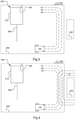
- FIG 3 shows a schematic overview of a robotic lawnmower system 200, such as that in figure 2 , in which a robotic lawnmower 100 is configured to follow a cable such as a guide cable 260 or a boundary cable 250.
- the robotic lawnmower 100 may follow the cable 250 at different distances here exemplified by three dashed lines corresponding to three different amplitude levels A1, A2 and A3.
- the inventors have realized that there are two problems with such an arrangement.
- the first problem is that over time, wheel tracks may also be formed within the corridor. Suggestions such as moving at a constantly varying distance within the corridor have been proposed to overcome this problem partially, but not fully and may also lead to difficulties in traversing between different work areas,
- the second problem is that Vietnamese at least for larger corridors .... the robotic lawnmower may lose the signal or synchronization with the signal when following the cable in a wide corridor and when there is interference or other disturbances, at which times the received control signal may not be received at a good enough quality level to successfully follow it.
- Figure 4 shows a schematic overview of a robotic lawnmower system 200, such as that in figure 2 or 3 , in which a source of disturbance or interfere-nee is shown 250',
- the source of interference may be an adjacent work area enclosed by a boundary cable 250'.
- other sources of interference may also be present, such as Radio frequency receivers or transmitters to mention but one example.
- the disturbance or interference caused by the source of interference is illustrated in figure 4 as dotted lines marked D for disturbance. It should be noted that for the purpose herein, there is not made any difference between nose, interference or other disturbances.
- the inventors have, after insightful and inspired reasoning, come up with a simple and efficient manner of solving both these problems, and also others, at the same time, without requiring any structural modifications to a robotic lawnmower.
- the solution proposed herein is to continuously or repeatedly monitor the received signal level as before, but also to determine a signal quality level.
- a signal quality level As would be apparent to a skilled reader there are many ways of measuring the signal quality, both in absolute terms and in relative terms.
- One example would be to calculate a Signal-to-Noise Ratio (SNR).
- SNR Signal-to-Noise Ratio
- the quality of a signal is not the same as the amplitude or strength of a signal, A signal may very well have a high signal strength, but still suffer from a low quality, or vice versa, namely low amplitude but a high quality.
- SNR Signal-to-Noise Ratio
- the robotic lawnmower is further configured to determine that the received signal quality is changing and in response thereto adapt the distance at which the cable is to be followed.
- the robotic lawnmower is configured to determine that the signal quality level is changing, by determining an actual change and in response thereto adapt the distance ⁇ or amplitude level - at which the cable is to be followed.
- the robotic lawnmower is alternatively or additionally configured to determine that the signal quality level is changing, by determining that the signal quality level has passed (that is the signal quality level is above or below) a threshold level and in response thereto adapt the distance - or amplitude level - at which the cable is to be followed.
- the robotic lawnmower is, in one embodiment, configured to adapt the distance- or amplitude level - at which the cable is to be followed stepwise. For example, in an implementation where several amplitude levels (A1, A2, A3) are possible and the robotic lawnmower is set to follow at a first amplitude level, say A2, the robotic lawnmower is then configured to adapt the distance by selecting a closer amplitude level, say A3, if it is determined that the interference is increasing, or to select a more remote amplitude level, say A1, if it is determined that the interference is increasing,
- the amount that the distance to be followed is adapted may be a constant step or it may be proportionate to the change in signal quality resulting in several steps.
- the robotic lawnmower is, in one embodiment, configured to adapt the distance - or amplitude level - at which the cable is to be followed proportionately to the change in signal quality level. For example, an increase of 25 % in interference may result in a decrease of the distance by 25 %.
- the amount of adaptation may not correspond exactly to the change in signal quality but may be modified by a scaling factor (25 % change would result in 12% change),
- the robotic lawnmower is, in one embodiment, configured to adapt the distance - or amplitude level - at which the cable is to be followed proportionately to the change in signal quality level relative a reference value. For example, if the received signal quality level is 3/4 of the reference signal quality level, the adapted distance is set to 4/3 of the reference distance. In one embodiment, the reference quality level is set to be the current received signal quality level.
- the reference distance/amplitude is set to be the current distf.mceiamplitude.
- Figure 5 shows a schematic overview of a robotic lawnmower system 200, such as that in figures 2 , 3 and 4 in which the robotic lawnmower 100 has adapted the distance in the vicinity of the source of interference 250', i.e. where the interference is higher.
- the robotic lawnmower 100 Starting in the direction of the robotic lawnmower 100, assumed to follow the boundary cable from the lower edge, rightwards, turning upwards to follow the right edge, and finally turning left to follow the upper edge leftwards to the charging station 210, the robotic lawnmower follows the cable at a first distance A1, A2, A3 and as the robotic lawnmower detects that the signal quality level is changed, due to the increase in interference indicted by the dotted lines D, the robotic lawnmower 100 adapts the distance A1, A2, A3 at which the robotic lawnmower follows the cable by decreasing the distance, i.e. increasing the amplitude at which the robotic lawnmower follows the cable.
- FIG. 5 This is illustrated in figure 5 by the dashed lines indicating the amplitude level ⁇ distances are drawn closer to the boundary cable.
- the robotic lawnmower is now enabled to follow the cable 250 more securely despite the interference. Subsequently, the robotic lawnmower detects or determines that the signal quality level increases, as the robotic lawnmower 100 moves away from the source of interference 250', and adapts the distance/amplitude at which the cable is followed by increasing the distance, i.e. decreasing the amplitude.
- the example of figure 5 shows a continuous or proportionate adaptation of the distance, but as has been disclosed in the above other possibilities exist and are all considered to be part of the teachings herein.
- sources of interference may be more or less static/permanent, for example a mobile phone that is sued in a garden is not always used at the same place and also not always used, this also provides for a non-static following of the border cable, in that the distance will be changed according to the changing interferences, thus the first problem is also solved by providing a manner of following the border cable that changes in a possibly unreliable manner.
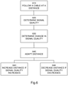
- Figure 6 shows a flowchart for a general method according to herein where the robotic lawnmower 100 is arranged for following 610 the cable (250, 260) at a distance by determining a received signal amplitude level of the received signal and steering the robotic lawnmower so that the received amplitude level corresponds (substantially equal to) to a set amplitude level.
- the robotic lawnmower determines 620 a received signal quality level and determines 630 if the received signal quality level has changed, and in response thereto adapts 640 the set amplitude level, thereby adapting the distance at which the robotic lawnmower (100) is following the cable at
- the robotic lawnmower adapts the amplitude by increasing 643 the amplitude, thereby decreasing the distance, when it is determined that the received signal quality level is decreasing, and adapts the amplitude by decreasing 646 the amplitude, thereby increasing the distance, when it is determined that the received signal quality level is increasing.
- the robotic lawnmower is configured to follow the cable at a distance set by the received signal strength and controlling the movement of the robotic lawnmower so that a (relatively) constant signal strength is maintained.
- the controller is configured to determine a received signal quality level and adapting the distance at which the robotic lawnmower is following the cable at according to the determined signal quality level by steering the robotic lawnmower so that the received signal quality level corresponds (substantially equal to) to a set signal quality level.
- the robotic lawnmower receives the magnetic field caused by the transmitted signal, determines a signal strength and compares this tie a set signal strength level. If the received signal strength is above the set signal strength, the roboti lawnmower steers away from the cable.
- the robotic lawnmower is configured to adapt the distance by adapting a corridor width associated with the distance. In doing so, the distance will also be adapted.
- the robotic lawnmower may in one embodiment, adapt the distance at substantially the same time as the corridor is adapted. The distance may then be adapted in a corresponding manner, or it may be adapted by selecting a new distance from the distances available within the corridor.
- a corridor is understood to mean a maximum distance or distance interval from the cable that the robot is to remain within while following the cable.
- the corridor may be adapted in the same manner as has been disclosed for adapting the distance.
- the signal generator 240 may be configured to adapt the amplitude of the transmitted signal and thereby changing the distance at which the robotic lawnmower follows the cable at.
Landscapes
- Engineering & Computer Science (AREA)
- Physics & Mathematics (AREA)
- Aviation & Aerospace Engineering (AREA)
- Radar, Positioning & Navigation (AREA)
- Remote Sensing (AREA)
- General Physics & Mathematics (AREA)
- Automation & Control Theory (AREA)
- Life Sciences & Earth Sciences (AREA)
- Environmental Sciences (AREA)
- Electromagnetism (AREA)
- Control Of Position, Course, Altitude, Or Attitude Of Moving Bodies (AREA)
- Harvester Elements (AREA)
Claims (17)
- Roboterrasenmähersystem, umfassend einen Roboterrasenmäher (100) und einen Signalgenerator (240), mit dem ein Kabel (250, 260) zu verbinden ist, wobei der Signalgenerator (240) ausgelegt ist zum Senden eines Signals (245) durch das Kabel (250, 260), und wobei der Roboterrasenmäher (100) Folgendes umfasst:einen Sensor (170), ausgelegt zum Aufnehmen von durch das Signal (245) im Kabel (250, 260) erzeugten Magnetfeldern, dadurch das Signal (245), das gesendet wird, empfangend, undeine Steuerung (110), ausgelegt zum Steuern des Roboterrasenmähers (100), um dem Kabel (250, 260) in einem Abstand zu folgen durch:Bestimmen eines empfangenen Signalamplitudenpegels des empfangenen Signals undLenken des Roboterrasenmähers, sodass der empfangene Amplitudenpegel einem festgelegten Amplitudenpegel entspricht bzw. vorzugsweise im Wesentlichen gleich diesem ist;dadurch gekennzeichnet, dass die Steuerung ferner ausgelegt ist zum:Bestimmen eines empfangenen Signalqualitätspegels des empfangenen Signals;Bestimmen, ob sich der empfangene Signalqualitätspegel geändert hat, und, in Reaktion darauf, Anpassen des festgelegten Amplitudenpegels, dadurch den Abstand anpassend, in dem der Roboterrasenmäher (100) entsprechend dem bestimmten Signalqualitätspegel dem Kabel folgt.
- Roboterrasenmähersystem nach Anspruch 1, wobei die Steuerung ferner dazu ausgelegt ist, den festgelegten Amplitudenpegel proportional zur Änderung im empfangenen Signalqualitätspegel anzupassen.
- Roboterrasenmähersystem nach Anspruch 1 oder 2, wobei die Steuerung ferner dazu ausgelegt ist, den festgelegten Amplitudenpegel schrittweise anzupassen.
- Roboterrasenmähersystem nach einem der Ansprüche 1 bis 3, wobei die Steuerung ferner dazu ausgelegt ist, den festgelegten Amplitudenpegel basierend auf einem Referenzamplitudenpegel anzupassen.
- Roboterrasenmähersystem nach Anspruch 4, wobei der Referenzamplitudenpegel der vorher festgelegte Amplitudenpegel ist.
- Roboterrasenmähersystem nach einem der Ansprüche 1 bis 5, wobei die Steuerung ferner ausgelegt ist zum Bestimmen, dass sich der Signalqualitätspegel geändert hat, durch Bestimmen, dass der Signalqualitätspegel einen Schwellenpegel überschritten hat.
- Roboterrasenmähersystem nach einem der Ansprüche 1 bis 5, wobei die Steuerung ferner ausgelegt ist zum Bestimmen, dass sich der Signalqualitätspegel geändert hat, durch Vergleichen des Signalqualitätspegels mit einem Referenzsignalqualitätspegel.
- Roboterrasenmähersystem nach Anspruch 7, wobei der Referenzsignalqualitätspegel der vorher bestimmte Signalqualitätspegel ist.
- Roboterrasenmähersystem nach einem der Ansprüche 1 bis 8, wobei die Steuerung ferner ausgelegt ist zum Anpassen des festgelegten Amplitudenpegels durch Erhöhen des festgelegten Amplitudenpegels, wenn bestimmt wird, dass sich der empfangene Signalqualitätspegel verringert, dadurch den Abstand verringernd, und
Anpassen des festgelegten Amplitudenpegels durch Verringern der Amplitude, wenn bestimmt wird, dass sich der empfangene Signalqualitätspegel erhöht, dadurch den Abstand vergrößernd. - Roboterrasenmähersystem nach Anspruch 1, wobei die Steuerung ferner dazu ausgelegt ist, dem Kabel (250, 260) in einem Abstand zu folgen durch Lenken des Roboterrasenmähers, sodass der empfangene Signalqualitätspegel einem festgelegten Signalqualitätspegel entspricht (bzw. im Wesentlichen gleich diesem ist).
- Roboterrasenmähersystem nach einem der vorhergehenden Ansprüche, wobei die Steuerung ferner dazu ausgelegt ist, den Abstand durch Anpassen eines Korridors anzupassen.
- Roboterrasenmähersystem nach Anspruch 11, wobei die Steuerung ferner dazu ausgelegt ist, den Abstand im Wesentlichen zur gleichen Zeit wie das Anpassen des Korridors anzupassen.
- Roboterrasenmähersystem nach Anspruch 12, wobei die Steuerung ferner dazu ausgelegt ist, den Abstand durch Auswählen eines neuen Abstands innerhalb des angepassten Korridors anzupassen.
- Roboterrasenmähersystem nach einem der vorhergehenden Ansprüche, wobei der Signalgenerator (240) dazu ausgelegt ist, die Amplitude des gesendeten Signals anzupassen und dadurch den Abstand zu ändern, in dem der Roboterrasenmäher (100) dem Kabel (250, 260) folgt.
- Roboterrasenmähersystem nach einem der vorhergehenden Ansprüche, wobei das Kabel ein Begrenzungskabel (250) ist.
- Verfahren zur Verwendung in einem Roboterrasenmähersystem, umfassend einen Roboterrasenmäher (100) und einen Signalgenerator (240), mit dem ein Kabel (250, 260) zu verbinden ist, wobei der Signalgenerator (240) ausgelegt ist zum Senden eines Signals (245) durch das Kabel (250, 260), und wobei der Roboterrasenmäher (100) Folgendes umfasst:einen Sensor (170), ausgelegt zum Aufnehmen von durch das Signal (245) im Kabel (250, 260) erzeugten Magnetfeldern, dadurch das Signal (245), das gesendet wird, empfangend, wobei das Verfahren Folgendes umfasst: Folgen, durch den Roboterrasenmäher (100), dem Kabel (250, 260) in einem Abstand durch:Bestimmen eines empfangenen Signalamplitudenpegels des empfangenen Signals undLenken des Roboterrasenmähers, sodass der empfangene Amplitudenpegel dem festgelegten Amplitudenpegel entspricht bzw. vorzugsweise im Wesentlichen gleich diesem ist,dadurch gekennzeichnet, dass das Verfahren ferner Folgendes umfasst:Bestimmen eines empfangenen Signalqualitätspegels des empfangenen Signals;Bestimmen, ob sich der empfangene Signalqualitätspegel geändert hat, und, in Reaktion darauf, Anpassen des festgelegten Amplitudenpegels, dadurch den Abstand anpassend, in dem der Roboterrasenmäher (100) entsprechend dem bestimmten Signalqualitätspegel dem Kabel folgt.
- Verfahren nach Anspruch 16, wobei das Verfahren ferner umfasst, dem Kabel (250, 260) in einem Abstand zu folgen durch Lenken des Roboterrasenmähers, sodass der empfangene Signalqualitätspegel einem festgelegten Signalqualitätspegel entspricht bzw. vorzugsweise im Wesentlichen gleich diesem ist.
Applications Claiming Priority (2)
| Application Number | Priority Date | Filing Date | Title |
|---|---|---|---|
| SE1750226A SE540605C2 (en) | 2017-03-02 | 2017-03-02 | Improved reduction of wheel tracks for robotic lawnmower |
| PCT/SE2018/050051 WO2018160114A1 (en) | 2017-03-02 | 2018-01-24 | Improved reduction of wheel tracks for robotic lawnmower |
Publications (3)
| Publication Number | Publication Date |
|---|---|
| EP3589111A1 EP3589111A1 (de) | 2020-01-08 |
| EP3589111A4 EP3589111A4 (de) | 2020-12-02 |
| EP3589111B1 true EP3589111B1 (de) | 2022-02-09 |
Family
ID=63370950
Family Applications (1)
| Application Number | Title | Priority Date | Filing Date |
|---|---|---|---|
| EP18761934.1A Active EP3589111B1 (de) | 2017-03-02 | 2018-01-24 | Verbesserte reduzierung von radspuren für roboterrasenmäher |
Country Status (5)
| Country | Link |
|---|---|
| US (1) | US11310957B2 (de) |
| EP (1) | EP3589111B1 (de) |
| CN (1) | CN110392523B (de) |
| SE (1) | SE540605C2 (de) |
| WO (1) | WO2018160114A1 (de) |
Cited By (1)
| Publication number | Priority date | Publication date | Assignee | Title |
|---|---|---|---|---|
| US20240264609A1 (en) * | 2023-02-03 | 2024-08-08 | Computime Limited | Random Pattern Mowing |
Families Citing this family (19)
| Publication number | Priority date | Publication date | Assignee | Title |
|---|---|---|---|---|
| US11172608B2 (en) | 2016-06-30 | 2021-11-16 | Tti (Macao Commercial Offshore) Limited | Autonomous lawn mower and a system for navigating thereof |
| US11172605B2 (en) | 2016-06-30 | 2021-11-16 | Tti (Macao Commercial Offshore) Limited | Autonomous lawn mower and a system for navigating thereof |
| SE544288C2 (en) * | 2019-09-30 | 2022-03-29 | Husqvarna Ab | Robotic work tool system and method for transporting a robotic work tool between different areas |
| SE543950C2 (en) * | 2019-12-04 | 2021-10-05 | Husqvarna Ab | Robotic work tool being configured to switch between at least two offset settings |
| WO2021208010A1 (en) * | 2020-04-16 | 2021-10-21 | Globe (jiangsu) Co., Ltd. | Navigating a robotic mower along a guide wire |
| EP4147555B1 (de) * | 2020-06-03 | 2024-11-20 | Globe (Jiangsu) Co., Ltd. | Automatischer rasenmäher und wegplanungsverfahren, system und vorrichtung dafür |
| CN116600635B (zh) | 2020-12-25 | 2025-09-16 | 格力博(江苏)股份有限公司 | 通过导线导航机器人割草机 |
| CN114788451B (zh) * | 2021-01-25 | 2024-04-30 | 南京泉峰科技有限公司 | 智能割草机系统及其充电站 |
| US12296694B2 (en) | 2021-03-10 | 2025-05-13 | Techtronic Cordless Gp | Lawnmowers |
| CN115211273B (zh) * | 2021-04-15 | 2024-04-19 | 浙江亚特电器股份有限公司 | 一种割草机导航方法、装置、设备及无人割草系统 |
| US12443180B2 (en) | 2021-11-10 | 2025-10-14 | Techtronic Cordless Gp | Robotic lawn mowers |
| US12510891B2 (en) * | 2021-11-30 | 2025-12-30 | Honda Motor Co., Ltd. | Travel route control of autonomous work vehicle to reduce travel distance |
| AU2023200381A1 (en) | 2022-01-31 | 2023-08-17 | Techtronic Cordless Gp | Robotic garden tool |
| EP4270138A1 (de) | 2022-04-28 | 2023-11-01 | Techtronic Cordless GP | Erzeugung einer virtuellen grenze für ein robotisches gartenwerkzeug |
| SE547975C2 (en) * | 2022-05-09 | 2026-01-02 | Husqvarna Ab | Cost-efficient navigation for robotic work tool system by trial and error learning of work area |
| US12472611B2 (en) | 2022-05-31 | 2025-11-18 | Techtronic Cordless Gp | Peg driver |
| AU2023204696A1 (en) | 2022-07-19 | 2024-02-08 | Techtronic Cordless Gp | Display for controlling robotic tool |
| EP4340296B1 (de) | 2022-07-29 | 2025-04-09 | Techtronic Cordless GP | Erzeugung eines kryptoschlüssels für ein robotisches gartenwerkzeug |
| CN118892020A (zh) * | 2023-04-28 | 2024-11-05 | 深圳乐动机器人股份有限公司 | 一种草坪的拐弯区域的割草控制方法及割草机器人系统 |
Family Cites Families (19)
| Publication number | Priority date | Publication date | Assignee | Title |
|---|---|---|---|---|
| SE0201739D0 (sv) | 2002-06-07 | 2002-06-07 | Electrolux Ab | Elektroniskt avgränsningssystem |
| SE0201740D0 (sv) * | 2002-06-07 | 2002-06-07 | Electrolux Ab | Electroniskt diregeringssystem |
| WO2011129728A1 (en) * | 2010-04-14 | 2011-10-20 | Husqvarna Ab | Robotic garden tool following wires at a distance using multiple signals |
| US8352113B2 (en) * | 2010-07-28 | 2013-01-08 | Deere & Company | Robotic mower boundary coverage system |
| US8392044B2 (en) * | 2010-07-28 | 2013-03-05 | Deere & Company | Robotic mower boundary sensing system |
| US9405294B2 (en) * | 2010-10-01 | 2016-08-02 | Husqvarna Ab | Method and system for guiding a robotic garden tool |
| US8789563B2 (en) * | 2010-10-12 | 2014-07-29 | Deere & Company | Intelligent grain bag loader |
| CN103197672A (zh) | 2012-01-05 | 2013-07-10 | 苏州宝时得电动工具有限公司 | 边界信号识别方法及其边界系统 |
| CN103838238B (zh) * | 2012-11-23 | 2017-08-01 | 苏州宝时得电动工具有限公司 | 自动工作系统 |
| EP2741160B1 (de) * | 2012-12-07 | 2016-10-12 | Viking GmbH | Verfahren zur Steuerung eines selbstfahrenden Rasenmähers |
| CN103891464B (zh) * | 2012-12-28 | 2016-08-17 | 苏州宝时得电动工具有限公司 | 自动割草系统 |
| WO2014129941A1 (en) * | 2013-02-20 | 2014-08-28 | Husqvarna Ab | A robotic work tool configured for improved turning in a slope, a robotic work tool system, and a method for use in the robot work tool. |
| EP2959350B1 (de) | 2013-02-20 | 2018-04-04 | Husqvarna AB | Verfahren und robotisches arbeitswerkzeugsystem mit einer ladestation und einem begrenzungsdraht |
| US9713303B2 (en) * | 2013-02-21 | 2017-07-25 | Husqvarna Ab | Robotic working tool |
| EP3100126B1 (de) | 2014-01-30 | 2018-12-05 | Husqvarna AB | Robotische arbeitsvorrichtung mit einem grenzdraht |
| CN104977929B (zh) * | 2014-04-09 | 2019-04-12 | 燕成祥 | 导引式清洁装置与导引式清洁组 |
| SE1451645A1 (sv) * | 2014-12-23 | 2016-05-31 | Husqvarna Ab | Improved navigation for a robotic lawnmower |
| CN104699101A (zh) * | 2015-01-30 | 2015-06-10 | 深圳拓邦股份有限公司 | 可定制割草区域的机器人割草系统及其控制方法 |
| JP6014182B2 (ja) * | 2015-02-10 | 2016-10-25 | 本田技研工業株式会社 | 自律走行作業車の制御装置 |
-
2017
- 2017-03-02 SE SE1750226A patent/SE540605C2/en not_active IP Right Cessation
-
2018
- 2018-01-24 US US16/489,863 patent/US11310957B2/en active Active
- 2018-01-24 WO PCT/SE2018/050051 patent/WO2018160114A1/en not_active Ceased
- 2018-01-24 CN CN201880015345.0A patent/CN110392523B/zh active Active
- 2018-01-24 EP EP18761934.1A patent/EP3589111B1/de active Active
Cited By (2)
| Publication number | Priority date | Publication date | Assignee | Title |
|---|---|---|---|---|
| US20240264609A1 (en) * | 2023-02-03 | 2024-08-08 | Computime Limited | Random Pattern Mowing |
| US12547188B2 (en) * | 2023-02-03 | 2026-02-10 | Computime Limited | Random pattern mowing |
Also Published As
| Publication number | Publication date |
|---|---|
| SE1750226A1 (sv) | 2018-09-03 |
| WO2018160114A1 (en) | 2018-09-07 |
| CN110392523B (zh) | 2022-04-12 |
| US11310957B2 (en) | 2022-04-26 |
| EP3589111A1 (de) | 2020-01-08 |
| EP3589111A4 (de) | 2020-12-02 |
| SE540605C2 (en) | 2018-10-02 |
| CN110392523A (zh) | 2019-10-29 |
| US20190380266A1 (en) | 2019-12-19 |
Similar Documents
| Publication | Publication Date | Title |
|---|---|---|
| EP3589111B1 (de) | Verbesserte reduzierung von radspuren für roboterrasenmäher | |
| EP3161571B1 (de) | Verbessertes robotisches arbeitswerkzeug | |
| US11974519B2 (en) | System and method for navigating a robotic lawnmower into a docketing position | |
| EP3444565B1 (de) | Vorrichtung mit automatischer bewegung für automatisches arbeitssystem und steuerungsverfahren dafür | |
| EP2959351B1 (de) | Verbessertes robotisches arbeitswerkzeug | |
| US12197203B2 (en) | Exit path determination for a robotic work tool | |
| US7574282B2 (en) | Electronic directing system | |
| US10928833B2 (en) | Navigation for a robotic work tool | |
| EP2806325B1 (de) | Hausrobotersystem | |
| EP3616021B1 (de) | Adaptive signalsynchronisation in einem robotischen rasenmähersystem | |
| US10222797B2 (en) | Control apparatus for autonomously navigating utility vehicle | |
| CN107608341A (zh) | 自动工作系统及自移动园艺设备的回归控制方法 | |
| CN110018686A (zh) | 一种智能割草机的路径规划方法 | |
| EP3069204A1 (de) | Verbesserte navigation für ein robotisches arbeitswerkzeug | |
| US20230112518A1 (en) | Working robot and control method | |
| CN117315038A (zh) | 异常区域标定方法及相关装置 |
Legal Events
| Date | Code | Title | Description |
|---|---|---|---|
| STAA | Information on the status of an ep patent application or granted ep patent |
Free format text: STATUS: THE INTERNATIONAL PUBLICATION HAS BEEN MADE |
|
| PUAI | Public reference made under article 153(3) epc to a published international application that has entered the european phase |
Free format text: ORIGINAL CODE: 0009012 |
|
| STAA | Information on the status of an ep patent application or granted ep patent |
Free format text: STATUS: REQUEST FOR EXAMINATION WAS MADE |
|
| 17P | Request for examination filed |
Effective date: 20190904 |
|
| AK | Designated contracting states |
Kind code of ref document: A1 Designated state(s): AL AT BE BG CH CY CZ DE DK EE ES FI FR GB GR HR HU IE IS IT LI LT LU LV MC MK MT NL NO PL PT RO RS SE SI SK SM TR |
|
| AX | Request for extension of the european patent |
Extension state: BA ME |
|
| DAV | Request for validation of the european patent (deleted) | ||
| DAX | Request for extension of the european patent (deleted) | ||
| REG | Reference to a national code |
Ref country code: DE Ref legal event code: R079 Ref document number: 602018030599 Country of ref document: DE Free format text: PREVIOUS MAIN CLASS: A01D0034000000 Ipc: G05D0001020000 |
|
| A4 | Supplementary search report drawn up and despatched |
Effective date: 20201103 |
|
| RIC1 | Information provided on ipc code assigned before grant |
Ipc: A01D 34/00 20060101ALI20201028BHEP Ipc: G05D 1/02 20200101AFI20201028BHEP |
|
| GRAP | Despatch of communication of intention to grant a patent |
Free format text: ORIGINAL CODE: EPIDOSNIGR1 |
|
| STAA | Information on the status of an ep patent application or granted ep patent |
Free format text: STATUS: GRANT OF PATENT IS INTENDED |
|
| INTG | Intention to grant announced |
Effective date: 20210910 |
|
| GRAS | Grant fee paid |
Free format text: ORIGINAL CODE: EPIDOSNIGR3 |
|
| GRAA | (expected) grant |
Free format text: ORIGINAL CODE: 0009210 |
|
| STAA | Information on the status of an ep patent application or granted ep patent |
Free format text: STATUS: THE PATENT HAS BEEN GRANTED |
|
| AK | Designated contracting states |
Kind code of ref document: B1 Designated state(s): AL AT BE BG CH CY CZ DE DK EE ES FI FR GB GR HR HU IE IS IT LI LT LU LV MC MK MT NL NO PL PT RO RS SE SI SK SM TR |
|
| REG | Reference to a national code |
Ref country code: GB Ref legal event code: FG4D |
|
| REG | Reference to a national code |
Ref country code: CH Ref legal event code: EP Ref country code: AT Ref legal event code: REF Ref document number: 1467898 Country of ref document: AT Kind code of ref document: T Effective date: 20220215 |
|
| REG | Reference to a national code |
Ref country code: IE Ref legal event code: FG4D |
|
| REG | Reference to a national code |
Ref country code: DE Ref legal event code: R096 Ref document number: 602018030599 Country of ref document: DE |
|
| REG | Reference to a national code |
Ref country code: LT Ref legal event code: MG9D |
|
| REG | Reference to a national code |
Ref country code: NL Ref legal event code: MP Effective date: 20220209 |
|
| REG | Reference to a national code |
Ref country code: AT Ref legal event code: MK05 Ref document number: 1467898 Country of ref document: AT Kind code of ref document: T Effective date: 20220209 |
|
| PG25 | Lapsed in a contracting state [announced via postgrant information from national office to epo] |
Ref country code: SE Free format text: LAPSE BECAUSE OF FAILURE TO SUBMIT A TRANSLATION OF THE DESCRIPTION OR TO PAY THE FEE WITHIN THE PRESCRIBED TIME-LIMIT Effective date: 20220209 Ref country code: RS Free format text: LAPSE BECAUSE OF FAILURE TO SUBMIT A TRANSLATION OF THE DESCRIPTION OR TO PAY THE FEE WITHIN THE PRESCRIBED TIME-LIMIT Effective date: 20220209 Ref country code: PT Free format text: LAPSE BECAUSE OF FAILURE TO SUBMIT A TRANSLATION OF THE DESCRIPTION OR TO PAY THE FEE WITHIN THE PRESCRIBED TIME-LIMIT Effective date: 20220609 Ref country code: NO Free format text: LAPSE BECAUSE OF FAILURE TO SUBMIT A TRANSLATION OF THE DESCRIPTION OR TO PAY THE FEE WITHIN THE PRESCRIBED TIME-LIMIT Effective date: 20220509 Ref country code: NL Free format text: LAPSE BECAUSE OF FAILURE TO SUBMIT A TRANSLATION OF THE DESCRIPTION OR TO PAY THE FEE WITHIN THE PRESCRIBED TIME-LIMIT Effective date: 20220209 Ref country code: LT Free format text: LAPSE BECAUSE OF FAILURE TO SUBMIT A TRANSLATION OF THE DESCRIPTION OR TO PAY THE FEE WITHIN THE PRESCRIBED TIME-LIMIT Effective date: 20220209 Ref country code: HR Free format text: LAPSE BECAUSE OF FAILURE TO SUBMIT A TRANSLATION OF THE DESCRIPTION OR TO PAY THE FEE WITHIN THE PRESCRIBED TIME-LIMIT Effective date: 20220209 Ref country code: ES Free format text: LAPSE BECAUSE OF FAILURE TO SUBMIT A TRANSLATION OF THE DESCRIPTION OR TO PAY THE FEE WITHIN THE PRESCRIBED TIME-LIMIT Effective date: 20220209 Ref country code: BG Free format text: LAPSE BECAUSE OF FAILURE TO SUBMIT A TRANSLATION OF THE DESCRIPTION OR TO PAY THE FEE WITHIN THE PRESCRIBED TIME-LIMIT Effective date: 20220509 |
|
| PG25 | Lapsed in a contracting state [announced via postgrant information from national office to epo] |
Ref country code: PL Free format text: LAPSE BECAUSE OF FAILURE TO SUBMIT A TRANSLATION OF THE DESCRIPTION OR TO PAY THE FEE WITHIN THE PRESCRIBED TIME-LIMIT Effective date: 20220209 Ref country code: LV Free format text: LAPSE BECAUSE OF FAILURE TO SUBMIT A TRANSLATION OF THE DESCRIPTION OR TO PAY THE FEE WITHIN THE PRESCRIBED TIME-LIMIT Effective date: 20220209 Ref country code: GR Free format text: LAPSE BECAUSE OF FAILURE TO SUBMIT A TRANSLATION OF THE DESCRIPTION OR TO PAY THE FEE WITHIN THE PRESCRIBED TIME-LIMIT Effective date: 20220510 Ref country code: FI Free format text: LAPSE BECAUSE OF FAILURE TO SUBMIT A TRANSLATION OF THE DESCRIPTION OR TO PAY THE FEE WITHIN THE PRESCRIBED TIME-LIMIT Effective date: 20220209 Ref country code: AT Free format text: LAPSE BECAUSE OF FAILURE TO SUBMIT A TRANSLATION OF THE DESCRIPTION OR TO PAY THE FEE WITHIN THE PRESCRIBED TIME-LIMIT Effective date: 20220209 |
|
| PG25 | Lapsed in a contracting state [announced via postgrant information from national office to epo] |
Ref country code: IS Free format text: LAPSE BECAUSE OF FAILURE TO SUBMIT A TRANSLATION OF THE DESCRIPTION OR TO PAY THE FEE WITHIN THE PRESCRIBED TIME-LIMIT Effective date: 20220609 |
|
| PG25 | Lapsed in a contracting state [announced via postgrant information from national office to epo] |
Ref country code: SM Free format text: LAPSE BECAUSE OF FAILURE TO SUBMIT A TRANSLATION OF THE DESCRIPTION OR TO PAY THE FEE WITHIN THE PRESCRIBED TIME-LIMIT Effective date: 20220209 Ref country code: SK Free format text: LAPSE BECAUSE OF FAILURE TO SUBMIT A TRANSLATION OF THE DESCRIPTION OR TO PAY THE FEE WITHIN THE PRESCRIBED TIME-LIMIT Effective date: 20220209 Ref country code: RO Free format text: LAPSE BECAUSE OF FAILURE TO SUBMIT A TRANSLATION OF THE DESCRIPTION OR TO PAY THE FEE WITHIN THE PRESCRIBED TIME-LIMIT Effective date: 20220209 Ref country code: EE Free format text: LAPSE BECAUSE OF FAILURE TO SUBMIT A TRANSLATION OF THE DESCRIPTION OR TO PAY THE FEE WITHIN THE PRESCRIBED TIME-LIMIT Effective date: 20220209 Ref country code: DK Free format text: LAPSE BECAUSE OF FAILURE TO SUBMIT A TRANSLATION OF THE DESCRIPTION OR TO PAY THE FEE WITHIN THE PRESCRIBED TIME-LIMIT Effective date: 20220209 Ref country code: CZ Free format text: LAPSE BECAUSE OF FAILURE TO SUBMIT A TRANSLATION OF THE DESCRIPTION OR TO PAY THE FEE WITHIN THE PRESCRIBED TIME-LIMIT Effective date: 20220209 |
|
| REG | Reference to a national code |
Ref country code: DE Ref legal event code: R097 Ref document number: 602018030599 Country of ref document: DE |
|
| PG25 | Lapsed in a contracting state [announced via postgrant information from national office to epo] |
Ref country code: AL Free format text: LAPSE BECAUSE OF FAILURE TO SUBMIT A TRANSLATION OF THE DESCRIPTION OR TO PAY THE FEE WITHIN THE PRESCRIBED TIME-LIMIT Effective date: 20220209 |
|
| PLBE | No opposition filed within time limit |
Free format text: ORIGINAL CODE: 0009261 |
|
| STAA | Information on the status of an ep patent application or granted ep patent |
Free format text: STATUS: NO OPPOSITION FILED WITHIN TIME LIMIT |
|
| 26N | No opposition filed |
Effective date: 20221110 |
|
| PG25 | Lapsed in a contracting state [announced via postgrant information from national office to epo] |
Ref country code: SI Free format text: LAPSE BECAUSE OF FAILURE TO SUBMIT A TRANSLATION OF THE DESCRIPTION OR TO PAY THE FEE WITHIN THE PRESCRIBED TIME-LIMIT Effective date: 20220209 |
|
| P01 | Opt-out of the competence of the unified patent court (upc) registered |
Effective date: 20230419 |
|
| PG25 | Lapsed in a contracting state [announced via postgrant information from national office to epo] |
Ref country code: IT Free format text: LAPSE BECAUSE OF FAILURE TO SUBMIT A TRANSLATION OF THE DESCRIPTION OR TO PAY THE FEE WITHIN THE PRESCRIBED TIME-LIMIT Effective date: 20220209 |
|
| PG25 | Lapsed in a contracting state [announced via postgrant information from national office to epo] |
Ref country code: LU Free format text: LAPSE BECAUSE OF NON-PAYMENT OF DUE FEES Effective date: 20230124 |
|
| REG | Reference to a national code |
Ref country code: BE Ref legal event code: MM Effective date: 20230131 |
|
| REG | Reference to a national code |
Ref country code: DE Ref legal event code: R079 Ref document number: 602018030599 Country of ref document: DE Free format text: PREVIOUS MAIN CLASS: G05D0001020000 Ipc: G05D0001430000 |
|
| PG25 | Lapsed in a contracting state [announced via postgrant information from national office to epo] |
Ref country code: BE Free format text: LAPSE BECAUSE OF NON-PAYMENT OF DUE FEES Effective date: 20230131 |
|
| PGFP | Annual fee paid to national office [announced via postgrant information from national office to epo] |
Ref country code: GB Payment date: 20231222 Year of fee payment: 7 |
|
| PG25 | Lapsed in a contracting state [announced via postgrant information from national office to epo] |
Ref country code: IE Free format text: LAPSE BECAUSE OF NON-PAYMENT OF DUE FEES Effective date: 20230124 |
|
| PGFP | Annual fee paid to national office [announced via postgrant information from national office to epo] |
Ref country code: CH Payment date: 20240202 Year of fee payment: 7 |
|
| PG25 | Lapsed in a contracting state [announced via postgrant information from national office to epo] |
Ref country code: MC Free format text: LAPSE BECAUSE OF FAILURE TO SUBMIT A TRANSLATION OF THE DESCRIPTION OR TO PAY THE FEE WITHIN THE PRESCRIBED TIME-LIMIT Effective date: 20220209 |
|
| PG25 | Lapsed in a contracting state [announced via postgrant information from national office to epo] |
Ref country code: MC Free format text: LAPSE BECAUSE OF FAILURE TO SUBMIT A TRANSLATION OF THE DESCRIPTION OR TO PAY THE FEE WITHIN THE PRESCRIBED TIME-LIMIT Effective date: 20220209 |
|
| PGFP | Annual fee paid to national office [announced via postgrant information from national office to epo] |
Ref country code: FR Payment date: 20241205 Year of fee payment: 8 |
|
| PGFP | Annual fee paid to national office [announced via postgrant information from national office to epo] |
Ref country code: DE Payment date: 20241216 Year of fee payment: 8 |
|
| PG25 | Lapsed in a contracting state [announced via postgrant information from national office to epo] |
Ref country code: CY Free format text: LAPSE BECAUSE OF FAILURE TO SUBMIT A TRANSLATION OF THE DESCRIPTION OR TO PAY THE FEE WITHIN THE PRESCRIBED TIME-LIMIT; INVALID AB INITIO Effective date: 20180124 |
|
| PG25 | Lapsed in a contracting state [announced via postgrant information from national office to epo] |
Ref country code: HU Free format text: LAPSE BECAUSE OF FAILURE TO SUBMIT A TRANSLATION OF THE DESCRIPTION OR TO PAY THE FEE WITHIN THE PRESCRIBED TIME-LIMIT; INVALID AB INITIO Effective date: 20180124 |
|
| REG | Reference to a national code |
Ref country code: CH Ref legal event code: PL |
|
| GBPC | Gb: european patent ceased through non-payment of renewal fee |
Effective date: 20250124 |
|
| PG25 | Lapsed in a contracting state [announced via postgrant information from national office to epo] |
Ref country code: GB Free format text: LAPSE BECAUSE OF NON-PAYMENT OF DUE FEES Effective date: 20250124 |
|
| PG25 | Lapsed in a contracting state [announced via postgrant information from national office to epo] |
Ref country code: CH Free format text: LAPSE BECAUSE OF NON-PAYMENT OF DUE FEES Effective date: 20250131 |
|
| PG25 | Lapsed in a contracting state [announced via postgrant information from national office to epo] |
Ref country code: TR Free format text: LAPSE BECAUSE OF FAILURE TO SUBMIT A TRANSLATION OF THE DESCRIPTION OR TO PAY THE FEE WITHIN THE PRESCRIBED TIME-LIMIT Effective date: 20220209 |