EP3589112B1 - System and method for determining bale location and orientation - Google Patents
System and method for determining bale location and orientation Download PDFInfo
- Publication number
- EP3589112B1 EP3589112B1 EP18709764.7A EP18709764A EP3589112B1 EP 3589112 B1 EP3589112 B1 EP 3589112B1 EP 18709764 A EP18709764 A EP 18709764A EP 3589112 B1 EP3589112 B1 EP 3589112B1
- Authority
- EP
- European Patent Office
- Prior art keywords
- bale
- orientation
- location
- computing devices
- determining
- Prior art date
- Legal status (The legal status is an assumption and is not a legal conclusion. Google has not performed a legal analysis and makes no representation as to the accuracy of the status listed.)
- Active
Links
Images






Classifications
-
- A—HUMAN NECESSITIES
- A01—AGRICULTURE; FORESTRY; ANIMAL HUSBANDRY; HUNTING; TRAPPING; FISHING
- A01F—PROCESSING OF HARVESTED PRODUCE; HAY OR STRAW PRESSES; DEVICES FOR STORING AGRICULTURAL OR HORTICULTURAL PRODUCE
- A01F15/00—Baling presses for straw, hay or the like
- A01F15/08—Details
- A01F15/0875—Discharge devices
-
- A—HUMAN NECESSITIES
- A01—AGRICULTURE; FORESTRY; ANIMAL HUSBANDRY; HUNTING; TRAPPING; FISHING
- A01F—PROCESSING OF HARVESTED PRODUCE; HAY OR STRAW PRESSES; DEVICES FOR STORING AGRICULTURAL OR HORTICULTURAL PRODUCE
- A01F15/00—Baling presses for straw, hay or the like
- A01F15/08—Details
-
- G—PHYSICS
- G01—MEASURING; TESTING
- G01S—RADIO DIRECTION-FINDING; RADIO NAVIGATION; DETERMINING DISTANCE OR VELOCITY BY USE OF RADIO WAVES; LOCATING OR PRESENCE-DETECTING BY USE OF THE REFLECTION OR RERADIATION OF RADIO WAVES; ANALOGOUS ARRANGEMENTS USING OTHER WAVES
- G01S19/00—Satellite radio beacon positioning systems; Determining position, velocity or attitude using signals transmitted by such systems
- G01S19/01—Satellite radio beacon positioning systems transmitting time-stamped messages, e.g. GPS [Global Positioning System], GLONASS [Global Orbiting Navigation Satellite System] or GALILEO
- G01S19/13—Receivers
- G01S19/14—Receivers specially adapted for specific applications
Definitions
- the present invention relates to systems and methods for determining the orientation of a bale of agricultural product formed by a mobile baling mechanism and deposited on a ground surface.
- Hay and forage crops may be harvested by cutting the crops, allowing the crops to lie on the ground to dry, and then baling the dried crop. Baling the dried crop involves the use of balers that collect the crop from the ground as the baler travels along the ground, form the crop into a bale, tie or wrap the bale to preserve the bale's shape and/or protect it from the elements, and then place the bale onto the ground.
- the bales are placed on the ground as they are formed by the baler such that a plurality of bales are placed randomly across a field.
- the bales are typically removed from the field shortly after baling and may be stacked in a convenient location in the field or in the same region, or may be transported to a distant location.
- United States patent application US 2014/278083 describes a system comprising a mobile baling mechanism for creating a bale of agricultural product and placing the bale on a ground surface, and one or more computing devices for automatically determining a location and an orientation of the bale on the ground surface.
- EP 3 254 554 discloses one or more computing devices configured to determine the orientation of a bale.
- references to “one embodiment”, “an embodiment”, or “embodiments” mean that the feature or features being referred to are included in at least one embodiment of the technology.
- references to “one embodiment”, “an embodiment”, or “embodiments” in this description do not necessarily refer to the same embodiment and are also not mutually exclusive unless so stated and/or except as will be readily apparent to those skilled in the art from the description.
- a feature, structure, act, etc. described in one embodiment may also be included in other embodiments, but is not necessarily included.
- the present technology can include a variety of combinations and/or integrations of the embodiments described herein.
- Embodiments of the invention involve a mobile baling mechanism for creating a bale of agricultural product and placing the bale on a ground surface, and a system for automatically determining a location and an orientation of the bale on the ground surface.
- the location of the bale may be defined by longitude and latitude coordinates of the bale.
- the orientation of the bale is the position of a horizontal axis of the bale about a vertical axis of the bale, such as the position of a horizontal axis of the bale relative to a cardinal direction.
- the invention may be used to collect and store location and orientation information for a plurality of bales in a field, and the information may be used to optimize collection of the plurality of bales.
- bales of agricultural product are illustrated in Figures 1 through 3 .
- Such bales may include a hay or forage crop for feeding livestock or may include straw or other biomass used for purposes other than feeding livestock.
- Round bales 10 are illustrated in Fig. 1 and rectangular bales 12 are illustrated in Figs. 2 and 3 .
- the round bales 10 are generally cylindrical in shape with opposing flat end faces 14 defining a height of the bale and a cylindrical outer surface 16 defining a width of the bale between the end faces 14.
- Round bales typically range in size from one meter in height and one meter in width to two meters in height and two meters in width.
- the weight of such bales typically falls within the range of 180 kilograms to 780 kilograms depending on the size and density of the bale.
- Some common bale sizes include 1.3 meters wide by 1.5 meters high, 1.5 meters wide by 1.5 meters high, and 1.5 meters wide by 1.8 meters high.
- Some common bale weights include 270 kilograms, 360 kilograms, 450
- bales 12 illustrated in Figs. 2 and 3 are large rectangular bales.
- Common sizes of large rectangular bales include 0.9 meters wide by 0.9 meters tall, 0.9 meters wide by 1.2 meters tall, and 1.2 meters wide by 1.2 meters tall.
- the length of large rectangular bales varies but is typically within the range of about 1.5 meters to about 2.5 meters, 1.8 meters is a common length.
- the weight of large rectangular bales typically falls within the range of 200 kilograms to 900 kilograms depending on the size and density of the bale.
- Some common bale weights include 360 kilograms, 450 kilograms, 550 kilograms and 640 kilograms.
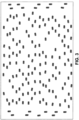
- a field may include a large number of bales, as illustrated in Fig. 3 .
- Each of the bales is placed on the ground by a mobile baling mechanism as the bale is formed such that the location and orientation of each bale is random.
- the field of Fig. 3 is depicted in plan view such that changes in elevation across the field are not discernable, but areas of ground surface that are not level would cause the bales to be tilted along a longitudinal axis (pitch), along a lateral axis (roll), or both.
- a mobile baling mechanism includes a tractor 18 coupled with a large square baler 20 as illustrated in Fig. 4 .
- the tractor 18 pulls the baler 20 through a field and drives operation of the baler 20 via a power takeoff of the tractor 18.
- a bale feeding system of the baler includes a pickup 22 for collecting hay or other agricultural product from a ground surface and feeding the agricultural product into an internal bale forming system of the baler.
- the baler forms the hay into a bale, ties the bale, and discharges the formed bale onto the ground via a chute 24 for conveying the bale to the ground surface.
- the baler 20 may include a weighing mechanism for determining a weight of the bale, and may include a sensor for determining when a bale has been deposited on the ground surface, as explained in greater detail below.
- the tractor 18, the baler 20, or both may include a control and communications system.
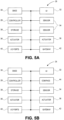
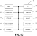
- Various components of an exemplary control and communications system 26 are illustrated in Figs. 5A-C .
- the system 26 broadly includes a controller 28, a position determining device 30, a user interface 32, one or more sensors 34, one or more actuators 36, one or more data storage components 38, one or more input/output ports 40 and a communications gateway 42.
- the position determining device 30 may include a global navigation satellite system (GNSS) receiver, such as a device configured to receive signals from one or more positioning systems such as the United States' global positioning system (GPS), the European GALILEO system and/or the Russian GLONASS system, and to determine a location of the machine using the received signals.
- GNSS global navigation satellite system
- the user interface 32 includes components for receiving instructions or other input from a user and may include buttons, switches, dials, and microphones, as well as components for presenting information or data to users, such as displays, light-emitting diodes, audio speakers and so forth.
- the user interface 32 may include a touchscreen display capable of presenting visual representations of information or data and receiving instructions or input from the user via a single display surface.
- the sensors 34 may be associated with any of various components or functions of the host machine including, for example, various elements of the engine, transmission(s), and hydraulic and electrical systems.
- One or more of the sensors 34 may be configured and placed to detect environmental or ambient conditions in, around or near the host machine.
- One of the sensors may be a compass 44, as illustrated in Fig. 5B , used to detect a heading of the machine.
- Another of the sensors may be an inclinometer 46 for detecting pitch and roll of the machine.
- the system illustrated in Fig. 5C includes both a compass 44 and an inclinometer 46.
- the actuators 36 are configured and placed to drive certain functions of the machine including, for example, steering when an automated guidance function is engaged.
- the actuators 36 may take virtually any form but are generally configured to receive control signals or instructions from the controller 28 (or other component of the system 26) and to generate a mechanical movement or action in response to the control signals or instructions.
- the sensors 34 and actuators 36 may be used in automated steering of a machine wherein the sensors 34 detect a current position or state of steered wheels or tracks and the actuators 36 drive steering action or operation of the wheels or tracks.
- the controller 28 includes one or more integrated circuits programmed or configured to implement the functions described herein.
- the controller 28 may be a digital controller and may include one or more general purpose microprocessors or microcontrollers, programmable logic devices, or application specific integrated circuits.
- the controller 28 may include multiple computing components placed in various different locations on the machine.
- the controller 28 may also include one or more discrete and/or analog circuit components operating in conjunction with the one or more integrated circuits or computing components.
- the controller 28 may include or have access to one or more memory elements operable to store executable instructions, data, or both.
- the storage device 38 stores data and preferably includes a non-volatile storage medium such as optic, magnetic or solid state technology.
- all of the components of the system 26 are contained on or in a host machine, such as the tractor 18 or the baler 20.
- the present invention is not so limited, however, and in other embodiments one or more of the components of the system 28 may be external to the machine.
- some of the components of the system 28 are contained on or in the tractor 10 while other components of the system 28 are contained on or in the baler 20.
- the components associated with the tractor 18 and the components associated with the baler 20 may communicate via wired or wireless communications according to a local area network such as, for example, a controller area network.
- the system 28 may be part of a communications and control system conforming to the ISO 11783 (also referred to as "ISOBUS") standard.
- one or more components of the system 28 may be located remotely from the machine and any implements associated with the machine.
- the system 28 may use wireless communications components (e.g., the gateway 42) to communicate with a remote computer, computer network or system.
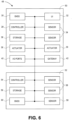
- FIG. 6 Another exemplary electronic system is illustrated in Fig. 6 .
- the system 48 illustrated in Fig. 6 is similar to the system 26 illustrated in Fig. 5A except that the system 48 includes a first portion 50 comprising components housed on the tractor 18 and a second portion 52 comprising components housed on the baler 20.
- the first portion 50 includes the same components as the system 26, described above.
- the second portion 52 includes a controller 54, a data storage component 56, one or more sensors 58 and a position determining component 60.
- the components 54, 56, 58, 60 of the second portion 52 function in a similar way to the components of the system 26 with the same name.
- the two portions 50, 52 may be in communication via wired or wireless communications.
- one or more of the sensors 58 may include a compass, inclinometer, and/or a position determining device housed on the baler 20 and used to determine the location, orientation or both of bales formed by the baler 20 and left on the ground surface.
- One of the sensors 58 may detect the weight of a formed bale in the baler.
- the communications and control system determines a location and an orientation of the bale on the ground surface.
- the location of the bale may correspond to a geographic location indicated by, for example, longitude and latitude coordinates.
- the orientation of the bale may include the position of a horizontal axis of the bale about a vertical axis of the bale, a pitch of the bale and/or a roll of the bale.
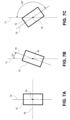
- FIG. 7A-C Various positions of a horizontal axis of a bale 62 about a vertical axis are illustrated in Figs. 7A-C .
- FIGs. 7A-7C is a top view of the bale 62 illustrating a longitudinal horizontal axis 64 and a lateral horizontal axis 66, wherein a vertical axis of the bale is normal to the plane of the drawing and is represented by the center point 68.
- the orientation of the bale 62 corresponds to the position of the longitudinal axis 64 relative to a north-south line 70 (or other cardinal direction).
- Fig. 7A-7C is a top view of the bale 62 illustrating a longitudinal horizontal axis 64 and a lateral horizontal axis 66, wherein a vertical axis of the bale is normal to the plane of the drawing and is represented by the center point 68.
- the orientation of the bale 62 corresponds to the position of the longitudinal axis 64 relative to a north
- the bale 62 is positioned such that the horizontal axis 64 is parallel with the north-south line 70, therefore the orientation of the bale is 0°.
- the bale 62 is positioned such that the horizontal axis 64 is rotated clockwise approximately 20° relative to the north-south line 70, therefore the orientation of the bale is 20°.
- the bale 62 is positioned such that the horizontal axis 64 is rotated clockwise approximately 145° relative to the north-south line 70, therefore the orientation of the bale is 145°.
- the orientation of the bale 62 is determined using an end of the bale that is on the east side of the north-south line 70 (that is, to the right of the north-south line 70 in the drawings). Thus, using this approach the orientation will always be between 0° and 180°.
- the longitudinal axis 64 of the bale 62 is used to determine the orientation of the bale, but it will be appreciated that the use of a different axis, such as the lateral axis 66, is within the ambit of the invention. It should also be noted that the pitch and roll of the bale 62 in this scenario are ignored.
- Figs. 8A-C Variations in the pitch of the bale 62 are illustrated in Figs. 8A-C , wherein the dashed line 72 represents level relative to gravity.
- the pitch of the bale 62 corresponds to the forward or backward tilt of the bale 62 or, in other words, the degree to which the longitudinal axis 64 of the bale 62 deviates from level.
- Fig. 8A the bale 62 is level and therefore has a pitch of 0°.
- Fig. 8B the bale 62 is 3° from level and therefore has a pitch of 3°.
- Fig. 8C the bale 62 is -4° from level and therefore has a pitch of -4°.
- Figs. 9A-C Variations in the roll of the bale 62 are illustrated in Figs. 9A-C , wherein the dashed line 76 represents level relative to gravity.
- the roll of the bale 62 corresponds to the lateral tilt of the bale 62 or, in other words, the degree to which the lateral axis 66 of the bale 62 deviates from level.
- Fig. 9A the bale 62 is level and therefore has a roll of 0°.
- Fig. 9B the bale 62 is 5° from level and therefore has a roll of 5°.
- Fig. 9C the bale 62 is -6° from level and therefore has a roll of -6°.
- a first method of determining the location and orientation of a bale involves using the location determining component 30, the compass 44 and the inclinometer 46 on the tractor 18 to determine a location and orientation of the tractor 18, and then using that information to determine the location and orientation of the bale on the ground surface.
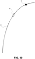
- the tractor 18 follows a path 80 during operation.
- the location determining component 30, the compass 44 and the inclinometer 46 continuously determine the location, the heading and the pitch and/or roll of the tractor 18, respectively.
- the system 26 associates a heading, pitch and roll of the tractor 18 with each new location generated by the location determining component 30.
- the path 80 comprises a series of locations of the tractor 18 as determined by the location determining component 30.
- the baler 20 trails the tractor 18 and, in most scenarios, follows the same path 80 as the tractor 18.
- the location of the tractor 18 at the time a bale is dropped will not correspond to the drop location of the bale because the baler 20 trails the tractor 18 and the bale is dropped from a rear portion of the baler 20, which may be several meters from the location of the tractor 18.
- the baler 20 follows the same path 80 as the tractor 18 therefore the location of the bale will correspond to a point on the travel path 80 of the tractor 18.
- the system 26 assigns to the bale a location corresponding to a location on the travel path 80 a predetermined distance behind the location of the tractor 18.
- the computing device also associates with the bale the orientation information associated with the location.
- the location determining component 30 records a location 82 of the tractor 18 at the time the bale is dropped. The system then determines the location of the bale as a predetermined distance along the path 80 behind the location 82 of the tractor at the time the bale was dropped.
- the predetermined distance may be provided by the manufacturer of the baling mechanism, or may be determined by the operator.
- the computing device stores in memory a list of locations and associated orientations corresponding to the path 80 followed by the tractor 18 and continuously revises the list to include the most recent travel path locations and associated orientations, and discards travel path information that is beyond a predetermined distance from the tractor 18.
- the system 26 automatically associates with the bale the travel path location 84 behind the tractor's location 82 and the orientation information associated with the location 84.
- the orientation information captured by the system 26 reflects the orientation of the ground surface corresponding to the location 84 because the tractor's orientation is determined by the ground surface.
- the orientation information associated with the location 84 also reflects the orientation of the bale, which rests upon the ground surface.
- the system 26 captures the location and orientation of the bale and stores it in memory, thereby collecting and storing the location and orientation information for a plurality of bales.
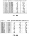
- Figures 11 through 13 depict the contents of computer-readable data tables stored in the memory and/or storage component containing location and orientation information for a plurality of bales.
- the data table illustrated in Fig. 11 includes a longitude value, a latitude value and one orientation value in each row of the table, each row corresponding to a unique bale.
- the orientation information in the table depicted in Fig. 11 includes only a position of the longitudinal horizontal axis 64 of the bale 62 about the vertical axis 68 of the bale 62.
- the data table illustrated in Fig. 12 is similar to the data table illustrated in Fig. 11 except that the table in Fig.
- the data table illustrated in Fig. 13 is also similar to the data table illustrated in Fig. 11 except that the table in Fig. 13 includes three pieces of orientation information-the position of the longitudinal horizontal axis of the bale about a vertical axis of the bale, the roll of the bale and the pitch of the bale.
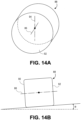
- a horizontal axis 86 of a round bale 88 corresponds to a line intersecting the center of each of two opposing planar faces 90, 92 of the bale 88.
- a first orientation of the round bale 88 may correspond to the position of the horizontal axis 86 about a vertical axis 94.
- a second orientation of the bale 88 may correspond to a tilt of the bale, or a deviation of the horizontal axis 86 from level represented by the angle ⁇ .
- a second method of determining the location and orientation of a bale is similar to the first method, described above, but does not involve the use of a compass to determine the heading of the tractor. Rather, the second method involves using two or more locations of the tractor 18, as determined by the location determining component 30, to determine the tractor's heading.
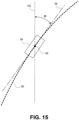
- Figure 15 illustrates in greater detail the travel path 80 and bale location 84 of Fig. 10 .
- a point 96 represents a center and vertical axis of the bale.
- the system 26 determines the location 84 of the bale and the position of the longitudinal horizontal axis 98 of the bale relative to a north-south line 100 as an angle ⁇ , as explained above.
- the longitudinal axis 98 of the bale is tangential with the travel path 80 at or near the center of the bale.
- the system 26 may use two points 102, 104 on the travel path near the center of the bale location 84 to define the longitudinal axis 98 of the bale.
- a third method of determining the location and orientation of a bale is similar to the first method described above, but involves using a location determining component 60, a compass and a tilt sensor on the baler 20 to determine a location and orientation of the baler 20, and then using that information to determine the location and orientation of the bale on the ground surface.
- This method may be implemented using the system 48 of Fig. 6 , and may involve detecting when a bale has dropped and associating a location with the dropped bale. If the location generated by the location determining component 60 does not correspond to the actual crop location of the bale, it may be necessary to apply an offset to the location generated by the location determining component to define the actual location of the bale in the field. This may be done in a manner similar to that described above, by defining a travel path of the baler 20 as a series of locations determined by a location-determining component and associating orientation information with each location.
Landscapes
- Engineering & Computer Science (AREA)
- Life Sciences & Earth Sciences (AREA)
- Environmental Sciences (AREA)
- Radar, Positioning & Navigation (AREA)
- Remote Sensing (AREA)
- Computer Networks & Wireless Communication (AREA)
- Physics & Mathematics (AREA)
- General Physics & Mathematics (AREA)
- Management, Administration, Business Operations System, And Electronic Commerce (AREA)
- Agricultural Machines (AREA)
Description
- The present invention relates to systems and methods for determining the orientation of a bale of agricultural product formed by a mobile baling mechanism and deposited on a ground surface.
- Hay and forage crops may be harvested by cutting the crops, allowing the crops to lie on the ground to dry, and then baling the dried crop. Baling the dried crop involves the use of balers that collect the crop from the ground as the baler travels along the ground, form the crop into a bale, tie or wrap the bale to preserve the bale's shape and/or protect it from the elements, and then place the bale onto the ground. Typically the bales are placed on the ground as they are formed by the baler such that a plurality of bales are placed randomly across a field. The bales are typically removed from the field shortly after baling and may be stacked in a convenient location in the field or in the same region, or may be transported to a distant location.
- United States patent application
US 2014/278083 describes a system comprising a mobile baling mechanism for creating a bale of agricultural product and placing the bale on a ground surface, and one or more computing devices for automatically determining a location and an orientation of the bale on the ground surface. - A further example is described in United States patent application
US 2006/086263 .EP 3 254 554 - A system in accordance with a first embodiment of the invention is recited in
claim 1 of the claims attached hereto. - A method in accordance with a second embodiment of the invention is recited in claim 9 of the claims attached hereto.
- These and other important aspects of the present invention are described more fully in the detailed description below. The invention is not limited to the particular methods and systems described herein. Other embodiments may be used and/or changes to the described embodiments may be made without departing from the scope of the claims that follow the detailed description.
- Embodiments of the present invention are described in detail below with reference to the attached drawing figures, wherein:
-
Fig. 1 is a perspective view of a plurality of round bales of agricultural product placed on the ground surface of a field. -
Fig. 2 is a perspective view of a plurality of rectangular bales of agricultural product placed on the ground surface of a field. -
Fig. 3 is a plan view of a plurality of rectangular bales of agricultural product placed on the ground surface of a field. -
Fig. 4 is a perspective view of a tractor and rectangular baler used to form rectangular bales of agricultural product. -
Figs. 5A-C are block diagrams of exemplary communications and control systems used in the tractor and/or baler ofFig. 4 . -
Fig. 6 is a block diagram of an exemplary communications and control system used in the tractor and baler ofFig. 4 . -
Figs. 7A-C illustrate a first orientation of a rectangular bale. -
Figs. 8A-C illustrate a second orientation of a rectangular bale. -
Figs. 9A-C illustrate a second orientation of a rectangular bale. -
Fig. 10 illustrates a path followed by the tractor and baler ofFig. 4 and the location of the tractor and bale on the path. -
Figs. 11-13 illustrate exemplary location and orientation information that may be stored in a computer-usable data table. -
Figs. 14A-B is a diagram of a round bale of agricultural product illustrating various axes of the bale. -
Figs. 15-16 are plan views of a rectangular bale of agricultural product in a field, illustrating how an orientation of the bale may be determined. - The drawing figures do not limit the present invention to the specific embodiments disclosed and described herein. The drawings are not necessarily to scale, emphasis instead being placed upon clearly illustrating the principles of the invention.
- The following detailed description of embodiments of the invention references the accompanying drawings. The embodiments are intended to describe aspects of the invention in sufficient detail to enable those skilled in the art to practice the invention. Other embodiments can be utilized and changes can be made without departing from the scope of the claims. The following description is, therefore, not to be taken in a limiting sense.
- In this description, references to "one embodiment", "an embodiment", or "embodiments" mean that the feature or features being referred to are included in at least one embodiment of the technology. Separate references to "one embodiment", "an embodiment", or "embodiments" in this description do not necessarily refer to the same embodiment and are also not mutually exclusive unless so stated and/or except as will be readily apparent to those skilled in the art from the description. For example, a feature, structure, act, etc. described in one embodiment may also be included in other embodiments, but is not necessarily included. Thus, the present technology can include a variety of combinations and/or integrations of the embodiments described herein.
- Embodiments of the invention involve a mobile baling mechanism for creating a bale of agricultural product and placing the bale on a ground surface, and a system for automatically determining a location and an orientation of the bale on the ground surface. The location of the bale may be defined by longitude and latitude coordinates of the bale. The orientation of the bale is the position of a horizontal axis of the bale about a vertical axis of the bale, such as the position of a horizontal axis of the bale relative to a cardinal direction. The invention may be used to collect and store location and orientation information for a plurality of bales in a field, and the information may be used to optimize collection of the plurality of bales.
- Exemplary bales of agricultural product are illustrated in
Figures 1 through 3 . Such bales may include a hay or forage crop for feeding livestock or may include straw or other biomass used for purposes other than feeding livestock.Round bales 10 are illustrated inFig. 1 andrectangular bales 12 are illustrated inFigs. 2 and3 . Theround bales 10 are generally cylindrical in shape with opposing flat end faces 14 defining a height of the bale and a cylindricalouter surface 16 defining a width of the bale between theend faces 14. Round bales typically range in size from one meter in height and one meter in width to two meters in height and two meters in width. The weight of such bales typically falls within the range of 180 kilograms to 780 kilograms depending on the size and density of the bale. Some common bale sizes include 1.3 meters wide by 1.5 meters high, 1.5 meters wide by 1.5 meters high, and 1.5 meters wide by 1.8 meters high. Some common bale weights include 270 kilograms, 360 kilograms, 450 kilograms and 550 kilograms. - There are two general sizes of rectangular bales-small and large. Generally, small rectangular bales may be moved by hand while large rectangular bales are too large to be moved by hand and require the use of machines. The
bales 12 illustrated inFigs. 2 and3 are large rectangular bales. Common sizes of large rectangular bales include 0.9 meters wide by 0.9 meters tall, 0.9 meters wide by 1.2 meters tall, and 1.2 meters wide by 1.2 meters tall. The length of large rectangular bales varies but is typically within the range of about 1.5 meters to about 2.5 meters, 1.8 meters is a common length. The weight of large rectangular bales typically falls within the range of 200 kilograms to 900 kilograms depending on the size and density of the bale. Some common bale weights include 360 kilograms, 450 kilograms, 550 kilograms and 640 kilograms. - A field may include a large number of bales, as illustrated in
Fig. 3 . Each of the bales is placed on the ground by a mobile baling mechanism as the bale is formed such that the location and orientation of each bale is random. The field ofFig. 3 is depicted in plan view such that changes in elevation across the field are not discernable, but areas of ground surface that are not level would cause the bales to be tilted along a longitudinal axis (pitch), along a lateral axis (roll), or both. - A mobile baling mechanism according to an embodiment of the invention includes a
tractor 18 coupled with a largesquare baler 20 as illustrated inFig. 4 . Thetractor 18 pulls thebaler 20 through a field and drives operation of thebaler 20 via a power takeoff of thetractor 18. A bale feeding system of the baler includes apickup 22 for collecting hay or other agricultural product from a ground surface and feeding the agricultural product into an internal bale forming system of the baler. The baler forms the hay into a bale, ties the bale, and discharges the formed bale onto the ground via achute 24 for conveying the bale to the ground surface. Thebaler 20 may include a weighing mechanism for determining a weight of the bale, and may include a sensor for determining when a bale has been deposited on the ground surface, as explained in greater detail below. - The
tractor 18, thebaler 20, or both may include a control and communications system. Various components of an exemplary control andcommunications system 26 are illustrated inFigs. 5A-C . Thesystem 26 broadly includes acontroller 28, aposition determining device 30, auser interface 32, one ormore sensors 34, one ormore actuators 36, one or moredata storage components 38, one or more input/output ports 40 and acommunications gateway 42. - The
position determining device 30 may include a global navigation satellite system (GNSS) receiver, such as a device configured to receive signals from one or more positioning systems such as the United States' global positioning system (GPS), the European GALILEO system and/or the Russian GLONASS system, and to determine a location of the machine using the received signals. Theuser interface 32 includes components for receiving instructions or other input from a user and may include buttons, switches, dials, and microphones, as well as components for presenting information or data to users, such as displays, light-emitting diodes, audio speakers and so forth. Theuser interface 32 may include a touchscreen display capable of presenting visual representations of information or data and receiving instructions or input from the user via a single display surface. - The
sensors 34 may be associated with any of various components or functions of the host machine including, for example, various elements of the engine, transmission(s), and hydraulic and electrical systems. One or more of thesensors 34 may be configured and placed to detect environmental or ambient conditions in, around or near the host machine. One of the sensors may be acompass 44, as illustrated inFig. 5B , used to detect a heading of the machine. Another of the sensors may be aninclinometer 46 for detecting pitch and roll of the machine. The system illustrated inFig. 5C includes both acompass 44 and aninclinometer 46. - The
actuators 36 are configured and placed to drive certain functions of the machine including, for example, steering when an automated guidance function is engaged. Theactuators 36 may take virtually any form but are generally configured to receive control signals or instructions from the controller 28 (or other component of the system 26) and to generate a mechanical movement or action in response to the control signals or instructions. By way of example, thesensors 34 andactuators 36 may be used in automated steering of a machine wherein thesensors 34 detect a current position or state of steered wheels or tracks and theactuators 36 drive steering action or operation of the wheels or tracks. - The
controller 28 includes one or more integrated circuits programmed or configured to implement the functions described herein. By way of example thecontroller 28 may be a digital controller and may include one or more general purpose microprocessors or microcontrollers, programmable logic devices, or application specific integrated circuits. Thecontroller 28 may include multiple computing components placed in various different locations on the machine. Thecontroller 28 may also include one or more discrete and/or analog circuit components operating in conjunction with the one or more integrated circuits or computing components. Furthermore, thecontroller 28 may include or have access to one or more memory elements operable to store executable instructions, data, or both. Thestorage device 38 stores data and preferably includes a non-volatile storage medium such as optic, magnetic or solid state technology. - In some embodiments, all of the components of the
system 26 are contained on or in a host machine, such as thetractor 18 or thebaler 20. The present invention is not so limited, however, and in other embodiments one or more of the components of thesystem 28 may be external to the machine. In another embodiment, for example, some of the components of thesystem 28 are contained on or in thetractor 10 while other components of thesystem 28 are contained on or in thebaler 20. In that embodiment, the components associated with thetractor 18 and the components associated with thebaler 20 may communicate via wired or wireless communications according to a local area network such as, for example, a controller area network. Thesystem 28 may be part of a communications and control system conforming to the ISO 11783 (also referred to as "ISOBUS") standard. In yet another exemplary embodiment, one or more components of thesystem 28 may be located remotely from the machine and any implements associated with the machine. In that embodiment, thesystem 28 may use wireless communications components (e.g., the gateway 42) to communicate with a remote computer, computer network or system. - Another exemplary electronic system is illustrated in
Fig. 6 . Thesystem 48 illustrated inFig. 6 is similar to thesystem 26 illustrated inFig. 5A except that thesystem 48 includes afirst portion 50 comprising components housed on thetractor 18 and asecond portion 52 comprising components housed on thebaler 20. Thefirst portion 50 includes the same components as thesystem 26, described above. Thesecond portion 52 includes acontroller 54, adata storage component 56, one ormore sensors 58 and aposition determining component 60. Thecomponents second portion 52 function in a similar way to the components of thesystem 26 with the same name. The twoportions sensors 58 may include a compass, inclinometer, and/or a position determining device housed on thebaler 20 and used to determine the location, orientation or both of bales formed by thebaler 20 and left on the ground surface. One of thesensors 58 may detect the weight of a formed bale in the baler. - It will be appreciated that, for simplicity, certain elements and components of the
systems Figs. 5 and6 . A power source or power connector is also associated with thesystems - In operation, as the
baler 20 forms a bale of agricultural product and places the bale on the ground the communications and control system determines a location and an orientation of the bale on the ground surface. The location of the bale may correspond to a geographic location indicated by, for example, longitude and latitude coordinates. The orientation of the bale may include the position of a horizontal axis of the bale about a vertical axis of the bale, a pitch of the bale and/or a roll of the bale. - Various positions of a horizontal axis of a
bale 62 about a vertical axis are illustrated inFigs. 7A-C . Each ofFigs. 7A-7C is a top view of thebale 62 illustrating a longitudinalhorizontal axis 64 and a lateralhorizontal axis 66, wherein a vertical axis of the bale is normal to the plane of the drawing and is represented by thecenter point 68. The orientation of thebale 62 corresponds to the position of thelongitudinal axis 64 relative to a north-south line 70 (or other cardinal direction). InFig. 7A , thebale 62 is positioned such that thehorizontal axis 64 is parallel with the north-south line 70, therefore the orientation of the bale is 0°. InFig. 7B thebale 62 is positioned such that thehorizontal axis 64 is rotated clockwise approximately 20° relative to the north-south line 70, therefore the orientation of the bale is 20°. InFig. 7C thebale 62 is positioned such that thehorizontal axis 64 is rotated clockwise approximately 145° relative to the north-south line 70, therefore the orientation of the bale is 145°. The orientation of thebale 62 is determined using an end of the bale that is on the east side of the north-south line 70 (that is, to the right of the north-south line 70 in the drawings). Thus, using this approach the orientation will always be between 0° and 180°. - In the example illustrated in
Fig. 7 thelongitudinal axis 64 of thebale 62 is used to determine the orientation of the bale, but it will be appreciated that the use of a different axis, such as thelateral axis 66, is within the ambit of the invention. It should also be noted that the pitch and roll of thebale 62 in this scenario are ignored. - Variations in the pitch of the
bale 62 are illustrated inFigs. 8A-C , wherein the dashedline 72 represents level relative to gravity. The pitch of thebale 62 corresponds to the forward or backward tilt of thebale 62 or, in other words, the degree to which thelongitudinal axis 64 of thebale 62 deviates from level. InFig. 8A thebale 62 is level and therefore has a pitch of 0°. InFig. 8B thebale 62 is 3° from level and therefore has a pitch of 3°. InFig. 8C thebale 62 is -4° from level and therefore has a pitch of -4°. To distinguish between positive and negative pitch, if the end of thebale 62 east of the north-south line 70 (to the right of the north-south line 70 inFig. 7A ) is lowest the pitch is positive and if the end of thebale 62 east of the north-south line 70 is highest the pitch is negative. Thus, inFigs. 8B and 8C theend 74 of thebale 62 is to the east of the north-south line 70. - Variations in the roll of the
bale 62 are illustrated inFigs. 9A-C , wherein the dashedline 76 represents level relative to gravity. The roll of thebale 62 corresponds to the lateral tilt of thebale 62 or, in other words, the degree to which thelateral axis 66 of thebale 62 deviates from level. InFig. 9A thebale 62 is level and therefore has a roll of 0°. InFig. 9B thebale 62 is 5° from level and therefore has a roll of 5°. InFig. 9C thebale 62 is -6° from level and therefore has a roll of -6°. To distinguish between positive and negative roll, if the side of thebale 62 east of the north-south line 70 (to the right of the north-south line 70 inFig. 7A ) is highest the roll is positive and if the side of thebale 62 west of the north-south line 70 is lowest the roll is negative. Thus, inFigs. 9B and 9C the side 78 of thebale 62 is to the east of the north-south line 70. - A first method of determining the location and orientation of a bale involves using the
location determining component 30, thecompass 44 and theinclinometer 46 on thetractor 18 to determine a location and orientation of thetractor 18, and then using that information to determine the location and orientation of the bale on the ground surface. As illustrated inFig. 10 thetractor 18 follows apath 80 during operation. As thetractor 18 moves along thepath 80, thelocation determining component 30, thecompass 44 and theinclinometer 46 continuously determine the location, the heading and the pitch and/or roll of thetractor 18, respectively. Thesystem 26 associates a heading, pitch and roll of thetractor 18 with each new location generated by thelocation determining component 30. Thepath 80 comprises a series of locations of thetractor 18 as determined by thelocation determining component 30. Thebaler 20 trails thetractor 18 and, in most scenarios, follows thesame path 80 as thetractor 18. - The location of the
tractor 18 at the time a bale is dropped, as determined by thelocation determining component 30, will not correspond to the drop location of the bale because thebaler 20 trails thetractor 18 and the bale is dropped from a rear portion of thebaler 20, which may be several meters from the location of thetractor 18. However, thebaler 20 follows thesame path 80 as thetractor 18 therefore the location of the bale will correspond to a point on thetravel path 80 of thetractor 18. Thus, to resolve the discrepancy between the location of thetractor 18 and the location of the bale at the time the bale is dropped, thesystem 26 assigns to the bale a location corresponding to a location on the travel path 80 a predetermined distance behind the location of thetractor 18. The computing device also associates with the bale the orientation information associated with the location. - As illustrated in
Figure 10 , thelocation determining component 30 records alocation 82 of thetractor 18 at the time the bale is dropped. The system then determines the location of the bale as a predetermined distance along thepath 80 behind thelocation 82 of the tractor at the time the bale was dropped. The predetermined distance may be provided by the manufacturer of the baling mechanism, or may be determined by the operator. - The computing device stores in memory a list of locations and associated orientations corresponding to the
path 80 followed by thetractor 18 and continuously revises the list to include the most recent travel path locations and associated orientations, and discards travel path information that is beyond a predetermined distance from thetractor 18. When a bale drop is sensed thesystem 26 automatically associates with the bale thetravel path location 84 behind the tractor'slocation 82 and the orientation information associated with thelocation 84. - The orientation information captured by the
system 26 reflects the orientation of the ground surface corresponding to thelocation 84 because the tractor's orientation is determined by the ground surface. Thus, the orientation information associated with thelocation 84 also reflects the orientation of the bale, which rests upon the ground surface. Each time a bale is dropped thesystem 26 captures the location and orientation of the bale and stores it in memory, thereby collecting and storing the location and orientation information for a plurality of bales. -
Figures 11 through 13 depict the contents of computer-readable data tables stored in the memory and/or storage component containing location and orientation information for a plurality of bales. The data table illustrated inFig. 11 includes a longitude value, a latitude value and one orientation value in each row of the table, each row corresponding to a unique bale. The orientation information in the table depicted inFig. 11 includes only a position of the longitudinalhorizontal axis 64 of thebale 62 about thevertical axis 68 of thebale 62. The data table illustrated inFig. 12 is similar to the data table illustrated inFig. 11 except that the table inFig. 12 includes two pieces of orientation information-the position of the longitudinal horizontal axis of the bale about a vertical axis of the bale and the roll of the bale. The data table illustrated inFig. 13 is also similar to the data table illustrated inFig. 11 except that the table inFig. 13 includes three pieces of orientation information-the position of the longitudinal horizontal axis of the bale about a vertical axis of the bale, the roll of the bale and the pitch of the bale. - This method may be used with a system that includes machines other than a tractor and a rectangular baler, it will be appreciated that the invention is not so limited and that other types of baling mechanisms may be used as well. The system may be used with a round baler, for example, in a manner very similar to that described above. As illustrated in
Fig. 14A , ahorizontal axis 86 of around bale 88 corresponds to a line intersecting the center of each of two opposing planar faces 90, 92 of thebale 88. A first orientation of theround bale 88 may correspond to the position of thehorizontal axis 86 about avertical axis 94. With reference toFig. 14B , a second orientation of thebale 88 may correspond to a tilt of the bale, or a deviation of thehorizontal axis 86 from level represented by the angle Θ. - A second method of determining the location and orientation of a bale is similar to the first method, described above, but does not involve the use of a compass to determine the heading of the tractor. Rather, the second method involves using two or more locations of the
tractor 18, as determined by thelocation determining component 30, to determine the tractor's heading.Figure 15 illustrates in greater detail thetravel path 80 andbale location 84 ofFig. 10 . Apoint 96 represents a center and vertical axis of the bale. Thesystem 26 determines thelocation 84 of the bale and the position of the longitudinalhorizontal axis 98 of the bale relative to a north-south line 100 as an angle Φ, as explained above. As illustrated inFig. 15 , thelongitudinal axis 98 of the bale is tangential with thetravel path 80 at or near the center of the bale. - Given that the
longitudinal axis 98 of the bale is tangential with thetravel path 80 at or near the center of the bale, thesystem 26 may use twopoints bale location 84 to define thelongitudinal axis 98 of the bale. - A third method of determining the location and orientation of a bale is similar to the first method described above, but involves using a
location determining component 60, a compass and a tilt sensor on thebaler 20 to determine a location and orientation of thebaler 20, and then using that information to determine the location and orientation of the bale on the ground surface. This method may be implemented using thesystem 48 ofFig. 6 , and may involve detecting when a bale has dropped and associating a location with the dropped bale. If the location generated by thelocation determining component 60 does not correspond to the actual crop location of the bale, it may be necessary to apply an offset to the location generated by the location determining component to define the actual location of the bale in the field. This may be done in a manner similar to that described above, by defining a travel path of thebaler 20 as a series of locations determined by a location-determining component and associating orientation information with each location. - Although the invention has been described with reference to the preferred embodiment illustrated in the attached drawing figures, it is noted that equivalents may be employed and substitutions made herein without departing from the scope of the invention as recited in the claims. For example, while various methods of determining the orientation of a bale have been described above, it will be appreciated that these methods are exemplary in nature and that other methods may be used without departing from the scope of the invention as recited in the claims.
Claims (11)
- A system for determining bale location and orientation comprising:a mobile baling mechanism (18, 20) operable to create a bale (10, 12, 62) of agricultural product and place the bale on a ground surface; andone or more computing devices (28, 54) configured to automatically determine a location and an orientation of the bale (10, 12, 62) on the ground surface;characterized in that the one or more computing devices (28, 54) are configured to determine the orientation of the bale (10, 12, 62) as a position of a horizontal axis (64) of the bale (10, 12, 62) about a vertical axis (68) of the bale, as a pitch and a roll of the bale.
- The system as set forth in claim 1, further comprising a compass (44) for determining an orientation of the baling mechanism (18, 20), the one or more computing devices (28, 54) configured to automatically determine the orientation of the bale (10, 12, 62) using information from the compass (44).
- The system as set forth in claim 1, further comprising a location determining component (30) for determining a location of the baling mechanism (18, 20), the one or more computing devices (28, 54) configured to -determine the location of the bale (10, 12, 62) using the location determined by the location determining component (30),determine a heading of the baling mechanism (18, 20) using two or more locations as determined by the location determining component (30), anddetermine the orientation of the bale (10, 12, 62) using the heading.
- The system as set forth in claim 1, the one or more computing devices (28, 54) configured to determine at least one axis of the orientation of the bale (10, 12, 62) relative to a cardinal direction (70).
- The system as set forth in claim 1, the one or more computing devices (28, 54) configured to determine at least one axis of the orientation of the bale (10, 12, 62) relative to an environmental landmark.
- The system as set forth in claim 1, the one or more computing devices (28, 54) configured to determine at least one axis of the orientation of the bale (10, 12, 62) relative to an orientation of another bale (10, 12, 62).
- The system as set forth in claim 1, the one or more computing devices (28, 54) configured to assign position and orientation information to a plurality of bales (10, 12, 62) created by the baling mechanism (18, 20) and placed on the ground surface, and to store the position and orientation information for all of the plurality of bales (10, 12, 62) as digital data in a data storage device (38, 56).
- The system as set forth in claim 7, the one or more computing devices (28, 54) configured to generate a map illustrating the location and orientation of each of the bales (10, 12, 62).
- A method for determining bale location and orientation comprising:creating a bale (10, 12, 62) of agricultural product using a mobile baling mechanism (18, 20) and placing the bale on a ground surface; andusing one or more computing devices (28, 54) to automatically determine an orientation of the bale (10, 12, 62) on the ground surface;characterized in that the step of automatically determining an orientation of the bale (10, 12, 62) on the ground surface includes automatically determining a position of a horizontal axis (64) of the bale (10, 12, 62) about a vertical axis (68) of the bale as a pitch and a roll of the bale.
- The method as set forth in claim 9, further comprising using information from a compass (44) to automatically determine an orientation of the baling mechanism (18, 20).
- The method as set forth in claim 9, further comprising -using information from a location determining component (30) to automatically determine a location of the baling mechanism (18, 20),using the one or more computing devices (28, 54) to automatically determine a heading of the baling mechanism (18, 20) using two or more locations as determined by the location determining component (30), andusing the one or more computing devices (28, 54) to automatically determine the orientation of the bale (10, 12, 62) using the heading.
Applications Claiming Priority (2)
| Application Number | Priority Date | Filing Date | Title |
|---|---|---|---|
| US201762466047P | 2017-03-02 | 2017-03-02 | |
| PCT/IB2018/000028 WO2018158630A1 (en) | 2017-03-02 | 2018-01-19 | System and method for determining bale location and orientation |
Publications (2)
| Publication Number | Publication Date |
|---|---|
| EP3589112A1 EP3589112A1 (en) | 2020-01-08 |
| EP3589112B1 true EP3589112B1 (en) | 2023-08-09 |
Family
ID=61599524
Family Applications (1)
| Application Number | Title | Priority Date | Filing Date |
|---|---|---|---|
| EP18709764.7A Active EP3589112B1 (en) | 2017-03-02 | 2018-01-19 | System and method for determining bale location and orientation |
Country Status (3)
| Country | Link |
|---|---|
| US (1) | US20210105948A1 (en) |
| EP (1) | EP3589112B1 (en) |
| WO (1) | WO2018158630A1 (en) |
Families Citing this family (3)
| Publication number | Priority date | Publication date | Assignee | Title |
|---|---|---|---|---|
| US11140827B2 (en) | 2020-01-17 | 2021-10-12 | Cnh Industrial Canada, Ltd. | Round bale aligner and accumulator |
| US20220225571A1 (en) * | 2021-01-18 | 2022-07-21 | Cnh Industrial America Llc | Autonomous bale retrieval system |
| JP2025025424A (en) * | 2023-08-09 | 2025-02-21 | 井関農機株式会社 | Work vehicles |
Citations (1)
| Publication number | Priority date | Publication date | Assignee | Title |
|---|---|---|---|---|
| EP3254554A1 (en) * | 2016-06-09 | 2017-12-13 | Deere & Company | Baler information system and method |
Family Cites Families (4)
| Publication number | Priority date | Publication date | Assignee | Title |
|---|---|---|---|---|
| DE102004027895A1 (en) * | 2004-06-09 | 2006-01-05 | Claas Selbstfahrende Erntemaschinen Gmbh | Ball filing system |
| ATE514330T1 (en) * | 2008-07-31 | 2011-07-15 | Deere & Co | BALER AND WRAPPER COMBINATION |
| US10292336B2 (en) * | 2012-08-22 | 2019-05-21 | Agco Corporation | System for optimizing bale drop locations within a field |
| US8942897B2 (en) * | 2013-03-18 | 2015-01-27 | Cnh Industrial America Llc | System and method for determining a location of an unloaded unit of agricultural product and locating a desired unit of agricultural product |
-
2018
- 2018-01-19 EP EP18709764.7A patent/EP3589112B1/en active Active
- 2018-01-19 US US16/488,855 patent/US20210105948A1/en not_active Abandoned
- 2018-01-19 WO PCT/IB2018/000028 patent/WO2018158630A1/en not_active Ceased
Patent Citations (1)
| Publication number | Priority date | Publication date | Assignee | Title |
|---|---|---|---|---|
| EP3254554A1 (en) * | 2016-06-09 | 2017-12-13 | Deere & Company | Baler information system and method |
Also Published As
| Publication number | Publication date |
|---|---|
| EP3589112A1 (en) | 2020-01-08 |
| US20210105948A1 (en) | 2021-04-15 |
| WO2018158630A1 (en) | 2018-09-07 |
Similar Documents
| Publication | Publication Date | Title |
|---|---|---|
| ES2762607T3 (en) | Method and arrangement to monitor the collection of plant material | |
| EP3939406A1 (en) | System and method of assisted or automated grain unload synchronization | |
| EP3841868B1 (en) | System and method for windrow path planning | |
| CN104936430B (en) | Agricultural machine, agricultural work management method | |
| US12433182B2 (en) | Farming support system, position information generation method, computer program, and processing device | |
| BR102016025339A2 (en) | agricultural equipment baler and agricultural equipment brushcutter | |
| US20080030320A1 (en) | Agricultural lift with data gathering capability | |
| US20210105948A1 (en) | System and method for determining bale location and orientation | |
| BR102022004881A2 (en) | AGRICULTURAL SYSTEM AND METHOD FOR CONTROLLING AN END SPLITTER IN AN AGRICULTURAL HARVEST HEAD | |
| KR102331105B1 (en) | Quantity information display system | |
| JP5806997B2 (en) | Farm work information management apparatus and farm work information management system | |
| EP3939410A1 (en) | System and method of assisted or automated grain unload synchronization | |
| US20210195825A1 (en) | System and method for windrow path planning | |
| US11268815B2 (en) | System and method of bale collection | |
| EP3534321A1 (en) | Agricultural crop package retrieval and tracking system and method | |
| US20180252531A1 (en) | System and method of bale collection | |
| US11280614B2 (en) | System and method of bale collection | |
| ES3032405T3 (en) | Method for controlling the environment of an autonomous agricultural feeding machine and system for controlling the environment of such a machine | |
| JP2020162490A (en) | Spraying support device and spraying support system | |
| JP5881573B2 (en) | Farm work information management apparatus and farm work information management system | |
| US20030226340A1 (en) | A device for crop processing | |
| JP2021048799A (en) | Spray supporting system | |
| EP4191197A1 (en) | High vantage point bale locator | |
| US20180252530A1 (en) | System and method of bale collection | |
| Khosro-Anjom et al. | A low-cost, efficient strawberry yield monitoring system |
Legal Events
| Date | Code | Title | Description |
|---|---|---|---|
| STAA | Information on the status of an ep patent application or granted ep patent |
Free format text: STATUS: UNKNOWN |
|
| STAA | Information on the status of an ep patent application or granted ep patent |
Free format text: STATUS: THE INTERNATIONAL PUBLICATION HAS BEEN MADE |
|
| PUAI | Public reference made under article 153(3) epc to a published international application that has entered the european phase |
Free format text: ORIGINAL CODE: 0009012 |
|
| STAA | Information on the status of an ep patent application or granted ep patent |
Free format text: STATUS: REQUEST FOR EXAMINATION WAS MADE |
|
| 17P | Request for examination filed |
Effective date: 20191002 |
|
| AK | Designated contracting states |
Kind code of ref document: A1 Designated state(s): AL AT BE BG CH CY CZ DE DK EE ES FI FR GB GR HR HU IE IS IT LI LT LU LV MC MK MT NL NO PL PT RO RS SE SI SK SM TR |
|
| AX | Request for extension of the european patent |
Extension state: BA ME |
|
| DAV | Request for validation of the european patent (deleted) | ||
| DAX | Request for extension of the european patent (deleted) | ||
| STAA | Information on the status of an ep patent application or granted ep patent |
Free format text: STATUS: EXAMINATION IS IN PROGRESS |
|
| 17Q | First examination report despatched |
Effective date: 20210408 |
|
| GRAP | Despatch of communication of intention to grant a patent |
Free format text: ORIGINAL CODE: EPIDOSNIGR1 |
|
| STAA | Information on the status of an ep patent application or granted ep patent |
Free format text: STATUS: GRANT OF PATENT IS INTENDED |
|
| INTG | Intention to grant announced |
Effective date: 20230303 |
|
| P01 | Opt-out of the competence of the unified patent court (upc) registered |
Effective date: 20230518 |
|
| GRAS | Grant fee paid |
Free format text: ORIGINAL CODE: EPIDOSNIGR3 |
|
| GRAA | (expected) grant |
Free format text: ORIGINAL CODE: 0009210 |
|
| STAA | Information on the status of an ep patent application or granted ep patent |
Free format text: STATUS: THE PATENT HAS BEEN GRANTED |
|
| AK | Designated contracting states |
Kind code of ref document: B1 Designated state(s): AL AT BE BG CH CY CZ DE DK EE ES FI FR GB GR HR HU IE IS IT LI LT LU LV MC MK MT NL NO PL PT RO RS SE SI SK SM TR |
|
| REG | Reference to a national code |
Ref country code: GB Ref legal event code: FG4D |
|
| REG | Reference to a national code |
Ref country code: CH Ref legal event code: EP |
|
| REG | Reference to a national code |
Ref country code: DE Ref legal event code: R096 Ref document number: 602018054944 Country of ref document: DE |
|
| REG | Reference to a national code |
Ref country code: IE Ref legal event code: FG4D |
|
| REG | Reference to a national code |
Ref country code: LT Ref legal event code: MG9D |
|
| REG | Reference to a national code |
Ref country code: NL Ref legal event code: MP Effective date: 20230809 |
|
| REG | Reference to a national code |
Ref country code: AT Ref legal event code: MK05 Ref document number: 1596377 Country of ref document: AT Kind code of ref document: T Effective date: 20230809 |
|
| PG25 | Lapsed in a contracting state [announced via postgrant information from national office to epo] |
Ref country code: GR Free format text: LAPSE BECAUSE OF FAILURE TO SUBMIT A TRANSLATION OF THE DESCRIPTION OR TO PAY THE FEE WITHIN THE PRESCRIBED TIME-LIMIT Effective date: 20231110 |
|
| PG25 | Lapsed in a contracting state [announced via postgrant information from national office to epo] |
Ref country code: IS Free format text: LAPSE BECAUSE OF FAILURE TO SUBMIT A TRANSLATION OF THE DESCRIPTION OR TO PAY THE FEE WITHIN THE PRESCRIBED TIME-LIMIT Effective date: 20231209 |
|
| PG25 | Lapsed in a contracting state [announced via postgrant information from national office to epo] |
Ref country code: SE Free format text: LAPSE BECAUSE OF FAILURE TO SUBMIT A TRANSLATION OF THE DESCRIPTION OR TO PAY THE FEE WITHIN THE PRESCRIBED TIME-LIMIT Effective date: 20230809 Ref country code: RS Free format text: LAPSE BECAUSE OF FAILURE TO SUBMIT A TRANSLATION OF THE DESCRIPTION OR TO PAY THE FEE WITHIN THE PRESCRIBED TIME-LIMIT Effective date: 20230809 Ref country code: PT Free format text: LAPSE BECAUSE OF FAILURE TO SUBMIT A TRANSLATION OF THE DESCRIPTION OR TO PAY THE FEE WITHIN THE PRESCRIBED TIME-LIMIT Effective date: 20231211 Ref country code: NO Free format text: LAPSE BECAUSE OF FAILURE TO SUBMIT A TRANSLATION OF THE DESCRIPTION OR TO PAY THE FEE WITHIN THE PRESCRIBED TIME-LIMIT Effective date: 20231109 Ref country code: NL Free format text: LAPSE BECAUSE OF FAILURE TO SUBMIT A TRANSLATION OF THE DESCRIPTION OR TO PAY THE FEE WITHIN THE PRESCRIBED TIME-LIMIT Effective date: 20230809 Ref country code: LV Free format text: LAPSE BECAUSE OF FAILURE TO SUBMIT A TRANSLATION OF THE DESCRIPTION OR TO PAY THE FEE WITHIN THE PRESCRIBED TIME-LIMIT Effective date: 20230809 Ref country code: LT Free format text: LAPSE BECAUSE OF FAILURE TO SUBMIT A TRANSLATION OF THE DESCRIPTION OR TO PAY THE FEE WITHIN THE PRESCRIBED TIME-LIMIT Effective date: 20230809 Ref country code: IS Free format text: LAPSE BECAUSE OF FAILURE TO SUBMIT A TRANSLATION OF THE DESCRIPTION OR TO PAY THE FEE WITHIN THE PRESCRIBED TIME-LIMIT Effective date: 20231209 Ref country code: HR Free format text: LAPSE BECAUSE OF FAILURE TO SUBMIT A TRANSLATION OF THE DESCRIPTION OR TO PAY THE FEE WITHIN THE PRESCRIBED TIME-LIMIT Effective date: 20230809 Ref country code: GR Free format text: LAPSE BECAUSE OF FAILURE TO SUBMIT A TRANSLATION OF THE DESCRIPTION OR TO PAY THE FEE WITHIN THE PRESCRIBED TIME-LIMIT Effective date: 20231110 Ref country code: FI Free format text: LAPSE BECAUSE OF FAILURE TO SUBMIT A TRANSLATION OF THE DESCRIPTION OR TO PAY THE FEE WITHIN THE PRESCRIBED TIME-LIMIT Effective date: 20230809 Ref country code: AT Free format text: LAPSE BECAUSE OF FAILURE TO SUBMIT A TRANSLATION OF THE DESCRIPTION OR TO PAY THE FEE WITHIN THE PRESCRIBED TIME-LIMIT Effective date: 20230809 |
|
| PG25 | Lapsed in a contracting state [announced via postgrant information from national office to epo] |
Ref country code: PL Free format text: LAPSE BECAUSE OF FAILURE TO SUBMIT A TRANSLATION OF THE DESCRIPTION OR TO PAY THE FEE WITHIN THE PRESCRIBED TIME-LIMIT Effective date: 20230809 |
|
| PG25 | Lapsed in a contracting state [announced via postgrant information from national office to epo] |
Ref country code: ES Free format text: LAPSE BECAUSE OF FAILURE TO SUBMIT A TRANSLATION OF THE DESCRIPTION OR TO PAY THE FEE WITHIN THE PRESCRIBED TIME-LIMIT Effective date: 20230809 |
|
| PG25 | Lapsed in a contracting state [announced via postgrant information from national office to epo] |
Ref country code: SM Free format text: LAPSE BECAUSE OF FAILURE TO SUBMIT A TRANSLATION OF THE DESCRIPTION OR TO PAY THE FEE WITHIN THE PRESCRIBED TIME-LIMIT Effective date: 20230809 Ref country code: RO Free format text: LAPSE BECAUSE OF FAILURE TO SUBMIT A TRANSLATION OF THE DESCRIPTION OR TO PAY THE FEE WITHIN THE PRESCRIBED TIME-LIMIT Effective date: 20230809 Ref country code: ES Free format text: LAPSE BECAUSE OF FAILURE TO SUBMIT A TRANSLATION OF THE DESCRIPTION OR TO PAY THE FEE WITHIN THE PRESCRIBED TIME-LIMIT Effective date: 20230809 Ref country code: EE Free format text: LAPSE BECAUSE OF FAILURE TO SUBMIT A TRANSLATION OF THE DESCRIPTION OR TO PAY THE FEE WITHIN THE PRESCRIBED TIME-LIMIT Effective date: 20230809 Ref country code: DK Free format text: LAPSE BECAUSE OF FAILURE TO SUBMIT A TRANSLATION OF THE DESCRIPTION OR TO PAY THE FEE WITHIN THE PRESCRIBED TIME-LIMIT Effective date: 20230809 Ref country code: CZ Free format text: LAPSE BECAUSE OF FAILURE TO SUBMIT A TRANSLATION OF THE DESCRIPTION OR TO PAY THE FEE WITHIN THE PRESCRIBED TIME-LIMIT Effective date: 20230809 Ref country code: SK Free format text: LAPSE BECAUSE OF FAILURE TO SUBMIT A TRANSLATION OF THE DESCRIPTION OR TO PAY THE FEE WITHIN THE PRESCRIBED TIME-LIMIT Effective date: 20230809 |
|
| REG | Reference to a national code |
Ref country code: DE Ref legal event code: R097 Ref document number: 602018054944 Country of ref document: DE |
|
| PG25 | Lapsed in a contracting state [announced via postgrant information from national office to epo] |
Ref country code: IT Free format text: LAPSE BECAUSE OF FAILURE TO SUBMIT A TRANSLATION OF THE DESCRIPTION OR TO PAY THE FEE WITHIN THE PRESCRIBED TIME-LIMIT Effective date: 20230809 |
|
| PLBE | No opposition filed within time limit |
Free format text: ORIGINAL CODE: 0009261 |
|
| STAA | Information on the status of an ep patent application or granted ep patent |
Free format text: STATUS: NO OPPOSITION FILED WITHIN TIME LIMIT |
|
| 26N | No opposition filed |
Effective date: 20240513 |
|
| PG25 | Lapsed in a contracting state [announced via postgrant information from national office to epo] |
Ref country code: SI Free format text: LAPSE BECAUSE OF FAILURE TO SUBMIT A TRANSLATION OF THE DESCRIPTION OR TO PAY THE FEE WITHIN THE PRESCRIBED TIME-LIMIT Effective date: 20230809 |
|
| PG25 | Lapsed in a contracting state [announced via postgrant information from national office to epo] |
Ref country code: MC Free format text: LAPSE BECAUSE OF FAILURE TO SUBMIT A TRANSLATION OF THE DESCRIPTION OR TO PAY THE FEE WITHIN THE PRESCRIBED TIME-LIMIT Effective date: 20230809 |
|
| PG25 | Lapsed in a contracting state [announced via postgrant information from national office to epo] |
Ref country code: MC Free format text: LAPSE BECAUSE OF FAILURE TO SUBMIT A TRANSLATION OF THE DESCRIPTION OR TO PAY THE FEE WITHIN THE PRESCRIBED TIME-LIMIT Effective date: 20230809 |
|
| REG | Reference to a national code |
Ref country code: CH Ref legal event code: PL |
|
| PG25 | Lapsed in a contracting state [announced via postgrant information from national office to epo] |
Ref country code: LU Free format text: LAPSE BECAUSE OF NON-PAYMENT OF DUE FEES Effective date: 20240119 |
|
| GBPC | Gb: european patent ceased through non-payment of renewal fee |
Effective date: 20240119 |
|
| PG25 | Lapsed in a contracting state [announced via postgrant information from national office to epo] |
Ref country code: LU Free format text: LAPSE BECAUSE OF NON-PAYMENT OF DUE FEES Effective date: 20240119 |
|
| PG25 | Lapsed in a contracting state [announced via postgrant information from national office to epo] |
Ref country code: GB Free format text: LAPSE BECAUSE OF NON-PAYMENT OF DUE FEES Effective date: 20240119 |
|
| PG25 | Lapsed in a contracting state [announced via postgrant information from national office to epo] |
Ref country code: BE Free format text: LAPSE BECAUSE OF NON-PAYMENT OF DUE FEES Effective date: 20240131 |
|
| PG25 | Lapsed in a contracting state [announced via postgrant information from national office to epo] |
Ref country code: CH Free format text: LAPSE BECAUSE OF NON-PAYMENT OF DUE FEES Effective date: 20240131 |
|
| PG25 | Lapsed in a contracting state [announced via postgrant information from national office to epo] |
Ref country code: GB Free format text: LAPSE BECAUSE OF NON-PAYMENT OF DUE FEES Effective date: 20240119 Ref country code: CH Free format text: LAPSE BECAUSE OF NON-PAYMENT OF DUE FEES Effective date: 20240131 Ref country code: BE Free format text: LAPSE BECAUSE OF NON-PAYMENT OF DUE FEES Effective date: 20240131 |
|
| REG | Reference to a national code |
Ref country code: BE Ref legal event code: MM Effective date: 20240131 |
|
| PG25 | Lapsed in a contracting state [announced via postgrant information from national office to epo] |
Ref country code: BG Free format text: LAPSE BECAUSE OF FAILURE TO SUBMIT A TRANSLATION OF THE DESCRIPTION OR TO PAY THE FEE WITHIN THE PRESCRIBED TIME-LIMIT Effective date: 20230809 |
|
| PG25 | Lapsed in a contracting state [announced via postgrant information from national office to epo] |
Ref country code: BG Free format text: LAPSE BECAUSE OF FAILURE TO SUBMIT A TRANSLATION OF THE DESCRIPTION OR TO PAY THE FEE WITHIN THE PRESCRIBED TIME-LIMIT Effective date: 20230809 |
|
| PG25 | Lapsed in a contracting state [announced via postgrant information from national office to epo] |
Ref country code: IE Free format text: LAPSE BECAUSE OF NON-PAYMENT OF DUE FEES Effective date: 20240119 |
|
| PG25 | Lapsed in a contracting state [announced via postgrant information from national office to epo] |
Ref country code: IE Free format text: LAPSE BECAUSE OF NON-PAYMENT OF DUE FEES Effective date: 20240119 |
|
| PG25 | Lapsed in a contracting state [announced via postgrant information from national office to epo] |
Ref country code: CY Free format text: LAPSE BECAUSE OF FAILURE TO SUBMIT A TRANSLATION OF THE DESCRIPTION OR TO PAY THE FEE WITHIN THE PRESCRIBED TIME-LIMIT; INVALID AB INITIO Effective date: 20180119 |
|
| PG25 | Lapsed in a contracting state [announced via postgrant information from national office to epo] |
Ref country code: HU Free format text: LAPSE BECAUSE OF FAILURE TO SUBMIT A TRANSLATION OF THE DESCRIPTION OR TO PAY THE FEE WITHIN THE PRESCRIBED TIME-LIMIT; INVALID AB INITIO Effective date: 20180119 |
|
| PG25 | Lapsed in a contracting state [announced via postgrant information from national office to epo] |
Ref country code: TR Free format text: LAPSE BECAUSE OF FAILURE TO SUBMIT A TRANSLATION OF THE DESCRIPTION OR TO PAY THE FEE WITHIN THE PRESCRIBED TIME-LIMIT Effective date: 20230809 |
|
| PGFP | Annual fee paid to national office [announced via postgrant information from national office to epo] |
Ref country code: DE Payment date: 20260121 Year of fee payment: 9 |
|
| PGFP | Annual fee paid to national office [announced via postgrant information from national office to epo] |
Ref country code: FR Payment date: 20260123 Year of fee payment: 9 |