EP3589453B1 - Outil d'accès de puits - Google Patents
Outil d'accès de puits Download PDFInfo
- Publication number
- EP3589453B1 EP3589453B1 EP18708409.0A EP18708409A EP3589453B1 EP 3589453 B1 EP3589453 B1 EP 3589453B1 EP 18708409 A EP18708409 A EP 18708409A EP 3589453 B1 EP3589453 B1 EP 3589453B1
- Authority
- EP
- European Patent Office
- Prior art keywords
- shaft
- tool
- head portion
- forwardly
- lateral access
- Prior art date
- Legal status (The legal status is an assumption and is not a legal conclusion. Google has not performed a legal analysis and makes no representation as to the accuracy of the status listed.)
- Active
Links
Images



Classifications
-
- B—PERFORMING OPERATIONS; TRANSPORTING
- B25—HAND TOOLS; PORTABLE POWER-DRIVEN TOOLS; MANIPULATORS
- B25B—TOOLS OR BENCH DEVICES NOT OTHERWISE PROVIDED FOR, FOR FASTENING, CONNECTING, DISENGAGING OR HOLDING
- B25B23/00—Details of, or accessories for, spanners, wrenches, screwdrivers
- B25B23/0007—Connections or joints between tool parts
- B25B23/0014—Screwdriver- or wrench-heads provided with cardan joints or the like
-
- B—PERFORMING OPERATIONS; TRANSPORTING
- B25—HAND TOOLS; PORTABLE POWER-DRIVEN TOOLS; MANIPULATORS
- B25B—TOOLS OR BENCH DEVICES NOT OTHERWISE PROVIDED FOR, FOR FASTENING, CONNECTING, DISENGAGING OR HOLDING
- B25B23/00—Details of, or accessories for, spanners, wrenches, screwdrivers
- B25B23/0007—Connections or joints between tool parts
- B25B23/0021—Prolongations interposed between handle and tool
-
- B—PERFORMING OPERATIONS; TRANSPORTING
- B25—HAND TOOLS; PORTABLE POWER-DRIVEN TOOLS; MANIPULATORS
- B25B—TOOLS OR BENCH DEVICES NOT OTHERWISE PROVIDED FOR, FOR FASTENING, CONNECTING, DISENGAGING OR HOLDING
- B25B23/00—Details of, or accessories for, spanners, wrenches, screwdrivers
- B25B23/14—Arrangement of torque limiters or torque indicators in wrenches or screwdrivers
-
- E—FIXED CONSTRUCTIONS
- E21—EARTH OR ROCK DRILLING; MINING
- E21B—EARTH OR ROCK DRILLING; OBTAINING OIL, GAS, WATER, SOLUBLE OR MELTABLE MATERIALS OR A SLURRY OF MINERALS FROM WELLS
- E21B17/00—Drilling rods or pipes; Flexible drill strings; Kellies; Drill collars; Sucker rods; Cables; Casings; Tubings
- E21B17/02—Couplings; joints
- E21B17/021—Devices for subsurface connecting or disconnecting by rotation
-
- E—FIXED CONSTRUCTIONS
- E21—EARTH OR ROCK DRILLING; MINING
- E21B—EARTH OR ROCK DRILLING; OBTAINING OIL, GAS, WATER, SOLUBLE OR MELTABLE MATERIALS OR A SLURRY OF MINERALS FROM WELLS
- E21B33/00—Sealing or packing boreholes or wells
- E21B33/02—Surface sealing or packing
- E21B33/03—Well heads; Setting-up thereof
-
- E—FIXED CONSTRUCTIONS
- E21—EARTH OR ROCK DRILLING; MINING
- E21B—EARTH OR ROCK DRILLING; OBTAINING OIL, GAS, WATER, SOLUBLE OR MELTABLE MATERIALS OR A SLURRY OF MINERALS FROM WELLS
- E21B33/00—Sealing or packing boreholes or wells
- E21B33/02—Surface sealing or packing
- E21B33/03—Well heads; Setting-up thereof
- E21B33/068—Well heads; Setting-up thereof having provision for introducing objects or fluids into, or removing objects from, wells
-
- B—PERFORMING OPERATIONS; TRANSPORTING
- B25—HAND TOOLS; PORTABLE POWER-DRIVEN TOOLS; MANIPULATORS
- B25B—TOOLS OR BENCH DEVICES NOT OTHERWISE PROVIDED FOR, FOR FASTENING, CONNECTING, DISENGAGING OR HOLDING
- B25B23/00—Details of, or accessories for, spanners, wrenches, screwdrivers
- B25B23/0007—Connections or joints between tool parts
- B25B23/0028—Angular adjustment means between tool head and handle
-
- B—PERFORMING OPERATIONS; TRANSPORTING
- B25—HAND TOOLS; PORTABLE POWER-DRIVEN TOOLS; MANIPULATORS
- B25B—TOOLS OR BENCH DEVICES NOT OTHERWISE PROVIDED FOR, FOR FASTENING, CONNECTING, DISENGAGING OR HOLDING
- B25B23/00—Details of, or accessories for, spanners, wrenches, screwdrivers
- B25B23/14—Arrangement of torque limiters or torque indicators in wrenches or screwdrivers
- B25B23/15—Arrangement of torque limiters or torque indicators in wrenches or screwdrivers having a mechanism to mark the work when the selected torque is applied to the work
-
- F—MECHANICAL ENGINEERING; LIGHTING; HEATING; WEAPONS; BLASTING
- F16—ENGINEERING ELEMENTS AND UNITS; GENERAL MEASURES FOR PRODUCING AND MAINTAINING EFFECTIVE FUNCTIONING OF MACHINES OR INSTALLATIONS; THERMAL INSULATION IN GENERAL
- F16L—PIPES; JOINTS OR FITTINGS FOR PIPES; SUPPORTS FOR PIPES, CABLES OR PROTECTIVE TUBING; MEANS FOR THERMAL INSULATION IN GENERAL
- F16L55/00—Devices or appurtenances for use in, or in connection with, pipes or pipe systems
- F16L55/10—Means for stopping flow in pipes or hoses
- F16L55/12—Means for stopping flow in pipes or hoses by introducing into the pipe a member expandable in situ
- F16L55/128—Means for stopping flow in pipes or hoses by introducing into the pipe a member expandable in situ introduced axially into the pipe or hose
- F16L55/132—Means for stopping flow in pipes or hoses by introducing into the pipe a member expandable in situ introduced axially into the pipe or hose the closure device being a plug fixed by radially deforming the packing
Definitions
- the present invention relates to a tool for gaining lateral access to a well via a lateral access passage, and to methods of using such a tool.
- the lateral access passage may consist of a side opening in a well wall, together with a passageway radially outwardly of the side opening.
- the radially outer passageway extends through a valve projecting radially from the well wall. The valve may be opened to allow communication between the side wall and further radially outward components.
- the side openings in some well walls include an internal thread and these provide the option of closing the side opening using a plug which screws into the thread and forms a pressure tight seal.
- the known system involves the use of a telescopic hydraulically operated tool having at its forward end a socket head.
- the plug has at its rear a hexagonal portion for engagement in the socket head and providing a torque transmitting connection between the socket head and the plug, and forwardly of the hexagonal portion; an annulus into which the socket member can latch.
- the tool is used by mounting a plug on the socket head and then advancing the socket head along the valve passageway until it lands against the well wall.
- the socket head is rotated to screw the plug into the side opening.
- the socket member may then be retracted and the tool removed, leaving the plug in place.
- the hydraulic tool is brought into use again.
- the socket head is advanced forwardly through the passageway until it engages and latches. Once the socket member is latched on it may be rotated to unscrew the plug and then withdrawn to carry the plug rearwardly and out of the passageway.
- valve on the side of the well When the plug is in place and provides a pressure tight sealed closure, the valve on the side of the well, radially outwardly of the now plugged side opening in the well wall, may be removed for servicing or replacement.
- a tubing hanger inside a wellhead may develop a fault in which it does not seal properly to the wellhead wall.
- a problem in a seal may arise above or below a side opening in the wellhead wall.
- a sealant injection member may be advanced through the passageway in the valve and through the side opening, so that it may then discharge sealant into the interior of the wellhead.
- the sealant may be tailored either to "float" or "sink” so that it reaches the region where a leak has developed.
- WO 2017/129632 It is known from WO 2017/129632 to provide a tool for gaining lateral access to a well via a lateral access passage, the tool comprising a head portion and being configured to axially forwardly advance the head portion towards or in the lateral access passage and being configured to transmit rotational drive to the head portion, and the tool comprising a fluid transmission conduit for delivering fluid to or forwardly of the head portion.
- US 3704729 discloses a plumbing device which may be inserted into a pipe and which can plug the pipe by expanding a radially expansible rubber sleeve.
- WO 2012/103449 discloses a tool for installing and removing a valve removal plug.
- the invention provides tool for gaining lateral access to a well via a lateral access passage, the tool comprising a head portion and being configured to axially forwardly advance the head portion towards or in the lateral access passage and being configured to transmit rotational drive to the head portion and/or to deliver fluid via a fluid transmission conduit to or forwardly of the head portion, and the tool comprising a first shaft and a shaft assembly comprising a second shaft, the second shaft being at least partly received in the first shaft so as to be axially forwardly movable therewith, whereby in use axial forward movement of the first and second shafts causes forward advancement of the head portion, and the second shaft being axially forwardly movable relative to the first shaft, the first shaft comprising an internal thread and the shaft assembly comprising an external thread provided on a nut of the shaft assembly and engaging in the internal thread of the first shaft whereby relative rotation of the internal and external threads causes said axial forward movement of the second shaft relative to the first shaft without rotation of the second shaft relative to the first
- the invention also provides a method of using a tool in accordance with the first aspect of the invention to gain lateral access to a well via a lateral access passage, comprising forwardly advancing the head portion towards or in the lateral access passage, and transmitting rotational drive to the head portion and/or delivering fluid to or forwardly of the head portion.
- the first shaft may be advanced together with the second shaft and it may be advanced relative to the second shaft, both without rotation of the first shaft relative to the rest of the tool. This may be beneficial when it is desired to forwardly advance the head portion to an appropriate position before transmitting rotational drive to the head portion and/or delivering fluid via a fluid transmission conduit to or forwardly of the head portion. In the operation of some embodiments, forward advancement of the second shaft relative to the first shaft is carried out before forward advancement of the first shaft and second shaft together.
- the nut may be rotatable relative to the second shaft.
- the second shaft may extend forwardly out of the first shaft in pressure tight manner.
- a region internally of the first shaft may be pressure isolated from a region occupied by a forwardly extending part of the second shaft.
- the second shaft may have a smooth outer surface enabling it to be supported for axial movement by passing through a seal in pressure tight manner.
- a region forwardly of the second shaft may be exposed to well pressure, but a region rearwardly of the shaft may be isolated from this pressure.
- the tool may be arranged so that the external thread of the shaft assembly is at all times located rearwardly of the seal.
- an elongate transmission member connected to the second shaft for transmitting torque to the head portion.
- the head portion may be connected to a forward end of the second shaft in axial alignment therewith.
- the head portion may be connected directly to the forward end of the second shaft, i.e. there may be no elongate transmission member connecting between the second shaft and head portion.
- the tool may be provided with a socket for rotating a member such as a plug (i.e. the socket may engage with and rotate the member), or it may be provided with a brush for rotation to clean the inside of the lateral access passage.
- the tool may additionally or alternatively be configured to deliver fluid via a fluid transmission conduit to or forwardly of the head portion, for example to deliver a sealant.
- the lateral access passage of a well may be arranged horizontally.
- the lateral access passage may extend in a radial direction with respect to the well.
- the lateral access passage of the well may comprise a side opening in a well wall in combination with a passageway radially outwardly of the well wall, which may be a passageway through a valve.
- the tool may be used to transmit rotational drive to the head portion, for example to turn a socket member in order to install or remove a plug in a well side opening, or to install or remove a plug for plugging a line as described in WO 2017/129631 .
- the head portion may be provided with a suitable socket member.
- the socket member may have a socket for engaging a component for rotation thereof, such as a plug.
- the rotational drive may also be used to rotate a cleaning device such as a brush provided on the head portion, for example to clean the inside of a side opening, in particular to clean threads of the side opening.
- the member to which torque is to be applied may comprise a cleaning device, and the cleaning device may be part of the tool.
- torque applied around a first axis it is possible for torque applied around a first axis to be delivered as torque applied around a second axis to the head portion, with the first and second axes being different from each other.
- the head portion can be positioned on the second axis near to the target member, whilst the source of the torque, such as an electric screwdriver or wrench, can be positioned remote from the target member with its torque output on the first axis.
- the guide can be used to determine the curved path for the elongate transmission member.
- the guide can avoid the elongate transmission member buckling or locking up in response to the application of torque.
- the guide may be rigid.
- the guide may be formed in a predetermined curve.
- the guide may have a curvature which is variable.
- the guide may be flexible allowing the curved path to be varied.
- the guide may be curved in one plane or it may be curved in more than one plane. For example, the guide may curve in a first curve in a first plane and in a second curve in a second plane different from the first plane.
- the configuration of the guide can be tailored to a particular situation where there is a limited amount of space in a region adjacent to a member to which torque is to be applied, for example.
- the elongate transmission member may comprise a plurality of universal joints, which can follow a curved path and transmit torque, for example at least three universal joints. With an increasing number of universal joints, the length of the elongate transmission member which may extend in a curved path increases.
- the elongate transmission member may comprise a hose.
- the hose may be configured to deliver fluid via a fluid transmission conduit to or forwardly of the head portion.
- the hose may be configured to transmit rotational drive to the head portion.
- the hose may be configured to deliver fluid via a fluid transmission conduit to or forwardly of the head portion and to transmit rotational drive to the head portion.
- the guide may comprise a guide passage along which the elongate transmission member extends.
- the guide may take the form of a pipe or hose.
- the guide passage may be configured to be pressurised. This may for example be particularly useful when the tool is used to gain access to a well via an access passage, because the guide passage can then be connected to the well and exposed to its pressure during a torque delivery operation.
- the tool may have a flange or other connecting means for connecting to a site where torque and/or fluid is to be delivered, for example a flange of a well, such as a flange belonging to a valve at the side of a well.
- the flange or other connecting means may be configured to form a pressure tight connection with the site where torque and/or fluid is to be delivered.
- this may be forwardly advanced along the guide before the head portion engages the member.
- the head portion In order for the head portion to locate at a torque delivery site, it may be desirable for it to occupy initially a first position spaced from the delivery site, and then to be advanced forwardly to a second position at the delivery site.
- the tool may have a main body and the elongate transmission member may be configured to be longitudinally movable relative to the main body. Such an arrangement can permit the head portion to be moved longitudinally.
- the guide When a force is applied to the elongate transmission member to move it longitudinally, it will be subject to compressive forces when being moved forwardly and to tensile forces when being pulled rearwardly.
- the guide may serve to prevent buckling or locking up of the elongate transmission member, such as a plurality of universal joints or a hose.
- the guide may serve to hold the elongate transmission member in a desired curved path.
- the tool may be configured to impart torque and/or deliver fluid to the head portion, as well as to impart longitudinal movement to the head portion, via the elongate transmission member. This can be useful when accessing a lateral access passage of a well.
- the tool may be initially positioned when the access passage is closed by a valve, with the head portion in a first position, and a pressure tight connection may be established between the tool and the access passage.
- the valve may then be opened, exposing the head portion to well pressure, and allowing the head portion to be forwardly advanced along the access passage to a second position at a site where it is to deliver torque.
- the tool may have means for imparting torque to the elongate transmission member.
- a drive transmission mechanism may be provided to impart longitudinal movement to a rear end of the elongate transmission member.
- the second shaft may be connected to the elongate transmission member for imparting torque thereto.
- the shaft may be longitudinally movable relative to the guide.
- the shaft may be longitudinally movable relative to a main body of the tool.
- the guide may have a rear portion which is straight and a front portion which is curved. This can allow a rear part of the elongate transmission member to be moved in a straight line if it is desired to move the head portion forwardly or rearwardly.
- An output of a drive mechanism of the tool which imparts longitudinal movement to the elongate transmission member is thus able to move in a simple straight line.
- the elongate transmission member is moved forwardly, for example, some of its initially straight length may move from the rear portion of the guide which is straight to the front portion which is curved. As this happens the output of the drive mechanism can still be moving in a straight line.
- the invention also provides a method of using a tool as set out above, to gain lateral access to a well via a lateral access passage, comprising guiding the elongate transmission member in a curved path, engaging the head portion with a member to which torque is to be transmitted, applying torque to the elongate transmission member, and transmitting torque via the elongate transmission member to the head portion and to the member.
- the elongate transmission member may be forwardly advanced along the guide before the head portion engages the member.
- the first shaft may forwardly advance the elongate transmission member by axial forward movement of the first shaft.
- the second shaft may be connected to the elongate transmission member.
- the tool may be configured so that when it is in a collapsed condition, a substantial part of the length (such as for example 75% or more) of the first shaft may be located in a housing of the tool, and a substantial part of the length (such as for example 75% or more) of the second shaft may be located in the first shaft. Thus the tool may occupy a relatively short length in the axial direction.
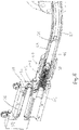
- FIGS. 1 , 2 and 3 show apparatus comprising a tool 1.
- the tool 1 is connected to a wellhead 2.
- the wellhead 2 has an annular outer wall 4 formed with a side opening 6 and a valve 8 having therethrough a passageway 10 which is aligned with the side opening 6 in the outer wall 4.
- the passageway 10 and the side opening 6 together form a lateral access passage, which provides access to the outside of the outer wall 4, the inside of the side opening 6, or the space radially inwardly of the side opening.
- the valve has a radially outer flange 9.
- the wellhead 2 has a well casing 14 disposed radially inwardly of the outer wall 4 and an annular cavity 12, known as the annulus, between the well casing 14 and the inside surface of the outer wall 4.
- the well casing 14 is supported by a casing hanger 16 which is in sealed engagement with the inside surface of the outer wall 4.
- the tool 1 is shown being used to gain access to the annular cavity 12 between the radially outer surface of the well casing 14 and the inside surface of the outer wall 4.
- it may gain access to an annulus between a radially outer surface of a production tubing and an outer wall.
- a production tubing may hang from a tubing hanger which is in sealed engagement with the inside surface of the outer wall.
- the wellhead 2 is of a standard construction.
- the valve 8 is normally a gate valve, which when closed shuts off access from the outside to the wellhead side opening 6.
- the side opening 6 includes a thread able to receive a plug.
- the plug closes the side opening and seals the annular cavity 12 from the valve 8. This can allow the valve 8 to be removed and replaced if desired.
- the valve 8 is opened and a tool is inserted through the valve passageway 10 to engage with a hexagonal head of the plug to unscrew it. The tool latches onto the hexagonal head with the aid of a circumferential groove in the head and so is able to withdraw the plug once unscrewed.
- the system also allows for the plug, or a replacement plug, to be passed along the valve passageway whilst held by the tool and then screwed into position in the side opening 6.
- the tool comprises a housing 18 formed in two parts split generally along a vertical plane in a fore and aft or axial direction of the tool. Each part of the housing 18 has a pair of laterally spaced carrier rings 20 on their respective upper surfaces, giving four carrier rings in total.
- the housing has a front wall 31 of the housing. At a rear end of the housing, a gearbox 22 is secured.
- the gearbox has an input shaft 17 to which may be connected a torque wrench.
- the gearbox is part of a screw jack, described further below.
- a Quick Test Sub (QTS) 24, of a type known in the art, is secured by a mounting plate 25 bolted to the front wall 31 of the housing.
- a guide in the form of a guide pipe 23 is secured in the QTS 24 and projects forwardly therefrom.
- the guide pipe 23 has a rear portion which is straight extending forwardly of the tool housing 18 and a front portion which is curved.
- the front portion extends through a 90° bend forwardly of the straight portion, connecting the straight portion to a connecting flange 21 provided at the forward end of the guide pipe 23.
- the bend may have other angles than 90 degrees.
- An annular recess 35 (see Figure 2 or 3 ) is provided on the front face of the connecting flange 21 for receiving a seal (not shown) for sealing between the connecting flange 21 of the tool and the radially outer flange 9 of the wellhead.
- the guide pipe 23 may be rigid or it may be made of a flexible or semi-flexible material. If the guide pipe 23 can be flexed then this may assist in positioning the tool 1 near to a wellhead in order to perform an operation.
- a torque transmitting hose 27 of an elongate transmission member extends inside the guide pipe 23 and is connected at its front end to a head portion in the form of a ferrule assembly 34.
- An example of a suitable hose 27 is Hose Specification 2440N-16V30 as supplied by the Parker Hannifin Corporation.
- the ferrule assembly 34 has at its forward end a socket 33 in which is received a plug 39, with the plug being latched in the socket 33 in a known manner.
- a longitudinally extending window 28 is provided on one side of the housing 18 .
- a ruler 37 is fastened to the outside of the housing above and adjacent to the window 28.
- a pointer 32 projects from the inside of the housing 18 through the window 28 in close proximity to the ruler 37.
- FIGS 2 , 3 , 6 , 7 and 8 show some of the internal details of the tool 1.
- the screw jack includes the gear box 22 with the input shaft 17.
- the gear box 22 has a longitudinally extending output shaft 36 formed with an external screw thread.
- the output shaft 36 is supported for rotation at its forward end by a bearing assembly 38 secured to the front wall 31 of the housing 18. It provides a rotatable drive member which when rotatably driven causes axial forward or rearward movement of a first or outer shaft 42.
- An internally threaded nut 40 (see e.g. Figure 6 ) of the screw jack engages with the external thread of the output shaft 36.
- a sleeve 41 is mounted on the nut 40 and is fixed thereto by a screw 26, which holds a forward facing annular flange of the nut axially against a rear facing annular surface of the sleeve.
- the sleeve is formed with three downwardly directed radial holes 43 in which are loosely received a castellation comprising three upward projections 47.
- the nut 40 is prevented from rotation by the interengagement of the castellation in the radial holes 47 of the sleeve 41, so that when the gearbox output shaft 36 is rotated the nut moves longitudinally along the shaft.
- the castellation is part of an axially drivable assembly 49 mounted to a rear end of the outer shaft 42.
- the assembly 49 When the assembly 49 is axially driven forwardly or rearwardly by movement of the nut 40 on the shaft 36 transmitted to the castellation 45, it causes forward or rearward movement of the shaft 42.
- An inner shaft assembly 29 extends inside the outer shaft 42 and comprises a second or inner shaft 46 and a shaft assembly nut 50.
- the outer shaft 42 is internally threaded and the shaft assembly nut 50 has an external thread engaged with the internal thread of the outer shaft 42.
- the shaft assembly nut 50 is provided on an outer surface with a pair of grooves 54 each receiving a respective plurality of balls 51 forming a ball bearing.
- Each of the pair of ball bearings 51 is engaged with each of a pair of grooves 52 formed on an internal surface of a rear portion of the inner shaft 46.
- the ball bearings prevent relative axial movement of the inner shaft 46 and the shaft assembly nut 50, but permit relative rotational movement.
- the shaft assembly nut 50 is provided with a rearwardly facing hexagonal socket 53 for receipt of a corresponding hexagonal head of an elongate tool (not shown) which may be inserted from the back of the tool 1 to rotate the shaft assembly nut 50.
- the rear end of the inner shaft 46 is provided with a rearwardly facing hexagonal socket 80 for receipt of a corresponding hexagonal head of an elongate tool (not shown) which may be inserted from the back of the tool 1 to rotate the inner shaft 46.
- the shaft assembly nut 50 has an axial bore allowing access of the tool to the socket 80 of the inner shaft 46 via the length of the nut 50.
- the hexagonal socket 53 of the nut 50 has a greater diameter than the hexagonal socket 80 of the inner shaft 46.
- the inner shaft 46 in this embodiment is a solid bolt, so as to maximise the amount of torque which it may transmit.
- it may be hollow, in order to allow fluid transmission along its length.
- the front end of the inner shaft 46 is connected in fluid tight manner to the hose 27 so as to provide a fluid transmission conduit from the front end of the inner shaft 46 to the ferrule assembly 34.
- the tool may then be used to deliver fluid via the fluid transmission conduit to or forwardly of the ferrule assembly.
- Such fluid may for example be for use in a well intervention downhole, or it may be for use locally as a sealant, for example to repair a leak between the outer wall and a well casing or oil production tubing.
- a suitable hose or pipe may be connected in fluid tight manner at its rear end.
- Figure 6 shows details of the way in which the outer shaft 42 extends out of the housing 18 in sealed manner.
- a rear portion of the QTS 24 is provided with a pair of seals (not shown) received in respective grooves 55 on an inside surface thereof, the seals engaging a smooth outer surface of the outer shaft 42.
- the seals in the grooves 55 provide a pressure tight barrier between the interior of the guide pipe 23 and the interior of the housing 18.
- the inner shaft 46 passes through a pair of seals (not shown) received in respective circumferentially extending grooves 57 on an inside surface of the outer shaft 42.
- seals in the grooves 57 provide a pressure tight barrier between the interior of the guide pipe 23 and the interior of the housing 18.
- a pressure tight barrier is provided between the interior of the guide pipe 23 and the interior of the housing 18, so that the interior of the housing 18 is not exposed to well pressure.
- connection 58 between a front end of the inner shaft 46 and a rear end of the hose 27 is of a known crimp-on type suitable for connecting a shaft to a hose.
- An example of a suitable product to form the connection 58 is crimp-on no. 1Y2LX-16-16C4462 supplied by company Parker Hannifin.
- the connection is capable of transmitting tension as well as torsion. This is so that when the inner shaft 46 is pulled rearwardly the pulling force can be transmitted to the hose 27 so that it also is pulled rearwardly.
- the connection 58 provides a fluid tight connection.
- connection 59 between the front end of the hose 27 and a rear end of the ferrule assembly 34 is the same as that described above in relation to the rear end of the hose 27.
- This connection similarly allows for tension as well as torque to be transmitted, as well as allowing fluid transmission in the embodiments having a fluid transmission conduit.
- Figure 6 shows the tool 1 in the collapsed condition.
- the outer shaft 42 is at a rearmost position
- the inner shaft assembly 29 including the inner shaft 46 and the shaft assembly nut 50 is also at a rearmost position.
- the ferrule assembly 34 projects forwardly out of the connecting flange 21 of the tool and into a radially outer part of the valve passageway 10.
- a rear part of the hose 27 occupies the straight rear portion of the guide pipe 23, and a front part of the hose occupies the curved front portion of the guide pipe.
- a suitable elongate tool (not shown) is then inserted into the rearwardly facing socket of the shaft assembly nut 50 to rotate it.
- the interengaging external thread of the nut and internal thread of the outer shaft 42 cause the nut 50 to advance forwardly.
- the plug 39 (see Figure 2 ) provided at the front of the ferrule assembly 34 is also advanced forwardly along the valve passageway 10.
- Figure 7 shows the nut 50 advanced about halfway along the length of the outer shaft 42. When the nut 50 is fully advanced in the outer shaft 42 the tool is in the intermediate condition.
- the plug 39 moves axially, and axial movement of the socket 33 at the front of the ferrule assembly 34 relative to a rear part of the ferrule assembly, which is connected to the hose 27, can be accommodated by a connection between these two components, which permits relative axial movement but not relative rotational movement.
- a head portion such as the ferrule assembly described above, may be connected directly to a forward end of the inner shaft, i.e. there may be no hose and guide therefor.
- a head portion may be configured to transmit torque to a member, for example by being formed with a socket for engaging a member in the form of a plug, and/or it may be configured to deliver fluid, such as a sealant.
- Such embodiments may be used to access the well via an access passage with the tool aligned with a radial direction of the well.
- the telescopic assembly allows the tool to fit into a relatively small amount of space.
Landscapes
- Engineering & Computer Science (AREA)
- Mechanical Engineering (AREA)
- Geology (AREA)
- Life Sciences & Earth Sciences (AREA)
- Mining & Mineral Resources (AREA)
- General Life Sciences & Earth Sciences (AREA)
- Fluid Mechanics (AREA)
- Environmental & Geological Engineering (AREA)
- Physics & Mathematics (AREA)
- Geochemistry & Mineralogy (AREA)
- General Engineering & Computer Science (AREA)
- Earth Drilling (AREA)
- Details Of Spanners, Wrenches, And Screw Drivers And Accessories (AREA)
- Manipulator (AREA)
- Transmission Devices (AREA)
- Automatic Tool Replacement In Machine Tools (AREA)
Claims (14)
- Outil (1) pour obtenir un accès latéral à un puits par l'intermédiaire d'un passage d'accès latéral (10), l'outil comprenant une partie de tête (34) et étant configuré pour faire avancer axialement vers la partie de tête (34) vers ou dans le passage d'accès latéral (10) et étant configuré pour transmettre un entraînement en rotation à la partie de tête (34) et/ou pour délivrer un fluide par l'intermédiaire d'un conduit de transmission de fluide à ou vers l'avant de la partie de tête (34), et l'outil comprenant un premier arbre (42) et un ensemble arbre (29) comprenant un second arbre (46), le second arbre (46) étant au moins partiellement reçu dans le premier arbre (42) de manière à pouvoir se déplacer axialement vers l'avant avec celui-ci, selon lequel en utilisation le mouvement axial vers l'avant des premier et second arbres provoque l'avancement vers l'avant de la partie de tête (34), et le second arbre (46) étant mobile axialement vers l'avant par rapport au premier arbre (42), caractérisé en ce que le premier arbre (42) comprenant un filetage interne et l'ensemble arbre comprenant un filetage externe prévu sur un écrou (50) de l'ensemble arbre et s'engageant dans le filetage interne du premier arbre selon lequel la rotation relative des filetages interne et externe provoque ledit mouvement axial vers l'avant du second arbre (46) par rapport au premier arbre (42) sans rotation du second arbre (46) par rapport au premier arbre (42).
- Outil selon la revendication 1, dans lequel l'écrou (50) peut entrer en rotation par rapport au second arbre (46).
- Outil selon la revendication 1 ou 2, dans lequel le second arbre (46) s'étend vers l'avant hors du premier arbre (42) de manière étanche à la pression.
- Outil selon la revendication 3, dans lequel le second arbre (46) présente une surface extérieure lisse lui permettant d'être supporté pour un mouvement axial en passant à travers un joint d'une manière étanche à la pression.
- Outil selon une quelconque revendication précédente, configuré de sorte que le premier arbre (42) peut être avancé conjointement avec le second arbre (46) et le premier arbre (42) peut être avancé par rapport au second arbre (46), dans les deux cas sans rotation du premier arbre (42) par rapport au reste de l'outil.
- Outil selon une quelconque revendication précédente, comprenant un élément de transmission allongé (27) relié au second arbre (46) pour transmettre un couple à la partie de tête (34).
- Outil selon la revendication 6, comprenant un guide (23) pour guider l'élément de transmission allongé (27) dans une trajectoire incurvée.
- Outil selon la revendication 7, dans lequel le guide (23) comprend un passage le long duquel s'étend l'élément de transmission allongé (27).
- Outil selon la revendication 8, dans lequel le passage est configuré pour être mis sous pression.
- Outil selon la revendication 7, 8 ou 9, dans lequel le guide (23) présente une courbure qui est variable.
- Outil selon l'une quelconque des revendications 7 à 10, dans lequel le guide (23) présente une partie arrière qui est droite et une partie avant qui est incurvée.
- Outil selon une quelconque revendication précédente, configuré pour transmettre un entraînement en rotation à la partie de tête (34), dans lequel la partie de tête (34) est pourvue d'une douille (33) pour mettre en rotation un élément.
- Procédé d'utilisation d'un outil (1) selon l'une quelconque des revendications 1 à 12 pour obtenir un accès latéral à un puits par l'intermédiaire d'un passage d'accès latéral (10), comprenant l'avancement vers l'avant de la partie de tête (34) vers ou dans le passage d'accès latéral (10), et la transmission de l'entraînement en rotation à la partie de tête (34) et/ou la délivrance d'un fluide à ou vers l'avant de la partie de tête (34).
- Procédé d'utilisation d'un outil (1) selon l'une quelconque des revendications 7 à 11 pour obtenir un accès latéral à un puits par l'intermédiaire d'un passage d'accès latéral (10), comprenant le guidage de l'élément de transmission allongé (27) dans une trajectoire incurvée, l'engagement de la partie de tête (34) avec un élément auquel le couple doit être transmis, l'application d'un couple à l'élément de transmission allongé (27) et la transmission du couple par l'intermédiaire de l'élément de transmission allongé (27) à la partie de tête (34) et à l'élément.
Applications Claiming Priority (2)
| Application Number | Priority Date | Filing Date | Title |
|---|---|---|---|
| GB1703297.0A GB2560170A (en) | 2017-03-01 | 2017-03-01 | Torque transmission tool |
| PCT/EP2018/055113 WO2018158402A1 (fr) | 2017-03-01 | 2018-03-01 | Outil d'accès de puits |
Publications (2)
| Publication Number | Publication Date |
|---|---|
| EP3589453A1 EP3589453A1 (fr) | 2020-01-08 |
| EP3589453B1 true EP3589453B1 (fr) | 2022-09-07 |
Family
ID=58544404
Family Applications (1)
| Application Number | Title | Priority Date | Filing Date |
|---|---|---|---|
| EP18708409.0A Active EP3589453B1 (fr) | 2017-03-01 | 2018-03-01 | Outil d'accès de puits |
Country Status (9)
| Country | Link |
|---|---|
| US (1) | US11472008B2 (fr) |
| EP (1) | EP3589453B1 (fr) |
| BR (1) | BR112019018041B1 (fr) |
| CA (1) | CA3054858A1 (fr) |
| EA (1) | EA201991847A1 (fr) |
| GB (1) | GB2560170A (fr) |
| MX (1) | MX2019010388A (fr) |
| MY (1) | MY202975A (fr) |
| WO (1) | WO2018158402A1 (fr) |
Families Citing this family (6)
| Publication number | Priority date | Publication date | Assignee | Title |
|---|---|---|---|---|
| NO344549B1 (en) * | 2018-06-13 | 2020-01-27 | Interwell Norway As | Method for replacing a chemical injection valve and an injection line plugging tool |
| CN111623192B (zh) * | 2019-02-27 | 2022-05-10 | 香港理工大学 | 管道机器人和系统 |
| CA3156005A1 (fr) * | 2019-09-25 | 2021-04-01 | Materialise N.V. | Systeme et procedes d'evaluation d'un flux de liquide et d'air |
| NO20200485A1 (en) | 2020-04-22 | 2021-10-25 | Annulus Intervention System AS | Well access apparatus and method |
| US11806844B2 (en) * | 2021-04-13 | 2023-11-07 | Snap-On Incorporated | Flexible head joints for cordless ratchet tools |
| US12392240B2 (en) * | 2022-02-28 | 2025-08-19 | Saudi Arabian Oil Company | Method for improving well integrity management for gas lift oil wells |
Citations (2)
| Publication number | Priority date | Publication date | Assignee | Title |
|---|---|---|---|---|
| US2250244A (en) * | 1938-06-17 | 1941-07-22 | Gray Tool Co | Plug inserting and removing apparatus |
| GB2480371A (en) * | 2010-05-13 | 2011-11-16 | Vetco Gray Inc | Tool and method for providing access to a wellhead annulus |
Family Cites Families (14)
| Publication number | Priority date | Publication date | Assignee | Title |
|---|---|---|---|---|
| US2501217A (en) * | 1945-10-24 | 1950-03-21 | Cleveland Pneumatic Tool Co | Adjustable drive shaft |
| US3704729A (en) * | 1971-12-21 | 1972-12-05 | Thomas Alfred Tomlinson | Plumbing device |
| US4460039A (en) * | 1982-11-04 | 1984-07-17 | W-K-M Wellhead Systems, Inc. | Wellhead valve removal and installation tool |
| US5592965A (en) * | 1994-08-11 | 1997-01-14 | Dresser Industries, Inc. | Valve stop changer |
| US6289992B1 (en) * | 1997-06-13 | 2001-09-18 | Abb Vetco Gray, Inc. | Variable pressure pump through nozzle |
| US6470971B1 (en) * | 1999-11-15 | 2002-10-29 | Abb Vetco Gray Inc. | Tubing head control and pressure monitor device |
| US20020157506A1 (en) * | 2001-04-30 | 2002-10-31 | Schade Robert L. | Flexible drive shaft |
| US20040074549A1 (en) * | 2002-10-18 | 2004-04-22 | Allen John R. | Bore plug |
| US8281818B1 (en) | 2006-02-15 | 2012-10-09 | David Vazquez | Systems and methods for gauging and controlling fluids and gases from pipes and orifices |
| GB201101467D0 (en) * | 2011-01-28 | 2011-03-16 | Cameron Int Corp | Tool |
| US9115841B2 (en) * | 2012-02-16 | 2015-08-25 | Treadstone Oilfield Services Ltd. | Apparatus for sealing a conduit |
| GB2546556B (en) * | 2016-01-25 | 2021-04-14 | Quality Intervention Tech As | Well access tool |
| GB201601324D0 (en) | 2016-01-25 | 2016-03-09 | Quality Intervention Technology As | Plug for plugging a line and a method for installing a plug in a line |
| GB2559989B (en) * | 2017-02-23 | 2021-10-13 | Quality Intervention Tech As | Well access apparatus and method |
-
2017
- 2017-03-01 GB GB1703297.0A patent/GB2560170A/en not_active Withdrawn
-
2018
- 2018-03-01 MY MYPI2019004984A patent/MY202975A/en unknown
- 2018-03-01 EP EP18708409.0A patent/EP3589453B1/fr active Active
- 2018-03-01 WO PCT/EP2018/055113 patent/WO2018158402A1/fr not_active Ceased
- 2018-03-01 BR BR112019018041-9A patent/BR112019018041B1/pt active IP Right Grant
- 2018-03-01 US US16/489,934 patent/US11472008B2/en active Active
- 2018-03-01 CA CA3054858A patent/CA3054858A1/fr active Pending
- 2018-03-01 EA EA201991847A patent/EA201991847A1/ru unknown
- 2018-03-01 MX MX2019010388A patent/MX2019010388A/es unknown
Patent Citations (2)
| Publication number | Priority date | Publication date | Assignee | Title |
|---|---|---|---|---|
| US2250244A (en) * | 1938-06-17 | 1941-07-22 | Gray Tool Co | Plug inserting and removing apparatus |
| GB2480371A (en) * | 2010-05-13 | 2011-11-16 | Vetco Gray Inc | Tool and method for providing access to a wellhead annulus |
Also Published As
| Publication number | Publication date |
|---|---|
| MY202975A (en) | 2024-05-31 |
| US11472008B2 (en) | 2022-10-18 |
| BR112019018041B1 (pt) | 2024-02-27 |
| CA3054858A1 (fr) | 2018-09-07 |
| EA201991847A1 (ru) | 2020-02-19 |
| BR112019018041A2 (pt) | 2020-04-07 |
| US20190389038A1 (en) | 2019-12-26 |
| GB201703297D0 (en) | 2017-04-12 |
| MX2019010388A (es) | 2019-12-19 |
| EP3589453A1 (fr) | 2020-01-08 |
| GB2560170A (en) | 2018-09-05 |
| WO2018158402A1 (fr) | 2018-09-07 |
Similar Documents
| Publication | Publication Date | Title |
|---|---|---|
| EP3589453B1 (fr) | Outil d'accès de puits | |
| US11313197B2 (en) | Well access tool | |
| US7473057B1 (en) | Cutting machine | |
| US8839885B2 (en) | Latching configuration for a microtunneling apparatus | |
| US11708725B2 (en) | Drill string rotation brake | |
| US11339624B2 (en) | Rotary drive actuator for an annular wellbore pressure control device | |
| US7722298B2 (en) | Hot tap machine | |
| CA3146057A1 (fr) | Graisseur de bouchon de retrait de vanne | |
| US8950478B2 (en) | Coupling between wellbore tools having central transmission shafts | |
| EA042145B1 (ru) | Приспособление для доступа к скважине | |
| EA045194B1 (ru) | Приспособление для доступа к скважине | |
| CN121854633A (zh) | 一种注脂阀及其注脂方法 | |
| GB2481848A (en) | Self sealing drill rods |
Legal Events
| Date | Code | Title | Description |
|---|---|---|---|
| STAA | Information on the status of an ep patent application or granted ep patent |
Free format text: STATUS: UNKNOWN |
|
| STAA | Information on the status of an ep patent application or granted ep patent |
Free format text: STATUS: THE INTERNATIONAL PUBLICATION HAS BEEN MADE |
|
| PUAI | Public reference made under article 153(3) epc to a published international application that has entered the european phase |
Free format text: ORIGINAL CODE: 0009012 |
|
| STAA | Information on the status of an ep patent application or granted ep patent |
Free format text: STATUS: REQUEST FOR EXAMINATION WAS MADE |
|
| 17P | Request for examination filed |
Effective date: 20190926 |
|
| AK | Designated contracting states |
Kind code of ref document: A1 Designated state(s): AL AT BE BG CH CY CZ DE DK EE ES FI FR GB GR HR HU IE IS IT LI LT LU LV MC MK MT NL NO PL PT RO RS SE SI SK SM TR |
|
| AX | Request for extension of the european patent |
Extension state: BA ME |
|
| DAV | Request for validation of the european patent (deleted) | ||
| DAX | Request for extension of the european patent (deleted) | ||
| STAA | Information on the status of an ep patent application or granted ep patent |
Free format text: STATUS: EXAMINATION IS IN PROGRESS |
|
| 17Q | First examination report despatched |
Effective date: 20210629 |
|
| GRAP | Despatch of communication of intention to grant a patent |
Free format text: ORIGINAL CODE: EPIDOSNIGR1 |
|
| STAA | Information on the status of an ep patent application or granted ep patent |
Free format text: STATUS: GRANT OF PATENT IS INTENDED |
|
| INTG | Intention to grant announced |
Effective date: 20220322 |
|
| GRAS | Grant fee paid |
Free format text: ORIGINAL CODE: EPIDOSNIGR3 |
|
| GRAA | (expected) grant |
Free format text: ORIGINAL CODE: 0009210 |
|
| STAA | Information on the status of an ep patent application or granted ep patent |
Free format text: STATUS: THE PATENT HAS BEEN GRANTED |
|
| AK | Designated contracting states |
Kind code of ref document: B1 Designated state(s): AL AT BE BG CH CY CZ DE DK EE ES FI FR GB GR HR HU IE IS IT LI LT LU LV MC MK MT NL NO PL PT RO RS SE SI SK SM TR |
|
| REG | Reference to a national code |
Ref country code: GB Ref legal event code: FG4D |
|
| REG | Reference to a national code |
Ref country code: CH Ref legal event code: EP Ref country code: AT Ref legal event code: REF Ref document number: 1516644 Country of ref document: AT Kind code of ref document: T Effective date: 20220915 |
|
| REG | Reference to a national code |
Ref country code: IE Ref legal event code: FG4D |
|
| REG | Reference to a national code |
Ref country code: DE Ref legal event code: R096 Ref document number: 602018040311 Country of ref document: DE |
|
| REG | Reference to a national code |
Ref country code: NO Ref legal event code: T2 Effective date: 20220907 |
|
| REG | Reference to a national code |
Ref country code: LT Ref legal event code: MG9D |
|
| REG | Reference to a national code |
Ref country code: NL Ref legal event code: MP Effective date: 20220907 |
|
| PG25 | Lapsed in a contracting state [announced via postgrant information from national office to epo] |
Ref country code: SE Free format text: LAPSE BECAUSE OF FAILURE TO SUBMIT A TRANSLATION OF THE DESCRIPTION OR TO PAY THE FEE WITHIN THE PRESCRIBED TIME-LIMIT Effective date: 20220907 Ref country code: RS Free format text: LAPSE BECAUSE OF FAILURE TO SUBMIT A TRANSLATION OF THE DESCRIPTION OR TO PAY THE FEE WITHIN THE PRESCRIBED TIME-LIMIT Effective date: 20220907 Ref country code: LV Free format text: LAPSE BECAUSE OF FAILURE TO SUBMIT A TRANSLATION OF THE DESCRIPTION OR TO PAY THE FEE WITHIN THE PRESCRIBED TIME-LIMIT Effective date: 20220907 Ref country code: LT Free format text: LAPSE BECAUSE OF FAILURE TO SUBMIT A TRANSLATION OF THE DESCRIPTION OR TO PAY THE FEE WITHIN THE PRESCRIBED TIME-LIMIT Effective date: 20220907 Ref country code: FI Free format text: LAPSE BECAUSE OF FAILURE TO SUBMIT A TRANSLATION OF THE DESCRIPTION OR TO PAY THE FEE WITHIN THE PRESCRIBED TIME-LIMIT Effective date: 20220907 |
|
| REG | Reference to a national code |
Ref country code: AT Ref legal event code: MK05 Ref document number: 1516644 Country of ref document: AT Kind code of ref document: T Effective date: 20220907 |
|
| PG25 | Lapsed in a contracting state [announced via postgrant information from national office to epo] |
Ref country code: HR Free format text: LAPSE BECAUSE OF FAILURE TO SUBMIT A TRANSLATION OF THE DESCRIPTION OR TO PAY THE FEE WITHIN THE PRESCRIBED TIME-LIMIT Effective date: 20220907 Ref country code: GR Free format text: LAPSE BECAUSE OF FAILURE TO SUBMIT A TRANSLATION OF THE DESCRIPTION OR TO PAY THE FEE WITHIN THE PRESCRIBED TIME-LIMIT Effective date: 20221208 |
|
| PG25 | Lapsed in a contracting state [announced via postgrant information from national office to epo] |
Ref country code: SM Free format text: LAPSE BECAUSE OF FAILURE TO SUBMIT A TRANSLATION OF THE DESCRIPTION OR TO PAY THE FEE WITHIN THE PRESCRIBED TIME-LIMIT Effective date: 20220907 Ref country code: RO Free format text: LAPSE BECAUSE OF FAILURE TO SUBMIT A TRANSLATION OF THE DESCRIPTION OR TO PAY THE FEE WITHIN THE PRESCRIBED TIME-LIMIT Effective date: 20220907 Ref country code: PT Free format text: LAPSE BECAUSE OF FAILURE TO SUBMIT A TRANSLATION OF THE DESCRIPTION OR TO PAY THE FEE WITHIN THE PRESCRIBED TIME-LIMIT Effective date: 20230109 Ref country code: ES Free format text: LAPSE BECAUSE OF FAILURE TO SUBMIT A TRANSLATION OF THE DESCRIPTION OR TO PAY THE FEE WITHIN THE PRESCRIBED TIME-LIMIT Effective date: 20220907 Ref country code: CZ Free format text: LAPSE BECAUSE OF FAILURE TO SUBMIT A TRANSLATION OF THE DESCRIPTION OR TO PAY THE FEE WITHIN THE PRESCRIBED TIME-LIMIT Effective date: 20220907 Ref country code: AT Free format text: LAPSE BECAUSE OF FAILURE TO SUBMIT A TRANSLATION OF THE DESCRIPTION OR TO PAY THE FEE WITHIN THE PRESCRIBED TIME-LIMIT Effective date: 20220907 |
|
| PG25 | Lapsed in a contracting state [announced via postgrant information from national office to epo] |
Ref country code: SK Free format text: LAPSE BECAUSE OF FAILURE TO SUBMIT A TRANSLATION OF THE DESCRIPTION OR TO PAY THE FEE WITHIN THE PRESCRIBED TIME-LIMIT Effective date: 20220907 Ref country code: PL Free format text: LAPSE BECAUSE OF FAILURE TO SUBMIT A TRANSLATION OF THE DESCRIPTION OR TO PAY THE FEE WITHIN THE PRESCRIBED TIME-LIMIT Effective date: 20220907 Ref country code: IS Free format text: LAPSE BECAUSE OF FAILURE TO SUBMIT A TRANSLATION OF THE DESCRIPTION OR TO PAY THE FEE WITHIN THE PRESCRIBED TIME-LIMIT Effective date: 20230107 Ref country code: EE Free format text: LAPSE BECAUSE OF FAILURE TO SUBMIT A TRANSLATION OF THE DESCRIPTION OR TO PAY THE FEE WITHIN THE PRESCRIBED TIME-LIMIT Effective date: 20220907 |
|
| REG | Reference to a national code |
Ref country code: DE Ref legal event code: R097 Ref document number: 602018040311 Country of ref document: DE |
|
| P01 | Opt-out of the competence of the unified patent court (upc) registered |
Effective date: 20230512 |
|
| PG25 | Lapsed in a contracting state [announced via postgrant information from national office to epo] |
Ref country code: NL Free format text: LAPSE BECAUSE OF FAILURE TO SUBMIT A TRANSLATION OF THE DESCRIPTION OR TO PAY THE FEE WITHIN THE PRESCRIBED TIME-LIMIT Effective date: 20220907 Ref country code: AL Free format text: LAPSE BECAUSE OF FAILURE TO SUBMIT A TRANSLATION OF THE DESCRIPTION OR TO PAY THE FEE WITHIN THE PRESCRIBED TIME-LIMIT Effective date: 20220907 |
|
| PLBE | No opposition filed within time limit |
Free format text: ORIGINAL CODE: 0009261 |
|
| STAA | Information on the status of an ep patent application or granted ep patent |
Free format text: STATUS: NO OPPOSITION FILED WITHIN TIME LIMIT |
|
| PG25 | Lapsed in a contracting state [announced via postgrant information from national office to epo] |
Ref country code: DK Free format text: LAPSE BECAUSE OF FAILURE TO SUBMIT A TRANSLATION OF THE DESCRIPTION OR TO PAY THE FEE WITHIN THE PRESCRIBED TIME-LIMIT Effective date: 20220907 |
|
| 26N | No opposition filed |
Effective date: 20230608 |
|
| PG25 | Lapsed in a contracting state [announced via postgrant information from national office to epo] |
Ref country code: SI Free format text: LAPSE BECAUSE OF FAILURE TO SUBMIT A TRANSLATION OF THE DESCRIPTION OR TO PAY THE FEE WITHIN THE PRESCRIBED TIME-LIMIT Effective date: 20220907 |
|
| REG | Reference to a national code |
Ref country code: DE Ref legal event code: R119 Ref document number: 602018040311 Country of ref document: DE |
|
| PG25 | Lapsed in a contracting state [announced via postgrant information from national office to epo] |
Ref country code: MC Free format text: LAPSE BECAUSE OF FAILURE TO SUBMIT A TRANSLATION OF THE DESCRIPTION OR TO PAY THE FEE WITHIN THE PRESCRIBED TIME-LIMIT Effective date: 20220907 |
|
| REG | Reference to a national code |
Ref country code: CH Ref legal event code: PL |
|
| REG | Reference to a national code |
Ref country code: BE Ref legal event code: MM Effective date: 20230331 |
|
| PG25 | Lapsed in a contracting state [announced via postgrant information from national office to epo] |
Ref country code: LU Free format text: LAPSE BECAUSE OF NON-PAYMENT OF DUE FEES Effective date: 20230301 |
|
| REG | Reference to a national code |
Ref country code: IE Ref legal event code: MM4A |
|
| PG25 | Lapsed in a contracting state [announced via postgrant information from national office to epo] |
Ref country code: LI Free format text: LAPSE BECAUSE OF NON-PAYMENT OF DUE FEES Effective date: 20230331 Ref country code: IE Free format text: LAPSE BECAUSE OF NON-PAYMENT OF DUE FEES Effective date: 20230301 Ref country code: FR Free format text: LAPSE BECAUSE OF NON-PAYMENT OF DUE FEES Effective date: 20230331 Ref country code: DE Free format text: LAPSE BECAUSE OF NON-PAYMENT OF DUE FEES Effective date: 20231003 Ref country code: CH Free format text: LAPSE BECAUSE OF NON-PAYMENT OF DUE FEES Effective date: 20230331 |
|
| PG25 | Lapsed in a contracting state [announced via postgrant information from national office to epo] |
Ref country code: BE Free format text: LAPSE BECAUSE OF NON-PAYMENT OF DUE FEES Effective date: 20230331 |
|
| PG25 | Lapsed in a contracting state [announced via postgrant information from national office to epo] |
Ref country code: IT Free format text: LAPSE BECAUSE OF FAILURE TO SUBMIT A TRANSLATION OF THE DESCRIPTION OR TO PAY THE FEE WITHIN THE PRESCRIBED TIME-LIMIT Effective date: 20220907 |
|
| PG25 | Lapsed in a contracting state [announced via postgrant information from national office to epo] |
Ref country code: BG Free format text: LAPSE BECAUSE OF FAILURE TO SUBMIT A TRANSLATION OF THE DESCRIPTION OR TO PAY THE FEE WITHIN THE PRESCRIBED TIME-LIMIT Effective date: 20220907 |
|
| PG25 | Lapsed in a contracting state [announced via postgrant information from national office to epo] |
Ref country code: BG Free format text: LAPSE BECAUSE OF FAILURE TO SUBMIT A TRANSLATION OF THE DESCRIPTION OR TO PAY THE FEE WITHIN THE PRESCRIBED TIME-LIMIT Effective date: 20220907 |
|
| REG | Reference to a national code |
Ref country code: GB Ref legal event code: 732E Free format text: REGISTERED BETWEEN 20250403 AND 20250409 |
|
| PG25 | Lapsed in a contracting state [announced via postgrant information from national office to epo] |
Ref country code: CY Free format text: LAPSE BECAUSE OF FAILURE TO SUBMIT A TRANSLATION OF THE DESCRIPTION OR TO PAY THE FEE WITHIN THE PRESCRIBED TIME-LIMIT; INVALID AB INITIO Effective date: 20180301 |
|
| PG25 | Lapsed in a contracting state [announced via postgrant information from national office to epo] |
Ref country code: HU Free format text: LAPSE BECAUSE OF FAILURE TO SUBMIT A TRANSLATION OF THE DESCRIPTION OR TO PAY THE FEE WITHIN THE PRESCRIBED TIME-LIMIT; INVALID AB INITIO Effective date: 20180301 |
|
| PG25 | Lapsed in a contracting state [announced via postgrant information from national office to epo] |
Ref country code: TR Free format text: LAPSE BECAUSE OF FAILURE TO SUBMIT A TRANSLATION OF THE DESCRIPTION OR TO PAY THE FEE WITHIN THE PRESCRIBED TIME-LIMIT Effective date: 20220907 |
|
| PGFP | Annual fee paid to national office [announced via postgrant information from national office to epo] |
Ref country code: GB Payment date: 20260106 Year of fee payment: 9 |
|
| PGFP | Annual fee paid to national office [announced via postgrant information from national office to epo] |
Ref country code: NO Payment date: 20260310 Year of fee payment: 9 |