EP3589859B1 - Frein à disque avec un dispositif de réglage et procédé pour le réglage d'une distance de dégagement d'un tel frein à disque - Google Patents
Frein à disque avec un dispositif de réglage et procédé pour le réglage d'une distance de dégagement d'un tel frein à disque Download PDFInfo
- Publication number
- EP3589859B1 EP3589859B1 EP18709514.6A EP18709514A EP3589859B1 EP 3589859 B1 EP3589859 B1 EP 3589859B1 EP 18709514 A EP18709514 A EP 18709514A EP 3589859 B1 EP3589859 B1 EP 3589859B1
- Authority
- EP
- European Patent Office
- Prior art keywords
- piston
- brake
- disc
- spindle
- adjuster
- Prior art date
- Legal status (The legal status is an assumption and is not a legal conclusion. Google has not performed a legal analysis and makes no representation as to the accuracy of the status listed.)
- Active
Links
Images









Classifications
-
- F—MECHANICAL ENGINEERING; LIGHTING; HEATING; WEAPONS; BLASTING
- F16—ENGINEERING ELEMENTS AND UNITS; GENERAL MEASURES FOR PRODUCING AND MAINTAINING EFFECTIVE FUNCTIONING OF MACHINES OR INSTALLATIONS; THERMAL INSULATION IN GENERAL
- F16D—COUPLINGS FOR TRANSMITTING ROTATION; CLUTCHES; BRAKES
- F16D65/00—Parts or details
- F16D65/38—Slack adjusters
- F16D65/72—Slack adjusters hydraulic
- F16D65/74—Slack adjusters hydraulic self-acting in one direction
-
- F—MECHANICAL ENGINEERING; LIGHTING; HEATING; WEAPONS; BLASTING
- F16—ENGINEERING ELEMENTS AND UNITS; GENERAL MEASURES FOR PRODUCING AND MAINTAINING EFFECTIVE FUNCTIONING OF MACHINES OR INSTALLATIONS; THERMAL INSULATION IN GENERAL
- F16D—COUPLINGS FOR TRANSMITTING ROTATION; CLUTCHES; BRAKES
- F16D65/00—Parts or details
- F16D65/38—Slack adjusters
- F16D65/40—Slack adjusters mechanical
- F16D65/52—Slack adjusters mechanical self-acting in one direction for adjusting excessive play
- F16D65/56—Slack adjusters mechanical self-acting in one direction for adjusting excessive play with screw-thread and nut
- F16D65/567—Slack adjusters mechanical self-acting in one direction for adjusting excessive play with screw-thread and nut for mounting on a disc brake
-
- F—MECHANICAL ENGINEERING; LIGHTING; HEATING; WEAPONS; BLASTING
- F16—ENGINEERING ELEMENTS AND UNITS; GENERAL MEASURES FOR PRODUCING AND MAINTAINING EFFECTIVE FUNCTIONING OF MACHINES OR INSTALLATIONS; THERMAL INSULATION IN GENERAL
- F16D—COUPLINGS FOR TRANSMITTING ROTATION; CLUTCHES; BRAKES
- F16D2129/00—Type of operation source for auxiliary mechanisms
- F16D2129/02—Fluid-pressure
Definitions
- the invention relates to a disc brake with an adjusting device according to the preamble of claim 1.
- the invention also relates to a method for adjusting a clearance of such a disc brake.
- Vehicles especially motor vehicles, are equipped with friction brakes in order to convert kinetic energy.
- the disc brake is particularly preferred in the passenger car and commercial vehicle sectors.
- Pneumatically operated disc brakes are now standard equipment in heavy commercial vehicles.
- a disc brake In the typical design of a disc brake, it consists of a brake caliper including internal mechanics, usually two brake pads and the brake disc.
- the cylinder forces are introduced to the internal mechanics via a pneumatically operated cylinder, amplified by an eccentric mechanism and transferred as a clamping force, e.g. via threaded spindles, to the brake linings and brake discs, whereby the wear on the brake disc and brake linings is compensated for via the threaded spindles, for example.
- the application forces act on the brake disc via both brake linings. Since the pads are designed as wearing parts, they are generally softer than the brake disc, i.e. the pads experience a change in pad thickness over their service life, they wear out. The brake disc can also wear out. This wear makes it necessary for a wear readjustment to compensate for the changes caused by the wear and to re-establish a previously determined clearance, which is also referred to as the nominal clearance.
- Such disc brakes are therefore equipped with an automatically acting wear adjuster to compensate for lining wear.
- These purely mechanically acting wear adjusters only have one direction of action. This means that the lining wear, which occurs during the operating time, is compensated.
- the adjuster is therefore able to compensate for excessive clearance by means of an infeed movement.
- the clearance is the gap between the brake linings and the brake disc in the non-actuated state. A correctly set clearance is very important for the safe operation of the brake.
- a change in the clearance can also be caused by other effects. As already described above, an increase in the clearance can result from the occurrence of lining wear. Another possibility for changing the clearance results from the vibration stress on the brake in practical vehicle use. There there can be both an increase and a decrease in the clearance.
- the so-called waxing of the covering can lead to a reduction in the air gap.
- the friction lining takes on the thickness before the high pressure load with a time delay and thus causes a reduction in the clearance.
- a dynamically induced increase in the clearance can be compensated for by the wear adjuster and therefore does not pose a particular problem for safe operation of the brake.
- the readjusters currently used in pneumatically operated disc brakes are systems that are activated when the brake is operated by the brake lever or by a similar component required to generate the application force. The readjustment process therefore takes place as a function of the brake actuation.
- a typical feature of these adjustment systems is the asymptotic mode of operation. This means that the adjustment travel depends on the size of the clearance deviation.
- the readjustment step per actuation is generally between 10 and 20% of the clearance deviation. If there is a large deviation, a larger adjustment step takes place, while if there is a small deviation, a correspondingly smaller adjustment step takes place.
- a clearance correction in a single step is not possible with these adjustment concepts. Furthermore, a clearance correction from a value that is too small to a larger value can hardly or only with great difficulty be implemented with these adjuster concepts.
- Another adjustment concept is an adjustment that is decoupled from the actuation of the brake.
- the readjustment does not take place during a brake actuation but rather independently between the brake actuations, preferably as a function of the clearance situation, for example EP 1 546 571 B1 describes.
- a separate actuator and a separate energy supply eg compressed air
- this system is characterized by a single-stage mode of operation. This means that the clearance deviation is compensated for by a single readjustment step.
- Movement compensates for the play in the screw drive.
- the size of the constructive clearance is defined by the thread play. If the clearance is too large, the adjusting piston is pushed further in the direction of the brake disc, since the clearance in the screw drive has now been overcome, the self-locking design of the screw drive causes the adjusting spindle to rotate and the clearance to be corrected. The subsequent venting of the adjusting piston allows it to return to its rest position. The adjusting spindle is also brought into its rest position by means of a piston seal and the so-called "pull back" effect within the thread play, thereby adjusting the constructive clearance.
- this system has the advantage that it is possible, for example, to design a pneumatically actuated fixed caliper that is also equipped with such an adjustment device on the reaction side (rim side) (see EP 1 546 571 B1 ).
- the object of the present invention is therefore to create an improved adjusting device which eliminates or at least significantly prevents the above-mentioned disadvantages.
- Another object is to provide an improved method for setting a clearance for a disc brake.
- a disc brake according to the invention preferably actuated by compressed air, in particular for a motor vehicle, comprises a brake disc, a brake caliper overlapping the brake disc, in which an application device is arranged, with a brake lining being provided on both sides of the brake disc, and an adjustment device with at least one adjustment device for adjustment of friction surface wear on brake linings and brake disc, the at least one adjustment device being operable with a pressure medium independently of the application device.
- the at least one adjustment device is designed with a first cylinder unit with a first pressure piston and with a second cylinder unit with a second pressure piston, the The second pressure piston of the second cylinder unit has a piston which is in contact with the brake lining and an adjusting piston which is arranged on the piston.
- the adjustment function is divided into two different task steps.
- the first task step is the adjustment of the air gap, i.e. the setting of a previously determined air gap as the nominal air gap.
- the first cylinder unit is provided for this purpose.
- the second cylinder unit is used for adjustment in a second task step.
- the adjustment device thus acts in both directions, too large and too small ventilation clearances can be corrected.
- the clearance correction and the reset to the previously determined clearance takes place in one stage and immediately after the adjustment device has been activated. An advantageously rapid correction is made possible.
- a stroke of the first pressure piston of the first cylinder unit corresponds to a previously determined clearance of the disc brake.
- this nominal air clearance is structurally integrated in the adjustment device and also serves as a reference variable at the same time.
- the at least one adjustment device comprises a stationary housing with an inner bore, a spindle head, a spindle, a piston, an adjustment piston and a sealing washer. This enables a compact structure that ensures easy installation.
- the stationary housing of the at least one rear adjustment device can alternatively also be a back section of the brake caliper, the inner bore being formed in the back section. This results in a space-saving structure.
- the advantage of a particularly compact structure is made possible by the design in which the first cylinder unit and the second cylinder unit are arranged in series in the housing and are separated by the sealing washer or by a fixed intermediate base.
- the sealing washer or the fixed intermediate floor divides the inner bore of the housing into a substantially closed space between the sealing washer or the fixed intermediate floor and a bottom wall of the housing and into an open space between the sealing washer and an opening in the inner bore facing the brake disc, wherein the sealing disk is sealed against the inner bore by means of a sealing element on its outer circumference.
- the first cylinder unit has the closed space and the spindle head as the first pressure piston, wherein the spindle head is connected to the spindle, and wherein the spindle in the second cylinder unit is in engagement with the second pressure piston.
- the spindle head is provided with an outer cone pointing towards the bottom wall of the housing or another outer contour, with an inner cone or a mating contour corresponding to the other outer contour being arranged on the inner side of the bottom wall, which is arranged with the outer cone or with communicates with the other outer contour of the spindle head. This makes it possible to achieve an end position in which the outer cone and the inner cone are in engagement.
- Another embodiment provides that an area between the outer cone or the other outer contour of the spindle head and the inner cone or the mating contour of the housing is sealed against the inner wall of the housing by means of a sealing element on the outer circumference of the spindle head and forms a pressure chamber of the first cylinder unit, which communicates with a connection for a print medium. In this way, a pressure medium can be applied to the first cylinder unit in a simple manner.
- the spindle head is the first pressure piston of the first cylinder unit together with the spindle in the direction of an adjuster axis from a rest position of the adjuster, in which the spindle head with its outer cone or its other outer contour is in contact with the inner cone or the mating contour of the housing a working end position, which is determined by the sealing washer, and designed to be longitudinally displaceable back, this stroke of the spindle head corresponding to the previously defined clearance.
- the nominal air clearance is structurally integrated in the adjustment device. It is possible that the nominal clearance, e.g. by changing the position or thickness of the sealing washer or e.g. by changing the longitudinal extension of the spindle head, can be given different dimensions to adapt to different conditions.
- the spindle head of the first cylinder unit is designed to be rotatable together with the spindle about the adjuster axis, with the spindle head being rotatable with the spindle in the rest position due to a high friction torque between the outer cone or the other outer contour of the spindle head and the Inner cone or the mating contour is blocked.
- the rotatability of the spindle head and spindle is advantageously simply dependent on the position of the spindle head.
- the spindle head is supported by an axial roller bearing via a return spring on the sealing disk, the return spring exerting an axial force in the direction of the adjuster axis on the spindle head in such a way that the spindle head is pressed into the rest position in which its outer cone or its other The outer contour rests firmly on the inner cone or the mating contour of the housing.
- the roller bearing enables the spindle head and spindle to be rotated with little friction.
- the return spring advantageously has three functions, namely the support of the roller bearing, the return of the spindle head and spindle to the rest position and an increase in the frictional torque of the outer cone of the spindle head and the inner cone of the housing in the rest position by the axial spring force.
- the return spring and the axial roller bearing can also be represented as independent components. The space requirement is somewhat larger in this version compared to the previously described solution.
- the spindle head has a guide section which extends through a through-hole in the sealing disk or the intermediate floor and forms a bearing and axial guide for the spindle head on the sealing disk or on the intermediate floor, with a sealing element between the sealing disk or intermediate floor and the guide section is provided.
- the spindle head has at least one axial channel as an overflow channel, which connects the pressure chamber of the first cylinder unit with a pressure chamber of the second cylinder unit.
- the second cylinder unit comprises the open space, the piston and the adjusting piston as a second pressure piston, the piston and the adjusting piston being arranged longitudinally displaceably in the open space in the inner bore, and wherein the piston can also be rotated.
- the two pistons enable the adjustment device to be reset, e.g. when the brake lining is changed, whereby one piston can be rotated from the outside and the adjustment piston cannot be rotated. This achieves a multiple function with little space requirement.
- the pressure chamber of the second cylinder unit is fixed in the inner bore between end sections of the piston and the adjusting piston and the sealing washer or the intermediate base. It can communicate with the first pressure chamber in a simple manner through the overflow channel of the spindle head and can be acted upon with pressure medium from there.
- the piston is arranged in a through-hole of the adjusting piston coaxially to the adjusting piston and to the adjusting axis, the adjusting piston being axially fixed on the piston and being sealed off from it with a sealing element, and the piston being rotatable with respect to the adjusting piston about the adjusting axis , wherein the adjusting piston is sealed against the inner bore of the housing by a sealing element.
- At least one friction spring is provided between the piston and the adjusting piston, by means of which a frictional torque that can be influenced is generated between the piston and the adjusting piston.
- the piston can advantageously be rotated manually after the frictional torque has been overcome, without it being rotated during normal operation.
- the adjusting piston is secured against rotation relative to the stationary housing by at least one or more guide elements designed as sliding blocks. This is for the function of the readjustment is important, and at the same time the piston can be rotated in the readjustment piston during manual reset.
- the spindle is designed as a threaded spindle with an external thread, extends through the internal bore of the housing and is in engagement with the piston via its external thread with an internal thread of the piston.
- An advantageous coupling of the cylinder units can thus be made possible, the spindle being screwed into the piston.
- a longitudinal movement of the piston can be converted into a rotary movement of the spindle by means of the thread.
- a rotary movement of the spindle enables a longitudinal adjustment of the spindle relative to the piston. In this way, it can advantageously be achieved that an excessively large clearance can be reduced and an excessively small clearance can be increased.
- the influence of the thread play on the accuracy of the clearance can advantageously be avoided if a prestressing spring is provided between the spindle and the piston, by means of which the external thread of the spindle is axially prestressed relative to the internal thread of the piston.
- the internal thread of the piston extends from an end section of the piston facing the sealing disk in the direction of the brake disk and opens into an axial bore, the axial bore being closed pressure-tight with a sealing cap or by another sealing method.
- the pressure chamber of the second cylinder unit is sealed off from the atmosphere in the area of the thread engagement of the spindle and piston.
- a sealing effect can be achieved by a press fit or with the help of a sealing ring.
- the axial securing of the sealing cap can be achieved by a locking ring.
- the pressure chamber of the second cylinder unit is sealed off from the atmosphere by the sealing element between the piston and the adjusting piston, by the sealing element between the adjusting piston and the inner bore of the housing and by the sealing cap in the axial bore of the piston, as this is the case can advantageously avoid pressure losses in the pressure medium.
- the piston is in contact with the brake lining via a pressure section, the pressure section having a circumferential collar with a profile as a force application for a manual reset by rotating the piston.
- the profiling is used advantageously for attaching a suitable tool.
- the excessively large clearance is reduced in method step S4, in that a spindle which is axially blocked in the working end position by the spindle head connected to it is moved by the movement of the piston and the adjusting piston through a self-locking thread engagement between the spindle and the piston
- the adjuster axle rotates until the piston and the adjuster piston have brought the brake lining to rest on the brake disc.
- the release play that is structurally predetermined in the first cylinder unit is used as a reference value in such a way that the spindle is axially blocked in the end working position of the first cylinder unit, i.e. after the predetermined release clearance has passed.
- Another embodiment of the method provides that, in method step S6, the excessively small clearance is increased by adjusting a spindle that is axially adjustable in the intermediate position by the movement of the spindle head connected to it and rotating due to the threaded engagement of the spindle and the blocked piston until the spindle head reaches the working end position.
- the advantage of the self-locking thread engagement between the piston and spindle is used to adjust the rotating spindle axially and thus to increase the too small clearance.
- the release play that is structurally predetermined in the first cylinder unit is also used here as a reference value, in that the spindle head has not yet reached the end-of-work position, i.e. has not yet fully passed through the complete, previously defined release clearance.
- the spindle head in process steps S3, S5 and S7, is returned to the rest position by means of a return spring after venting from the end-of-work position, the release clearance previously determined by the design in the first cylinder unit being set again.
- the release play that has been structurally predetermined in the first cylinder unit is set in that the spindle head completely passes through the previously defined release play from the working end position to the rest position and thus the adjusting piston of the spindle, which is connected to the spindle head, adjusts the brake lining to the nominal release play .
- FIG. 1 is a schematic perspective view of an embodiment of a disc brake 1 according to the invention with an adjusting device according to the invention.
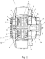
- Fig. 2 shows a schematic plan view of the disc brake 1 according to FIG Fig. 1 .
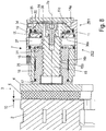
- Fig. 3 and Fig. 4 represent schematic partial sectional views of the disc brake 1 Fig. 1 represent.
- Fig. 5 shows a schematic sectional view of an adjusting device 7 of the adjusting device according to the invention Fig. 3-4 .
- the disc brake 1 has a brake disc 2 with a brake disc axis 2a.
- a brake lining 3, 3 ' is arranged on both sides of the brake disc 2.
- Each brake lining 3, 3 ' has a lining carrier plate 4, 4', on each of which a friction lining 5, 5 'is applied.
- the brake linings 3, 3 ' are received in a manner not described further in a brake caliper 6 so as to be displaceably guided in the direction of the brake disk axis of rotation 2a.
- the brake disc 2 is overlapped by the brake caliper 6, which is designed here as a fixed caliper, and is designed to be displaceable on a wheel axle, not shown here.
- the brake caliper 6 has an application section 6a and a back section 6b and is attached to a brake carrier (not designated).
- a fixed saddle is, for example, in the EP 1 546 571 B1 described, so it is not discussed in more detail here.
- the brake lining 3 located next to the application section 6a of the brake caliper 6 is called the application-side brake lining 3 and the brake lining 3 'arranged on the back section 6b of the brake caliper 6 is called the rear-side or reaction-side brake lining 3'.
- the side of the disc brake 1 with the application section 6a is referred to as the application side ZS, the side of the disc brake 1 with the back section 6b being called the rim side FS here.
- Fig. 3 shows a partial sectional view of the disc brake 1 according to FIG Fig. 2 in a top view.
- the cutting plane here runs parallel to the plane of the drawing Fig. 3 from the rim side FS to the application side ZS of the disc brake 1 in the longitudinal direction of the brake disc axis of rotation 2a through the brake caliper 6 and part of the adjusting device arranged in the brake caliper 6.
- the adjustment device is provided to compensate for the wear of the brake linings 3, 3 'and the brake disc 2 and for this purpose has four adjustment devices 7, 7' in this embodiment, two of which are assigned to a brake lining 3, 3 '.
- Two adjustment devices 7 on the application side are assigned to the brake lining 3 on the application side and are arranged parallel to one another in the application section 6a of the brake caliper 6. This is explained further below.
- Each of the adjustment devices 7 on the application side has an adjustment axis 7a.
- two rear adjusting devices 7 ' each of which has an adjusting axis 7'a, are arranged parallel to one another in the back section 6b of the brake caliper 6 and are assigned to the rear brake lining 3'.
- the tensioning-side adjustment devices 7 are here arranged opposite the rear-side adjustment devices 7 'in such a way that their respective adjustment axes 7a and 7'a are aligned with one another.
- the adjuster axes 7a, 7'a all lie in a common plane and also run parallel to the brake disk axis of rotation 2a.
- FIG. 13 is another partial sectional view of the disc brake 1 according to FIG Fig. 1 shown from the side.
- the cutting plane here runs perpendicular to the plane of the drawing Fig. 4 from the rim side FS to the application side ZS of the disc brake 1 through a plane of the adjuster axles 7a, 7'a of the in Fig. 3 not cut, ie in Fig. 3 adjusting devices 7, 7 'arranged below.
- An application device ZV is installed in the application section 6a of the brake caliper 6 and has a rotary brake lever which is not described in detail here. Part of the brake lever is in Fig. 3 in a longitudinal section and in Fig. 4 indicated in a cross section as a clamping device ZV.
- the rotary brake lever can be actuated, for example, by a pneumatic brake cylinder (not shown) which is fastened to a flange 6c of the application section 6a.
- the application-side brake lining 3 is in contact with a pressure side 4a of its lining carrier plate 4 with the application-side adjustment devices 7 via a pressure section 17 in each case.
- the pressure sections 17 are attached here to the ends of a piston 16 of each adjustment device 7 on the application side.
- the other, rear brake pad 3 ' is in in a similar manner, with a pressure side of its lining carrier plate 4 ', in contact with the rear-side adjustment devices 7' via a pressure section 17 'each.
- These pressure sections 17 ' are also attached to the ends of a piston 16 of each rear adjuster 7'.
- the pressure sections 17, 17 ' are formed in one piece with the piston 16 here, but can also be separate pressure pieces.
- the application-side adjustment devices 7 are each in contact with the application device ZV with a pressure plate 12 at their application-side ends, which are opposite the ends facing the brake disc 2.
- a spring not designated, is provided here, which moves the application-side adjustment devices 7 with the application device ZV into the position shown in FIG Fig. 3 and Fig. 4
- the shown released position of the disc brake 1 is reset when the disc brake 1 is not applied.
- the rear adjustment devices 7 ' are received in corresponding receptacles in the back section 6b of the brake caliper 6 and are supported in the back section 6b. This is described in more detail below.
- the adjustment devices 7 on the application side are inserted in the application section 6 a of the brake caliper 6 with a housing 11.
- the housing 11 is in the application section 6a with at least one connecting element 13, which is in grooves 11d of the housing 11 (see also Fig. 7 ) engages, secured against twisting.
- the housing 11 is described in detail below.
- the associated application force is transmitted from the application device ZV to the pressure plate 12 of the adjustment devices 7 on the application side and to the housing 11 thereof.
- the housings 11 act on an outer cone 14a of a respective spindle head 14 via inner cone 11c, which is firmly connected to a spindle 15 in each case.
- the application force is thus transmitted via the spindle heads 14 to the spindles 15, which each have an external thread 15b with an internal thread 16b (see Fig. 5 ) of the associated piston 16 are in engagement.
- the application force is passed on to the pistons 16 and their pressure sections 17 and applied by them to the brake lining 3 on the application side.
- the adjustment devices 7 on the application side are located in the force curve of the application force.
- the housing 11 instead of the inner cone 11c, the housing 11 then has a counter-contour corresponding to the other outer contour of the spindle head 14.
- the adjustment devices 7 'on the rear side do not have a housing here.
- the housing is formed here by the back section 6b of the brake caliper 6. This makes it possible that an overall size of the brake caliper 6 can be reduced.
- the rear adjustment devices 7 ′ are inserted into matching recesses in the back section 6 b of the brake caliper 6. These indentations are designed with inner cones 6d.
- the spindle heads 14 of the rear adjustment devices 7 ' are each connected to a spindle 15, which in turn is connected to the respective piston 16 and its associated pressure section 17' via the thread engagement described above.
- the reaction force is applied to the rear brake lining 3 'by the rear adjustment devices 7' when the brake is applied.
- the rear adjustment devices 7 ' are located in the force curve of the reaction force generated on the application force.
- the rear-side adjustment devices 7 ′ like the application-side adjustment devices 7, are equipped with a housing 11.
- the indentations of the back section 6b of the brake caliper 6 are formed in accordance with the outer shape of the housing 11.
- FIG. 11 is a schematic sectional view of an adjustment device 7 on the application side of the adjustment device according to the invention Fig. 3-4 shown.
- the air gap 10 is structurally stipulated in advance as a so-called "nominal air gap" to a certain level.
- this clearance 10 becomes larger. If this is not compensated for, the disk brake 1 cannot achieve its peak performance, since an actuation stroke of the application device ZV is increased.
- the readjusting device according to the invention with the readjusting devices 7, 7 ' is designed to readjust the previously established air gap 10, that is to say the nominal air gap.
- readjustment here is to be understood as a readjustment of the previously established ventilation clearance 10 (nominal ventilation clearance) if the current ventilation clearance has a dimension that is not equal to the previously established ventilation clearance 10.
- readjustment is to be understood here to mean both a reduction in the air gap and an increase in the air gap of the respective current air gap.
- the previously determined clearance 10 can change not only due to wear of the brake linings 3, 3 'and the brake disc 2, but also for other reasons, such as the effects of vibrations.
- the previously defined clearance 10 is set again by reducing an excessively large clearance. And in the case of the increase in the air gap, the previously defined air gap 10 is set back to the previously defined air gap 10 by increasing an existing air gap that is too small.
- the previously established clearance is structurally established in the adjusting device 7, 7 '.
- the previously determined clearance 10 corresponds to the stroke of a pressure piston between two stops. These stops can of course also be designed to be adjustable and / or adjustable in order to be adaptable to different nominal air clearances.
- the adjusting device reduces an existing clearance if it is too large in relation to the clearance 10 previously defined or stored in the adjusting devices 7, 7 ', and it increases an existing clearance if this is too large in relation to the clearance 10 in the adjusting devices 7, 7' Adjusting devices 7, 7 'previously defined or stored clearance 10 is too small.
- the brake linings 3, 3 ' may come into light contact with the brake disk 2 either partially or completely, which causes what is known as a grinding torque. This can cause increased wear of the brake disc 2 and brake pads 3, 3 'and thus an additional burden on the environment, in particular due to fine dust, as well as increased fuel consumption of the vehicle with this brake, since the grinding torque also generates a certain braking effect.
- Process step 1 is the setting of the clearance 10 and process step 2 is the readjustment. This is described in more detail below.
- the adjustment mechanism of the adjustment devices 7, 7 ′ is activated with the aid of a pressure medium, preferably compressed air, with which two cylinder units ZE1, ZE2 are acted upon via a connection 8 and pressure line 9.
- the pressure line 9 connects the common connection 8 with a connection 8 'of the rear adjustment device (s) 7' (see Fig. 1 , 2 ) on the back section 6b of the brake caliper 6.
- the adjustment device 7 comprises a stationary housing 11, a spindle head 14, a spindle 15, a piston 16, an adjustment piston 18 and a sealing disk 19.
- the housing 11 is designed as a hollow cylinder with a circular cross-section and inserted in the brake caliper 6, here in the application section 6a, in a stationary and rotationally fixed manner.
- An inner bore 11b of the housing 11 is open facing the brake disc 2, runs in the longitudinal direction of the housing 11 in the direction of the adjuster axis 7a to the application side ZS (in Fig. 5 to the right) up to a shoulder 11e and then with a smaller inner diameter further to a further shoulder of an inner cone, which is closed with a bottom wall 11f.
- the bottom wall 11f is connected on the outside to the pressure plate 12 and runs parallel to the brake disk 2.
- the inner bore 11b is divided into the two cylinder units ZE1 and ZE2 by the sealing washer 19 inserted into it, which rests against the shoulder 11e.
- the first cylinder unit ZE1 and the second cylinder unit ZE2 are arranged in series in the housing 11.
- the first cylinder unit ZE1 is arranged between the sealing disk 19 and the bottom wall 11f of the housing 11, whereas the second cylinder unit ZE2 is arranged between the sealing disk 19 and the opening of the inner bore 11b facing the brake disk 2.
- the first cylinder unit ZE1 has the spindle head 14 as the first pressure piston, the spindle head 14 being firmly connected to the spindle 15.
- the spindle 15 can be viewed as a piston rod. It extends through the second cylinder unit ZE2, which has the second pressure piston, namely the piston 16 and the adjusting piston 18, as will be explained in more detail below.
- the piston 16, the adjusting piston 18 with a sealing element 26a and the spindle 15 are referred to as an adjusting unit.
- the sealing washer 19 is fixed axially against the shoulder 11e in the inner bore 11b with a locking ring 32. In this way, the sealing disk 19 divides the inner bore 11b into a substantially closed space between the sealing disk 19 and the bottom wall 11f and into an open space between the sealing disk 19 and the opening of the inner bore 11b facing the brake disk 2.
- the sealing disk 19 is sealed with a sealing element 28, for example an O-ring, with respect to the circumferential wall of the inner bore 11b.
- a sealing element 28 for example an O-ring
- the sealing disk 19 is provided with a through-hole 19a for a guide section 14c of the spindle head 14.
- the first cylinder unit ZE1 has the closed space between the sealing disk 19, the bottom wall 11f and the circumferential wall of the housing 11 and the spindle head 14.
- the spindle head 14 is arranged in this space so as to be longitudinally displaceable in the direction of the adjuster axis 7a and rotatable about the adjuster axis 7a.
- the spindle head 14 has an outer cone 14a on the clamping side, a circumferential edge section 14b with a sealing element 27, a guide section 14c, and a bearing section 14d.
- the outer cone 14a of the spindle head 14 is designed as a truncated cone and communicates with its outer conical surface with an inner conical surface of the inner cone 11c.
- the edge section 14b makes contact with the circumferential inner wall of the housing 11 in the area between the sealing washer 19 and the inner cone 11c.
- An area between the outer cone 14a and the inner cone 11c is sealed off from the inner wall of the housing 11 by means of the sealing element 27 on the outer circumference of the spindle head 14. This area forms a pressure chamber 35 of the first cylinder unit ZE1.
- a connection bore 34 is formed from the outside of the cylinder wall of the housing 11 running through the inner cone 11c and communicates with the pressure chamber 35 of the first cylinder unit ZE1.
- the side of the spindle head 14 facing the sealing washer 19 is provided with a circumferential recess which forms the bearing section 14d.
- a circumferential groove is formed as a bearing seat 14e, in which an axial roller bearing 30 is received with little friction.
- the axial roller bearing 30 is supported by a return spring 30a on the sealing washer 19 on its application-side side. In this way, the return spring 30a presses the axial roller bearing 30 against the spindle head 14.
- the return spring 30a exerts an axial force in the direction of the adjuster axis 7a, 7'a on the spindle head 14 in such a way that the spindle head 14 moves from the return spring into the rest position is pressed, in which its outer cone 14a rests firmly against the inner cone 11c.
- the conical spindle head 14 is thus supported in the rest position on the corresponding, non-rotatable counter-contour, which is formed by the inner cone 14a, on the housing 11.
- the guide section 14c of the spindle head 14 protrudes in the direction of the brake disk 2 and extends through the through hole 19a of the sealing disk 19. This forms a bearing and axial guide for the spindle head 14 on the sealing disk 19.
- a sealing element 29 seals the guide section 14c at its outer diameter with respect to the through hole 19b of the sealing disk 19.
- the outside diameter of the guide section 14c here corresponds to approximately half the outer diameter of the edge section 14b of the spindle head 14.
- the spindle head 14 By mounting the roller bearing 30 and the guide section 14c in the through hole 19a of the sealing disk 19, the spindle head 14 (and of course the spindle 15 firmly connected to it) can also be rotated about the adjuster axis 7a, 7'a. In the rest position, however, the spindle head 14 is non-rotatable due to the contact between its outer cone 14a and the inner cone 11c and the axially acting force of the return spring 30a due to the frictional torque acting therewith.
- the first cylinder unit ZE1 thus comprises the first pressure piston as a spindle head 14 with an outer cone 14a, the space surrounded by the housing 11 between the sealing disk 19 and the inner cone 11c of the housing 11, the roller bearing 30 and the return spring 30a.
- a displacement of the spindle head 14 is part of the space surrounded by the housing 11 between the sealing disk 19 and the inner cone 11c of the housing 11.
- the stroke of the spindle head 14 is limited by the sealing washer 19 and the inner cone 11c and in this way corresponds to the previously structurally defined clearance 10, namely the nominal clearance.
- the spindle head 14, which forms the first pressure piston, is used to adjust the clearance.
- This means that the nominal clearance is determined by the stroke of the spindle head 14 and forms a reference variable with which it is possible to correctly set the previously determined clearance 10 reproducibly after each change. This is explained in more detail below.
- the second cylinder unit ZE2 takes on the adjustment function, i.e. the pressing of the adjustment unit (spindle 15, piston 16 and adjustment piston 18) against the respective brake lining 3, 3 ′ and thus against the brake disc 2.
- a central section of the spindle head 14 has a fastening section 23 and at least one axial channel as an overflow channel 36.
- the at least one overflow channel 36 connects the pressure chamber 35 of the first cylinder unit ZE1 with a pressure chamber 37 of the second cylinder unit ZE2.
- the spindle head 14 is fixedly but detachably connected to the spindle 15 via the fastening section 23 by means of a fastening element 24, for example a screw.
- a fastening element 24 for example a screw.
- the clamping-side end of the spindle 15 has a profiled projection 15a which engages with a corresponding guide section 23a of the fastening section 23.
- the spindle 15 is designed here as a threaded spindle with an external thread 15b and extends from the sealing disk 19 in the direction of the brake disk 2 through the inner bore 11b of the housing 11 and protrudes therefrom.
- the spindle 15, together with the spindle head 14 fixedly connected to it, is arranged to be axially displaceable in the direction of the adjuster axis 7a and rotatable about the adjuster axis 7a.
- the displaceability of the spindle 15 is limited by the stroke of the spindle head 14 in the first cylinder unit ZE1.
- the rotatability of the spindle 15 and spindle head 14 is blocked in the rest position of the adjustment device 7, 7 ', as already indicated above, due to the high frictional torque between the outer cone 14a and the inner cone 11c.
- the second cylinder unit ZE2 comprises the open space, the piston 16 and the adjusting piston 18, which together form a common pressure piston of the second cylinder unit ZE2, namely the second pressure piston.
- the piston 16 and the adjusting piston 18 can be displaced in the open space in the inner bore 11b and can be rotated about the adjusting axis 7a.
- the piston 16 is arranged in a through hole 18f of the adjusting piston 18 coaxially to the latter and to the adjusting axis 7a, the adjusting piston 18 being axially fixed on the piston 16, and the piston 16 being rotatable relative to the adjusting piston 18 about the adjusting axis 7a.
- the piston 16 and the adjusting piston 18 are connected in such a way that they can jointly be displaced axially in the direction of the adjusting axis 7a.
- the pressure chamber 37 of the second cylinder unit ZE2 is defined between the end sections of the piston 16 and the adjusting piston 18, the wall of the housing 11 surrounding them and the side of the sealing disk 19 facing the brake disk 2.
- the piston 16 is designed as a threaded piston with an internal thread 16b.
- the internal thread 16b communicates with the external thread 15b of the spindle 15.
- the piston 16 is screwed onto the spindle 15, its internal thread 16b engaging with the external thread 15b of the spindle 15.
- Internal thread 16b and external thread 15b are designed as non-self-locking threads.
- the internal thread 16b of the piston 16 extends from an application-side end section 16a of the piston 16 in the direction of the brake disc 2 over about four fifths of the length of the piston 16 in the direction of the adjustment axis 7a and opens into an axial bore 16d in an end area facing the brake disc 2 of the piston.
- the bore 16d and thus the adjustment unit with spindle 15, piston 16 and adjustment piston 18 are closed in a pressure-tight manner with a sealing cap 22.
- a sealing effect can be achieved by a press fit of the sealing cap 22 in the bore 16d (as shown in the figure) or with the aid of a sealing ring.
- the axial securing of the sealing cap 22 can be achieved by a locking ring.
- An alternative solution to this would be a screwed-in sealing cap 22. In principle, however, other sealing and securing methods known from technology are also possible (e.g. welding, gluing, etc.).
- the end region of the piston 16 facing the brake disk 2 is provided with the pressure section 17, which is in contact with the pressure side 4a of the brake lining 3 on the application side by a pressure surface 17a facing the brake disk 2.
- the pressure section 17 is provided with a circumferential collar 17b which protrudes radially from an outer surface 16c of the piston 16 and forms a stop for the adjusting piston 18, which is pushed onto the piston 16.
- a sealing element 26 is used which, in addition to the circumferential collar 17b of the pressure section 17 in a circumferential groove in the Outer surface 16c of the piston 16 is inserted.
- the adjusting piston 18 is pushed onto the piston 16 before the piston 16 is screwed on.
- An end section 18b of the adjusting piston 18 rests with an end face 18c on the circumferential collar 17b of the pressure section 17 of the piston 16.
- a clamping-side end section 18a opposite this end section 18b is axially fixed on the piston 16 with a securing ring 33 which is provided on the end section 16a of the piston 16. This makes it possible for the adjusting piston 18 together with the piston 16 to be axially movable together along the adjusting axis 7a, 7'a.
- the adjusting piston 18 When the piston 16 with the adjusting piston 18 pushed onto it as described above is screwed onto the spindle 15, the adjusting piston 18 is inserted into the inner bore 11b of the housing 11. Here, an outer surface 18e of the adjusting piston 18 and the inner bore 11b of the housing 11 come into contact.
- the adjusting piston 18 is sealed off from the inner bore 11b of the housing by a sealing element 26a which is inserted in a circumferential groove of a circumferential outer edge of the application-side end section 18a.
- the piston 16 is mounted in a rotationally fixed manner.
- the adjusting piston 18 is secured by at least one or more guide elements 20 designed as sliding blocks against rotation with respect to the housing 11 fixed in the brake caliper 6 and thus with respect to the application section 6a of the brake caliper 6.
- the piston 16 is fixed to the adjusting piston 18 by means of the friction force generated by the friction spring 25 with the aid of at least one friction spring 25 installed between the adjusting piston 18 and piston 16.
- the at least one friction spring 25 is inserted in a corresponding receptacle 16e in the outer surface 16c of the piston 16.
- the friction spring 25 is thus supported in the receptacle 16e on the piston 16 and presses with a predetermined force with its outer side against the inner surface of the Through-hole 18f of the adjusting piston 18, a friction torque that can be influenced by a selection of the friction spring 16 is generated between the piston 16 and the adjusting piston 18.
- a plurality of friction springs 25 with associated receptacles 16e can thus be arranged on the circumference of the piston 16.
- the at least one guide element 20 is fixed in a corresponding receptacle 11a in the circumferential wall of the housing 11 and guided in a longitudinal groove 18d in the adjusting piston 18 in the longitudinal direction parallel to the adjusting axis 7a and fixed tangentially so that a rotationally fixed connection of the adjusting piston 18 to the housing 11 is formed.
- the piston 16 and the adjusting piston 18 together form the second pressure piston as the pressure piston of the second cylinder unit ZE2, the spindle head 14 forming the pressure piston of the first cylinder unit ZE1.
- the first and the second pressure piston form the respective cylinder unit with a corresponding mating contour, which are separated from one another by printing technology by the sealing washer 19, which is located between the first cylinder unit ZE1 and the second cylinder unit ZE2.
- the sealing washer 19 is provided with an inner sealing ring (sealing element 29 for the guide section 14c of the spindle head 14) and an outer sealing ring (sealing element 32 for the inner bore 11b of the housing 11).
- the inner bore 11b of the housing 11, the spindle head 14, the spindle 15, the piston 16, the adjusting piston 18 and the sealing disk 19 are arranged coaxially to the common adjusting axis 7a.
- the spindle 15 with the piston 16 is axially preloaded by a preloading spring 31. A flank change in the thread coupling and thus an influence of the thread play on the clearance 10 can thus be avoided.
- the bias spring 31 is in Fig. 6 in a schematic perspective view of the adjusting device 7 according to Fig. 5 shown in a partial sectional view.
- Fig. 7 represents a further schematic perspective view of the adjustment device 7.
- the bias spring 31 includes straight connecting portions 31a, arcuate portions 31b with a small radius, arcuate portions 31c with a large radius, and end portions 31d.
- connecting sections 31a are arranged in a V-shape at their ends lying radially inward here with a respective arcuate section 31b with a small radius.
- the V-shaped sections formed in this way are each with their tip, ie with their arcuate Sections 31b facing the adjuster axis 7a, arranged in a star shape around the spindle 15.
- the upper ends of connecting sections 31a of two adjacent V-shaped parts, which are located opposite one another on the circumference are each connected in a trapezoidal manner by an arcuate section 31c with a large radius.
- the preloading spring 31 is received with its arcuate sections 31c with a large radius in undercut recesses 38 in the end face of the application-side end section 16a of the piston 16 (see also FIG Fig. 5 ), the tips of the V-shaped of their arcuate sections 31b engaging between thread flanks 39 of the external thread 15b of the spindle 15.
- the preload spring 31 is axially preloaded between the piston 16 and the spindle 15 in this way that it presses the flanks of the external thread 15b of the spindle 15 against the flanks of the internal thread 16b of the piston 16 in the direction of the adjuster axis 7a and thus a backlash-free thread coupling of the external thread 15b of the spindle 15 and the internal thread 16b of the piston 16 causes.
- the pressure section 17 is shown with its circumferential collar 17b, which is also referred to as the head.
- the edge of this head has a profile 17c.
- the profiling 17c serves as a force application for a suitable tool in order to manually turn back the piston 16, which is connected to the pressure section 17, when the brake linings 3, 3 'are changed.
- a groove 11d is shown in the clamping-side end area of the housing 11, which runs tangentially to the housing 11 and for receiving the connecting element 13 (see FIG Fig. 4 ) is provided.
- the above description of the application-side adjustment device 7 also applies to the rear-side adjustment device (s) 7 ', the rear-side adjustment device (s) 7' differing from the application-side adjustment device 7 in that it does not have a housing 11.
- the above-mentioned indentations in the back section 6b of the brake caliper 6 each have an inner bore 6e which corresponds to the respective inner bore 11b of the housing 11 of the adjustment device 7 on the application side.
- the indentations are each formed with an inner cone 6d and a bottom wall 6f, which correspond to the inner cones 11c and the bottom walls 11f of the housing 11 of the adjustment devices 7 on the clamping side.
- the pressure chamber 35 of the first cylinder unit ZE1 of the rear adjustment device (s) 7 ' is therefore located between the bottom wall 6f, the inner cone 6d and the outer cone 14a of the respective spindle head 14 of the rear adjustment device (s) 7'.
- the pressure chamber 37 of the second cylinder unit ZE2 of the rear adjustment device (s) 7 ' is also located here between the sealing plate 19 and the end sections of the piston 16 and the adjusting piston 18, the wall surrounding them being formed by the inner bore 6e of the back section 6b of the brake caliper 6.
- connection 8 'with the pressure line 9 (see Fig. 1 , 2 ) is attached to the back section 6b of the brake caliper 6 and connected to the pressure chamber 35 of the first cylinder unit ZE1 of the rear adjustment device (s) 7 '. This is not shown, but it is easy to imagine.
- the adjusting pistons 18 are sealed at their ends facing the brake disc 2 with a sealing element 21, 21 ', for example a bellows against the brake caliper 6 (sealing element 21 on the application section 6a; sealing element 21' on the back section 6b).
- the adjusting device with its adjusting devices 7, 7 ' is designed not only to set too large a clearance 10b by reducing it back to the normal, previously determined clearance 10 (nominal clearance), but also to set too small a clearance 10d back to the normal, by increasing it. set the previously determined clearance 10 (nominal clearance). In addition, a normal clearance 10 can also be maintained. And manual resetting of the adjusting device 7, 7 'is possible. These different cases are explained in detail below.
- FIG. 8 , 8a-8b are schematic sectional views of the adjusting device 7 according to FIG Fig. 5 shown in different operating states.
- Figures 9, 9a-9b show schematic enlarged sectional views of areas IX, IXa, IXb of the adjustment device 7 according to FIG Fig. 8 , 8a-8b in different operating states.
- Fig. 8 , 8a-8b and 9, 9a-9b together form a sequence of images of the mode of operation of the adjustment device 7 with a normal clearance 10. The mode of operation is described below with reference to the application-side adjustment device (s) 7 and also applies to the rear-side adjustment device (s) 7 '.
- Fig. 8 corresponds to the default value and is called normal clearance 10 here.
- Fig. 8 and Fig. 9 (enlarged) show the rest position of the adjustment device 7, the spindle head 14 with its outer cone 14a being pressed against the inner cone 11c of the housing 11 by the restoring spring 30a.
- the pressure medium first flows through the connection bore 34 into the pressure chamber 35 of the first cylinder unit ZE1 and thereby pushes the spindle head 14 of the spindle 15 from the rest position into the end-of-work position, which in Figure 8a and Figure 9a is shown.
- the spindle head 14 moves together with the spindle 15 connected to it in the direction of the adjuster axis 7a towards the brake disk 2.
- the distance covered corresponds to the specified clearance 10 (e.g. 0.5mm for two-sided readjustment or 1.0mm for one-sided adjustment).
- the spindle head 14 is adjusted against the sealing disk 19 by means of the pressure medium in the pressure chamber 35 and presses the return spring 30a against the sealing disk 19.
- the first pressure piston namely the spindle head 14, of the first cylinder unit ZE1 can execute an axial stroke movement from the rest position into the working end position and back.
- the rest position is limited by the inner cone 11c of the housing 11, the working end position being determined by the sealing washer 19. Intermediate positions are possible, as will be described below.
- the pressure medium passes through one or more overflow channels 36 in the spindle head 14 into the pressure chamber 37 of the second cylinder unit ZE2. If the clearance 10 is set correctly, there is no movement in the adjustment piston 18, since the adjustment mechanism, i.e. the piston 16 and the adjustment piston 18, already in the first cylinder unit ZE1 together with the brake lining 3 via the stroke of the spindle head 14 (and the spindle 15) the brake disc 2 has been applied, the clearance 10a reaching the value zero.
- the piston 16 including the adjusting piston 18 is also immediately reset
- the value of the air gap 10, i.e. the nominal air gap, is set.
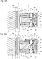
- Fig. 10 , 10a-10c are schematic sectional views of the adjusting device 7 according to FIG Fig. 5 shown in different operating states in the event of an excessively large clearance 10b.
- the schematic enlarged sectional views of the areas IX, IXa, IXb of the adjustment device 7 according to FIG Fig. 10 , 10a-10c are also from Figures 9, 9a-9b shown.
- Fig. 10 , 10a-10c and 9, 9a-9b together form a sequence of images of the mode of operation of the adjustment device 7 when the clearance 10b is too large.
- the pressure medium first flows through the connection bore 34 into the pressure chamber 35 of the first cylinder unit ZE1 and thereby pushes the spindle head 14 of the spindle 15 from the rest position into the end-of-work position, which in Figure 10a and Figure 9a is shown.
- the spindle head 14 moves together with the spindle 15 connected to it in the direction of the adjuster axis 7a towards the brake disk 2.
- the distance covered corresponds to the specified clearance 10 (e.g. 0.5mm for two-sided adjustment or 1.0mm for one-sided adjustment).
- the spindle head 14 is adjusted against the sealing disk 19 by means of the pressure medium in the pressure chamber 35 and presses the return spring 30a against the sealing disk 19.
- the pressure medium passes through one or more overflow channels 36 in the spindle head 14 into the pressure chamber 37 of the second cylinder unit ZE2. Due to the excessive clearance 10b in the starting position in Fig. 10 there is now a clearance 10c with a value greater than zero ( Figure 10a ).
- the adjustment unit spindle 15, piston 16 and adjustment piston 18 together with the brake lining 3 is now pushed onto the brake disc 2. Since the spindle 15 has already reached its final working position due to the path in the first cylinder unit ZE1, an axial movement of the spindle 15 is no longer possible. Therefore, between the spindle 15 and the piston 16, a rotation about the adjuster axis 7a corresponding to the stroke of the adjustment unit (that is, of the piston 16 and the adjustment piston 18) takes place.
- the possibility of rotating the spindle 15 is achieved by the self-locking design of the screw drive (external thread 15b and internal thread 16b) and by the low-friction support of the spindle head 14 with the aid of the roller bearing 30.
- the clearance deviation is compensated for in a single readjustment step.
- the clearance 10a is then reached with the value zero, as in FIG Figure 8b and 9a shown. Is.
- the piston 16 and thus the adjustment unit are also immediately reset due to the backlash-free threaded coupling of the external thread 15b of the spindle 15 and the internal thread 16b of the piston 16 caused by the biasing spring 31.
- the predetermined value of the clearance 10 is set, such as Figure 10c and 9b demonstrate.
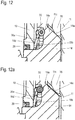
- Fig. 11 , 11a-11c are schematic sectional views of the adjusting device 7 according to FIG Fig. 5 shown in different operating states in the case of an excessively small clearance 10d.
- the schematic enlarged sectional views of the areas XII, XIIa, XIIb, XIIc of the adjustment device 7 according to FIG Fig. 11 , 11a-11c are enlarged in Fig. 12 , 12a-12c shown.
- Fig. 11 , 11a-11c and Fig. 12 , 12a-12c together form a sequence of images of the mode of operation of the adjustment device 7 when the clearance 10d is too small.
- the pressure medium first flows through the connection bore 34 into the pressure chamber 35 of the first cylinder unit ZE1 and thereby pushes the spindle head 14 of the spindle 15 from the rest position into a provisional intermediate position, which is shown in FIG Figure 11a and Figure 12a is shown.
- the complete adjustment unit ie the piston 16 and the adjustment piston 18 with the spindle 15 is also displaced in the direction of the brake disc 2. Since the clearance 10d in the starting position ( Fig. 11 ) is too small, the adjusting mechanism, ie piston 16 and adjusting piston 18, comes to a standstill before the spindle head 14 reaches its end-of-work position, the clearance 10a being reached with the value zero and the pressure section 17 resting on the brake lining 3.
- the pressure medium enters the pressure chamber 37 of the second cylinder unit ZE2 through the overflow channel (s) 36 in the spindle head 14 of the spindle 15, but there is no movement because the adjustment unit, i.e. the piston 16 and the adjustment piston 18, as previously described has already been pressed against the brake disc 2 together with the brake lining 3 by the movement of the spindle 15.
- the piston 16 and thus the adjustment unit are also immediately reset due to the backlash-free threaded coupling of the external thread 15b of the spindle 15 and the internal thread 16b of the piston 16 caused by the biasing spring 31.
- the predetermined value of the clearance 10 is set, such as Figure 11c and 12c demonstrate.
- adjustment device Another requirement of the adjustment device is the possibility of manual adjustability. If, for example, the brake linings 3, 3 'or the friction linings 5, 5' have reached the maximum level of wear, new brake linings 3, 3 'must be installed. For this purpose, the adjustment units (spindle 15, piston 16, adjustment piston 18) of the adjustment devices 7, 7 'of the adjustment device must be manually reset to the initial value.
- the piston 16 has a profiled head on the side facing the brake lining 3, 3 ′, which serves as a force application for a corresponding tool.
- This profiled head is through those already related to above Fig. 6 and Fig. 7 mentioned profiling 17c of the collar 17b of the pressure portion 17 is formed.
- the friction torque generated by the friction spring 25 between the rotatable piston 16 and the non-rotatable adjustment piston 18 must be overcome. Because of this possibility of relative movement between the piston 16 and the adjusting piston 18 resetting is easily possible in the manner described above.
- Fig. 13 a schematic flow diagram of an exemplary embodiment of a method according to the invention for setting a clearance 10 of a disc brake 1 is shown.
- the adjustment devices 7, 7 'of the adjustment device are designed in such a way that the adjustment function is divided into two different process steps.
- a process step 1 is the setting of the clearance 10 and a process step 2 is the adjustment.
- a first and a second method step S1 and S2 contain the process step 1.
- the previously defined clearance 10 is structurally defined in the first cylinder unit ZE1 and is activated after the adjustment device 7 (representing all adjustment devices 7, 7 'of the adjustment device ) starting from the rest position. Upon activation, the adjusting device 7 is acted upon by the pressure medium.
- step S2 it is determined whether the working end position has been reached in the first cylinder unit ZE1.
- the adjustment device 7 is vented in a method step S3.
- the first cylinder unit ZE1 with the spindle head 14 sets the previously determined clearance 10 again in the rest position. This is the case with an unchanged air gap 10.
- step S5 the adjusting device 7 is vented, the first cylinder unit ZE1 with the spindle head 14 in the rest position setting the previously determined clearance 10 again.
- step S6 due to the continued pressurization of the spindle head 14 and its provisional intermediate position without the frictional torque of the rest position, the spindle 15, which is firmly connected to the spindle head 14, is subjected to an axial force in the direction of the adjuster axis 7a, whereby the thread engagement
- the spindle 15 rotates between the spindle 15 and the blocked piston 16 and moves axially towards the brake disk 2. This movement is stopped when the spindle head 14 has reached the working end position.
- step S7 the adjusting device 7 is vented.
- the first cylinder unit ZE1 with the spindle head 14 sets the previously determined clearance 10 again in the rest position.
- the adjustment device only has the adjustment device 7 on the application side.
- the disc brake 1 can have different power drives.
- the application device ZV is operated pneumatically here, for example.
- the adjustment device has only one application-side adjustment device 7 and only one rear-side adjustment device 7 ', which are arranged centrally for each brake lining 3, 3', for example in the case of smaller disc brakes.
- the adjustment device has only one application-side adjustment device 7 and only one rear-side adjustment device 7 ', which are arranged centrally for each brake lining 3, 3', for example in the case of smaller disc brakes.
- more than two adjustment devices 7, 7 'per side are also conceivable.
Landscapes
- Engineering & Computer Science (AREA)
- General Engineering & Computer Science (AREA)
- Mechanical Engineering (AREA)
- Braking Arrangements (AREA)
Claims (29)
- Frein (1) à disque, de préférence à actionnement par l'air comprimé, notamment pour un véhicule automobile, comprenant un disque (2) de frein, un étrier (6) de frein, qui chevauche le disque (2) de frein, et dans lequel est monté un système (ZV) de serrage, dans lequel il est prévu respectivement une garniture (3, 3') de frein de part et d'autre du disque (2) de frein, et comprenant un système de rattrapage ayant au moins un dispositif (7, 7') de rattrapage pour le rattrapage d'une usure de surface de friction sur les garnitures (3, 3') de frein et sur le disque (2) de frein, dans lequel le au moins un dispositif (7, 7') de rattrapage peut fonctionner par un fluide sous pression indépendamment du dispositif (ZV) de serrage,
dans lequel
le au moins un dispositif (7, 7') de rattrapage est constitué en ayant une première unité (ZE1) de cylindre ayant un premier piston de pression, caractérisé
en ce que le au moins un dispositif (7, 7') de rattrapage est constitué en ayant une deuxième, unité (ZE2) de cylindre ayant un deuxième piston de pression, le deuxième piston de pression de la deuxième unité (ZE2) de cylindre ayant un piston (16), qui est en contact avec la garniture (3, 3') de frein, et un piston (18) de rattrapage, qui est monté sur le piston (16). - Frein (1) à disque suivant la revendication 1,
caractérisé en ce que
une course du premier piston de pression de la première unité (ZE1) de cylindre correspond à un jeu (10) des garnitures fixé au préalable du frein (1) à disque. - Frein (1) à disque suivant la revendication 2,
caractérisé en ce que
le au moins un dispositif (7) de rattrapage comprend un boîtier (11 ; 6b) fixe en position et ayant un trou (11b ; 6e) intérieur, une tête (14) de broche, une broche (15), un piston (16), un piston (18) de rattrapage et une rondelle (19) d'étanchéité. - Frein (1) à disque suivant la revendication 3,
caractérisé en ce que
le boîtier (6b) à poste fixe est une partie (6b) arrière de l'étrier (6) de frein, le trou (6e) intérieur étant formé dans la partie (6b) arrière. - Frein (1) à disque suivant la revendication 3 ou 4,
caractérisé en ce que
la première unité (ZE1) de cylindre et la deuxième unité (ZE2) de cylindre sont montées en série dans le boîtier (11 ; 6b) et sont séparées par la rondelle (19) d'étanchéité ou par un fond intermédiaire fixe. - Frein (1) à disque suivant la revendication 5,
caractérisé en ce que
la rondelle (19) d'étanchéité ou le front intermédiaire fixe sépare le trou (11b ; 6e) intérieur en un espace sensiblement fermé entre la rondelle (19) d'étanchéité ou le fond intermédiaire fixe et une paroi (11f ; 6f) de fond du boîtier (11 ; 6b) et en un espace ouvert entre la rondelle (19) d'étanchéité et une ouverture du trou (11b) intérieur, tournée vers le disque (2) de frein, la rondelle (19) d'étanchéité étant rendue étanche au moyen d'un élément (28) d'étanchéité sur son pourtour extérieur par rapport au trou (11b ; 6e) intérieur. - Frein (1) à disque suivant la revendication 6,
caractérisé en ce que
la première unité (ZE1) de cylindre a comme premier piston de pression l'espace fermé et la tête (14) de la broche, la tête (14) de la broche étant reliée à la broche (15) et la broche (15) est dans la deuxième unité (ZE2) de cylindre en prise avec le deuxième piston de pression. - Frein (1) à disque suivant la revendication 7,
caractérisé en ce que
la tête (14) de la broche est pourvue d'un cône (14) extérieur ou d'un autre contour extérieur, tourné vers la paroi (11f ; 6f) de fond du boîtier (11 ; 6b), dans lequel du côté intérieur de la paroi (11f ; 6f) du fond est disposé un cône (11c ; 6d) intérieur ou un contour antagoniste correspondant à l'autre contour extérieur, qui communique avec le cône (14a) extérieur ou avec l'autre contour extérieur de la tête (14) de la broche. - Frein (1) à disque suivant la revendication 8,
caractérisé en ce que
une partie, comprise entre le cône (14a) extérieur ou l'autre contour extérieur de la tête (14) de la broche et le cône (11c ; 6d) intérieur ou le contour antagoniste du boîtier (11 ; 6b) est, au moyen d'un élément (27) d'étanchéité sur le pourtour extérieur de la tête (14) de la broche, rendue étanche par rapport à la paroi intérieure du boîtier (11 ; 6b) et forme un espace (35) de pression de la première unité (ZE1) de cylindre, qui communique avec un raccord (8) pour un fluide sous pression. - Frein (1) à disque suivant la revendication 9,
caractérisé en ce que
la tête (14) de la broche est, en tant que premier piston de pression de la première unité (ZE1) de cylindre, constituée de manière à pouvoir se déplacer longitudinalement en revenant ensemble avec la broche (15) en direction d'un axe (7a, 7'a) de rattrapage, d'une position de repos du dispositif (7, 7') de rattrapage, dans laquelle la tête (14) de la broche est par son cône (14) extérieur ou son autre contour extérieur en contact avec le cône (11c ; 6d) intérieur ou le contour antagoniste du boîtier (11 ; 6b), à une position finale de travail, qui est fixée par la rondelle (19) d'étanchéité, cette course de la tête (14) de la broche correspondant au jeu (10) de garniture fixé au préalable. - Frein (1) à disque suivant la revendication 10,
caractérisé en ce que
la tête (14) de la broche de la première unité (ZE1) de cylindre est ensemble avec la broche (15) constituée de manière à pouvoir tourner autour de l'axe (7a, 7'a) de rattrapage, une possibilité de tourner de la tête (14) de la broche avec la broche (15) dans la position de repos étant bloquée en raison d'un grand couple de frottement entre le cône (14a) extérieur ou l'autre contour extérieur de la tête (14a) de la broche et le cône (11c ; 6d) intérieur ou le contour antagoniste. - Frein (1) à disque suivant la revendication 11,
caractérisé en ce que
en ce que la tête (14a) de la broche est appuyée par un palier (30) axial à roulement, par l'intermédiaire d'un ressort (30a) de rappel, à la rondelle (19) d'étanchéité, le ressort (30a) de rappel appliquant une force axiale en direction de l'axe (7a, 7'a) de rattrapage à la tête (14) de la broche de manière à ce que la tête (14) de la broche soit poussée dans la position de repos, dans laquelle son cône (14a) extérieur ou son autre contour extérieur s'applique fixement au cône (11 ; 6d) intérieur ou au contour antagoniste du boîtier (11 ; 6b). - Frein (1) à disque suivant la revendication 12,
caractérisé en ce que
la tête (14) de la broche a une partie (14c) de guidage, qui s'étend dans un trou (19a) traversant de la rondelle (19) d'étanchéité ou du fond intermédiaire et forme un support et un guidage axial de la tête (14) de la broche sur la rondelle (19) d'étanchéité ou sur le fond intermédiaire, un élément (29) d'étanchéité étant prévu entre la rondelle (19) d'étanchéité ou le fond intermédiaire et la partie (14c) de guidage. - Frein (1) à disque suivant la revendication 13,
caractérisé en ce que
la tête (14) de la broche a au moins un conduit axial comme conduit (36) de trop plein, qui met l'espace (35) sous pression de la première unité (ZE1) de cylindre en communication avec un espace (37) sous pression de la deuxième unité (ZE2) de cylindre. - Frein (1) à disque suivant la revendication 14,
caractérisé en ce que,
la deuxième unité (ZE2) de cylindre comprend l'espace ouvert, le piston (16) et le piston (18) de rattrapage comme deuxième piston de pression, le piston (16) et le piston (18) de rattrapage pouvant coulisser longitudinalement dans l'espace ouvert dans le trou (11b ; 6e) intérieur, le piston (16) pouvant tourner en outre autour de l'axe (7a ; 7'a) de rattrapage. - Frein (1) à disque suivant la revendication 15,
caractérisé en ce que
l'espace (37) sous pression de la deuxième unité (ZE2) de cylindre est fixé dans le trou (11b ; 6e) intérieur entre des parties d'extrémité du piston (16) et du piston (18) de rattrapage et la rondelle (19) d'étanchéité ou le fond intermédiaire. - Frein (1) à disque suivant la revendication 16,
caractérisé en ce que
le piston (16) est monté dans un trou (18f) traversant du piston (18) de rattrapage co-axialement à celui-ci et à l'axe (7a, 7'a) de rattrapage, le piston (18) de rattrapage étant fixé axialement sur le piston (16) et étant rendu étanche par rapport à celui-ci par un élément (26) d'étanchéité, et le piston (16) peut tourner par rapport au piston (18) de rattrapage autour de l'axe (7a , 7'a) de rattrapage, le piston (18) de rattrapage étant rendu étanche par rapport au trou (11b ; 6e) intérieur du boîtier (11 ; 6b) par un élément (26a) d'étanchéité. - Frein (1) à disque suivant la revendication 17,
caractérisé en ce que
il est prévu entre le piston (16) et le piston (18) de rattrapage au moins un ressort (25) de friction, au moyen duquel est produit un couple de frottement pouvant être influencé entre le piston (16) et le piston (18) de réglage. - Frein (1) à disque suivant la revendication 18,
caractérisé en ce que
le piston (18) de rattrapage est empêché de tourner par rapport au boîtier (11 ; 6b) à poste fixe par au moins un ou plusieurs éléments (20) de guidage constitués sous la forme de clavettes de guidage. - Frein (1) à disque suivant la revendication 19,
caractérisé en ce que
la broche (15) est constituée sous la forme d'une broche filetée ayant un filetage (15b) extérieur, s'étend dans le trou (11b ; 6e) intérieur du boîtier (11 ; 6b) et est en prise avec le piston (16) par son filetage (15b) extérieur avec un taraudage (16b) du piston (16). - Frein (1) à disque suivant la revendication 20,
caractérisé en ce que
le filetage (15b) extérieur de la broche (15) et le taraudage (16b) du piston (16) sont réalisés sous la forme de filet non autobloquant. - Frein (1) à disque suivant la revendication 20 ou 21,
caractérisé en ce que
il est prévu un ressort (31) de précontrainte entre la broche (15) et le piston (16), au moyen duquel le filetage (15b) extérieur de la broche (15) est précontraint axialement par rapport au taraudage (16b) du piston. - Frein (1) à disque suivant l'une des revendication 20 à 22,
caractérisé en ce que
le taraudage (16b) du piston (16) s'étend d'une partie (16a) d'extrémité du piston (16), tournée vers la rondelle (19) d'étanchéité, en direction du disque (2) de frein et débouche dans un trou (16d) axial, le trou axial étant fermé d'une manière étanche à la pression par un capuchon (22) d'étanchéité ou par un autre procédé d'étanchéité. - Frein (1) à disque suivant la revendication 23,
caractérisé en ce que
l'espace (37) sous pression de la deuxième unité (ZE2) de cylindre est rendu étanche vis-à-vis de l'atmosphère par l'élément (26) d'étanchéité entre le piston (16) et le piston (18) de rattrapage, par l'élément (26a) d'étanchéité entre le piston (18) de rattrapage et le trou (11b ; 6e) intérieur du boîtier (11 ; 6b) et par le capuchon (22) d'étanchéité dans le trou (16d) axial du piston (16). - Frein (1) à disque suivant l'une des revendications précédentes,
caractérisé en ce que
le piston (16) est, par une partie (17, 17') d'application d'une pression, en contact avec la garniture (3, 3') de frein, la partie (17, 17') d'application d'une pression ayant un collet (17b) faisant le tour et ayant un profilage (17c) comme application d'une force pour un rappel manuel par rotation du piston (16). - Procédé de réglage d'un jeu (10) de garniture d'un frein (1) à disque suivant l'une des revendications précédentes, de préférence à actionnement par l'air comprimé, notamment pour un véhicule automobile, comprenant un disque (2), de frein, un étrier (6) de frein, qui chevauche le disque (2) de frein, et dans lequel est monté un système (ZV) de serrage, dans lequel il est prévu respectivement une garniture (3, 3') de frein de part et d'autre du disque (2) de frein, et comprenant un système de rattrapage ayant au moins un dispositif (7, 7') de rattrapage pour le rattrapage d'une usure de surface de friction sur les garnitures (3, 3') de frein et sur le disque (2) de frein, dans lequel le au moins un dispositif (7, 7') de rattrapage peut fonctionner par un fluide sous pression indépendamment du dispositif (ZV) de serrage,
caractérisé par
les stades de procédéS1 Activation du disposition (7, 7') de rattrapage par alimentation en un fluide sous pression et déplacement d'une tête (14) de broche de la première unité (ZE1) de cylindre à partir d'une position de repos ;S2 Constatation du point de savoir si la tête (14) de la broche a atteint une position finale de travail dans la première unité (ZE1) de cylindre ;S3 Réglage à nouveau du jeu (10) de garniture fixé par construction au préalable dans la première unité (ZE1) de cylindre, par la première unité (ZE1) de cylindre, par mise à l'atmosphère du dispositif (7, 7') de rattrapage, si la position finale de travail est atteinte et si la garniture (3, 3') de frein s'applique déjà au disque (2) de frein et si un jeu (10a) de garniture en cours est devenu nul; ouS4 Déplacement par la deuxième unité (ZE2) de cylindre, d'un piston (16) et d'un piston (18) de travail qui y est relié, si la position finale de travail est atteinte et si la garniture (3, 3') de frein, en raison d'un jeu (10b) de garniture trop grand, ne s'applique pas encore au disque de frein ; etS5 Réglage à nouveau, par la première unité (ZE1) de cylindre, par mise à l'atmosphère du dispositif (7, 7') de rattrapage, du jeu (10) de garniture fixé par construction au préalable dans la première unité (ZE1) de cylindre, si la garniture (3, 3') de frein s'applique au disque (2) de frein et si un jeu (10a) de garniture en cours est devenu nul ;ouS6 Réglage à nouveau de la tête (14) de la broche à partir d'une position intermédiaire par la première unité (ZE1) de cylindre, si la tête (14) de la broche n'a pas encore atteint la position finale de travail et si la garniture (3, 3') de frein, en raison d'un jeu (10d) de garniture trop petit, s'applique au disque (2) de frein et si un jeu (10a) de garniture en cours est devenu nul; etS7 Réglage à nouveau par la première unité (ZE1) de cylindre, par mise à l'atmosphère du dispositif (7, 7') de rattrapage, du jeu (10) de garniture fixé par construction au préalable dans la première (ZE1) de cylindre, si la tête (14) de la broche a atteint la position finale de travail. - Procédé suivant la revendication 26,
caractérisé en ce que,
dans le stade S4 du procédé, un rapetissement du jeu (10b) de garniture trop grand a lieu par le fait qu'une broche (15) bloquée axialement dans la position finale de travail par la tête (14) de broche qui lui est reliée, tourne autour d'un axe (7a, 7'a) de rattrapage par le déplacement du piston (16) et du piston (18) de rattrapage provoqué par une prise sans autoblocage entre la broche et le piston, jusqu'à ce que le piston (16) et le piston (18) de rattrapage aient mis la garniture (3, 3') de frein en application sur le disque (2) de frein. - Procédé suivant la revendication 26 ou 27,
caractérisé en ce que,
dans le stade S6 du procédé, un agrandissement du jeu (10d) de garniture trop petit a lieu par le fait qu'une broche (15) déplaçable axialement dans la position intermédiaire est déplacée par le déplacement de la tête (14) de la broche qui lui est reliée et tourne par une prise sans autoblocage de la broche (15) et du piston (16) bloqué, jusqu'à ce que la tête (14) de la broche ait atteint la position finale de travail. - Procédé suivant l'une des revendications 26 à 28, caractérisé en ce que,
dans les stades S3, S5 et S7 du procédé, la tête (14) de la broche est, après la mise à l'atmosphère, rappelée de la position finale de travail à la position de repos au moyen d'un ressort (30a) de rappel, le jeu (10) de garniture fixé au préalable par construction dans la première unité (ZE1) de cylindre étant réglé à nouveau.
Applications Claiming Priority (2)
| Application Number | Priority Date | Filing Date | Title |
|---|---|---|---|
| DE102017104443.4A DE102017104443A1 (de) | 2017-03-03 | 2017-03-03 | Scheibenbremse mit einer Nachstellvorrichtung |
| PCT/EP2018/055081 WO2018158386A1 (fr) | 2017-03-03 | 2018-03-01 | Frein à disque avec un dispositif de réglage et procédé pour le réglage d'une distance de dégagement d'un tel frein à disque |
Publications (2)
| Publication Number | Publication Date |
|---|---|
| EP3589859A1 EP3589859A1 (fr) | 2020-01-08 |
| EP3589859B1 true EP3589859B1 (fr) | 2021-05-12 |
Family
ID=61599122
Family Applications (1)
| Application Number | Title | Priority Date | Filing Date |
|---|---|---|---|
| EP18709514.6A Active EP3589859B1 (fr) | 2017-03-03 | 2018-03-01 | Frein à disque avec un dispositif de réglage et procédé pour le réglage d'une distance de dégagement d'un tel frein à disque |
Country Status (4)
| Country | Link |
|---|---|
| EP (1) | EP3589859B1 (fr) |
| CN (1) | CN110546397B (fr) |
| DE (1) | DE102017104443A1 (fr) |
| WO (1) | WO2018158386A1 (fr) |
Families Citing this family (1)
| Publication number | Priority date | Publication date | Assignee | Title |
|---|---|---|---|---|
| US12158188B2 (en) * | 2019-08-16 | 2024-12-03 | Zf Cv Systems Europe Bv | Disc brake having an adjusting spindle |
Family Cites Families (11)
| Publication number | Priority date | Publication date | Assignee | Title |
|---|---|---|---|---|
| FR2559563B1 (fr) * | 1984-02-13 | 1989-11-24 | Kelsey Hayes Co | Dispositif de reglage pour frein a disque |
| DE4017065A1 (de) * | 1990-05-26 | 1991-11-28 | Teves Gmbh Alfred | Nachstellvorrichtung fuer eine bremse mit rueckstellvorrichtung |
| DE19521634A1 (de) * | 1995-06-14 | 1996-12-19 | Teves Gmbh Alfred | Scheibenbremse mit automatischer Nachstellvorrichtung |
| DE19729024C1 (de) | 1997-07-08 | 1999-01-28 | Knorr Bremse Systeme | Verschleißnachstellvorrichtung für Scheibenbremsen |
| DE50302971D1 (de) | 2002-09-23 | 2006-05-24 | Knorr Bremse Systeme | Pneumatisch betätigte scheibenbremse mit nachstelleinrichtung |
| JP4079916B2 (ja) * | 2003-08-13 | 2008-04-23 | 曙ブレーキ工業株式会社 | オーバアジャスト防止付き自動間隙調整機構を備えたブレーキ装置 |
| DE102012003506A1 (de) | 2012-02-22 | 2013-08-22 | Knorr-Bremse Systeme für Nutzfahrzeuge GmbH | Scheibenbremse mit einer Belagverschleissnachstellvorrichtung und Verfahren zum Einstellen eines Lüftspiels |
| DE102012108672B3 (de) | 2012-09-17 | 2014-02-06 | Knorr-Bremse Systeme für Nutzfahrzeuge GmbH | Nachstelleinrichtung einer Scheibenbremse, eine entsprechende Scheibenbremse und Verfahren zum Betreiben einer Verschleißnachstellvorrichtung einer Scheibenbremse |
| CN203362922U (zh) * | 2013-07-24 | 2013-12-25 | 中国重汽集团济南动力有限公司 | 一种盘式制动器间隙自动调整装置 |
| CN103711820B (zh) * | 2013-09-13 | 2016-09-14 | 重庆昌德成电子有限公司 | 一种自动补偿机械盘式制动器 |
| KR101853779B1 (ko) * | 2014-04-28 | 2018-05-02 | 주식회사 만도 | 디스크 브레이크 |
-
2017
- 2017-03-03 DE DE102017104443.4A patent/DE102017104443A1/de not_active Ceased
-
2018
- 2018-03-01 EP EP18709514.6A patent/EP3589859B1/fr active Active
- 2018-03-01 CN CN201880027404.6A patent/CN110546397B/zh not_active Expired - Fee Related
- 2018-03-01 WO PCT/EP2018/055081 patent/WO2018158386A1/fr not_active Ceased
Non-Patent Citations (1)
| Title |
|---|
| None * |
Also Published As
| Publication number | Publication date |
|---|---|
| CN110546397A (zh) | 2019-12-06 |
| CN110546397B (zh) | 2021-05-07 |
| EP3589859A1 (fr) | 2020-01-08 |
| WO2018158386A1 (fr) | 2018-09-07 |
| DE102017104443A1 (de) | 2018-09-06 |
Similar Documents
| Publication | Publication Date | Title |
|---|---|---|
| EP3173651B1 (fr) | Dispositif de réglage d'un frein à disque et frein à disque correspondant | |
| EP3149353B1 (fr) | Frein à disque, étrier de frein et jeu de plaquettes de frein pour un frein à disque | |
| DE2526525A1 (de) | Bremsanlage | |
| DE102012108676B3 (de) | Scheibenbremse mit einer Verschleißnachstellvorrichtung | |
| EP2895762A1 (fr) | Frein à disque avec système de synchronisation | |
| EP2989344B1 (fr) | Frein à disque pourvu d'un dispositif bidirectionnel de rattrapage d'usure, et dispositif bidirectionnel de rattrapage d'usure | |
| DE2438460C2 (de) | Mechanisch betätigte Scheibenbremse | |
| DE102012006082A1 (de) | Scheibenbremse mit Rückstelleinrichtung und entsprechender Bremsbelag | |
| EP3487735B1 (fr) | Frein de service d'un véhicule avec assistance electroméchanique et hydraulique | |
| EP1794045B1 (fr) | Cylindre de frein pour freins de vehicules | |
| DE102015114440B4 (de) | Scheibenbremse mit Synchronisationseinheit | |
| EP3589859B1 (fr) | Frein à disque avec un dispositif de réglage et procédé pour le réglage d'une distance de dégagement d'un tel frein à disque | |
| DE102006033333A1 (de) | Hydraulische Fahrzeugbremse mit integrierter elektromechanisch betätigbarer Feststellbremse | |
| EP2002141B1 (fr) | Frein à disque à auto-amplification et procédé de commande de celui-ci | |
| EP3653480A1 (fr) | Étrier de frein d'un deux-roues | |
| EP0636220B1 (fr) | Frein a disque a air comprime | |
| EP2002140A1 (fr) | Frein à disque à auto-amplification et procédé de commande de celui-ci | |
| DE102015101996A1 (de) | Radbremseinheit, insbesondere Scheibenbremse | |
| DE102008006481B4 (de) | Scheibenbremse für ein Nutzfahrzeug | |
| DE102015108304A1 (de) | Scheibenbremse, und Bremsbelagsatz für eine Scheibenbremse | |
| EP1013959B1 (fr) | Cylindre de frein hydraulique pour actionner les machoires d'un frein à tambour | |
| DE1813560C3 (de) | Selbsttätige Nachstellvorrichtung für Scheibenbremsen | |
| DE2408216C2 (de) | Selbsttätige Nachstellvorrichtung | |
| DE9218245U1 (de) | Druckluftbetätigte Scheibenbremse | |
| DE1813560B2 (de) | Selbsttaetige nachstellvorrichtung fuer scheibenbremsen |
Legal Events
| Date | Code | Title | Description |
|---|---|---|---|
| STAA | Information on the status of an ep patent application or granted ep patent |
Free format text: STATUS: UNKNOWN |
|
| STAA | Information on the status of an ep patent application or granted ep patent |
Free format text: STATUS: THE INTERNATIONAL PUBLICATION HAS BEEN MADE |
|
| PUAI | Public reference made under article 153(3) epc to a published international application that has entered the european phase |
Free format text: ORIGINAL CODE: 0009012 |
|
| STAA | Information on the status of an ep patent application or granted ep patent |
Free format text: STATUS: REQUEST FOR EXAMINATION WAS MADE |
|
| 17P | Request for examination filed |
Effective date: 20191004 |
|
| AK | Designated contracting states |
Kind code of ref document: A1 Designated state(s): AL AT BE BG CH CY CZ DE DK EE ES FI FR GB GR HR HU IE IS IT LI LT LU LV MC MK MT NL NO PL PT RO RS SE SI SK SM TR |
|
| AX | Request for extension of the european patent |
Extension state: BA ME |
|
| DAV | Request for validation of the european patent (deleted) | ||
| DAX | Request for extension of the european patent (deleted) | ||
| GRAP | Despatch of communication of intention to grant a patent |
Free format text: ORIGINAL CODE: EPIDOSNIGR1 |
|
| STAA | Information on the status of an ep patent application or granted ep patent |
Free format text: STATUS: GRANT OF PATENT IS INTENDED |
|
| INTG | Intention to grant announced |
Effective date: 20201008 |
|
| GRAS | Grant fee paid |
Free format text: ORIGINAL CODE: EPIDOSNIGR3 |
|
| GRAA | (expected) grant |
Free format text: ORIGINAL CODE: 0009210 |
|
| STAA | Information on the status of an ep patent application or granted ep patent |
Free format text: STATUS: THE PATENT HAS BEEN GRANTED |
|
| AK | Designated contracting states |
Kind code of ref document: B1 Designated state(s): AL AT BE BG CH CY CZ DE DK EE ES FI FR GB GR HR HU IE IS IT LI LT LU LV MC MK MT NL NO PL PT RO RS SE SI SK SM TR |
|
| REG | Reference to a national code |
Ref country code: GB Ref legal event code: FG4D Free format text: NOT ENGLISH |
|
| REG | Reference to a national code |
Ref country code: CH Ref legal event code: EP |
|
| REG | Reference to a national code |
Ref country code: DE Ref legal event code: R096 Ref document number: 502018005233 Country of ref document: DE |
|
| REG | Reference to a national code |
Ref country code: IE Ref legal event code: FG4D Free format text: LANGUAGE OF EP DOCUMENT: GERMAN |
|
| REG | Reference to a national code |
Ref country code: AT Ref legal event code: REF Ref document number: 1392387 Country of ref document: AT Kind code of ref document: T Effective date: 20210615 |
|
| REG | Reference to a national code |
Ref country code: SE Ref legal event code: TRGR |
|
| REG | Reference to a national code |
Ref country code: LT Ref legal event code: MG9D |
|
| REG | Reference to a national code |
Ref country code: NL Ref legal event code: MP Effective date: 20210512 |
|
| PG25 | Lapsed in a contracting state [announced via postgrant information from national office to epo] |
Ref country code: FI Free format text: LAPSE BECAUSE OF FAILURE TO SUBMIT A TRANSLATION OF THE DESCRIPTION OR TO PAY THE FEE WITHIN THE PRESCRIBED TIME-LIMIT Effective date: 20210512 Ref country code: LT Free format text: LAPSE BECAUSE OF FAILURE TO SUBMIT A TRANSLATION OF THE DESCRIPTION OR TO PAY THE FEE WITHIN THE PRESCRIBED TIME-LIMIT Effective date: 20210512 Ref country code: HR Free format text: LAPSE BECAUSE OF FAILURE TO SUBMIT A TRANSLATION OF THE DESCRIPTION OR TO PAY THE FEE WITHIN THE PRESCRIBED TIME-LIMIT Effective date: 20210512 Ref country code: BG Free format text: LAPSE BECAUSE OF FAILURE TO SUBMIT A TRANSLATION OF THE DESCRIPTION OR TO PAY THE FEE WITHIN THE PRESCRIBED TIME-LIMIT Effective date: 20210812 |
|
| PG25 | Lapsed in a contracting state [announced via postgrant information from national office to epo] |
Ref country code: IS Free format text: LAPSE BECAUSE OF FAILURE TO SUBMIT A TRANSLATION OF THE DESCRIPTION OR TO PAY THE FEE WITHIN THE PRESCRIBED TIME-LIMIT Effective date: 20210912 Ref country code: GR Free format text: LAPSE BECAUSE OF FAILURE TO SUBMIT A TRANSLATION OF THE DESCRIPTION OR TO PAY THE FEE WITHIN THE PRESCRIBED TIME-LIMIT Effective date: 20210813 Ref country code: PL Free format text: LAPSE BECAUSE OF FAILURE TO SUBMIT A TRANSLATION OF THE DESCRIPTION OR TO PAY THE FEE WITHIN THE PRESCRIBED TIME-LIMIT Effective date: 20210512 Ref country code: PT Free format text: LAPSE BECAUSE OF FAILURE TO SUBMIT A TRANSLATION OF THE DESCRIPTION OR TO PAY THE FEE WITHIN THE PRESCRIBED TIME-LIMIT Effective date: 20210913 Ref country code: NO Free format text: LAPSE BECAUSE OF FAILURE TO SUBMIT A TRANSLATION OF THE DESCRIPTION OR TO PAY THE FEE WITHIN THE PRESCRIBED TIME-LIMIT Effective date: 20210812 Ref country code: LV Free format text: LAPSE BECAUSE OF FAILURE TO SUBMIT A TRANSLATION OF THE DESCRIPTION OR TO PAY THE FEE WITHIN THE PRESCRIBED TIME-LIMIT Effective date: 20210512 Ref country code: RS Free format text: LAPSE BECAUSE OF FAILURE TO SUBMIT A TRANSLATION OF THE DESCRIPTION OR TO PAY THE FEE WITHIN THE PRESCRIBED TIME-LIMIT Effective date: 20210512 |
|
| PG25 | Lapsed in a contracting state [announced via postgrant information from national office to epo] |
Ref country code: NL Free format text: LAPSE BECAUSE OF FAILURE TO SUBMIT A TRANSLATION OF THE DESCRIPTION OR TO PAY THE FEE WITHIN THE PRESCRIBED TIME-LIMIT Effective date: 20210512 |
|
| PG25 | Lapsed in a contracting state [announced via postgrant information from national office to epo] |
Ref country code: ES Free format text: LAPSE BECAUSE OF FAILURE TO SUBMIT A TRANSLATION OF THE DESCRIPTION OR TO PAY THE FEE WITHIN THE PRESCRIBED TIME-LIMIT Effective date: 20210512 Ref country code: EE Free format text: LAPSE BECAUSE OF FAILURE TO SUBMIT A TRANSLATION OF THE DESCRIPTION OR TO PAY THE FEE WITHIN THE PRESCRIBED TIME-LIMIT Effective date: 20210512 Ref country code: SK Free format text: LAPSE BECAUSE OF FAILURE TO SUBMIT A TRANSLATION OF THE DESCRIPTION OR TO PAY THE FEE WITHIN THE PRESCRIBED TIME-LIMIT Effective date: 20210512 Ref country code: SM Free format text: LAPSE BECAUSE OF FAILURE TO SUBMIT A TRANSLATION OF THE DESCRIPTION OR TO PAY THE FEE WITHIN THE PRESCRIBED TIME-LIMIT Effective date: 20210512 Ref country code: CZ Free format text: LAPSE BECAUSE OF FAILURE TO SUBMIT A TRANSLATION OF THE DESCRIPTION OR TO PAY THE FEE WITHIN THE PRESCRIBED TIME-LIMIT Effective date: 20210512 Ref country code: DK Free format text: LAPSE BECAUSE OF FAILURE TO SUBMIT A TRANSLATION OF THE DESCRIPTION OR TO PAY THE FEE WITHIN THE PRESCRIBED TIME-LIMIT Effective date: 20210512 Ref country code: RO Free format text: LAPSE BECAUSE OF FAILURE TO SUBMIT A TRANSLATION OF THE DESCRIPTION OR TO PAY THE FEE WITHIN THE PRESCRIBED TIME-LIMIT Effective date: 20210512 |
|
| REG | Reference to a national code |
Ref country code: DE Ref legal event code: R097 Ref document number: 502018005233 Country of ref document: DE |
|
| PLBE | No opposition filed within time limit |
Free format text: ORIGINAL CODE: 0009261 |
|
| STAA | Information on the status of an ep patent application or granted ep patent |
Free format text: STATUS: NO OPPOSITION FILED WITHIN TIME LIMIT |
|
| 26N | No opposition filed |
Effective date: 20220215 |
|
| PGFP | Annual fee paid to national office [announced via postgrant information from national office to epo] |
Ref country code: GB Payment date: 20220324 Year of fee payment: 5 |
|
| PG25 | Lapsed in a contracting state [announced via postgrant information from national office to epo] |
Ref country code: IS Free format text: LAPSE BECAUSE OF FAILURE TO SUBMIT A TRANSLATION OF THE DESCRIPTION OR TO PAY THE FEE WITHIN THE PRESCRIBED TIME-LIMIT Effective date: 20210912 Ref country code: AL Free format text: LAPSE BECAUSE OF FAILURE TO SUBMIT A TRANSLATION OF THE DESCRIPTION OR TO PAY THE FEE WITHIN THE PRESCRIBED TIME-LIMIT Effective date: 20210512 |
|
| PGFP | Annual fee paid to national office [announced via postgrant information from national office to epo] |
Ref country code: SE Payment date: 20220324 Year of fee payment: 5 |
|
| PGFP | Annual fee paid to national office [announced via postgrant information from national office to epo] |
Ref country code: IT Payment date: 20220331 Year of fee payment: 5 |
|
| PG25 | Lapsed in a contracting state [announced via postgrant information from national office to epo] |
Ref country code: MC Free format text: LAPSE BECAUSE OF FAILURE TO SUBMIT A TRANSLATION OF THE DESCRIPTION OR TO PAY THE FEE WITHIN THE PRESCRIBED TIME-LIMIT Effective date: 20210512 |
|
| REG | Reference to a national code |
Ref country code: CH Ref legal event code: PL |
|
| REG | Reference to a national code |
Ref country code: BE Ref legal event code: MM Effective date: 20220331 |
|
| PG25 | Lapsed in a contracting state [announced via postgrant information from national office to epo] |
Ref country code: LU Free format text: LAPSE BECAUSE OF NON-PAYMENT OF DUE FEES Effective date: 20220301 Ref country code: LI Free format text: LAPSE BECAUSE OF NON-PAYMENT OF DUE FEES Effective date: 20220331 Ref country code: IE Free format text: LAPSE BECAUSE OF NON-PAYMENT OF DUE FEES Effective date: 20220301 Ref country code: FR Free format text: LAPSE BECAUSE OF NON-PAYMENT OF DUE FEES Effective date: 20220331 Ref country code: CH Free format text: LAPSE BECAUSE OF NON-PAYMENT OF DUE FEES Effective date: 20220331 |
|
| PG25 | Lapsed in a contracting state [announced via postgrant information from national office to epo] |
Ref country code: BE Free format text: LAPSE BECAUSE OF NON-PAYMENT OF DUE FEES Effective date: 20220331 |
|
| P01 | Opt-out of the competence of the unified patent court (upc) registered |
Effective date: 20230607 |
|
| REG | Reference to a national code |
Ref country code: SE Ref legal event code: EUG |
|
| GBPC | Gb: european patent ceased through non-payment of renewal fee |
Effective date: 20230301 |
|
| PG25 | Lapsed in a contracting state [announced via postgrant information from national office to epo] |
Ref country code: GB Free format text: LAPSE BECAUSE OF NON-PAYMENT OF DUE FEES Effective date: 20230301 |
|
| PG25 | Lapsed in a contracting state [announced via postgrant information from national office to epo] |
Ref country code: SE Free format text: LAPSE BECAUSE OF NON-PAYMENT OF DUE FEES Effective date: 20230302 Ref country code: GB Free format text: LAPSE BECAUSE OF NON-PAYMENT OF DUE FEES Effective date: 20230301 |
|
| PG25 | Lapsed in a contracting state [announced via postgrant information from national office to epo] |
Ref country code: MK Free format text: LAPSE BECAUSE OF FAILURE TO SUBMIT A TRANSLATION OF THE DESCRIPTION OR TO PAY THE FEE WITHIN THE PRESCRIBED TIME-LIMIT Effective date: 20210512 Ref country code: CY Free format text: LAPSE BECAUSE OF FAILURE TO SUBMIT A TRANSLATION OF THE DESCRIPTION OR TO PAY THE FEE WITHIN THE PRESCRIBED TIME-LIMIT Effective date: 20210512 Ref country code: IT Free format text: LAPSE BECAUSE OF NON-PAYMENT OF DUE FEES Effective date: 20230301 |
|
| PGFP | Annual fee paid to national office [announced via postgrant information from national office to epo] |
Ref country code: DE Payment date: 20240328 Year of fee payment: 7 |
|
| REG | Reference to a national code |
Ref country code: AT Ref legal event code: MM01 Ref document number: 1392387 Country of ref document: AT Kind code of ref document: T Effective date: 20230301 |
|
| PG25 | Lapsed in a contracting state [announced via postgrant information from national office to epo] |
Ref country code: HU Free format text: LAPSE BECAUSE OF FAILURE TO SUBMIT A TRANSLATION OF THE DESCRIPTION OR TO PAY THE FEE WITHIN THE PRESCRIBED TIME-LIMIT; INVALID AB INITIO Effective date: 20180301 |
|
| PG25 | Lapsed in a contracting state [announced via postgrant information from national office to epo] |
Ref country code: AT Free format text: LAPSE BECAUSE OF NON-PAYMENT OF DUE FEES Effective date: 20230301 |
|
| PG25 | Lapsed in a contracting state [announced via postgrant information from national office to epo] |
Ref country code: AT Free format text: LAPSE BECAUSE OF NON-PAYMENT OF DUE FEES Effective date: 20230301 |
|
| PG25 | Lapsed in a contracting state [announced via postgrant information from national office to epo] |
Ref country code: MT Free format text: LAPSE BECAUSE OF FAILURE TO SUBMIT A TRANSLATION OF THE DESCRIPTION OR TO PAY THE FEE WITHIN THE PRESCRIBED TIME-LIMIT Effective date: 20210512 |
|
| REG | Reference to a national code |
Ref country code: DE Ref legal event code: R119 Ref document number: 502018005233 Country of ref document: DE |
|
| PG25 | Lapsed in a contracting state [announced via postgrant information from national office to epo] |
Ref country code: TR Free format text: LAPSE BECAUSE OF FAILURE TO SUBMIT A TRANSLATION OF THE DESCRIPTION OR TO PAY THE FEE WITHIN THE PRESCRIBED TIME-LIMIT Effective date: 20210512 |
|
| PG25 | Lapsed in a contracting state [announced via postgrant information from national office to epo] |
Ref country code: DE Free format text: LAPSE BECAUSE OF NON-PAYMENT OF DUE FEES Effective date: 20251001 |
|
| PGFP | Annual fee paid to national office [announced via postgrant information from national office to epo] |
Ref country code: AT Payment date: 20260410 Year of fee payment: 5 |