EP3590120B1 - Disjoncteur à haute tension avec robustnesse améliorée - Google Patents
Disjoncteur à haute tension avec robustnesse améliorée Download PDFInfo
- Publication number
- EP3590120B1 EP3590120B1 EP18707720.1A EP18707720A EP3590120B1 EP 3590120 B1 EP3590120 B1 EP 3590120B1 EP 18707720 A EP18707720 A EP 18707720A EP 3590120 B1 EP3590120 B1 EP 3590120B1
- Authority
- EP
- European Patent Office
- Prior art keywords
- interrupter unit
- respect
- central axis
- steps
- nozzle
- Prior art date
- Legal status (The legal status is an assumption and is not a legal conclusion. Google has not performed a legal analysis and makes no representation as to the accuracy of the status listed.)
- Active
Links
Images


Classifications
-
- H—ELECTRICITY
- H01—ELECTRIC ELEMENTS
- H01H—ELECTRIC SWITCHES; RELAYS; SELECTORS; EMERGENCY PROTECTIVE DEVICES
- H01H33/00—High-tension or heavy-current switches with arc-extinguishing or arc-preventing means
- H01H33/70—Switches with separate means for directing, obtaining, or increasing flow of arc-extinguishing fluid
- H01H33/7015—Switches with separate means for directing, obtaining, or increasing flow of arc-extinguishing fluid characterised by flow directing elements associated with contacts
- H01H33/7023—Switches with separate means for directing, obtaining, or increasing flow of arc-extinguishing fluid characterised by flow directing elements associated with contacts characterised by an insulating tubular gas flow enhancing nozzle
- H01H33/703—Switches with separate means for directing, obtaining, or increasing flow of arc-extinguishing fluid characterised by flow directing elements associated with contacts characterised by an insulating tubular gas flow enhancing nozzle having special gas flow directing elements, e.g. grooves, extensions
-
- H—ELECTRICITY
- H01—ELECTRIC ELEMENTS
- H01H—ELECTRIC SWITCHES; RELAYS; SELECTORS; EMERGENCY PROTECTIVE DEVICES
- H01H1/00—Contacts
- H01H1/12—Contacts characterised by the manner in which co-operating contacts engage
- H01H1/36—Contacts characterised by the manner in which co-operating contacts engage by sliding
- H01H1/38—Plug-and-socket contacts
- H01H1/385—Contact arrangements for high voltage gas blast circuit breakers
-
- H—ELECTRICITY
- H01—ELECTRIC ELEMENTS
- H01H—ELECTRIC SWITCHES; RELAYS; SELECTORS; EMERGENCY PROTECTIVE DEVICES
- H01H33/00—High-tension or heavy-current switches with arc-extinguishing or arc-preventing means
- H01H33/70—Switches with separate means for directing, obtaining, or increasing flow of arc-extinguishing fluid
- H01H33/7015—Switches with separate means for directing, obtaining, or increasing flow of arc-extinguishing fluid characterised by flow directing elements associated with contacts
- H01H33/7023—Switches with separate means for directing, obtaining, or increasing flow of arc-extinguishing fluid characterised by flow directing elements associated with contacts characterised by an insulating tubular gas flow enhancing nozzle
-
- H—ELECTRICITY
- H01—ELECTRIC ELEMENTS
- H01H—ELECTRIC SWITCHES; RELAYS; SELECTORS; EMERGENCY PROTECTIVE DEVICES
- H01H33/00—High-tension or heavy-current switches with arc-extinguishing or arc-preventing means
- H01H33/70—Switches with separate means for directing, obtaining, or increasing flow of arc-extinguishing fluid
- H01H33/88—Switches with separate means for directing, obtaining, or increasing flow of arc-extinguishing fluid the flow of arc-extinguishing fluid being produced or increased by movement of pistons or other pressure-producing parts
- H01H33/90—Switches with separate means for directing, obtaining, or increasing flow of arc-extinguishing fluid the flow of arc-extinguishing fluid being produced or increased by movement of pistons or other pressure-producing parts this movement being effected by or in conjunction with the contact-operating mechanism
- H01H33/91—Switches with separate means for directing, obtaining, or increasing flow of arc-extinguishing fluid the flow of arc-extinguishing fluid being produced or increased by movement of pistons or other pressure-producing parts this movement being effected by or in conjunction with the contact-operating mechanism the arc-extinguishing fluid being air or gas
Definitions
- the subject matter described herein relates generally to a gas-insulated high-voltage circuit breaker, and more particularly, to a circuit breaker having an improved robustness against propagation of an electrical breakdown.
- the nozzle typically also serves for guiding a gas stream for extinguishing, or blowing off, the arc.
- the gas is typically guided by a dedicated passage in the nozzle, the heating channel, which ends close to the arcing zone.
- the gas is guided directly onto the developing arc.
- circuit breakers A potential problem in circuit breakers are electrical breakdowns during an interruption operation, which sometimes enter the heating channel. This is an undesirable behaviour.
- EP 1 218 906 B1 discloses a high-voltage power switch, wherein the distance between the first arc contact piece and a second zone of the gas flow-off channel is greater than the doubled diameter of the channel over its first zone.
- US 2015/021297 A1 discloses a circuit breaker with quenching gas, wherein a ratio of the pressurization chamber outflow limiting area to the nozzle outflow limiting area is less than 1.1:1.
- DE 199 36 987 C1 discloses a high-voltage switch, wherein a radius of curvature of an electrode is specifically less than the radius of curvature of the arc-contact tip lying opposite to it.
- An interrupter unit for a gas blast circuit breaker having a central axis A, is provided.
- the interrupter unit comprises a first contact portion having an arcing contact; a second contact portion comprising a cylinder shaft and a pin contact; a nozzle, comprising an insulating material and fixed to the first contact portion, the nozzle having a first section surrounding the arcing contact, an intermediate cylindrical section and a divergent section and wherein a heating channel is provided having a circumferential opening leading into the nozzle, so as to guide a compressed gas into a zone between the arcing contact and the pin contact during an opening operation of the interrupter unit.
- circumferential edge region between a first side wall of the heating channel, being oriented towards the second contact portion, and a wall of the cylindrical section of the nozzle, and wherein the circumferential edge region comprises at least one edge with an enveloping radius (which may also be called an effective radius) of at most 2 mm.
- an electrical contact through which the nominal current passes through the interrupter unit in a circuit breaker is called a main contact or nominal contact
- breaker contact the combination of a main contact and an arcing contact
- the circuit breaker comprises two breaker contacts or moving contacts, each comprising a main contact and an arcing contact.
- one of the arcing contacts is configured as a hollow type, also called tulip, and the other arcing contact is configured as a pin contact.
- a gas-insulated high-voltage circuit breaker for interrupting a current between a first breaker contact and a second breaker contact.
- the breaker contacts are typically adapted for electrically interconnecting the circuit breaker to the electrical circuit to be protected.
- a high voltage is a voltage of at least about 70 kV or higher.
- a high-voltage circuit breaker is a circuit breaker rated to a nominal voltage of at least about 70 kV or higher.
- the arc-extinguishing medium comprises a gas.
- the circuit breaker includes an encapsulating case which defines a volume for the gas.
- the circuit breaker typically includes a gas blast system configured to extinguish an arc formed between a first arcing contact and a second or mating arcing contact of the circuit breaker during a stage of the current interruption operation.
- a gas blast system configured to extinguish an arc formed between a first arcing contact and a second or mating arcing contact of the circuit breaker during a stage of the current interruption operation.
- an arc develops in an arcing zone between the two arcing contacts, basically and substantially along and parallel to the central symmetrical axis of the interrupter unit.
- the compressed gas is guided into the arcing zone between the two arcing contacts via a heating channel.
- the heating channel is configured to have an opening which extends basically or at least partially circumferentially around the arcing zone, such that the gas is flowing into the arcing zone coming from a basically or at least partially ring-shaped circumferential opening around the arcing zone.
- the opening of the heating channel into the arcing zone may also be formed by holes arranged somehow circumferentially around the arcing zone.
- the arc develops in a direction substantially parallel to the longitudinal or central axis of the interrupter unit, and extends substantially between the two arcing contacts.
- the arc typically starting at the pin contact, may instead propagate into the opening of the heating channel and further into the heating channel. This is not allowed due to requirements for circuit breakers and may lead to unintended behavior or failure.
- the inventors have examined the evolution of such an unintended propagation of an arc into the heating channel, which may for example develop from a prestrike or restrike, and have developed a solution to this problem.
- the propagation of the arc into the heating channel may be suppressed or avoided by a certain configuration of the edge region between the inner side wall of the nozzle and a first side wall of the heating channel at the opening of the heating channel. That is, according to embodiments, the edge region has certain properties.
- an edge is configured to have a relatively small effective radius or exact radius of less than 2 mm, preferably equal to or smaller than 1.5 mm or 1.0 mm.
- the radius of the edge may also be constituted, instead of having a basically quarter-circular shape (in a cross-sectional view, thus forming an exact radius), by at least two consecutively arranged plane sections having growing inclination with respect to the longitudinal axis of the interrupter unit (in a cross-sectional view, thus forming an effective radius or enveloping radius).
- the edge region comprises a sequence of steps, together constituting a kind of stairs.
- the steps each comprise step segments with alternatingly substantially parallel and substantially perpendicular orientation with respect to an end portion of a first side wall of the heating channel and/or with respect to the side wall of the cylindrical section of the nozzle.
- parallel and perpendicular may include a relatively wide tolerance range for the angle, which is laid out further below.
- the steps each comprise step segments with alternatingly substantially radial and substantial axial orientation with respect to the central axis A.
- substantial parallel is parallel or exactly parallel
- substantial perpendicular is perpendicular or exactly perpendicular
- substantial radial is radial or exactly radial
- substantial axial is axial or exactly radial.
- the above described configurations of the edge region have the effect, that an electric discharge coming from the pin contact does not, or only with a very low probability, enter the heating channel thereby changing its main direction of propagation from axially to radially.
- a discharge propagates from the pin contact substantially along the inner side wall of the nozzle, it will not follow a radial path along the wall into the heating channel when there is a sufficiently sharp edge - such as an edge having a small effective radius or exact radius according to embodiments.
- the discharge typically detaches from the side wall at the edge region and further propagates axially, instead of following the path along the side wall into the opening of the heating channel.
- the edge thus should have a maximum radius of about 2 mm (including plus/minus 10 percent tolerance).
- the effective or exact radius is equal to or less than 1.5 mm or equal to or less than 1.0 mm.
- Interrupter units according to embodiments may generally be applied at voltages of 70 kV and larger. While the above and other tests were carried out with SF 6 , it is assumed from related testing and experience that the observed behavior of the discharge processes will be similar when employing other suitable buffer gases in interrupter units according to embodiments. Hence, embodiments of the invention include interrupter units having different gases than SF 6 , as described further below.
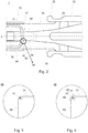
- Fig. 2 schematically shows an interrupter unit 1 for a gas blast circuit breaker. It has a central axis A. Only a main section of the unit is shown for illustrational purposes, omitting e.g. a drive unit.
- the interrupter unit comprises a first contact portion 10 with the arcing contact 12, typically, but not necessarily being a tulip type.
- a second contact portion 20 comprises a cylinder shaft 22 and the pin contact 25, which is shown in a state after an interrupting process.
- a nozzle 30 comprises an insulating material, e.g. PTFE, and is fixed to the first contact portion 10.
- the nozzle has a first section 32 surrounding the arcing contact 12, an intermediate cylindrical section 34 and a divergent section 36.
- a heating channel 40 having a circumferential opening 42 leading into the nozzle 30.
- a compressed gas is guided into an arcing zone 50 between the arcing contact 12 and the pin contact 25 during an opening operation of the interrupter unit 1.
- circumferential edge region 46 In the region of the circumferential opening 42 of the heating channel 40, there is a circumferential edge region 46 between a first side wall 60 of the heating channel 40, which first side wall 60 is oriented under an angle to the central axis A, and a wall of the intermediate cylindrical section 34 of the nozzle 30.
- the circumferential edge region 46 may have, according to embodiments, different configurations. They share the feature that at least one edge 47 with an effective or exact radius of at most 2 mm is provided in the edge region 46.
- edge region 46 Various options for the configuration of the edge region 46 are provided below, described with respect to Fig. 3 to Fig. 6 .
- the edge region 46 is shown having an edge 47 with an effective radius r.
- r is in embodiments about 2.0 mm or less, more preferably 1.5 mm or less and most preferably 1.0 mm or less.
- the edge 47 fosters the axial propagation of a discharge during an interrupting action.
- the circumferential edge region 46 comprises three neighbouring faces 61, 62, 63.
- the neighbouring faces 61, 62, 63 are at least partially circumferential around central axis A of the interrupter unit.
- the three, or in other options at least two, neighbouring at least partially circumferential faces 61, 62, 63 together are part of the edge region 46 between the first side wall 60 of the heating channel 40 and the wall of the cylindrical section 34 of the nozzle 30. From their combined inclination, an effective radius r results, which is about 2.0 mm or less, more preferably 1.5 mm or less and most preferably 1.0 mm or less.
- the effective radius r is herein also called enveloping radius r.
- an enveloping radius r may be present herein in the case of a non-circular shape (in a cross-sectional view) of the edge between the first side wall 60 of the heating channel 40 and the wall of the cylindrical section 34 of the nozzle 30, as shown in Fig. 4 .
- the enveloping radius is defined as a radius which approximates the real shape of the edge region.
- the enveloping radius is shown as arrow r, wherein the tip of the arrow ends at the "edge" between neighbouring face 61 and neighbouring face 62.
- the enveloping radius r may be regarded as the smallest radius which may be fitted to an (irregular, i.e. non-circular) edge so that each location on the edge curve (in a cross-sectional view) is enveloped by the curve of the radius r. While this is exemplarily shown in Fig. 4 only, the concept of the enveloping radius is also applicable to other embodiments described herein. In the case of a principally (quarter-)circular shape of the edge, the enveloping radius is identical to the exact radius.
- the edge region 46 comprises a plurality of steps 56.
- each step 56 has an edge 47 which has an effective or exact radius of significantly less than 2.0 mm, in particular the edges 47 having effective radii or exact radii equal to or smaller than 1.5 mm and preferred equal to or smaller than 1.0 mm and most preferred equal to or smaller than 0.5 mm.
- the steps 56 each comprise step segments with alternatingly substantially parallel (v) and substantially perpendicular (h) orientation and a respective dimension - whereby the orientation may be given with respect to an end portion of the first side wall 60 of the heating channel 40, or vice versa (i.e. with exchanging perpendicular (v) and parallel (h)) with respect to the side wall of the cylindrical section 34 of the nozzle 30.
- the step segments each have a length of at most 5 mm, more preferably at most 4 mm or at most 3 mm or at most about 2.5 mm, in the substantially parallel with respect to the first side wall (v) (or radial) direction; and at most about 5 mm, more preferably at most about 2.5 mm, in substantially perpendicular with respect to the first side wall (h) (or axial) direction ("about” meaning +/- 10 percent in this disclosure and including disclosure of "exact").
- substantially radial (v) (or parallel with respect to the first side wall 60) is intended to include a range of the inclination with respect to the central axis A of the interrupter unit from 70° to 110°, even more from 60° to 120°.
- Substantially axial (h) (or perpendicular with respect to the first side wall 60) comprises, according to embodiments, a range of inclination with respect to the central axis A from -20° to 20°, even more from -30° to 30°.
- An example for radial (v) segments with an angle different from 90° is shown in Fig. 6 , where a kind of saw-tooth profile results, which may be advantageous in view of the additional reduction of surface currents.
- step segments may have different sizes with respect to each other, meaning a difference between axial (h) and radial (v) segments of the same step 56. Further, steps 56 with varying dimensions between each other may be present.
- the steps 56 are provided such that the stair formed by the steps has a pitch line with an inclination angle a (see Fig. 5 and Fig. 6 ) of at least about 30° with respect to the central axis A (horizontal axis in the Fig. 5 and 6 ). It has been found out experimentally that the arcing detachment is sufficient when the inclination angle a is 30° or larger, more preferably 45° or larger.
- the size of the individual steps may vary, such that the steps 56 form a stair which does not have a constant inclination angle a as in Fig. 5 and Fig. 6 .
- the inclination angle a varies along a path (in the drawing pane, such as in Fig. 5 ) connecting the edges 47 of the different steps 56.
- the inclination angle has a variation depending on the location at which it is determined.
- the maximum inclination angle a measured along the path between the edge 47 of the first step 56 - by definition close to the nozzle 33 - and the edge 47 of the last step 56 - by definition close to the heating channel 40 - is at least at one location on the path at least about 30°. That is, at other locations along the path, the inclination can be smaller than 30°.
- a graph may be drawn connecting the edges 47 of the steps 56 using a least mean square procedure.
- the present configuration allows the use of an alternative gas to SF 6 (e.g., as described in WO2014154292 A1 ) having a global warming potential lower than the one of SF 6 .
- the insulation gas may for example comprise at least one background gas component selected from the group consisting of CO 2 , O 2 , N 2 , H, air, N 2 O, in a mixture with a hydrocarbon or an organofluorine compound.
- the dielectric insulating medium may comprise dry air or technical air.
- the dielectric insulating medium may in particular comprise an organofluorine compound selected from the group consisting of: a fluoroether, an oxirane, a fluoroamine, a fluoroketone, a fluoroolefin, a fluoronitrile, and mixtures and/or decomposition products thereof.
- the insulation gas may comprise as a hydrocarbon at least CH 4 , a perfluorinated and/or partially hydrogenated organofluorine compound, and mixtures thereof.
- the organofluorine compound is preferably selected from the group consisting of: a fluorocarbon, a fluoroether, a fluoroamine, a fluoronitrile, and a fluoroketone; and preferably is a fluoroketone and/or a fluoroether, more preferably a perfluoroketone and/or a hydro fluoroether, more preferably a perfluoroketone having from 4 to 12 carbon atoms and even more preferably a perfluoroketone having 4, 5 or 6 carbon atoms.
- the insulation gas preferably comprises the fluoroketone mixed with air or an air component such as N 2 , O 2 , and/or CO 2 .
- the fluoronitrile mentioned above is a perfluoronitrile, in particular a perfluoronitrile containing two carbon atoms, and/or three carbon atoms, and/or four carbon atoms. More particularly, the fluoronitrile can be a perfluoro-alkylnitrile, specifically perfluoroacetonitrile, perfluoropropionitrile (C2F5CN) and/or perfluorobutyronitrile (C3F7CN).
- the fluoronitrile can be perfluoro-isobutyronitrile (according to formula (CF3)2CFCN) and/or perfluoro-2-methoxy-propanenitrile (according to formula CF3CF(OCF3)CN).
- perfluoroiso-butyronitrile is particularly preferred due to its low toxicity.
Landscapes
- Circuit Breakers (AREA)
Claims (15)
- Unité rupteur (1) pour un disjoncteur à gaz comprimé, présentant un axe central A, comprenant :une première partie de contact (10) présentant un contact d'arc (12) ;une deuxième partie de contact (20) comprenant un contact d'arc conjugué (25), en particulier un contact à broche (25) ;une buse (30), comprenant un matériau isolant et fixée à la première partie de contact (10), la buse (30) présentant un premier tronçon (32) entourant le contact d'arc (12), un tronçon intermédiaire cylindrique (34) le long de l'axe central A et un tronçon divergent (36), etun canal de chauffage (40) étant ménagé et présentant une ouverture au moins partiellement circonférentielle (42) menant dans la buse (30), de manière à guider un gaz comprimé jusque dans une zone (50) entre le contact d'arc (12) et le contact à broche (25) au cours d'une opération d'ouverture de l'unité rupteur (1) ; une région de bord au moins partiellement circonférentielle (46) étant ménagée dans la région de l'ouverture au moins partiellement circonférentielle (42) du canal de chauffage (40), entre une première paroi latérale (60) du canal de chauffage (40), orientée selon un angle avec l'axe central A, et une paroi du tronçon intermédiaire cylindrique (34) de la buse (30),caractérisée en ce quela région de bord au moins partiellement circonférentielle (46) comprend au moins un bord (47) pourvu d'un rayon enveloppant ou d'un rayon exact d'au plus 2 mm, en particulier pourvu d'un rayon enveloppant ou d'un rayon exact inférieur ou égal à 1,5 mm et, idéalement, inférieur ou égale à 1,0 mm.
- Unité rupteur selon la revendication 1, dans laquelle la région de bord circonférentielle (46) comprend au moins deux faces voisines au moins partiellement circonférentielles (61, 62, 63), les au moins deux faces voisines au moins partiellement circonférentielles (61, 62, 63) faisant conjointement partie du bord (47) entre la première paroi latérale (60) du canal de chauffage (40) et la paroi du tronçon cylindrique (34) de la buse (30), et le rayon enveloppant du bord (47) étant formé entre la première paroi latérale (60) du canal de chauffage (40) et la paroi du tronçon cylindrique (34) de la buse (30).
- Unité rupteur selon les revendications 1 ou 2, dans laquelle la région de bord (46) comprend une pluralité de gradins (56), chaque gradin (56) comprenant un bord (47) présentant le rayon enveloppant ou le rayon exact, en particulier les bords (47) présentant des rayons enveloppants ou des rayons exacts inférieurs ou égaux à 1,5 mm et, de préférence, inférieurs ou égaux à 1,0 mm et, idéalement, inférieurs ou égaux à 0,5 mm.
- Unité rupteur selon la revendication 3, dans laquelle les gradins (56) comprennent chacun des segments de gradin pourvus d'une orientation en alternance sensiblement parallèle (v), en particulier parallèle (v), et sensiblement perpendiculaire (h), en particulier perpendiculaire (h), par rapport à une partie extrémité de la première paroi latérale (60) du canal de chauffage (40) et, en particulier, dans laquelle les segments de gradin présentent chacun une longueur inférieure à 5 mm, de préférence encore d'au plus 4 mm ou d'au plus 3 mm, dans la direction sensiblement parallèle ou exactement parallèle (v) et dans la direction sensiblement perpendiculaire ou exactement perpendiculaire (h) par rapport à une partie extrémité de la première paroi latérale (60) du canal de chauffage (40), sensiblement parallèle (v) étant définie de manière à inclure une plage de l'inclinaison par rapport à l'axe central A de l'unité rupteur allant de 60° à 120°, plus particulièrement allant de 70° à 110°, et sensiblement perpendiculaire (h) étant définie de manière à inclure une plage d'inclinaison par rapport à l'axe central A allant de -30 ° à 30°, particulièrement allant de -20° à 20°.
- Unité rupteur selon la revendication 3 ou 4, dans laquelle les gradins (56) comprennent chacun des segments de gradin pourvus d'une orientation en alternance sensiblement perpendiculaire (v) et sensiblement parallèle (h) par rapport à la paroi latérale du tronçon cylindrique (34) de la buse (30) et, en particulier, dans laquelle les segments de gradin présentent chacun une longueur de moins de 5 mm, de préférence encore d'au plus 4 mm ou d'au plus 3 mm, dans la direction sensiblement perpendiculaire (v) et dans la direction sensiblement parallèle (h) par rapport à la paroi latérale du tronçon cylindrique (34) de la buse (30), sensiblement perpendiculaire (v) étant définie de manière à inclure une plage de l'inclinaison par rapport à l'axe central A de l'unité rupteur allant de 60° à 120°, plus particulièrement allant de 70° à 110°, et sensiblement parallèle (h) étant définie de manière à inclure une plage d'inclinaison par rapport à l'axe central A allant de -30 ° à 30°, plus particulièrement allant de -20° à 20°.
- Unité rupteur selon l'une quelconque des revendications 3 à 5, dans laquelle les gradins (56) comprennent chacun des segments de gradin pourvus d'une orientation en alternance sensiblement radiale (v) et sensiblement axiale (h) par rapport à l'axe central A, en particulier dans laquelle les segments de gradin présentent chacun une longueur de moins de 5 mm, de préférence encore d'au plus 4 mm ou d'au plus 3 mm, dans la direction sensiblement radiale (v) et dans la direction sensiblement axiale (h), et dans laquelle sensiblement radiale (v) est définie de manière à inclure une plage de l'inclinaison par rapport à l'axe central A de l'unité rupteur allant de 60° à 120°, plus particulièrement allant de 70° à 110°, et sensiblement axiale (h) étant définie de manière à inclure une plage d'inclinaison par rapport à l'axe central A allant de - 30 ° à 30°, plus particulièrement allant de -20° à 20°, en particulier 0°.
- Unité rupteur selon l'une quelconque des revendications 3 à 6, dans laquelle des segments de gradin radiaux (v) et axiaux (h) présentent des longueurs différentes les uns par rapport aux autres.
- Unité rupteur selon l'une quelconque des revendications 3 à 7, dans laquelle des gradins (56) présentent des segments de gradin radiaux (v) et axiaux (h) pourvus de longueurs différentes par rapport à d'autres gradins.
- Unité rupteur selon l'une quelconque des revendications 3 à 8, dans laquelle la région de bord (46) comprend au moins trois gradins (56), et dans laquelle les gradins (56) sont ménagés de telle sorte que l'escalier formé par les gradins (56) présente une ligne de pente pourvue d'un angle d'inclinaison d'au moins environ 30°, plus particulièrement d'au moins 45°, par rapport à l'axe central A, ou dans laquelle, lorsque l'angle d'inclinaison de la ligne de pente de l'escalier formé par les gradins (56) présente une variation entre les gradins (56) du fait de l'agencement et/ou des longueurs des gradins individuels, un angle d'inclinaison maximal est d'au moins environ 30°, plus particulièrement est d'au moins 45°.
- Unité rupteur selon l'une quelconque des revendications précédentes, dans laquelle une paroi latérale (60) du canal de chauffage (40) est sensiblement radiale par rapport à l'axe central A à la jonction avec la buse (30), et dans laquelle sensiblement radiale est définie de manière à inclure une plage de l'inclinaison par rapport à l'axe central A de l'unité rupteur allant de 60° à 120°, plus particulièrement allant de 70° à 110°.
- Unité rupteur selon l'une quelconque des revendications précédentes, dans laquelle sensiblement radiale signifie radiale ou exactement radiale, sensiblement axiale signifie axiale ou exactement axiale, sensiblement parallèle signifie parallèle ou exactement parallèle et/ou sensiblement perpendiculaire signifie perpendiculaire ou exactement perpendiculaire.
- Unité rupteur selon l'une quelconque des revendications précédentes, laquelle unité rupteur possède une tension nominale de 70 kV ou plus.
- Disjoncteur doté d'une unité rupteur (1) selon l'une quelconque des revendications précédentes.
- Système GIS, comprenant un disjoncteur selon la revendication 13 ou une unité rupteur (1) selon l'une quelconque des revendications 1 à 12.
- Utilisation d'une unité rupteur (1) selon l'une quelconque des revendications 1 à 12 dans un disjoncteur.
Applications Claiming Priority (2)
| Application Number | Priority Date | Filing Date | Title |
|---|---|---|---|
| EP17158884 | 2017-03-02 | ||
| PCT/EP2018/055202 WO2018158440A1 (fr) | 2017-03-02 | 2018-03-02 | Disjoncteur haute tension à robustesse améliorée |
Publications (2)
| Publication Number | Publication Date |
|---|---|
| EP3590120A1 EP3590120A1 (fr) | 2020-01-08 |
| EP3590120B1 true EP3590120B1 (fr) | 2021-02-17 |
Family
ID=58213011
Family Applications (1)
| Application Number | Title | Priority Date | Filing Date |
|---|---|---|---|
| EP18707720.1A Active EP3590120B1 (fr) | 2017-03-02 | 2018-03-02 | Disjoncteur à haute tension avec robustnesse améliorée |
Country Status (3)
| Country | Link |
|---|---|
| EP (1) | EP3590120B1 (fr) |
| CN (1) | CN110402475B (fr) |
| WO (1) | WO2018158440A1 (fr) |
Family Cites Families (7)
| Publication number | Priority date | Publication date | Assignee | Title |
|---|---|---|---|---|
| JPS61188825A (ja) * | 1985-02-15 | 1986-08-22 | 株式会社日立製作所 | パツフア式ガス遮断器 |
| DE19936987C1 (de) * | 1999-07-30 | 2001-01-25 | Siemens Ag | Hochspannungsschalter mit Lichtbogenkontakten und einer Elektrode |
| DE19948687C1 (de) * | 1999-09-30 | 2001-02-15 | Siemens Ag | Hochspannungsleistungsschalter |
| WO2013153110A1 (fr) * | 2012-04-11 | 2013-10-17 | Abb Technology Ag | Disjoncteur |
| CN102938349B (zh) * | 2012-11-08 | 2014-12-24 | 上海思源高压开关有限公司 | 高压气体断路器 |
| CN105283939B (zh) | 2013-03-28 | 2017-07-07 | Abb 技术有限公司 | 开关组件、包括开关组件的开关设备、包括开关装置的开关设备和冷却方法 |
| EP2887367A1 (fr) * | 2013-12-19 | 2015-06-24 | ABB Technology AB | Disjoncteur haute tension isolé au gaz |
-
2018
- 2018-03-02 EP EP18707720.1A patent/EP3590120B1/fr active Active
- 2018-03-02 CN CN201880015368.1A patent/CN110402475B/zh active Active
- 2018-03-02 WO PCT/EP2018/055202 patent/WO2018158440A1/fr not_active Ceased
Non-Patent Citations (1)
| Title |
|---|
| None * |
Also Published As
| Publication number | Publication date |
|---|---|
| CN110402475A (zh) | 2019-11-01 |
| CN110402475B (zh) | 2021-10-15 |
| WO2018158440A1 (fr) | 2018-09-07 |
| EP3590120A1 (fr) | 2020-01-08 |
Similar Documents
| Publication | Publication Date | Title |
|---|---|---|
| US11699559B2 (en) | Device for interrupting non-short circuit currents only, in particular disconnector or earthing switch | |
| RU2738087C2 (ru) | Изолированный газом выключатель нагрузки низкого или среднего напряжения | |
| WO2013153110A1 (fr) | Disjoncteur | |
| EP3477675B1 (fr) | Commutateur moyenne tension à isolation gazeuse comportant un dispositif de protection | |
| US10991528B2 (en) | Gas-insulated load break switch and switchgear comprising a gas-insulated load break switch | |
| US12482618B2 (en) | Electrical switching device | |
| EP3590120B1 (fr) | Disjoncteur à haute tension avec robustnesse améliorée | |
| EP3261107A1 (fr) | Commutateur de basse ou moyenne tension à isolation gazeuse avec dispositif de turbulence | |
| EP4246548A1 (fr) | Unité d'interrupteur pour dispositif haute ou moyenne tension isolé au gaz et dispositif haute ou moyenne tension isolé au gaz | |
| EP4383306B1 (fr) | Unité d'interrupteur pour dispositif à haute ou moyenne tension isolé par gaz | |
| EP2827353A1 (fr) | Dispositif de commutation électrique | |
| EP2837011B1 (fr) | Disjoncteur | |
| EP4738416A1 (fr) | Coupe circuit | |
| EP4117006B1 (fr) | Disjoncteur haute ou moyenne tension isolé au gaz | |
| EP3826042B1 (fr) | Contact tulipe d'amorçage d'arc avec fentes de flux optimisé et fonctionnalité de détente de contraintes intégrée | |
| WO2026093467A1 (fr) | Disjoncteur | |
| WO2024199809A1 (fr) | Système de contact de sectionneur à décharge contrôlée | |
| WO2024200784A1 (fr) | Système de contact de sectionneur à décharge contrôlée |
Legal Events
| Date | Code | Title | Description |
|---|---|---|---|
| STAA | Information on the status of an ep patent application or granted ep patent |
Free format text: STATUS: UNKNOWN |
|
| STAA | Information on the status of an ep patent application or granted ep patent |
Free format text: STATUS: THE INTERNATIONAL PUBLICATION HAS BEEN MADE |
|
| PUAI | Public reference made under article 153(3) epc to a published international application that has entered the european phase |
Free format text: ORIGINAL CODE: 0009012 |
|
| STAA | Information on the status of an ep patent application or granted ep patent |
Free format text: STATUS: REQUEST FOR EXAMINATION WAS MADE |
|
| 17P | Request for examination filed |
Effective date: 20190813 |
|
| AK | Designated contracting states |
Kind code of ref document: A1 Designated state(s): AL AT BE BG CH CY CZ DE DK EE ES FI FR GB GR HR HU IE IS IT LI LT LU LV MC MK MT NL NO PL PT RO RS SE SI SK SM TR |
|
| AX | Request for extension of the european patent |
Extension state: BA ME |
|
| DAV | Request for validation of the european patent (deleted) | ||
| DAX | Request for extension of the european patent (deleted) | ||
| RAP1 | Party data changed (applicant data changed or rights of an application transferred) |
Owner name: ABB POWER GRIDS SWITZERLAND AG |
|
| GRAP | Despatch of communication of intention to grant a patent |
Free format text: ORIGINAL CODE: EPIDOSNIGR1 |
|
| STAA | Information on the status of an ep patent application or granted ep patent |
Free format text: STATUS: GRANT OF PATENT IS INTENDED |
|
| INTG | Intention to grant announced |
Effective date: 20200918 |
|
| GRAS | Grant fee paid |
Free format text: ORIGINAL CODE: EPIDOSNIGR3 |
|
| GRAA | (expected) grant |
Free format text: ORIGINAL CODE: 0009210 |
|
| STAA | Information on the status of an ep patent application or granted ep patent |
Free format text: STATUS: THE PATENT HAS BEEN GRANTED |
|
| AK | Designated contracting states |
Kind code of ref document: B1 Designated state(s): AL AT BE BG CH CY CZ DE DK EE ES FI FR GB GR HR HU IE IS IT LI LT LU LV MC MK MT NL NO PL PT RO RS SE SI SK SM TR |
|
| REG | Reference to a national code |
Ref country code: GB Ref legal event code: FG4D |
|
| REG | Reference to a national code |
Ref country code: CH Ref legal event code: EP |
|
| REG | Reference to a national code |
Ref country code: DE Ref legal event code: R096 Ref document number: 602018012655 Country of ref document: DE |
|
| REG | Reference to a national code |
Ref country code: AT Ref legal event code: REF Ref document number: 1362563 Country of ref document: AT Kind code of ref document: T Effective date: 20210315 |
|
| REG | Reference to a national code |
Ref country code: IE Ref legal event code: FG4D |
|
| REG | Reference to a national code |
Ref country code: LT Ref legal event code: MG9D |
|
| REG | Reference to a national code |
Ref country code: NL Ref legal event code: MP Effective date: 20210217 |
|
| PG25 | Lapsed in a contracting state [announced via postgrant information from national office to epo] |
Ref country code: BG Free format text: LAPSE BECAUSE OF FAILURE TO SUBMIT A TRANSLATION OF THE DESCRIPTION OR TO PAY THE FEE WITHIN THE PRESCRIBED TIME-LIMIT Effective date: 20210517 Ref country code: FI Free format text: LAPSE BECAUSE OF FAILURE TO SUBMIT A TRANSLATION OF THE DESCRIPTION OR TO PAY THE FEE WITHIN THE PRESCRIBED TIME-LIMIT Effective date: 20210217 Ref country code: GR Free format text: LAPSE BECAUSE OF FAILURE TO SUBMIT A TRANSLATION OF THE DESCRIPTION OR TO PAY THE FEE WITHIN THE PRESCRIBED TIME-LIMIT Effective date: 20210518 Ref country code: HR Free format text: LAPSE BECAUSE OF FAILURE TO SUBMIT A TRANSLATION OF THE DESCRIPTION OR TO PAY THE FEE WITHIN THE PRESCRIBED TIME-LIMIT Effective date: 20210217 Ref country code: LT Free format text: LAPSE BECAUSE OF FAILURE TO SUBMIT A TRANSLATION OF THE DESCRIPTION OR TO PAY THE FEE WITHIN THE PRESCRIBED TIME-LIMIT Effective date: 20210217 Ref country code: PT Free format text: LAPSE BECAUSE OF FAILURE TO SUBMIT A TRANSLATION OF THE DESCRIPTION OR TO PAY THE FEE WITHIN THE PRESCRIBED TIME-LIMIT Effective date: 20210617 Ref country code: NO Free format text: LAPSE BECAUSE OF FAILURE TO SUBMIT A TRANSLATION OF THE DESCRIPTION OR TO PAY THE FEE WITHIN THE PRESCRIBED TIME-LIMIT Effective date: 20210517 |
|
| REG | Reference to a national code |
Ref country code: AT Ref legal event code: MK05 Ref document number: 1362563 Country of ref document: AT Kind code of ref document: T Effective date: 20210217 |
|
| PG25 | Lapsed in a contracting state [announced via postgrant information from national office to epo] |
Ref country code: SE Free format text: LAPSE BECAUSE OF FAILURE TO SUBMIT A TRANSLATION OF THE DESCRIPTION OR TO PAY THE FEE WITHIN THE PRESCRIBED TIME-LIMIT Effective date: 20210217 Ref country code: NL Free format text: LAPSE BECAUSE OF FAILURE TO SUBMIT A TRANSLATION OF THE DESCRIPTION OR TO PAY THE FEE WITHIN THE PRESCRIBED TIME-LIMIT Effective date: 20210217 Ref country code: LV Free format text: LAPSE BECAUSE OF FAILURE TO SUBMIT A TRANSLATION OF THE DESCRIPTION OR TO PAY THE FEE WITHIN THE PRESCRIBED TIME-LIMIT Effective date: 20210217 Ref country code: PL Free format text: LAPSE BECAUSE OF FAILURE TO SUBMIT A TRANSLATION OF THE DESCRIPTION OR TO PAY THE FEE WITHIN THE PRESCRIBED TIME-LIMIT Effective date: 20210217 Ref country code: RS Free format text: LAPSE BECAUSE OF FAILURE TO SUBMIT A TRANSLATION OF THE DESCRIPTION OR TO PAY THE FEE WITHIN THE PRESCRIBED TIME-LIMIT Effective date: 20210217 |
|
| PG25 | Lapsed in a contracting state [announced via postgrant information from national office to epo] |
Ref country code: IS Free format text: LAPSE BECAUSE OF FAILURE TO SUBMIT A TRANSLATION OF THE DESCRIPTION OR TO PAY THE FEE WITHIN THE PRESCRIBED TIME-LIMIT Effective date: 20210617 |
|
| PG25 | Lapsed in a contracting state [announced via postgrant information from national office to epo] |
Ref country code: SM Free format text: LAPSE BECAUSE OF FAILURE TO SUBMIT A TRANSLATION OF THE DESCRIPTION OR TO PAY THE FEE WITHIN THE PRESCRIBED TIME-LIMIT Effective date: 20210217 Ref country code: AT Free format text: LAPSE BECAUSE OF FAILURE TO SUBMIT A TRANSLATION OF THE DESCRIPTION OR TO PAY THE FEE WITHIN THE PRESCRIBED TIME-LIMIT Effective date: 20210217 Ref country code: EE Free format text: LAPSE BECAUSE OF FAILURE TO SUBMIT A TRANSLATION OF THE DESCRIPTION OR TO PAY THE FEE WITHIN THE PRESCRIBED TIME-LIMIT Effective date: 20210217 Ref country code: CZ Free format text: LAPSE BECAUSE OF FAILURE TO SUBMIT A TRANSLATION OF THE DESCRIPTION OR TO PAY THE FEE WITHIN THE PRESCRIBED TIME-LIMIT Effective date: 20210217 |
|
| REG | Reference to a national code |
Ref country code: CH Ref legal event code: PL |
|
| REG | Reference to a national code |
Ref country code: DE Ref legal event code: R097 Ref document number: 602018012655 Country of ref document: DE |
|
| PG25 | Lapsed in a contracting state [announced via postgrant information from national office to epo] |
Ref country code: DK Free format text: LAPSE BECAUSE OF FAILURE TO SUBMIT A TRANSLATION OF THE DESCRIPTION OR TO PAY THE FEE WITHIN THE PRESCRIBED TIME-LIMIT Effective date: 20210217 Ref country code: SK Free format text: LAPSE BECAUSE OF FAILURE TO SUBMIT A TRANSLATION OF THE DESCRIPTION OR TO PAY THE FEE WITHIN THE PRESCRIBED TIME-LIMIT Effective date: 20210217 Ref country code: RO Free format text: LAPSE BECAUSE OF FAILURE TO SUBMIT A TRANSLATION OF THE DESCRIPTION OR TO PAY THE FEE WITHIN THE PRESCRIBED TIME-LIMIT Effective date: 20210217 Ref country code: MC Free format text: LAPSE BECAUSE OF FAILURE TO SUBMIT A TRANSLATION OF THE DESCRIPTION OR TO PAY THE FEE WITHIN THE PRESCRIBED TIME-LIMIT Effective date: 20210217 |
|
| REG | Reference to a national code |
Ref country code: BE Ref legal event code: MM Effective date: 20210331 |
|
| PLBE | No opposition filed within time limit |
Free format text: ORIGINAL CODE: 0009261 |
|
| STAA | Information on the status of an ep patent application or granted ep patent |
Free format text: STATUS: NO OPPOSITION FILED WITHIN TIME LIMIT |
|
| RAP4 | Party data changed (patent owner data changed or rights of a patent transferred) |
Owner name: HITACHI ENERGY SWITZERLAND AG |
|
| 26N | No opposition filed |
Effective date: 20211118 |
|
| PG25 | Lapsed in a contracting state [announced via postgrant information from national office to epo] |
Ref country code: ES Free format text: LAPSE BECAUSE OF FAILURE TO SUBMIT A TRANSLATION OF THE DESCRIPTION OR TO PAY THE FEE WITHIN THE PRESCRIBED TIME-LIMIT Effective date: 20210217 Ref country code: IE Free format text: LAPSE BECAUSE OF NON-PAYMENT OF DUE FEES Effective date: 20210302 Ref country code: LU Free format text: LAPSE BECAUSE OF NON-PAYMENT OF DUE FEES Effective date: 20210302 Ref country code: LI Free format text: LAPSE BECAUSE OF NON-PAYMENT OF DUE FEES Effective date: 20210331 Ref country code: AL Free format text: LAPSE BECAUSE OF FAILURE TO SUBMIT A TRANSLATION OF THE DESCRIPTION OR TO PAY THE FEE WITHIN THE PRESCRIBED TIME-LIMIT Effective date: 20210217 Ref country code: CH Free format text: LAPSE BECAUSE OF NON-PAYMENT OF DUE FEES Effective date: 20210331 |
|
| PG25 | Lapsed in a contracting state [announced via postgrant information from national office to epo] |
Ref country code: SI Free format text: LAPSE BECAUSE OF FAILURE TO SUBMIT A TRANSLATION OF THE DESCRIPTION OR TO PAY THE FEE WITHIN THE PRESCRIBED TIME-LIMIT Effective date: 20210217 |
|
| PG25 | Lapsed in a contracting state [announced via postgrant information from national office to epo] |
Ref country code: IT Free format text: LAPSE BECAUSE OF FAILURE TO SUBMIT A TRANSLATION OF THE DESCRIPTION OR TO PAY THE FEE WITHIN THE PRESCRIBED TIME-LIMIT Effective date: 20210217 |
|
| PG25 | Lapsed in a contracting state [announced via postgrant information from national office to epo] |
Ref country code: IS Free format text: LAPSE BECAUSE OF FAILURE TO SUBMIT A TRANSLATION OF THE DESCRIPTION OR TO PAY THE FEE WITHIN THE PRESCRIBED TIME-LIMIT Effective date: 20210617 |
|
| REG | Reference to a national code |
Ref country code: DE Ref legal event code: R081 Ref document number: 602018012655 Country of ref document: DE Owner name: HITACHI ENERGY SWITZERLAND AG, CH Free format text: FORMER OWNER: ABB POWER GRIDS SWITZERLAND AG, BADEN, CH Ref country code: DE Ref legal event code: R081 Ref document number: 602018012655 Country of ref document: DE Owner name: HITACHI ENERGY LTD, CH Free format text: FORMER OWNER: ABB POWER GRIDS SWITZERLAND AG, BADEN, CH |
|
| PG25 | Lapsed in a contracting state [announced via postgrant information from national office to epo] |
Ref country code: BE Free format text: LAPSE BECAUSE OF NON-PAYMENT OF DUE FEES Effective date: 20210331 |
|
| GBPC | Gb: european patent ceased through non-payment of renewal fee |
Effective date: 20220302 |
|
| PG25 | Lapsed in a contracting state [announced via postgrant information from national office to epo] |
Ref country code: GB Free format text: LAPSE BECAUSE OF NON-PAYMENT OF DUE FEES Effective date: 20220302 |
|
| PG25 | Lapsed in a contracting state [announced via postgrant information from national office to epo] |
Ref country code: CY Free format text: LAPSE BECAUSE OF FAILURE TO SUBMIT A TRANSLATION OF THE DESCRIPTION OR TO PAY THE FEE WITHIN THE PRESCRIBED TIME-LIMIT Effective date: 20210217 |
|
| P01 | Opt-out of the competence of the unified patent court (upc) registered |
Effective date: 20230527 |
|
| PG25 | Lapsed in a contracting state [announced via postgrant information from national office to epo] |
Ref country code: HU Free format text: LAPSE BECAUSE OF FAILURE TO SUBMIT A TRANSLATION OF THE DESCRIPTION OR TO PAY THE FEE WITHIN THE PRESCRIBED TIME-LIMIT; INVALID AB INITIO Effective date: 20180302 |
|
| REG | Reference to a national code |
Ref country code: DE Ref legal event code: R082 Ref document number: 602018012655 Country of ref document: DE Representative=s name: DENNEMEYER & ASSOCIATES RECHTSANWALTSGESELLSCH, DE Ref country code: DE Ref legal event code: R082 Ref document number: 602018012655 Country of ref document: DE Representative=s name: DENNEMEYER & ASSOCIATES S.A., DE Ref country code: DE Ref legal event code: R081 Ref document number: 602018012655 Country of ref document: DE Owner name: HITACHI ENERGY LTD, CH Free format text: FORMER OWNER: HITACHI ENERGY SWITZERLAND AG, BADEN, CH |
|
| PG25 | Lapsed in a contracting state [announced via postgrant information from national office to epo] |
Ref country code: MK Free format text: LAPSE BECAUSE OF FAILURE TO SUBMIT A TRANSLATION OF THE DESCRIPTION OR TO PAY THE FEE WITHIN THE PRESCRIBED TIME-LIMIT Effective date: 20210217 |
|
| PG25 | Lapsed in a contracting state [announced via postgrant information from national office to epo] |
Ref country code: MT Free format text: LAPSE BECAUSE OF FAILURE TO SUBMIT A TRANSLATION OF THE DESCRIPTION OR TO PAY THE FEE WITHIN THE PRESCRIBED TIME-LIMIT Effective date: 20210217 |
|
| REG | Reference to a national code |
Ref country code: DE Ref legal event code: R082 Ref document number: 602018012655 Country of ref document: DE Representative=s name: DENNEMEYER & ASSOCIATES RECHTSANWALTSGESELLSCH, DE |
|
| PG25 | Lapsed in a contracting state [announced via postgrant information from national office to epo] |
Ref country code: TR Free format text: LAPSE BECAUSE OF FAILURE TO SUBMIT A TRANSLATION OF THE DESCRIPTION OR TO PAY THE FEE WITHIN THE PRESCRIBED TIME-LIMIT Effective date: 20210217 |
|
| PGFP | Annual fee paid to national office [announced via postgrant information from national office to epo] |
Ref country code: DE Payment date: 20260319 Year of fee payment: 9 |
|
| PGFP | Annual fee paid to national office [announced via postgrant information from national office to epo] |
Ref country code: FR Payment date: 20260320 Year of fee payment: 9 |