EP3590183B1 - Transformateur de tension, procédé de fonctionnement de celui-ci et programme informatique - Google Patents
Transformateur de tension, procédé de fonctionnement de celui-ci et programme informatique Download PDFInfo
- Publication number
- EP3590183B1 EP3590183B1 EP18708394.4A EP18708394A EP3590183B1 EP 3590183 B1 EP3590183 B1 EP 3590183B1 EP 18708394 A EP18708394 A EP 18708394A EP 3590183 B1 EP3590183 B1 EP 3590183B1
- Authority
- EP
- European Patent Office
- Prior art keywords
- converter
- voltage converter
- voltage
- module
- transformer
- Prior art date
- Legal status (The legal status is an assumption and is not a legal conclusion. Google has not performed a legal analysis and makes no representation as to the accuracy of the status listed.)
- Active
Links
Images


Classifications
-
- H—ELECTRICITY
- H02—GENERATION; CONVERSION OR DISTRIBUTION OF ELECTRIC POWER
- H02M—APPARATUS FOR CONVERSION BETWEEN AC AND AC, BETWEEN AC AND DC, OR BETWEEN DC AND DC, AND FOR USE WITH MAINS OR SIMILAR POWER SUPPLY SYSTEMS; CONVERSION OF DC OR AC INPUT POWER INTO SURGE OUTPUT POWER; CONTROL OR REGULATION THEREOF
- H02M3/00—Conversion of DC power input into DC power output
- H02M3/22—Conversion of DC power input into DC power output with intermediate conversion into AC
- H02M3/24—Conversion of DC power input into DC power output with intermediate conversion into AC by static converters
- H02M3/28—Conversion of DC power input into DC power output with intermediate conversion into AC by static converters using discharge tubes with control electrode or semiconductor devices with control electrode to produce the intermediate AC
- H02M3/285—Single converters with a plurality of output stages connected in parallel
-
- H—ELECTRICITY
- H02—GENERATION; CONVERSION OR DISTRIBUTION OF ELECTRIC POWER
- H02M—APPARATUS FOR CONVERSION BETWEEN AC AND AC, BETWEEN AC AND DC, OR BETWEEN DC AND DC, AND FOR USE WITH MAINS OR SIMILAR POWER SUPPLY SYSTEMS; CONVERSION OF DC OR AC INPUT POWER INTO SURGE OUTPUT POWER; CONTROL OR REGULATION THEREOF
- H02M3/00—Conversion of DC power input into DC power output
- H02M3/01—Resonant DC/DC converters
-
- H—ELECTRICITY
- H02—GENERATION; CONVERSION OR DISTRIBUTION OF ELECTRIC POWER
- H02M—APPARATUS FOR CONVERSION BETWEEN AC AND AC, BETWEEN AC AND DC, OR BETWEEN DC AND DC, AND FOR USE WITH MAINS OR SIMILAR POWER SUPPLY SYSTEMS; CONVERSION OF DC OR AC INPUT POWER INTO SURGE OUTPUT POWER; CONTROL OR REGULATION THEREOF
- H02M3/00—Conversion of DC power input into DC power output
- H02M3/22—Conversion of DC power input into DC power output with intermediate conversion into AC
- H02M3/24—Conversion of DC power input into DC power output with intermediate conversion into AC by static converters
- H02M3/28—Conversion of DC power input into DC power output with intermediate conversion into AC by static converters using discharge tubes with control electrode or semiconductor devices with control electrode to produce the intermediate AC
- H02M3/325—Conversion of DC power input into DC power output with intermediate conversion into AC by static converters using discharge tubes with control electrode or semiconductor devices with control electrode to produce the intermediate AC using devices of a triode or a transistor type requiring continuous application of a control signal
- H02M3/335—Conversion of DC power input into DC power output with intermediate conversion into AC by static converters using discharge tubes with control electrode or semiconductor devices with control electrode to produce the intermediate AC using devices of a triode or a transistor type requiring continuous application of a control signal using semiconductor devices only
- H02M3/33569—Conversion of DC power input into DC power output with intermediate conversion into AC by static converters using discharge tubes with control electrode or semiconductor devices with control electrode to produce the intermediate AC using devices of a triode or a transistor type requiring continuous application of a control signal using semiconductor devices only having several active switching elements
- H02M3/33573—Full-bridge at primary side of an isolation transformer
-
- H—ELECTRICITY
- H02—GENERATION; CONVERSION OR DISTRIBUTION OF ELECTRIC POWER
- H02M—APPARATUS FOR CONVERSION BETWEEN AC AND AC, BETWEEN AC AND DC, OR BETWEEN DC AND DC, AND FOR USE WITH MAINS OR SIMILAR POWER SUPPLY SYSTEMS; CONVERSION OF DC OR AC INPUT POWER INTO SURGE OUTPUT POWER; CONTROL OR REGULATION THEREOF
- H02M1/00—Details of apparatus for conversion
- H02M1/0048—Circuits or arrangements for reducing losses
- H02M1/0054—Transistor switching losses
- H02M1/0058—Transistor switching losses by employing soft switching techniques, i.e. commutation of transistors when applied voltage is zero or when current flow is zero
-
- H—ELECTRICITY
- H02—GENERATION; CONVERSION OR DISTRIBUTION OF ELECTRIC POWER
- H02M—APPARATUS FOR CONVERSION BETWEEN AC AND AC, BETWEEN AC AND DC, OR BETWEEN DC AND DC, AND FOR USE WITH MAINS OR SIMILAR POWER SUPPLY SYSTEMS; CONVERSION OF DC OR AC INPUT POWER INTO SURGE OUTPUT POWER; CONTROL OR REGULATION THEREOF
- H02M1/00—Details of apparatus for conversion
- H02M1/0064—Magnetic structures combining different functions, e.g. storage, filtering or transformation
-
- H—ELECTRICITY
- H02—GENERATION; CONVERSION OR DISTRIBUTION OF ELECTRIC POWER
- H02M—APPARATUS FOR CONVERSION BETWEEN AC AND AC, BETWEEN AC AND DC, OR BETWEEN DC AND DC, AND FOR USE WITH MAINS OR SIMILAR POWER SUPPLY SYSTEMS; CONVERSION OF DC OR AC INPUT POWER INTO SURGE OUTPUT POWER; CONTROL OR REGULATION THEREOF
- H02M1/00—Details of apparatus for conversion
- H02M1/0067—Converter structures employing plural converter units, other than for parallel operation of the units on a single load
- H02M1/0074—Plural converter units whose inputs are connected in series
-
- H—ELECTRICITY
- H02—GENERATION; CONVERSION OR DISTRIBUTION OF ELECTRIC POWER
- H02M—APPARATUS FOR CONVERSION BETWEEN AC AND AC, BETWEEN AC AND DC, OR BETWEEN DC AND DC, AND FOR USE WITH MAINS OR SIMILAR POWER SUPPLY SYSTEMS; CONVERSION OF DC OR AC INPUT POWER INTO SURGE OUTPUT POWER; CONTROL OR REGULATION THEREOF
- H02M1/00—Details of apparatus for conversion
- H02M1/0067—Converter structures employing plural converter units, other than for parallel operation of the units on a single load
- H02M1/0077—Plural converter units whose outputs are connected in series
-
- H—ELECTRICITY
- H02—GENERATION; CONVERSION OR DISTRIBUTION OF ELECTRIC POWER
- H02M—APPARATUS FOR CONVERSION BETWEEN AC AND AC, BETWEEN AC AND DC, OR BETWEEN DC AND DC, AND FOR USE WITH MAINS OR SIMILAR POWER SUPPLY SYSTEMS; CONVERSION OF DC OR AC INPUT POWER INTO SURGE OUTPUT POWER; CONTROL OR REGULATION THEREOF
- H02M1/00—Details of apparatus for conversion
- H02M1/32—Means for protecting converters other than automatic disconnection
- H02M1/325—Means for protecting converters other than automatic disconnection with means for allowing continuous operation despite a fault, i.e. fault tolerant converters
-
- Y—GENERAL TAGGING OF NEW TECHNOLOGICAL DEVELOPMENTS; GENERAL TAGGING OF CROSS-SECTIONAL TECHNOLOGIES SPANNING OVER SEVERAL SECTIONS OF THE IPC; TECHNICAL SUBJECTS COVERED BY FORMER USPC CROSS-REFERENCE ART COLLECTIONS [XRACs] AND DIGESTS
- Y02—TECHNOLOGIES OR APPLICATIONS FOR MITIGATION OR ADAPTATION AGAINST CLIMATE CHANGE
- Y02B—CLIMATE CHANGE MITIGATION TECHNOLOGIES RELATED TO BUILDINGS, e.g. HOUSING, HOUSE APPLIANCES OR RELATED END-USER APPLICATIONS
- Y02B70/00—Technologies for an efficient end-user side electric power management and consumption
- Y02B70/10—Technologies improving the efficiency by using switched-mode power supplies [SMPS], i.e. efficient power electronics conversion e.g. power factor correction or reduction of losses in power supplies or efficient standby modes
Definitions
- the invention relates to a voltage converter according to the preamble of claim 1.
- the invention also relates to a method for operating such a voltage converter and a computer program for performing the method on a computer.
- Voltage converters are used to convert a high DC voltage into a low DC voltage or vice versa.
- the DC voltages i.e. the first DC voltage and the second DC voltage, can also be of the same size or essentially the same size if a voltage converter is to be used, e.g. for galvanic isolation between DC voltage networks.
- the present invention is based on a modular design of the voltage converter with a large number of converter modules, which has the advantage that appropriate connection of the converter modules on the primary and secondary sides (parallel connection / series connection) enables a suitable adaptation to the requirements of the DC voltages to be converted and the total component cost, especially for power semiconductors, can be kept comparatively moderate.
- the advantage of such modular systems is the low cost and the potentially higher efficiency of the system.
- the invention is based on the object of developing such a modular voltage converter in terms of functionality and scalability.
- the converter modules are each designed as a multiple active bridge, full-resonant topology, power source topology, impedance source topology or the like with a respective transformer connected between the primary side and the secondary side of a converter module, the transformers of the converter modules being magnetic to one another are coupled.
- the present invention therefore relates to voltage converters which are based on the functionality of a multiple active bridge or a similar converter technology that requires a transformer.
- a multiple active bridge can, for example, in the form of a dual active bridge, as in the U.S. 5,027,264 described, or a quadruple active bridge, whereby other topologies or technologies can also be used.
- Switched power semiconductors are used in this type of voltage converter. For energy transmission between the primary side and the secondary side, pulsed, square-wave signals are generated via the power semiconductors on both sides, ie primary side and secondary side, by clocked switching of the power semiconductors. The energy is transmitted via a phase shift between the signals on the primary side and the secondary side (phase shift modulation).
- An additional synergetic effect with the modular structure of the voltage converter is achieved in that the transformers of the converter modules are magnetically coupled to one another. In this way electrical power cannot can only be transmitted between the primary side and the secondary side within a converter module, but power transfer between the converter modules magnetically coupled to one another in this way is also possible. This can further improve the scalability, failure insensitivity and ease of repair of the system.
- the voltage converter is significantly improved with regard to the fault tolerance, the scalability of the transmittable voltage and power, and the ability to be repaired. Due to the modularity of the voltage converter, only the affected converter module or parts of it need to be replaced in the event of a defect.
- the modularity also provides redundancy, which makes it possible to continue operating the voltage converter in the event of a defect, for example in an individual converter module.
- the reliability is increased accordingly. A repair can then be carried out at a suitable time and does not necessarily have to be carried out immediately.
- maintenance is simplified overall due to the modularity.
- the high-frequency operation typical of a multiple active bridge means that the transformers required can also be kept small. Accordingly, they have a lower weight than conventional voltage converters, which simplifies the maintenance and replacement of components of the voltage converter and often makes repairs on site possible in the first place.
- the transformers can be designed without a core or with a magnetic core.
- the voltage converter can in particular be designed as a bidirectional voltage converter, which optionally converts the first DC voltage as an input voltage into the second DC voltage, which is then an output voltage, or processes the second DC voltage as an input voltage to provide the first DC voltage as an output voltage.
- the converter modules each have their own primary side and secondary side.
- the primary sides of the converter modules are assigned to the primary side of the voltage converter, and the secondary sides of the converter modules are assigned to the secondary side of the voltage converter.
- the invention is generally suitable for connecting medium-voltage or high-voltage systems.
- the invention is also suitable for galvanic isolation in DC voltage networks.
- Further fields of application are, for example, power-based transformers (solid state transformers), electric rail vehicles, charging stations for electric vehicles or the connection of battery systems.
- the magnetic coupling between the converter modules can be formed by a magnetic core that magnetically connects their transformers.
- a magnetic core can significantly increase the degree of coupling and thus the efficiency of the power transmission from one converter module to another converter module via the magnetically coupled transformers.
- the magnetic core is designed as a ring-shaped closed or at least substantially closed magnetic core. This allows the degree of coupling and thus the efficiency of the energy transmission to be increased further.
- transformers are formed by a large number of primary-side and secondary-side transformer windings which are arranged on a common magnetic core.
- This also allows a modular structure of the invention Voltage converter in relation to the transformers.
- the common magnetic core also enables cost advantages over separate magnetic cores.
- the individual converter modules can each be designed with their own transformers, the magnetically coupled transformers being mechanically detachably coupled with one another so that a single transformer or a single transformer winding can be exchanged. This further improves the ease of repair of the voltage converter according to the invention.
- the already mentioned common magnetic core of the transformer can itself again be of modular construction, i.e. from individual core modules. This also enables a partial replacement of the parts of the transformer in the event of a defect in a converter cell or a converter module. It is thus possible to remove and / or replace the corresponding converter cell and the associated part of the core, i.e. the corresponding core module.
- one, several or all of the converter modules themselves are again modular, in that such a converter module has a primary-side converter cell, which is connected to a primary-side transformer winding of the transformer of the converter module, and a secondary-side converter cell which is connected to a secondary-side transformer winding of the transformer of the converter module.
- a primary-side converter cell which is connected to a primary-side transformer winding of the transformer of the converter module
- a secondary-side converter cell which is connected to a secondary-side transformer winding of the transformer of the converter module.
- a converter cell can then optionally be used as a primary-side converter cell or secondary-side converter cell.
- a primary-side converter cell and a secondary-side converter cell can be one Converter module be designed identically.
- the power semiconductors of a converter cell can be interconnected as a full bridge (H bridge) or as a half bridge, for example.
- a converter cell can also have its own control device or at least part of a control device in order to control the power semiconductors and also to control higher-level control functions for the energy transfer between different converter modules or converter cells.
- the local control device of a converter cell can be connected to a central control device of the voltage converter, for example by means of data communication, in order to implement higher-level control functions and regulating functions of the voltage converter.
- the converter cell on the primary side and / or the converter cell on the secondary side can optionally be exchanged. This saves costs and material. In the event of a defect, a complete converter module does not have to be replaced. Instead, it is sufficient to replace a defective converter cell. It can in particular be provided that one or more primary-side and / or secondary-side converter cells can be removed and / or exchanged. In this case, the voltage converter can also continue to be operated without one or more converter cells that have been removed or replaced.
- the converter modules are connected to one another in series or in parallel on their primary side, and / or the converter modules are connected to one another in series or in parallel on their secondary side.
- the voltage converter can be adapted to the respective requirements of the primary side and the secondary side. If, for example, the first direct voltage is to be considerably greater than the second direct voltage, it is advantageous to connect the converter modules in series on the primary side and to connect them in parallel on the secondary side. In this way, the voltage on the primary side of a converter module is reduced by the series connection Values are reduced, while high currents can be processed on the secondary side due to the parallel connection.
- the voltage converter has a control device which is set up to control or regulate the transfer of electrical power from one converter module of the voltage converter to another converter module of the voltage converter or several other converter modules of the voltage converter according to a default value .
- a default value can be a fixed default value or a variable default value that is adapted depending on the operating state of the voltage converter.
- the default value can be determined, for example, from characteristic curves or characteristic curve fields.
- the load on the individual components can be influenced in the desired manner and the components can thus be protected from overload.
- the aging of the components of a converter cell or a converter module can also be controlled in a targeted manner. A higher load leads to faster aging than a lower load.
- the transfer of electrical power between converter modules or converter cells of the voltage converter is carried out according to an aging default value, which influences their aging by regulating the load on the individual components in a predetermined manner.
- control device is set up to deactivate this converter module in whole or in part during operation of the voltage converter in the event of a fault in a converter module occurring during operation of the voltage converter. To this way, the voltage converter can continue to operate even with such partial defects and thus does not fail.
- the repair can be scheduled at a suitable time.
- the reconfiguration can take place in such a way that a voltage converter, which was previously operated in a configuration as a dual active bridge, continues to be operated as a series resonant converter as a result of the reconfiguration.
- Another possibility for reconfiguration can be to switch the voltage converter, which initially acts bidirectionally, into a unidirectional mode, or to reconfigure a voltage converter in a full-bridge arrangement into a half-bridge arrangement plus voltage divider.
- the software of the voltage converter i.e. a computer program executing a method according to the invention in the voltage converter, controls the power flow between the converter cells depending on the state and the possibilities that exist after an error.
- control device is set up to deactivate a converter module to be deactivated only on the faulty side of the converter module, i.e. the primary side or the secondary side, and to continue to operate the other side. In this way, the reliability and availability of the system can be further increased.
- the aforementioned transfer of electrical power ie the power transfer, can take place in particular between the primary side and the secondary side of the voltage converter. According to an advantageous development of the invention provided that after a fault in a converter module has been detected, the operation of the voltage converter is continued, regardless of the primary or secondary side.
- the control device is set up to activate a converter module or a converter cell available as a reserve and to operate the voltage converter when the power requirement of the voltage converter increases and / or in the case of deactivation of a converter module or a part thereof to integrate.
- This can further increase the reliability of the system.
- one or more converter cells can be present as a reserve on the primary side, and one or more converter cells can also be present as a reserve on the secondary side.
- Entire converter modules can also be available as a reserve. These can be inactive as long as there is no increased power requirement and no defect occurs in the other converter modules.
- converter modules or converter cells present as a reserve it is also possible to periodically activate converter modules or converter cells present as a reserve and to integrate them into the operation of the voltage converter, even if there is no increased power requirement and no defects. In this case, other converter modules or converter cells can be switched off periodically and thus protected. This also makes it possible to periodically check the functionality of the converter modules or converter cells present as a reserve.
- the control device can have one computer or several computers, e.g. in the form of microcomputers or microcontrollers.
- the control device can comprise a central control device of the voltage converter.
- the control device can also be of modular design, in that individual local parts of the control device are present in the converter modules or the individual converter cells.
- the voltage converter according to the invention can thus be controlled in such a way that converter modules or converter cells can be expanded without further Interventions in the software of the control device is possible. Furthermore, a failure of a converter module or a converter cell can be compensated for by means of the software by another converter module or another converter cell.
- the magnetic coupling makes it possible to transfer electrical energy between all converter modules or all converter cells. Only additional converter modules or converter cells are required to expand the system, and the transformer arrangement can also be expanded by adding additional transformer windings on a common magnetic core. This creates a system that is scalable in terms of power and voltage.
- the power flow can be regulated centrally by a control device.
- control device executes one or more method steps for controlling or regulating the transmission of electrical power from one converter module of the voltage converter to another converter module of the voltage converter or several other converter modules of the voltage converter according to a default value of the voltage converter.
- the advantages explained above can also be realized in this way.
- the control device can also carry out the previously explained further method steps for which the control device is set up.
- a voltage converter can be implemented according to the fault ride-through principle, which on the one hand results from the use of the multi-turn transformer, which guarantees a connection between all active converter cells, and also from the fact that both the hardware and the software of the voltage converter can be built up to be fault-tolerant and self-healing.
- the hardware is reconfigurable due to the removability of part of the magnetic core of the transformer including the corresponding windings and the power semiconductors.
- the hardware is self-healing because, in the event of a fault, the functional parts of the system implement a different converter topology.
- the software ensures that the resulting voltage converter, for example with a converter cell, is less functional or at least continues to function after the reconfiguration.
- the in Figure 1 The voltage converter 1 shown has a primary side 10 and a secondary side 20.
- a first DC voltage 11 is applied to the primary side 10 and a second DC voltage 21 is applied to the secondary side 20. It is assumed by way of example that the first DC voltage 11 is considerably greater than the second DC voltage 21.
- the voltage converter 1 also has a multiplicity of converter modules 2 , in this case five pieces, each with its own primary side 12 and have their own secondary side 22.
- the primary sides 12 of the converter modules 2 are assigned to the primary side 10 of the voltage converter 1, and the secondary sides 22 of the converter modules 2 are also assigned to the secondary side 20 of the voltage converter 1.
- the converter modules 2 are connected in series on the primary side and connected in parallel on the secondary side.
- the converter modules 2 are each designed as multiple active bridges, for example as dual active bridges or quadruple active bridges, or other cells.
- the voltage converter 1 also has a control device 3, which has a computer and a computer program (software) stored in a memory of the control device 3. The function of the individual converter modules 2 is controlled in the desired manner via the control device 3.
- the Figure 2 shows the structure of a voltage converter according to Figure 1 with the individual converter modules in further detail.
- a converter module 2 has a primary-side converter cell 13 and a secondary-side converter cell 23.
- These converter cells can be constructed from power electronics 8 with any type of transistors and any topology.
- a "resonant tank” can be added to improve the duty cycle.
- the primary-side converter cell 13 is connected to the secondary-side converter cell 23 via a transformer 5.
- the transformer 5 has a primary-side transformer winding 14 which is connected to the primary-side converter cell 13, and a secondary-side transformer winding 24 which is connected to the secondary-side converter cell 23.
- the transformer 5 can have a magnetic core 6, for example in the form of an iron core.
- the individual converter cells 2 are each designed with their own transformers 5.
- the transformers 5 of the converter modules 2 are magnetically coupled to one another, which can be implemented, for example, in that the individual transformers 5 are arranged close to one another so that the distance between their magnetic cores 6 is very small and, for example, only has a small air gap, such as For example, an air gap that is common in transformers.
- the individual converter cells 13, 23 can be designed to be separately exchangeable, so that they can be replaced in the event of a defect or during maintenance.
- FIG. 11 shows another embodiment of the voltage converter in one with FIG Figure 2 comparable representation.
- the individual transformers are no longer designed as separate transformers, but rather as a transformer unit 5 which has a common magnetic core 7 on which the individual primary-side transformer windings 14 and the secondary-side transformer windings 24 are arranged.
- this solution is more cost-effective than the individual magnetic cores 6 of the Figure 2 .
- the Figure 4 shows the mode of operation of the voltage converter 1 according to the invention in the event of a defect in a converter cell, in this case the primary-side converter cell 13 shown above on the left.
- the system according to the invention has a particular fault tolerance as a central advantage.
- the voltage converter 1 can continue to operate by deactivating the defective converter cell 13, for example by bridging it and / or switching it off, as in FIG Figure 4 shows.
- the remaining converter cells 13 take over the voltage component of the failed converter cell 13.
- the control device 3 then transfers the remaining converter cells 13 to a new operating point.
- the secondary side is not affected in the event of a fault on the primary side, while the primary side is not affected in the event of a fault on the secondary side.
- the Figure 4 can also be understood to mean that the primary-side converter cell 13, which is switched off (deactivated) in this case, is available at the top left as a reserve cell, which is only activated when there is a corresponding need, e.g. when the power requirement of the voltage converter on the primary side is increased Change of the first direct voltage 11 to be converted or in the event of a defect or failure of another primary-side converter cell 13.
- a converter cell can, for example, be deactivated in such a way that its connection to the transformer is disconnected, e.g. via a switch, and its connections connected to the primary or secondary side are bridged.
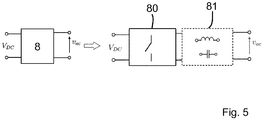
- the converter cells 13, 23 shown can have an internal structure 8 which is composed, for example, of power electronics components of any kind, for example transistors.
- the inner structure 8 can also be realized by a combination of a converter cell 80 according to the structure explained above with a downstream resonant tank 81. This further improves the switching ratio.
- the resonant tank 81 can have a circuit arrangement composed of inductors and capacitors.
Landscapes
- Engineering & Computer Science (AREA)
- Power Engineering (AREA)
- Dc-Dc Converters (AREA)
Claims (17)
- Convertisseur de tension (1) pour convertir une première tension continue (11), appliquée à un côté primaire (10) du convertisseur de tension (1), en une seconde tension continue (21), appliquée à un côté secondaire (20) du convertisseur de tension (1), le convertisseur de tension (1) étant conçu de manière modulaire avec une pluralité de modules convertisseurs (2) qui sont interconnectés entre eux sur le côté primaire (10), d'une part, et qui sont interconnectés entre eux sur le côté secondaire (20), d'autre part,dans lequel les modules convertisseurs (2) sont réalisés chacun sous la forme d'un pont actif multiple, d'une topologie de pleine résonance, d'une topologie de source de courant ou d'une topologie de source d'impédance, ayant un transformateur respectif (5) connecté entre le côté primaire (12) et le côté secondaire (22) d'un module convertisseur (2), les transformateurs (5) des modules convertisseurs (2) étant couplés magnétiquement les uns aux autres,caractérisé en ce que le couplage magnétique entre les modules convertisseurs (2) est formé par un noyau magnétique (6, 7) reliant magnétiquement leurs transformateurs (5),le noyau magnétique (7) est construit de manière modulaire à partir de modules de noyau individuels qui peuvent être enlevés et/ou remplacés respectivement séparément pour chaque module convertisseur (2), oules modules convertisseurs individuels (2) sont réalisés chacun avec des propres transformateurs (5), les transformateurs (5) magnétiquement couplés entre eux étant couplés entre eux de façon mécaniquement détachable, de manière à pouvoir remplacer un transformateur individuel (5) ou un enroulement de transformateur individuel (14, 24).
- Convertisseur de tension selon la revendication précédente,
caractérisé en ce que le noyau magnétique (6, 7) est réalisé sous forme de noyau magnétique annulairement fermé ou au moins sensiblement fermé. - Convertisseur de tension selon l'une des revendications 1 à 2,
caractérisé en ce que les transformateurs (5) sont formés par une pluralité d'enroulements de transformateur (14, 24) côté primaire et côté secondaire, disposés sur le noyau magnétique commun (7). - Convertisseur de tension selon l'une des revendications précédentes,
caractérisé en ce qu'un, plusieurs ou tous les modules convertisseurs (2) sont eux-mêmes, à leur tour, de construction modulaire, du fait qu'un tel module convertisseur (2) comprend une cellule de convertisseur (13) côté primaire, qui est connectée à une spire de transformateur (14) côté primaire du transformateur (5) du module convertisseur (2), et une cellule de convertisseur (23) côté secondaire qui est connectée à une spire de transformateur (24) côté secondaire du transformateur (5) du module convertisseur (2). - Convertisseur de tension selon la revendication précédente,
caractérisé en ce que, optionnellement, la cellule de convertisseur (13) côté primaire et/ou la cellule de convertisseur (23) côté secondaire peut être enlevée et/ou remplacée, de sorte qu'une ou plusieurs cellules de convertisseur côté primaire et/ou côté secondaire du convertisseur de tension peuvent être enlevées et/ou remplacées. - Convertisseur de tension selon l'une des revendications précédentes,
caractérisé en ce que les modules convertisseurs (2) sont reliés entre eux en série ou en parallèle sur leur côté primaire (12), et/ou les modules convertisseurs (2) sont reliés entre eux en série ou en parallèle sur leur côté secondaire (22). - Convertisseur de tension selon l'une des revendications précédentes,
caractérisé en ce que le convertisseur de tension (1) comprend un dispositif de commande (3) qui est conçu pour commander ou réguler le transfert de puissance électrique d'un module convertisseur (2) du convertisseur de tension (1) à un autre module convertisseur (2) du convertisseur de tension (1) ou à plusieurs autres modules convertisseurs (2) du convertisseur de tension (1), selon une valeur prédéfinie. - Convertisseur de tension selon la revendication précédente,
caractérisé en ce que le dispositif de commande (3) est conçu de telle sorte que, dans le cas d'un défaut d'un module convertisseur (2), survenant pendant le fonctionnement du convertisseur de tension (1), ledit module convertisseur (2) est complètement ou partiellement désactivé pendant le fonctionnement en cours du convertisseur de tension (1). - Convertisseur de tension selon la revendication précédente,
caractérisé en ce que le dispositif de commande (3) est conçu pour désactiver un module convertisseur (2) à désactiver uniquement sur le côté défectueux du module convertisseur (2), c'est-à-dire sur le côté primaire (12) ou sur le côté secondaire (22), et pour continuer à faire fonctionner l'autre côté respectif. - Convertisseur de tension selon l'une des revendications 6 à 8,
caractérisé en ce que le dispositif de commande (3) est conçu pour activer un module convertisseur (2), présent en tant que réserve, ou une cellule de convertisseur (13, 23), en cas de besoin en puissance croissant du convertisseur de tension (1) et/ou en cas de désactivation d'un module convertisseur (2) ou d'une partie de celui-ci, et pour l'intégrer au fonctionnement du convertisseur de tension (1). - Procédé de fonctionnement d'un convertisseur de tension (1) selon l'une des revendications précédentes,dans lequel le dispositif de commande (3) exécute une ou plusieurs étapes de procédé pour commander ou réguler la transmission de puissance électrique d'un module convertisseur (2) du convertisseur de tension (1) à un autre module convertisseur (2) du convertisseur de tension (1) ou à plusieurs autres modules convertisseurs (2) du convertisseur de tension (1), selon une valeur prédéfinie du convertisseur de tension (1),caractérisé en ce qu'un module convertisseur (2) à désactiver est désactivé uniquement sur un côté défectueux du module convertisseur (2), c'est-à-dire sur le côté primaire (12) ou sur le côté secondaire (22), et on continue à faire fonctionner l'autre côté respectif.
- Procédé selon la revendication 11,
caractérisé en ce qu'après détection d'un défaut d'un module convertisseur, que ce soit sur le côté primaire ou sur le côté secondaire, on continue à faire fonctionner le convertisseur de tension. - Procédé selon la revendication 12,
caractérisé en ce que, en cas de défaut d'un module convertisseur (2), survenant pendant le fonctionnement du convertisseur de tension (1), ledit module convertisseur (2) est complètement ou partiellement désactivé pendant le fonctionnement en cours du convertisseur de tension (1), et on continue à faire fonctionner le convertisseur de tension (1), le cas échéant après reconfiguration. - Procédé selon l'une des revendications 11 à 13,
caractérisé en ce qu'en cas de besoin en puissance croissant du convertisseur de tension (1) et/ou en cas de désactivation d'un module convertisseur (2) ou d'une partie de celui-ci, un module convertisseur (2), présent en tant que réserve, ou une cellule de convertisseur (13, 23) est activé(e) et intégré(e) au fonctionnement du convertisseur de tension (1). - Procédé selon l'une des revendications 11 à 14,
caractérisé en ce que le transfert de puissance électrique entre les modules convertisseurs ou les cellules de convertisseur du convertisseur de tension est effectué selon une valeur prédéfinie de vieillissement par laquelle leur vieillissement est influencé de manière prédéterminée par la régulation de la charge sur les composants individuels. - Procédé selon l'une des revendications 11 à 15,
caractérisé en ce que, après détection d'un défaut du convertisseur de tension, on effectue une reconfiguration d'au moins une partie du convertisseur de tension, par exemple d'une ou de plusieurs cellules de convertisseur, et on continue à faire fonctionner le convertisseur de tension avec la configuration modifiée. - Programme informatique ayant des moyens de code de programme, conçu pour mettre en oeuvre le procédé selon l'une des revendications 11 à 16, lorsque le programme informatique est exécuté sur un ordinateur du dispositif de commande (3).
Applications Claiming Priority (2)
| Application Number | Priority Date | Filing Date | Title |
|---|---|---|---|
| DE102017104138.9A DE102017104138A1 (de) | 2017-02-28 | 2017-02-28 | Spannungswandler, Verfahren zu dessen Betrieb und Computerprogramm |
| PCT/EP2018/054893 WO2018158294A1 (fr) | 2017-02-28 | 2018-02-28 | Transformateur de tension, procédé de fonctionnement de celui-ci et programme informatique |
Publications (2)
| Publication Number | Publication Date |
|---|---|
| EP3590183A1 EP3590183A1 (fr) | 2020-01-08 |
| EP3590183B1 true EP3590183B1 (fr) | 2021-09-01 |
Family
ID=61557272
Family Applications (1)
| Application Number | Title | Priority Date | Filing Date |
|---|---|---|---|
| EP18708394.4A Active EP3590183B1 (fr) | 2017-02-28 | 2018-02-28 | Transformateur de tension, procédé de fonctionnement de celui-ci et programme informatique |
Country Status (3)
| Country | Link |
|---|---|
| EP (1) | EP3590183B1 (fr) |
| DE (1) | DE102017104138A1 (fr) |
| WO (1) | WO2018158294A1 (fr) |
Families Citing this family (3)
| Publication number | Priority date | Publication date | Assignee | Title |
|---|---|---|---|---|
| DE102020205078A1 (de) * | 2020-04-22 | 2021-10-28 | Robert Bosch Gesellschaft mit beschränkter Haftung | Wandlervorrichtung für eine Leistungselektronik, elektrisches System mit einer Wandlervorrichtung und Verfahren zum Betreiben einer Wandlervorrichtung |
| CN113629985B (zh) * | 2021-07-16 | 2023-04-07 | 燕山大学 | 一种chb-qab拓扑结构的子模块电容优化控制方法 |
| CN115425858B (zh) * | 2022-09-30 | 2026-03-17 | 阳光电源股份有限公司 | 一种单级式多路直流接入变换器及其控制方法 |
Family Cites Families (9)
| Publication number | Priority date | Publication date | Assignee | Title |
|---|---|---|---|---|
| US5027264A (en) | 1989-09-29 | 1991-06-25 | Wisconsin Alumni Research Foundation | Power conversion apparatus for DC/DC conversion using dual active bridges |
| JP3361047B2 (ja) * | 1998-01-30 | 2003-01-07 | 株式会社東芝 | 車両用電源装置 |
| US7170764B2 (en) * | 2004-02-24 | 2007-01-30 | Vlt, Inc. | Adaptively configured voltage transformation module array |
| CA2723256A1 (fr) * | 2008-05-13 | 2009-11-19 | Abb Technology Ag | Noyau toroidal modulaire |
| US8227939B2 (en) * | 2009-06-11 | 2012-07-24 | Raytheon Company | Reconfigurable multi-cell power converter |
| US8930723B2 (en) * | 2009-10-07 | 2015-01-06 | Dell Products L.P. | System and method for multi-phase voltage regulation |
| US9165707B2 (en) * | 2011-09-30 | 2015-10-20 | Astec International Limited | Multiphase power converters having shared magnetic core sections |
| US8824179B2 (en) * | 2012-08-14 | 2014-09-02 | Rudolf Limpaecher | Soft-switching high voltage power converter |
| CN103595367B (zh) * | 2013-11-07 | 2017-03-08 | 华为技术有限公司 | 一种磁集成器件及一种功率转换电路 |
-
2017
- 2017-02-28 DE DE102017104138.9A patent/DE102017104138A1/de not_active Ceased
-
2018
- 2018-02-28 WO PCT/EP2018/054893 patent/WO2018158294A1/fr not_active Ceased
- 2018-02-28 EP EP18708394.4A patent/EP3590183B1/fr active Active
Also Published As
| Publication number | Publication date |
|---|---|
| EP3590183A1 (fr) | 2020-01-08 |
| WO2018158294A1 (fr) | 2018-09-07 |
| DE102017104138A1 (de) | 2018-08-30 |
Similar Documents
| Publication | Publication Date | Title |
|---|---|---|
| EP2389715B1 (fr) | Montage en série de régulateurs à découpage pour le transport d'énergie dans des systèmes de batterie | |
| DE102013212682B4 (de) | Energiespeichereinrichtung mit Gleichspannungsversorgungsschaltung und Verfahren zum Bereitstellen einer Gleichspannung aus einer Energiespeichereinrichtung | |
| EP3562701A1 (fr) | Découplage basse tension composé d'un système modulaire accumulateur d'énergie-onduleur | |
| DE102009027835A1 (de) | Hybrides Batteriesystem | |
| DE102012202860A1 (de) | Austauschbare Energiespeichereinrichtung und Verfahren zum Austauschen einer Energiespeichereinrichtung | |
| EP2553799A2 (fr) | Convertisseur direct sans transformateur | |
| EP3590183B1 (fr) | Transformateur de tension, procédé de fonctionnement de celui-ci et programme informatique | |
| DE102019211968A1 (de) | Ansteuerverfahren für einen Gleichspannungswandler und Gleichspannungswandler | |
| DE102014100256B4 (de) | Modularer Stromrichter | |
| WO2011057849A1 (fr) | Système de transmission d'énergie pour un système d'accumulation d'énergie | |
| EP4029137A1 (fr) | Convertisseur de tension | |
| EP2826126B1 (fr) | Dispositif électronique de puissance comportant une symétrisation d'un n ud de tension dans le circuit intermédiaire | |
| DE102012202856A1 (de) | Ladeschaltung für eine Energiespeichereinrichtung und Verfahren zum Laden einer Energiespeichereinrichtung | |
| DE102013212692A1 (de) | Energiespeichereinrichtung mit Gleichspannungsversorgungsschaltung | |
| DE102012206801A1 (de) | Schaltung mit einer stromrichterschaltung und verfahren zur leistungsanpassung | |
| DE102021108246A1 (de) | Ladestation und Verfahren zum Betreiben einer Ladestation | |
| EP4595179A1 (fr) | Dispositif convertisseur cc-cc, système d'alimentation électrique et procédé de décharge d'un condensateur de liaison cc | |
| WO2019020254A1 (fr) | Convertisseur continu-continu en pont complet | |
| EP4010973A1 (fr) | Convertisseur de tension continue et procédé de fonctionnement d'un convertisseur de tension continue | |
| WO2021037537A1 (fr) | Procédé de commande d'un convertisseur continu-continu et convertisseur continu-continu | |
| EP2566026A1 (fr) | Régulateur de tension continue | |
| DE202010007787U1 (de) | Gleichspannungssteller | |
| WO2026022306A1 (fr) | Dispositif convertisseur | |
| WO2025119585A1 (fr) | Système convertisseur de tension et son procédé de fonctionnement | |
| EP4635063A1 (fr) | Convertisseur de puissance et procédé de commande d'un convertisseur de puissance |
Legal Events
| Date | Code | Title | Description |
|---|---|---|---|
| STAA | Information on the status of an ep patent application or granted ep patent |
Free format text: STATUS: UNKNOWN |
|
| STAA | Information on the status of an ep patent application or granted ep patent |
Free format text: STATUS: THE INTERNATIONAL PUBLICATION HAS BEEN MADE |
|
| PUAI | Public reference made under article 153(3) epc to a published international application that has entered the european phase |
Free format text: ORIGINAL CODE: 0009012 |
|
| STAA | Information on the status of an ep patent application or granted ep patent |
Free format text: STATUS: REQUEST FOR EXAMINATION WAS MADE |
|
| 17P | Request for examination filed |
Effective date: 20190822 |
|
| AK | Designated contracting states |
Kind code of ref document: A1 Designated state(s): AL AT BE BG CH CY CZ DE DK EE ES FI FR GB GR HR HU IE IS IT LI LT LU LV MC MK MT NL NO PL PT RO RS SE SI SK SM TR |
|
| AX | Request for extension of the european patent |
Extension state: BA ME |
|
| RIN1 | Information on inventor provided before grant (corrected) |
Inventor name: ANDRESEN, MARKUS Inventor name: COSTA, LEVY Inventor name: LISERRE, MARCO Inventor name: BUTICCHI, GIAMPAOLO |
|
| DAV | Request for validation of the european patent (deleted) | ||
| DAX | Request for extension of the european patent (deleted) | ||
| GRAP | Despatch of communication of intention to grant a patent |
Free format text: ORIGINAL CODE: EPIDOSNIGR1 |
|
| STAA | Information on the status of an ep patent application or granted ep patent |
Free format text: STATUS: GRANT OF PATENT IS INTENDED |
|
| INTG | Intention to grant announced |
Effective date: 20210504 |
|
| GRAS | Grant fee paid |
Free format text: ORIGINAL CODE: EPIDOSNIGR3 |
|
| GRAA | (expected) grant |
Free format text: ORIGINAL CODE: 0009210 |
|
| STAA | Information on the status of an ep patent application or granted ep patent |
Free format text: STATUS: THE PATENT HAS BEEN GRANTED |
|
| AK | Designated contracting states |
Kind code of ref document: B1 Designated state(s): AL AT BE BG CH CY CZ DE DK EE ES FI FR GB GR HR HU IE IS IT LI LT LU LV MC MK MT NL NO PL PT RO RS SE SI SK SM TR |
|
| REG | Reference to a national code |
Ref country code: GB Ref legal event code: FG4D Free format text: NOT ENGLISH |
|
| REG | Reference to a national code |
Ref country code: CH Ref legal event code: EP Ref country code: AT Ref legal event code: REF Ref document number: 1427276 Country of ref document: AT Kind code of ref document: T Effective date: 20210915 |
|
| REG | Reference to a national code |
Ref country code: DE Ref legal event code: R096 Ref document number: 502018006831 Country of ref document: DE |
|
| REG | Reference to a national code |
Ref country code: IE Ref legal event code: FG4D Free format text: LANGUAGE OF EP DOCUMENT: GERMAN |
|
| REG | Reference to a national code |
Ref country code: LT Ref legal event code: MG9D |
|
| REG | Reference to a national code |
Ref country code: NL Ref legal event code: MP Effective date: 20210901 |
|
| PG25 | Lapsed in a contracting state [announced via postgrant information from national office to epo] |
Ref country code: NO Free format text: LAPSE BECAUSE OF FAILURE TO SUBMIT A TRANSLATION OF THE DESCRIPTION OR TO PAY THE FEE WITHIN THE PRESCRIBED TIME-LIMIT Effective date: 20211201 Ref country code: BG Free format text: LAPSE BECAUSE OF FAILURE TO SUBMIT A TRANSLATION OF THE DESCRIPTION OR TO PAY THE FEE WITHIN THE PRESCRIBED TIME-LIMIT Effective date: 20211201 Ref country code: LT Free format text: LAPSE BECAUSE OF FAILURE TO SUBMIT A TRANSLATION OF THE DESCRIPTION OR TO PAY THE FEE WITHIN THE PRESCRIBED TIME-LIMIT Effective date: 20210901 Ref country code: RS Free format text: LAPSE BECAUSE OF FAILURE TO SUBMIT A TRANSLATION OF THE DESCRIPTION OR TO PAY THE FEE WITHIN THE PRESCRIBED TIME-LIMIT Effective date: 20210901 Ref country code: SE Free format text: LAPSE BECAUSE OF FAILURE TO SUBMIT A TRANSLATION OF THE DESCRIPTION OR TO PAY THE FEE WITHIN THE PRESCRIBED TIME-LIMIT Effective date: 20210901 Ref country code: ES Free format text: LAPSE BECAUSE OF FAILURE TO SUBMIT A TRANSLATION OF THE DESCRIPTION OR TO PAY THE FEE WITHIN THE PRESCRIBED TIME-LIMIT Effective date: 20210901 Ref country code: FI Free format text: LAPSE BECAUSE OF FAILURE TO SUBMIT A TRANSLATION OF THE DESCRIPTION OR TO PAY THE FEE WITHIN THE PRESCRIBED TIME-LIMIT Effective date: 20210901 Ref country code: HR Free format text: LAPSE BECAUSE OF FAILURE TO SUBMIT A TRANSLATION OF THE DESCRIPTION OR TO PAY THE FEE WITHIN THE PRESCRIBED TIME-LIMIT Effective date: 20210901 |
|
| PG25 | Lapsed in a contracting state [announced via postgrant information from national office to epo] |
Ref country code: PL Free format text: LAPSE BECAUSE OF FAILURE TO SUBMIT A TRANSLATION OF THE DESCRIPTION OR TO PAY THE FEE WITHIN THE PRESCRIBED TIME-LIMIT Effective date: 20210901 Ref country code: LV Free format text: LAPSE BECAUSE OF FAILURE TO SUBMIT A TRANSLATION OF THE DESCRIPTION OR TO PAY THE FEE WITHIN THE PRESCRIBED TIME-LIMIT Effective date: 20210901 Ref country code: GR Free format text: LAPSE BECAUSE OF FAILURE TO SUBMIT A TRANSLATION OF THE DESCRIPTION OR TO PAY THE FEE WITHIN THE PRESCRIBED TIME-LIMIT Effective date: 20211202 |
|
| PG25 | Lapsed in a contracting state [announced via postgrant information from national office to epo] |
Ref country code: IS Free format text: LAPSE BECAUSE OF FAILURE TO SUBMIT A TRANSLATION OF THE DESCRIPTION OR TO PAY THE FEE WITHIN THE PRESCRIBED TIME-LIMIT Effective date: 20220101 Ref country code: SM Free format text: LAPSE BECAUSE OF FAILURE TO SUBMIT A TRANSLATION OF THE DESCRIPTION OR TO PAY THE FEE WITHIN THE PRESCRIBED TIME-LIMIT Effective date: 20210901 Ref country code: SK Free format text: LAPSE BECAUSE OF FAILURE TO SUBMIT A TRANSLATION OF THE DESCRIPTION OR TO PAY THE FEE WITHIN THE PRESCRIBED TIME-LIMIT Effective date: 20210901 Ref country code: RO Free format text: LAPSE BECAUSE OF FAILURE TO SUBMIT A TRANSLATION OF THE DESCRIPTION OR TO PAY THE FEE WITHIN THE PRESCRIBED TIME-LIMIT Effective date: 20210901 Ref country code: PT Free format text: LAPSE BECAUSE OF FAILURE TO SUBMIT A TRANSLATION OF THE DESCRIPTION OR TO PAY THE FEE WITHIN THE PRESCRIBED TIME-LIMIT Effective date: 20220103 Ref country code: NL Free format text: LAPSE BECAUSE OF FAILURE TO SUBMIT A TRANSLATION OF THE DESCRIPTION OR TO PAY THE FEE WITHIN THE PRESCRIBED TIME-LIMIT Effective date: 20210901 Ref country code: EE Free format text: LAPSE BECAUSE OF FAILURE TO SUBMIT A TRANSLATION OF THE DESCRIPTION OR TO PAY THE FEE WITHIN THE PRESCRIBED TIME-LIMIT Effective date: 20210901 Ref country code: CZ Free format text: LAPSE BECAUSE OF FAILURE TO SUBMIT A TRANSLATION OF THE DESCRIPTION OR TO PAY THE FEE WITHIN THE PRESCRIBED TIME-LIMIT Effective date: 20210901 Ref country code: AL Free format text: LAPSE BECAUSE OF FAILURE TO SUBMIT A TRANSLATION OF THE DESCRIPTION OR TO PAY THE FEE WITHIN THE PRESCRIBED TIME-LIMIT Effective date: 20210901 |
|
| REG | Reference to a national code |
Ref country code: DE Ref legal event code: R097 Ref document number: 502018006831 Country of ref document: DE |
|
| PLBE | No opposition filed within time limit |
Free format text: ORIGINAL CODE: 0009261 |
|
| STAA | Information on the status of an ep patent application or granted ep patent |
Free format text: STATUS: NO OPPOSITION FILED WITHIN TIME LIMIT |
|
| PG25 | Lapsed in a contracting state [announced via postgrant information from national office to epo] |
Ref country code: IT Free format text: LAPSE BECAUSE OF FAILURE TO SUBMIT A TRANSLATION OF THE DESCRIPTION OR TO PAY THE FEE WITHIN THE PRESCRIBED TIME-LIMIT Effective date: 20210901 Ref country code: DK Free format text: LAPSE BECAUSE OF FAILURE TO SUBMIT A TRANSLATION OF THE DESCRIPTION OR TO PAY THE FEE WITHIN THE PRESCRIBED TIME-LIMIT Effective date: 20210901 |
|
| 26N | No opposition filed |
Effective date: 20220602 |
|
| PG25 | Lapsed in a contracting state [announced via postgrant information from national office to epo] |
Ref country code: SI Free format text: LAPSE BECAUSE OF FAILURE TO SUBMIT A TRANSLATION OF THE DESCRIPTION OR TO PAY THE FEE WITHIN THE PRESCRIBED TIME-LIMIT Effective date: 20210901 |
|
| PG25 | Lapsed in a contracting state [announced via postgrant information from national office to epo] |
Ref country code: MC Free format text: LAPSE BECAUSE OF FAILURE TO SUBMIT A TRANSLATION OF THE DESCRIPTION OR TO PAY THE FEE WITHIN THE PRESCRIBED TIME-LIMIT Effective date: 20210901 |
|
| REG | Reference to a national code |
Ref country code: CH Ref legal event code: PL |
|
| REG | Reference to a national code |
Ref country code: BE Ref legal event code: MM Effective date: 20220228 |
|
| PG25 | Lapsed in a contracting state [announced via postgrant information from national office to epo] |
Ref country code: LU Free format text: LAPSE BECAUSE OF NON-PAYMENT OF DUE FEES Effective date: 20220228 |
|
| PG25 | Lapsed in a contracting state [announced via postgrant information from national office to epo] |
Ref country code: LI Free format text: LAPSE BECAUSE OF NON-PAYMENT OF DUE FEES Effective date: 20220228 Ref country code: IE Free format text: LAPSE BECAUSE OF NON-PAYMENT OF DUE FEES Effective date: 20220228 Ref country code: CH Free format text: LAPSE BECAUSE OF NON-PAYMENT OF DUE FEES Effective date: 20220228 |
|
| PG25 | Lapsed in a contracting state [announced via postgrant information from national office to epo] |
Ref country code: BE Free format text: LAPSE BECAUSE OF NON-PAYMENT OF DUE FEES Effective date: 20220228 |
|
| REG | Reference to a national code |
Ref country code: DE Ref legal event code: R082 Ref document number: 502018006831 Country of ref document: DE Representative=s name: MEISSNER BOLTE PATENTANWAELTE RECHTSANWAELTE P, DE |
|
| REG | Reference to a national code |
Ref country code: AT Ref legal event code: MM01 Ref document number: 1427276 Country of ref document: AT Kind code of ref document: T Effective date: 20230228 |
|
| PG25 | Lapsed in a contracting state [announced via postgrant information from national office to epo] |
Ref country code: AT Free format text: LAPSE BECAUSE OF NON-PAYMENT OF DUE FEES Effective date: 20230228 |
|
| PG25 | Lapsed in a contracting state [announced via postgrant information from national office to epo] |
Ref country code: MK Free format text: LAPSE BECAUSE OF FAILURE TO SUBMIT A TRANSLATION OF THE DESCRIPTION OR TO PAY THE FEE WITHIN THE PRESCRIBED TIME-LIMIT Effective date: 20210901 Ref country code: CY Free format text: LAPSE BECAUSE OF FAILURE TO SUBMIT A TRANSLATION OF THE DESCRIPTION OR TO PAY THE FEE WITHIN THE PRESCRIBED TIME-LIMIT Effective date: 20210901 Ref country code: AT Free format text: LAPSE BECAUSE OF NON-PAYMENT OF DUE FEES Effective date: 20230228 |
|
| PG25 | Lapsed in a contracting state [announced via postgrant information from national office to epo] |
Ref country code: HU Free format text: LAPSE BECAUSE OF FAILURE TO SUBMIT A TRANSLATION OF THE DESCRIPTION OR TO PAY THE FEE WITHIN THE PRESCRIBED TIME-LIMIT; INVALID AB INITIO Effective date: 20180228 |
|
| PG25 | Lapsed in a contracting state [announced via postgrant information from national office to epo] |
Ref country code: TR Free format text: LAPSE BECAUSE OF FAILURE TO SUBMIT A TRANSLATION OF THE DESCRIPTION OR TO PAY THE FEE WITHIN THE PRESCRIBED TIME-LIMIT Effective date: 20210901 |
|
| PG25 | Lapsed in a contracting state [announced via postgrant information from national office to epo] |
Ref country code: MT Free format text: LAPSE BECAUSE OF FAILURE TO SUBMIT A TRANSLATION OF THE DESCRIPTION OR TO PAY THE FEE WITHIN THE PRESCRIBED TIME-LIMIT Effective date: 20210901 |
|
| PGFP | Annual fee paid to national office [announced via postgrant information from national office to epo] |
Ref country code: GB Payment date: 20260120 Year of fee payment: 9 |
|
| PGFP | Annual fee paid to national office [announced via postgrant information from national office to epo] |
Ref country code: DE Payment date: 20260128 Year of fee payment: 9 |
|
| PGFP | Annual fee paid to national office [announced via postgrant information from national office to epo] |
Ref country code: AT Payment date: 20260410 Year of fee payment: 5 |
|
| PGFP | Annual fee paid to national office [announced via postgrant information from national office to epo] |
Ref country code: FR Payment date: 20260120 Year of fee payment: 9 |