EP3590636B1 - Oberflächenbeschichtetes schneidwerkzeug und herstellungsverfahren dafür - Google Patents
Oberflächenbeschichtetes schneidwerkzeug und herstellungsverfahren dafür Download PDFInfo
- Publication number
- EP3590636B1 EP3590636B1 EP17898614.7A EP17898614A EP3590636B1 EP 3590636 B1 EP3590636 B1 EP 3590636B1 EP 17898614 A EP17898614 A EP 17898614A EP 3590636 B1 EP3590636 B1 EP 3590636B1
- Authority
- EP
- European Patent Office
- Prior art keywords
- unit phase
- layer
- rich layer
- less
- coating
- Prior art date
- Legal status (The legal status is an assumption and is not a legal conclusion. Google has not performed a legal analysis and makes no representation as to the accuracy of the status listed.)
- Active
Links
Images
Classifications
-
- B—PERFORMING OPERATIONS; TRANSPORTING
- B23—MACHINE TOOLS; METAL-WORKING NOT OTHERWISE PROVIDED FOR
- B23B—TURNING; BORING
- B23B27/00—Tools for turning or boring machines; Tools of a similar kind in general; Accessories therefor
- B23B27/14—Cutting tools of which the bits or tips or cutting inserts are of special material
- B23B27/148—Composition of the cutting inserts
-
- B—PERFORMING OPERATIONS; TRANSPORTING
- B23—MACHINE TOOLS; METAL-WORKING NOT OTHERWISE PROVIDED FOR
- B23B—TURNING; BORING
- B23B27/00—Tools for turning or boring machines; Tools of a similar kind in general; Accessories therefor
- B23B27/14—Cutting tools of which the bits or tips or cutting inserts are of special material
-
- B—PERFORMING OPERATIONS; TRANSPORTING
- B23—MACHINE TOOLS; METAL-WORKING NOT OTHERWISE PROVIDED FOR
- B23B—TURNING; BORING
- B23B51/00—Tools for drilling machines
-
- B—PERFORMING OPERATIONS; TRANSPORTING
- B23—MACHINE TOOLS; METAL-WORKING NOT OTHERWISE PROVIDED FOR
- B23C—MILLING
- B23C5/00—Milling-cutters
- B23C5/16—Milling-cutters characterised by physical features other than shape
-
- B—PERFORMING OPERATIONS; TRANSPORTING
- B23—MACHINE TOOLS; METAL-WORKING NOT OTHERWISE PROVIDED FOR
- B23D—PLANING; SLOTTING; SHEARING; BROACHING; SAWING; FILING; SCRAPING; LIKE OPERATIONS FOR WORKING METAL BY REMOVING MATERIAL, NOT OTHERWISE PROVIDED FOR
- B23D77/00—Reaming tools
-
- B—PERFORMING OPERATIONS; TRANSPORTING
- B23—MACHINE TOOLS; METAL-WORKING NOT OTHERWISE PROVIDED FOR
- B23F—MAKING GEARS OR TOOTHED RACKS
- B23F21/00—Tools specially adapted for use in machines for manufacturing gear teeth
-
- B—PERFORMING OPERATIONS; TRANSPORTING
- B23—MACHINE TOOLS; METAL-WORKING NOT OTHERWISE PROVIDED FOR
- B23G—THREAD CUTTING; WORKING OF SCREWS, BOLT HEADS, OR NUTS, IN CONJUNCTION THEREWITH
- B23G5/00—Thread-cutting tools; Die-heads
- B23G5/02—Thread-cutting tools; Die-heads without means for adjustment
- B23G5/06—Taps
-
- C—CHEMISTRY; METALLURGY
- C23—COATING METALLIC MATERIAL; COATING MATERIAL WITH METALLIC MATERIAL; CHEMICAL SURFACE TREATMENT; DIFFUSION TREATMENT OF METALLIC MATERIAL; COATING BY VACUUM EVAPORATION, BY SPUTTERING, BY ION IMPLANTATION OR BY CHEMICAL VAPOUR DEPOSITION, IN GENERAL; INHIBITING CORROSION OF METALLIC MATERIAL OR INCRUSTATION IN GENERAL
- C23C—COATING METALLIC MATERIAL; COATING MATERIAL WITH METALLIC MATERIAL; SURFACE TREATMENT OF METALLIC MATERIAL BY DIFFUSION INTO THE SURFACE, BY CHEMICAL CONVERSION OR SUBSTITUTION; COATING BY VACUUM EVAPORATION, BY SPUTTERING, BY ION IMPLANTATION OR BY CHEMICAL VAPOUR DEPOSITION, IN GENERAL
- C23C16/00—Chemical coating by decomposition of gaseous compounds, without leaving reaction products of surface material in the coating, i.e. chemical vapour deposition [CVD] processes
- C23C16/22—Chemical coating by decomposition of gaseous compounds, without leaving reaction products of surface material in the coating, i.e. chemical vapour deposition [CVD] processes characterised by the deposition of inorganic material, other than metallic material
- C23C16/30—Deposition of compounds, mixtures or solid solutions, e.g. borides, carbides, nitrides
- C23C16/34—Nitrides
-
- C—CHEMISTRY; METALLURGY
- C23—COATING METALLIC MATERIAL; COATING MATERIAL WITH METALLIC MATERIAL; CHEMICAL SURFACE TREATMENT; DIFFUSION TREATMENT OF METALLIC MATERIAL; COATING BY VACUUM EVAPORATION, BY SPUTTERING, BY ION IMPLANTATION OR BY CHEMICAL VAPOUR DEPOSITION, IN GENERAL; INHIBITING CORROSION OF METALLIC MATERIAL OR INCRUSTATION IN GENERAL
- C23C—COATING METALLIC MATERIAL; COATING MATERIAL WITH METALLIC MATERIAL; SURFACE TREATMENT OF METALLIC MATERIAL BY DIFFUSION INTO THE SURFACE, BY CHEMICAL CONVERSION OR SUBSTITUTION; COATING BY VACUUM EVAPORATION, BY SPUTTERING, BY ION IMPLANTATION OR BY CHEMICAL VAPOUR DEPOSITION, IN GENERAL
- C23C16/00—Chemical coating by decomposition of gaseous compounds, without leaving reaction products of surface material in the coating, i.e. chemical vapour deposition [CVD] processes
- C23C16/22—Chemical coating by decomposition of gaseous compounds, without leaving reaction products of surface material in the coating, i.e. chemical vapour deposition [CVD] processes characterised by the deposition of inorganic material, other than metallic material
- C23C16/30—Deposition of compounds, mixtures or solid solutions, e.g. borides, carbides, nitrides
- C23C16/36—Carbonitrides
-
- C—CHEMISTRY; METALLURGY
- C23—COATING METALLIC MATERIAL; COATING MATERIAL WITH METALLIC MATERIAL; CHEMICAL SURFACE TREATMENT; DIFFUSION TREATMENT OF METALLIC MATERIAL; COATING BY VACUUM EVAPORATION, BY SPUTTERING, BY ION IMPLANTATION OR BY CHEMICAL VAPOUR DEPOSITION, IN GENERAL; INHIBITING CORROSION OF METALLIC MATERIAL OR INCRUSTATION IN GENERAL
- C23C—COATING METALLIC MATERIAL; COATING MATERIAL WITH METALLIC MATERIAL; SURFACE TREATMENT OF METALLIC MATERIAL BY DIFFUSION INTO THE SURFACE, BY CHEMICAL CONVERSION OR SUBSTITUTION; COATING BY VACUUM EVAPORATION, BY SPUTTERING, BY ION IMPLANTATION OR BY CHEMICAL VAPOUR DEPOSITION, IN GENERAL
- C23C16/00—Chemical coating by decomposition of gaseous compounds, without leaving reaction products of surface material in the coating, i.e. chemical vapour deposition [CVD] processes
- C23C16/56—After-treatment
-
- B—PERFORMING OPERATIONS; TRANSPORTING
- B23—MACHINE TOOLS; METAL-WORKING NOT OTHERWISE PROVIDED FOR
- B23B—TURNING; BORING
- B23B2226/00—Materials of tools or workpieces not comprising a metal
- B23B2226/12—Boron nitride
-
- B—PERFORMING OPERATIONS; TRANSPORTING
- B23—MACHINE TOOLS; METAL-WORKING NOT OTHERWISE PROVIDED FOR
- B23B—TURNING; BORING
- B23B2228/00—Properties of materials of tools or workpieces, materials of tools or workpieces applied in a specific manner
- B23B2228/10—Coatings
Definitions
- the present invention relates to a surface-coated cutting tool and a method for manufacturing the same.
- the present application claims priority based on Japanese Patent Application No. 2017-037375 filed on February 28, 2017 .
- Patent Literature 1 discloses as a surface coated member a member having a Ti 1-x Al x N coating.
- This Ti 1-x Al x N coating has a stoichiometric coefficient of 0.75 ⁇ x ⁇ 0.93, and has a lattice constant a of 0.412-0.405 nm and a single-phase cubic NaCl structure.
- the Ti 1-x Al x N coating is formed through CVD (Chemical Vapor Deposition).
- a first gaseous mixture composed of AlCl 3 , TiCl 4 , H 2 and Ar, and a second gaseous mixture composed of NH 3 and N 2 are introduced into a hot wall type CVD reactor with a substrate accommodated therein to grow a crystal of Ti 1-x Al x N.
- the coating formed by this method has a higher content ratio of Al than a Ti 1-x Al x N coating produced in a known PVD method. For this reason, it is supposed that a surface coated member having the coating has high oxidation resistance and high hardness, and can exhibit excellent abrasion resistance at high temperature.
- Patent Literature 2 discloses a surface coated member.
- the surface coated member has a hard coating layer formed through CVD.
- the hard coating layer includes hard particles, and the hard particle includes a multilayer structure in which an AlTiN layer in a NaCl structure with a relatively high atomic ratio of Ti and an AlTiN layer in a NaCl structure with a relatively low atomic ratio of Ti are repeatedly stacked (a so-called lamellar phase).
- the lamellar phase has a layer stacking period of 0.5 to 20 nm.
- the hard coating layer has an indentation hardness equal to or greater than 3000 kgf(s)/mm 2 (29.4 GPa) and thus has high hardness, and the surface coated member of Patent Literature 2 can thus exhibit excellent abrasion resistance.
- EP3091102A1 relates to a hard coating, cutting tool, and a hard coating manufacturing method. J. TODT et al, Surface and Coatings Technology, (20160000), vol. 291, pages 89 - 93 , relates to a Al-rich cubic Al 0.8 Ti 0.2 N coating with self-organized nano-lamellar microstructure and its thermal and mechanical properties.
- the present invention provides a surface-coated cutting tool according to claim 1.
- the present invention also provides a method for manufacturing a surface-coated cutting tool according to claim 2.
- the Ti 1-x Al x N coating of the surface coated member disclosed in Patent Literature 1 has x larger than 0.7, it has a large strain caused in a crystal structure of Ti 1-x Al x N. Accordingly, when the coating receives energy, the Ti 1-x Al x N crystal makes phase transition to a more stable wurtzite type crystal structure. Accordingly, when the surface coated member is applied to a cutting tool and used in cutting, the heat caused in the cutting causes phase transition of the crystal structure of Ti 1-x Al x N, which tends to cause a crack in the coating and when the crack extends it leads to a sudden fracture.
- the surface coated member disclosed in Patent Literature 2 has room for improvement in terms of initial abrasion when it is used for a cutting tool. Although the cause is unknown, it is considered as follows: while the lamellar phase in the hard particle is excellent in deformation resistance in the layer stacking direction, it easily has dislocation in the longitudinal direction when an external load is received. The dislocation serves as a starting point to destruct the lamellar phase, which leads to destruction of the hard particle and hence develops initial abrasion. Thus a surface coated member which has high hardness and is also less likely to have initial abrasion has not been implemented, and there is a need for its development.
- a surface-coated cutting tool which has high hardness and is less likely to have initial abrasion can be provided.
- the present inventors in diligently creating a coating to suppress initial abrasion, have arrived at applying a heat treatment to the lamellar phase that is disclosed in Patent Literature 2 to diffuse metal atoms such as Al in the lamellar phase. While conventionally it has been believed that a coating having undergone a heat treatment is degraded in quality, the present inventors have found that by performing a special control in the heat treatment to stop spinodal decomposition before the crystal grains constituting the lamellar phase make phase transition to the wurtzite crystal structure, a specific phase which suppresses initial abrasion can be formed inside the crystal grain.
- a surface-coated cutting tool in one aspect of the present invention is a surface-coated cutting tool according to claim 1. Such a configuration allows the surface-coated cutting tool to have high hardness and also suppress initial abrasion.
- the hard particles occupy 50% by volume or more and 95% by volume or less of the Al-rich layer. This can provide further higher hardness and also further suppress initial abrasion.
- the first unit phase has a size of 2 nm or more and 15 nm or less in the ⁇ 100> orientation. This can provide still further higher hardness and also still further suppress initial abrasion.
- a method for manufacturing a surface-coated cutting tool in one aspect of the present invention is according to claim 2. Such a configuration allows a surface-coated cutting tool to be manufactured which has higher hardness and is also less likely to have initial abrasion.
- the first step includes a first operation of obtaining a mixture gas by mixing a first mixture gas and a second mixture gas at a temperature ranging from 650°C to 850°C with a pressure ranging from 2 kPa to 4 kPa applied and a second operation of ejecting the mixture gas toward a surface of the substrate at the temperature with the pressure applied to form the lamellar layer, and the first mixture gas includes AlCl 3 gas, TiCl 4 gas, and H 2 gas, and the second mixture gas includes NH 3 gas and Ar gas.
- This can provide a lamellar layer for forming an Al-rich layer which has further higher hardness and is further less likely to have initial abrasion.
- the lamellar layer includes a third unit phase and a fourth unit phase, the third unit phase and the fourth unit phase are stacked alternately, the third unit phase is composed of a nitride or carbonitride of Al s Ti 1-s , the third unit phase has an atomic ratio s of Al of 0.7 or more and 0.95 or less, the fourth unit phase is composed of a nitride or carbonitride of Al t Ti 1-t , and the fourth unit phase has an atomic ratio t of Al of 0.5 or more and less than 0.7.
- This can provide an Al-rich layer which has further higher hardness and is further less likely to have initial abrasion.
- an expression in the form of "A-B” means a range's upper and lower limits (that is, A or more and B or less), and when A is not accompanied by any unit and B is alone accompanied by a unit, A has the same unit as B.
- a compound or the like when a compound or the like is represented by a chemical formula without specifying any specific atomic ratio, it includes any conventionally known atomic ratio and is not necessarily limited to those falling within the stoichiometric range.
- metallic elements such as titanium (Ti), aluminum (Al), silicon (Si), tantalum (Ta), chromium (Cr) and the like, and a nonmetallic element such as nitrogen (N), oxygen (O), carbon (C), or the like do not necessarily have to configure a stoichiometric composition.
- a surface-coated cutting tool includes a substrate and a coating formed on a surface of the substrate.
- the coating preferably coats the entire surface of the substrate. However, even if the substrate is partially uncoated with the coating or the coating is partially different in configuration, such does not depart from the scope of the present invention.
- Such a surface coated cutting tool can be exemplified for example by drills, end mills, indexable cutting inserts for drills, indexable cutting inserts for end mills, indexable cutting inserts for milling, indexable cutting inserts for turning, metal saws, gear cutting tools, reamers, taps, and the like.
- the substrate can be any substrate conventionally known as a substrate of this type.
- a cemented carbide for example, a WC-base cemented carbide or a material containing WC and in addition, Co, or a carbonitride of Ti, Ta, Nb, or the like added
- a cermet mainly composed of TiC, TiN, TiCN, or the like
- a high-speed steel a ceramic material (titanium carbide, silicon carbide, silicon nitride, aluminum nitride, aluminum oxide, and the like), a cubic crystal boron nitride sintered material, and a diamond sintered material.
- a WC-based cemented carbide or a cermet a TiCN-base cermet, in particular. This is because these substrates are particularly excellent in balance between hardness and strength at high temperature and have excellent characteristics as a substrate of a surface coated cutting tool for the above-described applications.
- the substrate also includes a substrate with or without a chip breaker. Furthermore, when cutting a workpiece, a cutting edge has a ridge line portion serving as a center for cutting, which has a shape also including a sharp edge (a ridge formed by a rake face and a flank face), a honed edge (a sharp edge rounded), a negative land (with beveling applied), and a combination of honing and the negative land.
- the coating includes one or two or more layers. At least one of the layers is an Al-rich layer including hard particles. Preferably, the coating has a thickness of 3 to 30 ⁇ m. When the thickness is less than 3 ⁇ m, abrasion resistance tends to be insufficient. When the thickness exceeds 30 ⁇ m, the coating tends to peel off or break during intermittent working when a large stress is applied between the coating and the substrate.
- the coating may include another layer insofar as the coating includes at least one Al-rich layer.
- the other layer can for example be an Al 2 O 3 layer, a TiB 2 layer, a TiBN layer, an AlN layer (wurtzite type), a TiN layer, a TiCN layer, a TiBNO layer, a TiCNO layer, a TiAlN layer, a TiAlCN layer, a TiAlON layer, a TiAlONC layer, or the like.
- including a TiN layer, a TiC layer, a TiCN layer, or a TiBN layer as an underlying layer directly on the substrate can enhance adhesion between the substrate and the coating.
- the coating can be enhanced in oxidation resistance.
- including an outermost layer made of a TiN layer, a TiC layer, a TiCN layer, a TiBN layer or the like can provide identification of whether the surface-coated cutting tool has a used cutting edge.
- the other layer preferably has a thickness of 0.1 to 10 ⁇ m.
- the coating is composed of one or two or more layers with at least one thereof being an Al-rich layer including hard particles.
- the Al-rich layer has a thickness of 1 ⁇ m or more and 20 ⁇ m or less, preferably 3 ⁇ m or more to 15 ⁇ m or less.
- abrasion resistance tends to be insufficient.
- the Al rich layer has a thickness exceeding 20 ⁇ m, the Al rich layer tends to peel off or break during intermittent working when a large stress is applied between the Al rich layer and the substrate.
- Al-rich layer partially including a phase composed of other than hard particles, as will be described hereinafter, e.g., an amorphous phase or a wurtzite hard phase, does not depart from the scope of the present invention.
- Al-rich in the Al-rich layer means that the layer at any five portions has a metal composition with an Al content exceeding 0.5 on average.
- the Al-rich layer, the other layer, and the coating can be measured in thickness as follows: the surface-coated cutting tool is cut parallel to the direction normal to a surface of the substrate to obtain a cross-sectional sample which is in turn observed with a transmission electron microscope (TEM (trade name: "JEM-2100F” manufactured by JEOL Ltd.)). Furthermore, the Al-rich layer, the other layer, and the coating can be measured in thickness for example by obtaining five cross-sectional samples, measuring thickness at any three locations in each sample, and representing an average value thereof as the thickness.
- TEM transmission electron microscope
- a known method can be used to obtain a cross-sectional sample of the surface-coated cutting tool.
- the hard particle has a sodium chloride type crystal structure, and includes a first unit phase in the form of a plurality of lumps and a second unit phase interposed between the lumps of the first unit phase.
- the first unit phase is composed of a nitride or carbonitride of Al x Ti 1-x , and has an atomic ratio x of Al of 0.7 or more and 0.96 or less. Furthermore, when the nitride of Al x Ti 1-x is represented as Al x Ti 1-x N z1 , a relationship of 0.8 ⁇ z1 ⁇ 1.2 is satisfied. When the carbonitride of Al x Ti 1-x is represented as Al x Ti 1-x C m1 N n1 , a relationship of 0.8 ⁇ m1 + n1 ⁇ 1.2 is satisfied.
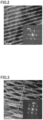
- Fig. 3 as a cross-sectional structure internal to the hard particle, there appears a form in which the second unit phase in the form of a thin line surrounds the first unit phase in the form of lumps. That is, the hard particle internally has a structure in which the second unit phase in the form of a thin line surrounds the first unit phase in the form of a plurality of lumps. Further, by observing the Fig. 3 TEM image, it can be seen that the hard particle has the first unit phase and the second unit phase both having a sodium chloride type crystal structure, as has been described above, with the first and second unit phases lattice-matched.
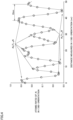
- Fig. 4 is a graph showing a result of a composition analysis in the direction indicated in Fig. 3 by the arrow (i.e., the ⁇ 100> orientation) by using an energy dispersive X-ray spectroscopy (EDX) apparatus (trade name: "JED-2300" manufactured by JEOL Ltd.) accompanying the above transmission electron microscope (TEM).
- EDX energy dispersive X-ray spectroscopy
- the Fig. 4 graph has a horizontal axis representing a distance measured in the direction indicated by the arrow (the ⁇ 100> orientation), and a vertical axis representing an atomic ratio of Al (Al/(Al + Ti)).
- Fig. 4 shows how the atomic ratio of Al changes along the ⁇ 100> orientation, that is, how the hard particle's internal composition changes along the ⁇ 100> orientation.
- the first unit phase includes a composition of a nitride or carbonitride of Al x Ti 1-x in which the atomic ratio of Al is 0.7 or more and maximized (or peaks).
- the atomic ratio of Al has peaks at 0.9, 0.79, 0.88, 0.8, 0.92.
- the first unit phase has an atomic ratio of Al gradually decreasing from these peaks toward the second unit phase adjacent to the first unit phase.
- the second unit phase includes a nitride or carbonitride of Al y Ti 1-y in which the atomic ratio of Al is less than 0.7 and minimized (or forms valleys).
- Fig. 4 the composition of a nitride or carbonitride of Al x Ti 1-x in which the atomic ratio of Al is 0.7 or more and maximized (or peaks).
- the atomic ratio of Al has peaks at 0.9, 0.79, 0.88, 0.8, 0.92.
- the first unit phase has an atomic ratio of Al gradually decreasing from these peaks toward the second unit
- the atomic ratio of Al has valleys of 0.55, 0.54, 0.58, 0.6, 0.52.
- the second unit phase has an atomic ratio of Al gradually increasing from these valleys toward the first unit phase adjacent to the second unit phase.
- the hard particle has the first unit phase with a size of 2 nm or more and 15 nm or less in the ⁇ 100> orientation.
- This size means a distance along the ⁇ 100> orientation from a middle point of the first unit phase through the second unit phase adjacent thereto to a middle point of the first unit phase adjacent to the second unit phase. That is, the hard particle, in a structure with the second unit phase in the form of a thin line surrounding the first unit phase in the form of a plurality of lumps, has one cycle of 2 nm or more and 15 nm or less for the first and second unit phases along the ⁇ 100> orientation.
- the first unit phase is difficult to produce if it has a size of less than 2 nm in the ⁇ 100> orientation. If the size exceeds 15 nm, a probability of phase transition to a wurtzite crystal structure increases, and accordingly, the coating is likely to be cracked, and the crack tends to be developed resulting in a sudden fracture.
- the first unit phase of the hard particle has a size of 2 nm or more and 10 nm or less in the ⁇ 100> orientation.
- the size of the first unit phase in the ⁇ 100> orientation can be determined from a TEM image with a hard particle of the above-described cross-sectional sample as a target.
- the TEM image is adjusted with an observation magnification of 5000000 times and an observation area of about 150 nm 2 so that 1 to 10 hard particles appear in one field of view. By observing this in ten different fields of view, an average value thereof can be determined as the size of the first unit phase in the ⁇ 100> orientation.
- the number of lumps of the first unit phase surrounded by the second unit phase in the ⁇ 100> orientation is 10 or more and 1000 or less. If the number is less than 10, the number of lumps of the first unit phase is too small, and the Al-rich layer including the hard particles tends to be decreased in hardness. On the other hand, if the number exceeds 1000, the structure with the second unit phase surrounding the first unit phase can no longer be substantially formed, and the Al-rich layer tends to be decreased in hardness.
- the hard particle has a particle diameter of 10 nm or more and 1000 nm or less.
- the particle diameter of the hard particle can also be determined from the TEM image of the cross-sectional sample described above. The TEM image is adjusted with an observation magnification of 50000 times and an observation area of about 10 ⁇ m 2 so that 10 to 100 crystal grains appear in one field of view.
- the particle diameter of the hard particle can be specifically measured as follows:
- thickness t is equally divided into 10 portions in the direction of the thickness to select a range of 0.1t to 0.9t. Further, in this range, seven straight lines having a predetermined length and equally spaced are set perpendicular to a direction of growth of hard particles (a direction normal to a surface of the substrate in the present embodiment). Subsequently, the number of hard particles traversing these straight lines is determined. Finally, a numerical value obtained by dividing the predetermined length by the number of hard particles traversing these straight lines is defined as the particle diameter of the hard particles in that field of view. This can be done for TEM images of three different fields of view, respectively, and their average value can be determined as the particle diameter of the hard particles.
- the hard particle preferably has a particle diameter of 50 nm or more and 500 nm or less.
- the hard particle does not depart from the scope of the present invention, whether the hard particle may internally include a structure other than the structure having the second unit phase in the form of a thin line surrounding the first unit phase in the form of a plurality of lumps, e.g., an amorphous phase, a wurtzite hard phase, or the like, or may have the first unit phase partially not surrounded by the second unit phase in the form of a thin line.
- the hard particle may internally include a structure other than the structure having the second unit phase in the form of a thin line surrounding the first unit phase in the form of a plurality of lumps, e.g., an amorphous phase, a wurtzite hard phase, or the like, or may have the first unit phase partially not surrounded by the second unit phase in the form of a thin line.
- the hard particles occupy 50% by volume or more of the Al-rich layer.
- the hard particles preferably occupy 60% by volume or more, most preferably 80% by volume or more of the Al rich layer.
- the coating can have higher hardness and further suppress initial abrasion.
- the Al-rich layer has hard particles at a ratio of less than 50% by volume, it is difficult to obtain an effect of suppressing initial abrasion.
- the upper limit of the ratio of hard particles in the Al-rich layer is 95% by volume.
- the ratio (vol%) of hard particles in the Al-rich layer can be measured as follows: Initially the cross-sectional sample described above is used to obtain a TEM image including a boundary (or an interface) of the Al rich layer closer to the substrate and a boundary (or an interface) of the Al rich layer closer to a surface within one field of view (with an observation magnification of about 50000 times and an observation area of about 10 ⁇ m 2 ). Subsequently, based on the TEM image, the Al-rich layer's total area (S1) and the hard particles' total area (S2) are determined, and an area ratio of the hard particles' total area (S2) to the Al-rich layer's total area (S1) (i.e., S2/S1 ⁇ 100) is calculated.
- an object to be measured through X-ray diffraction, or a surface-coated cutting tool is set in an X-ray diffractometer (trade name: "SmartLab ® " manufactured by Rigaku Corporation) in a direction analyzable from the direction normal to a surface of the coating.
- an X-ray diffractometer trade name: "SmartLab ® " manufactured by Rigaku Corporation
- the coating of the surface-coated cutting tool has a surface ground to expose a surface of the Al-rich layer and the cutting tool is thus set in the X-ray diffractometer.
- a known method can be used to grind the surface of the coating.
- the surface-coated cutting tool has the Al-rich layer analyzed in the direction normal to the surface of the coating under conditions indicated below.
- XRD data data of X-ray diffraction peaks in the Al-rich layer
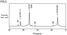
- the XRD data of the Al-rich layer presents as a maximum peak the (200) plane of the hard particles included in the Al-rich layer, for example as shown in Fig. 5 .
- the peak of the (200) plane of c-AlTiN appears with higher intensity than the other planes.
- the reason why it can suppress initial abrasion is unknown in detail.
- the Al-rich layer that transforms into the first unit phase in the form of a plurality of nano-sized lumps and the second unit phase interposed between the lumps of the first unit phase significantly inhibits dislocation movement caused by external stress, and can thus suppress cracking in the coating in an early cutting stage, and also effectively suppress development of cracking toward the substrate when cracking is caused.
- the coating will have a granular structure in which the (200) plane is a maximum peak in XRD analyzed in the direction normal to the surface of the coating, and it is believed that the coating is enhanced in toughness and helps to enhance an effect to further suppress initial abrasion.
- the coating can have an indentation hardness (hereinafter also referred to as "coating strength") of 30 GPa (about 3000 kgf/mm 2 ) or more.
- the coating more preferably has an indentation hardness of 35 GPa.
- the coating having an indentation hardness falling within the above range allows the surface-coated cutting tool to have increased abrasion resistance.
- the cutting tool can exhibit excellent performance when cutting a hard-to-cut material such as a heat-resistant alloy.
- the upper limit of the indentation hardness of the coating is not particularly limited.
- a coating having an indentation hardness of 30 to 38 GPa allows a sufficiently excellent balance between abrasion resistance and chipping resistance.
- This indentation hardness can be measured using a nano-indentation method.
- the indentation hardness can be calculated as follows: an indenter is pushed into the coating by a predetermined load (for example of 30 mN) in a direction perpendicular to that of the thickness of the coating, and an indentation depth by which the indenter is thus pushed in the coating is used to calculate the indentation hardness.
- a predetermined load for example of 30 mN
- the Calo test, oblique lapping, or the like can be performed to remove the other layer to expose the Al-rich layer and the above method can be applied to the exposed Al-rich layer to measure its indentation hardness.
- the surface-coated cutting tool according to the present embodiment that has a substrate coated with a coating having an Al-rich layer including hard particles as described above can have high hardness and be also effectively less likely to have initial abrasion.
- the surface-coated cutting tool can thus be stable and have a long life.
- a method for manufacturing a surface-coated cutting tool according to the present embodiment is according to claim 2.
- the method for manufacturing a surface-coated cutting tool that includes the above-described steps and operations can manufacture a surface-coated cutting tool having high hardness and being also less likely to have initial abrasion.
- the method for manufacturing the surface-coated cutting tool can include another step.
- the other step can for example be a substrate manufacturing step, a surface processing step such as surface-grinding, shot blasting and the like, a CVD step for forming another layer, and the like.
- the other step can be performed in a conventionally known method.
- the "substrate,” “coating,” “Al-rich layer including hard particles,” etc. included in the surface-coated cutting tool manufactured in the above-described manufacturing method are identical to the "substrate,” “coating,” “Al-rich layer including hard particles,” described in the above «surface-coated cutting tool» section.
- each type of step in the present embodiment will be described in detail.
- the method for manufacturing a surface-coated cutting tool includes the step of forming an Al-rich layer.
- the step of forming the Al-rich layer includes a first step of forming a lamellar layer through CVD.
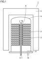
- the lamellar layer can be formed for example by using a CVD apparatus shown in Fig. 1 .
- the lamellar layer is a layer including hard particles, and the hard particle includes a third unit phase and a fourth unit phase, as will be described hereinafter.
- the third unit phase and the fourth unit phase are alternately stacked in the hard particle to form a lamellar phase.
- such a configuration as described above may simply be represented as follows: "the lamellar layer includes a third unit phase and a fourth unit phase.”
- CVD apparatus 1 is provided with a setting table allowing a plurality of substrate setting jigs 3 holding substrates 2 to be set thereon. Substrate 2 and substrate setting jig 3 set on the setting table are covered with a reaction chamber 4. Reaction chamber 4 is surrounded by a temperature control device 5. Temperature control device 5 controls temperature inside reaction chamber 4.
- CVD apparatus 1 is provided with an introduction pipe 8 having two introduction ports 6 and 7.
- Introduction pipe 8 is disposed so as to penetrate the setting table on which substrate setting jig 3 is disposed. A plurality of through holes are formed in a portion near substrate setting jig 3.
- Introduction pipe 8 receives gases through introduction ports 6, 7, and the gases are not mixed therein and instead pass through the through holes and are thus introduced into reaction chamber 4.
- Introduction pipe 8 is rotatable about its axis.
- CVD apparatus 1 is provided with an exhaust pipe 9 to externally discharge exhaust gas through an exhaust port 10.
- the jig and the like in reaction chamber 4 are normally made of graphite.
- the first step it is preferable to perform the following first operation, second operation, and cooling operation using the above-described CVD apparatus.
- a lamellar layer can be formed in the coating, and a cutting tool precursor including this lamellar layer can be obtained.
- another layer such as a TiN layer, an Al 2 O 3 layer, or the like, can also be formed on the substrate using the above described CVD apparatus.
- the substrate any substrate conventionally known as this type of substrate can be used, and accordingly, can be produced in a conventionally known method.
- the first step includes a first operation of obtaining a mixture gas by mixing a first mixture gas and a second mixture gas at 650°C or higher and 850°C or lower with 2 kPa or more and 4 kPa or less applied.
- a first mixture gas containing a source material gas containing Al, a source material gas containing Ti, and a carrier gas is introduced into CVD apparatus 1 through introduction port 6 and thus enters introduction pipe 8.
- the first mixture gas may contain a source material gas containing C (carbon).
- a second mixture gas containing a source material gas containing N and a carrier gas is introduced into CVD apparatus 1 through introduction port 7 and thus enters introduction pipe 8.
- the first mixture gas and the second mixture gas are ejected from introduction pipe 8 into reaction chamber 4 having an atmosphere of 650°C or higher and 850°C or lower and 2 kPa or more and 4 kPa or less, and thus mixed together to provide a mixture gas.
- introduction pipe 8 since introduction pipe 8 has a plurality of through holes, the first mixture gas and second mixture gas introduced are ejected into reaction chamber 4 through different through holes. While the first mixture gas and the second mixture gas are thus ejected, introduction pipe 8 is rotating about its axis as indicated in Fig. 1 by a rotating arrow. A mixture gas in which the first mixture gas and the second mixture gas are uniformly mixed together can thus be obtained. Hence, the mixture gas in which the first mixture gas and the second mixture gas are uniformly mixed together can be deposited in a second operation, which will be described hereinafter, on the side of a surface of substrate 2 set on substrate setting jig 3.
- the source material gas containing Al and the source material gas containing Ti chloride gas of these can suitably be used.
- the source material gas containing C hydrocarbon gas, such as CH 4 and C 2 H 4
- the source material gas containing N nitrogen-containing gas, such as ammonium and N 2
- the first mixture gas includes AlCl 3 gas, TiCl 4 gas, and H 2 gas.
- the first mixture gas can include C 2 H 4 gas in addition to the above gases.
- the second mixture gas includes NH 3 gas and Ar gas.
- the first operation is performed in the reaction chamber having an atmosphere therein with a furnace having an internal temperature of 700°C or higher and 800°C or lower. Further, the furnace preferably has an internal pressure of 3 kPa or more and 4 kPa or less. This will allow the mixture gas to have the first mixture gas and the second mixture gas mixed together more uniformly.
- the first step includes a second operation of ejecting the mixture gas toward the surface of the substrate in the above-described temperature and pressure ranges to form a lamellar layer.
- the source materials (or elements) contained in the mixture gas is deposited on the surface of the substrate.
- a lamellar layer can be formed in the coating, and a cutting tool precursor including the lamellar layer can be obtained.
- the lamellar layer includes a third unit phase and a fourth unit phase.
- the third unit phase and the fourth unit phase are stacked alternately.
- the lamellar layer preferably has a multilayer structure in which the third unit phase and the fourth unit phase are repeatedly stacked.
- the third unit phase is composed of a nitride or carbonitride of Al s Ti 1-s , and has an atomic ratio s of Al of 0.7 or more and 0.95 or less.
- the fourth unit phase is composed of a nitride or carbonitride of Al t Ti 1-t , and has an atomic ratio t of Al of 0.5 or more and less than 0.7.
- the lamellar layer has a multilayer structure composed of the third unit phase and the fourth unit phase stacked repeatedly, the third unit phase appearing dark as it has an atomic ratio of Al (Al/(Al + Ti)) which is relatively high, the fourth unit phase appearing bright as it has an atomic ratio of Al which is lower than that of the third unit phase.
- Fig. 2 the lamellar layer has a multilayer structure composed of the third unit phase and the fourth unit phase stacked repeatedly, the third unit phase appearing dark as it has an atomic ratio of Al (Al/(Al + Ti)) which is relatively high, the fourth unit phase appearing bright as it has an atomic ratio of Al which is lower than that of the third unit phase.
- the third unit phase and the fourth unit phase can be controlled in composition by a ratio at which the source material gases are mixed together.
- the third unit phase and the fourth unit phase can be controlled in thickness and what cycle is applied to stack them by adjusting each source material gas's flow rate and deposition time.
- the number of third and fourth unit phases stacked can be controlled by adjusting introduction pipe 8's rotation rate and the deposition time.
- the first step preferably includes a cooling operation.
- a cooling operation This is because there is a case in which moving the cutting tool precursor may be required to perform each step of the second step, which will be described hereinafter, in a heat treatment furnace (for example, a furnace made of graphite) separate from CVD apparatus 1.
- a heat treatment furnace for example, a furnace made of graphite
- a known means is applicable to the cooling operation.
- temperature control device 5 provided to CVD apparatus 1 can be used to cool substrate 2 set on substrate setting jig 3.
- the cooling operation may be natural cooling by letting the substrate stand. It is preferable to cool the cutting tool precursor to 300°C or lower by this cooling operation.
- the method for manufacturing a surface-coated cutting tool includes a second step of annealing the lamellar layer to obtain an Al-rich layer.
- the second step includes a temperature increasing step, an annealing step, and a cooling step.
- the temperature increasing step includes an operation of increasing the temperature of the lamellar layer at a rate of 10°C/min. or more.
- the temperature increasing step for example, after the cutting tool precursor is removed from the CVD apparatus, it is introduced into the above heat treatment furnace (for example, a furnace made of graphite), and the temperature inside the furnace made of graphite is increased to 700°C or higher and 1200°C or lower at a rate of 10°C/min. or more.
- a temperature increasing rate of less than 10°C/min. may result in a poor yield of the Al-rich layer in the annealing step, which will be described hereinafter.
- the temperature increasing rate is preferably 15°C/min. or more.
- the upper limit of the temperature increasing rate is 30°C/min. If the temperature increasing rate exceeds 30°C/min., carburization tends to reduce the surface-coated cutting tool in strength as a whole.
- the annealing step includes an operation of annealing the lamellar layer at 700°C or higher and 1200°C or lower for 0.1 hour or more and 10 hours or less to obtain an Al-rich layer.
- a heat treatment is performed to maintain the cutting tool precursor that is heated to 700°C or higher and 1200°C or lower at that temperature for 0.1 hour or more and 10 hours or less.
- An annealing step performed at a temperature lower than 700°C and maintained for less than 0.1 hour tends to provide a poor yield of the Al-rich layer.
- An annealing step performed at a temperature exceeding 1200°C and maintained for more than 10 hours tends to cause the lamellar phase to make phase transition to a phase having a wurtzite crystal structure.
- the annealing step is preferably performed at 850°C or higher and 1100°C or lower and maintained for 0.5 hour or more and 2 hours or less. Note, however, that while the annealing step is maintained the annealing step may have a fluctuation in temperature within a range of 700°C to 1200°C, and the fluctuation may temporarily be less than 700°C or exceed 1200°C insofar as the present invention exhibits its effect(s).
- the cooling step includes an operation of rapidly cooling the Al rich layer at a rate of 20°C/min. or more.
- known cooling means can be used insofar as the means can rapidly cool the Al-rich layer at a rate of 20°C/min. or more.
- the temperature control device with which the above-mentioned graphite furnace is equipped can be used to cool the cutting tool precursor that has undergone the annealing step. In doing so, it is preferable to rapidly cool the cutting tool precursor of 700°C or higher and 1200°C or lower to around room temperature (for example, about 50°C) within 30 minutes, and therefore it is preferable to rapidly cool the Al rich layer at a rate of 35°C/min. or more.
- the upper limit of the rate of rapidly cooling the Al-rich layer is 50°C/min. If the rate of rapidly cooling the Al-rich layer exceeds 50°C/min., the thermal stress generated by the difference between the thermal expansion coefficient of the substrate and that of the coating increases the probability of cracking and may lead to reduction in strength of the surface-coated cutting tool as a whole.
- a furnace in cooling preferably has an internal pressure of 0.5 to 0.9 MPa. More preferably, it is 0.6 to 0.8 MPa.
- a coolant gas can be increased in viscosity, and a forced convection can increase the cooling rate.
- the method for manufacturing a surface-coated cutting tool according to the present embodiment can form a coating having an Al-rich layer including hard particles as described above, and thus form the coating on the substrate to have high hardness and be also less likely to have initial abrasion.
- the surface-coated cutting tool can thus be stable and have a long life.
- samples 1 to 15 each having a coating different in composition and formed under a different condition were fabricated and evaluated in performance.
- samples 1 to 11 correspond to examples
- samples 12 to 15 correspond to comparative examples.
- a substrate A shown in Table 1 below was prepared. Specifically, a raw material powder having a blending composition shown in Table 1 was uniformly agitated and press-formed into a predetermined shape, and thereafter sintered at 1300 to 1500°C for 1 to 2 hours to obtain a cemented carbide substrate having a shape of SEET13T3AGSN-G (manufactured by Sumitomo Electric Hardmetal). SEET13T3AGSN-G is a shape of an indexable cutting insert for milling.
- Table 1 type blending composition (mass %) Co VC Cr 3 C 2 NbC TaC WC substrate A 10.0 - - 0.1 2.0 balance
- a coating was formed on a surface of the substrate obtained above. Specifically, using the CVD apparatus shown in Fig. 1 , the substrate was set on substrate setting jig 3 and a coating was formed on the substrate through CVD.
- a coating other than the Al rich layer (that is, TiN, TiCN, Al 2 O 3 ) was formed under conditions as indicated below in table 2.
- the layers of TiN, TiCN, and Al 2 O 3 were formed on the substrate with each source material gas deposited in an adjusted period of time so that the layers had thickness as indicated in table 6, which will be described hereinafter.
- the AlTiN film was formed on the substrates of samples 14 and 15 through PVD under the following conditions:
- the Al-rich layer was obtained through the above-described step of forming an Al-rich layer. Specifically, it was formed through a first step of forming a lamellar layer through CVD and a second step of annealing the lamellar layer to obtain the Al-rich layer.
- a lamellar layer was formed in the first step.
- the lamellar layer was formed under four conditions of conditions T1 to T4.
- a mixture gas was made from a first mixture gas including AlCl 3 gas, TiCl 4 gas and H 2 gas, and a second mixture gas including NH 3 gas and Ar gas.
- a mixture gas was made from a first mixture gas including AlCl 3 gas, TiCl 4 gas and H 2 gas, and in addition thereto, including C 2 H 4 gas, and a second mixture gas including NH 3 gas and Ar gas.
- a volume ratio of AlCl 3 /(AlCl 3 +TiCl 4 ) in the mixture gas, and conditions of temperature and pressure in CVD apparatus 1 are as shown in table 3.
- the first mixture gas was introduced into CVD apparatus 1 via introduction port 6 to introduction pipe 8, and the second mixture gas was introduced into CVD apparatus 1 via introduction port 7 to introduction pipe 8.
- introduction pipe 8 was rotated to eject the first mixture gas and the second mixture gas through the through holes of introduction pipe 8.
- a mixture gas in which the first mixture gas and the second mixture gas were uniformly mixed together was obtained, and the mixture gas was deposited on the side of the surface of the substrate to form a lamellar layer.
- a lamellar layer in which a third unit phase having a composition of Al 0.86 Ti 0.14 N and a thickness of 5 ⁇ m and a fourth unit phase having a composition of Al 0.6 Ti 0.4 N and a thickness of 2 ⁇ m are repeatedly stacked with the third and fourth unit phases having an average composition of Al 0.8 Ti 0.2 N.
- a lamellar layer was formed on the substrate under condition T1.
- a lamellar layer was formed on the substrate under condition T2.
- a lamellar layer was formed on the substrate under condition T3.
- a lamellar layer was formed on the substrate under condition T4.
- An image of the lamellar layer (or phase) of sample 1 through a transmission electron microscope is shown in Fig. 2 .
- a trade name: "JEM-2100F (manufactured by JEOL Ltd.)" was used.
- the second step was performed to anneal the lamellar layer to obtain an Al-rich layer.
- the Al-rich layer was formed under four conditions of conditions C1 to C4. Under each of conditions C1 to C4, the second step was performed such that the temperature increasing step was performed with a temperature increasing rate, the annealing step was performed with an annealing temperature, an annealing time and an annealing atmosphere, and the cooling step was performed with a cooling rate and the furnace having an internal pressure in cooling, as shown in Table 4.
- the lamellar layer was heated at a temperature increasing rate of 10°C/min. and annealed at 900°C for 60 minutes to obtain an Al-rich layer, and this Al-rich layer was cooled at a cooling rate of 40°C/min. with the furnace having an internal pressure of 0.9 MPa.
- samples 1 and 5 had their lamellar layers subjected to condition C1 to obtain an Al-rich layer.
- Samples 2 and 6-8 had their lamellar layers subjected to condition C2 to obtain an Al-rich layer.
- Samples 3, 9 and 10 had their lamellar layers subjected to condition C3 to obtain an Al-rich layer.
- Sample 11 had its lamellar layer subjected to condition C4 to obtain an Al-rich layer.
- Samples 12 and 13 did not have their lamellar layers subjected to the second step.
- Sample 14 also did not have its PVD-formed AlTiN film subjected to the second step.
- sample 15 had its PVD-formed AlTiN film subjected to a heat treatment such that it was heated, annealed and cooled under condition C1.
- An image of hard particles in the Al rich layer of sample 1 through a transmission electron microscope is shown in Fig. 3 .
- As the transmission electron microscope a trade name: "JEM-2100F (manufactured by JEOL Ltd.)" was used.
- samples 7 and 8 were subjected to a surface treatment by shot blasting under conditions, respectively, shown in Table 5 to apply compressive stress to their coatings.
- sample 1 is a surface-coated cutting tool in which a 1 ⁇ m thick TiN layer was formed directly on substrate A as an underlying layer and a 10 ⁇ m thick Al-rich layer was formed on the TiN layer.
- the surface-coated cutting tool of sample 1 has an Al-rich layer obtained by annealing under condition C1 a lamellar layer formed under condition T1.
- sample 9 is a surface-coated cutting tool in which a 1 ⁇ m thick TiN layer was formed directly on substrate A as an underlying layer, a 3 ⁇ m thick Al 2 O 3 layer was formed on the TiN layer, and a 5 ⁇ m thick Al-rich layer was formed on the Al 2 O 3 layer.
- the surface-coated cutting tool of sample 9 has an Al-rich layer obtained by annealing under condition C3 a lamellar layer formed under condition T3.
- sample 10 is a surface-coated cutting tool in which a 0.5 ⁇ m thick TiN layer was formed directly on substrate A as an underlying layer, a 2 ⁇ m thick TiCN layer was formed on the TiN layer, a 2 ⁇ m thick Al 2 O 3 layer was formed on the TiCN layer, and a 5 ⁇ m thick Al rich layer was formed on the Al 2 O 3 layer.
- the surface-coated cutting tool of sample 10 has an Al-rich layer obtained by annealing under condition C3 a lamellar layer formed under condition T3.
- Table 6 examples /comparative examples base material TiN ( ⁇ m) TiCN ( ⁇ m) Al-rich layer ( ⁇ m) Al 2 O 3 ( ⁇ m) Al-rich layer ( ⁇ m) surface treatment sample 1 A 1 - 10 (T1+C1) - - - sample 2 A 1 - 10 (T1+C2) - - - sample 3 A 1 - 10 (T1+C3) - - - sample 4 A 1 - 10 (T1+C4) - - - sample 5 A 1 - 10 (T2+C1) - - - sample 6 A 0.5 2.5 5.5 (T1+C2) - - - sample 7 A 0.5 2.5 5.5 (T1+C2) - ⁇ sample 8 A 0.5 2.5 5.5 (T1+C2) - ⁇ sample 9 A 1 - - 3 5 (T3+C3) - sample 10 A 0.5 2 - 2 5 (T3+C3) - sample 11 A 1 - 10 (T4+C4) - -
- the surface-coated cutting tools of samples 1 to 11 each had the Al-rich layer analyzed through X-ray diffraction in a direction normal to a surface of the coating to examine which crystal plane presented a maximum diffraction peak.
- the Al-rich layer of the surface-coated cutting tool of each of samples 1 to 11 presented a maximum diffraction peak at the (200) plane.
- Fig. 5 shows a result of X-ray diffraction of the Al-rich layer in the surface-coated cutting tool of sample 1. It is expected that the surface-coated cutting tools of samples 1 to 11 have excellent fracture resistance and can exhibit excellent performance for an application, such as a casting or the like, requiring intermittent working.
- the surface-coated cutting tools of samples 1 to 11 had their Al-rich layers observed with the above-described transmission microscope, and subjected to an elemental analysis with an EDX with which the transmission microscope was equipped. Thereby, atomic ratio x of Al of peaks in the first unit phase of the Al rich layer (as averaged), atomic ratio y of Al of valleys in the second unit phase of the Al rich layer (as averaged), and the first unit phase's size in the ⁇ 100> orientation (as averaged) were measured. A result thereof is shown in table 7.
- the surface-coated cutting tools of samples 1 to 11 had their coatings examined for strength (or indentation hardness) in the method described above. A result thereof is also shown in table 7.
- the surface-coated cutting tools of samples 12 to 15 had no Al-rich layer, and accordingly, they were not subjected to an analysis through X-ray diffraction, an elemental analysis with EDX, or a measurement in size of the first unit phase in the ⁇ 100> orientation, as described above. Note, however, that the surface-coated cutting tools of samples 12 to 15 had their coatings evaluated for strength (or indentation hardness) in the method described above. A result thereof is shown in table 7.
- sample 12 is a surface-coated cutting tool in which substrate A coated with a TiN layer serving as an underlying layer was only subjected to condition T1 to form a coating
- sample 13 is a surface-coated cutting tool in which substrate A coated with a TiN layer serving as an underlying layer was only subjected to condition T4 to form a coating.
- Sample 14 is a surface-coated cutting tool in which substrate A coated with a TiN layer serving as an underlying layer was subjected to the above described, conditioned PVD to form an AlTiN layer
- sample 15 is a surface-coated cutting tool in which substrate A coated with a TiN layer serving as an underlying layer was subjected to the above described, conditioned PVD to form an AlTiN layer and subsequently underwent a heat treatment under condition C1 to form a coating.
- sample 1 has an Al-rich layer composed of hard particles having a first unit phase presenting a peak with an atomic ratio x of Al of 0.9 (that is, Al 0.9 Ti 0.1 N) and a second unit phase presenting a valley with an atomic ratio y of Al of 0.56 (that is, Al 0.56 Ti 0.44 N). Furthermore, the first unit phase has a size of 8 nm in the ⁇ 100> orientation. Sample 1 had an Al-rich layer with the coating having a strength (or indentation hardness) of 34 GPa.
- samples 1 to 11 each had an Al-rich layer with the coating superior in strength to samples 12 to 15.
- the surface-coated cutting tools of samples 1 to 15 underwent a cutting test (an abrasion resistance test) under the following cutting conditions: Specifically, the surface coated cutting tools of samples 1 to 15 (shape: SEET13T3AGSN-G) were used under conditions as indicated below to measure a cuttable time before the cutting tools had a flank face worn by an amount (Vb) of 0.30 mm. A result thereof is shown in table 8. The table shows that a surface-coated cutting tool having a longer cuttable time suppresses initial abrasion and thus has larger abrasion resistance.
Landscapes
- Chemical & Material Sciences (AREA)
- Engineering & Computer Science (AREA)
- Mechanical Engineering (AREA)
- Metallurgy (AREA)
- Materials Engineering (AREA)
- Chemical Kinetics & Catalysis (AREA)
- General Chemical & Material Sciences (AREA)
- Organic Chemistry (AREA)
- Inorganic Chemistry (AREA)
- Cutting Tools, Boring Holders, And Turrets (AREA)
- Chemical Vapour Deposition (AREA)
- Drilling Tools (AREA)
- Milling, Broaching, Filing, Reaming, And Others (AREA)
Claims (2)
- Oberflächen beschichtetes Schneidwerkzeug, das ein Substrat und eine auf einer Oberfläche des Substrats ausgebildete Beschichtung umfasst,wobei die Beschichtung ein oder zwei oder mehr Schichten umfasst,wobei wenigstens eine der Schichten eine Al-reiche Schicht mit darin enthaltenen harten Partikeln ist, wobei die harten Partikeln 50 Vol-% oder mehr und 95 Vol-% oder weniger der Al-reichen Schicht einnehmen, wobei die Vol-% unter Verwendung der in der Beschreibung beschriebenen Methode bestimmt werden und wobei die harten Partikeln einen Partikeldurchmesser von 10 nm oder mehr und 1000 nm oder weniger aufweisen, wobei der Partikeldurchmesser unter Verwendung der in der Beschreibung beschriebenen Methode bestimmt wird,wobei die harten Partikeln eine Kristallstruktur des Natriumchlorid-Typs aufweisen und eine erste Einheitsphase in der Form einer Vielzahl von Klumpen und eine zwischen den Klumpen der ersten Einheitsphase angeordnete zweite Einheitsphase aufweisen,wobei die erste Einheitsphase aus einem Nitrid oder Carbonitrid von AlxTi1-x besteht, wobei die erste Einheitsphase ein Atomverhältnis x von Al von 0,7 oder mehr und 0,96 oder weniger aufweist, wobei das Atomverhältnis unter Verwendung der in der Beschreibung beschriebenen Methode bestimmt wird,wobei die Größe der ersten Einheitsphase 2 nm oder größer und 15 nm oder kleiner in der <100>-Ausrichtung ist, wobei die Größe der ersten Einheitsphase unter Verwendung der in der Beschreibung beschriebenen TEM-Bildmethode bestimmt wird,wobei die zweite Einheitsphase aus einem Nitrid oder einem Carbonitrid von AlyTi1-y besteht,wobei die zweite Einheitsphase ein Atomverhältnis y von Al von über 0,5 und kleiner als 0,7 aufweist, wobei das Atomverhältnis unter Verwendung der in der Beschreibung beschriebenen Methode bestimmt wird,wobei die Al-reiche Schicht eine maximale Spitze in der (200)-Ebene aufweist, wenn die Al-reiche Schicht durch eine Röntgendiffraktometrie in der Richtung normal zu der Oberfläche der Beschichtung analysiert wird, wobei die Röntgendiffraktometrie unter Verwendung der in der Beschreibung beschriebenen Methode durchgeführt wird,wobei die Al-reiche Schicht eine Dicke von 1 µm oder mehr und 20 µm oder weniger aufweist, wobei die Dicke unter Verwendung der in der Beschreibung beschriebenen Methode bestimmt wird,wobei das harte Partikel intern eine Struktur aufweist, in der die zweite Einheitsphase in der Form einer dünnen Linie die erste Einheitsphase in der Form einer Vielzahl von Klumpen umgibt, undwobei die Anzahl von Klumpen der ersten Einheitsphase, die durch die zweite Einheitsphase in der <100>-Ausrichtung umgeben ist, 10 oder mehr oder 1000 oder weniger beträgt, wobei die Anzahl von Klumpen unter Verwendung der in der Beschreibung beschriebenen Methode, die TEM-Bilder von drei verschiedenen Sichtfeldern für das Bestimmen eines Durchschnittswerts verwendet, bestimmt wird.
- Verfahren zum Herstellen des oberflächenbeschichteten Schneidwerkzeugs gemäß dem Anspruch 1, wobei das Verfahren die folgenden Schritte umfasst:Ausbilden der Al-reichen Schicht,wobei der Schritt zum Ausbilden der Al-reichen Schicht umfasst:einen ersten Schritt zum Ausbilden einer lamellaren Schicht mittels einer chemischen Gasphasenabscheidung, undeinen zweiten Schritt zum Glühen der lamellaren Schicht für das Erhalten der Al-reichen Schicht,wobei der zweite Schritt einen Temperaturerhöhungsschritt, einen Glühschritt und einen Abkühlschritt umfasst,wobei der Temperaturerhöhungsschritt eine Operation zum Erhöhen der Temperatur der lamellaren Schicht mit einer Rate von 10°C/min oder mehr und 30°C/min oder weniger umfasst,wobei der Glühschritt eine Operation zum Glühen der lamellaren Schicht bei 700°C oder höher und 1200°C oder niedriger für 0,1 Stunden oder mehr und 10 Stunden oder weniger für das Erhalten der Al-reichen Schicht umfasst,wobei der Abkühlschritt eine Operation zum schnellen Kühlen der Al-reichen Schicht mit einer Rate von 20°C/min oder mehr und 50°C/min oder weniger umfasst,wobei der erste Schritt umfasst:eine erste Operation zum Erhalten eines Mischgases durch das Mischen eines ersten Mischgases und eines zweiten Mischgases mit einer Temperatur im Bereich von 650°C bis 850°C bei einem ausgeübten Druck im Bereich von 2 kPa bis 4 kPa, undeine zweite Operation zum Ausstoßen des Mischgases zu einer Oberfläche des Substrats mit der Temperatur mit dem ausgeübten Druck für das Bilden der lamellaren Schicht,wobei das erste Mischgas ein AlCl3-Gas, TiCl4-Gas und H2-Gas enthält, undwobei das zweite Mischgas ein NH3-Gas und ein Ar-Gas enthält,wobei die lamellare Schicht eine dritte Einheitsphase und eine vierte Einheitsphase enthält,wobei die dritte Einheitsphase und die vierte Einheitsphase alternierend gestapelt werden, wie mittels einer Transmissionselektronenmikroskopie unter Verwendung der in der Beschreibung beschriebenen Methode gezeigt,wobei die dritte Einheitsphase aus einem Nitrid oder Carbonitrid von AlsTi1-s besteht,wobei die dritte Einheitsphase ein Atomverhältnis s von Al von 0,7 oder mehr und 0,95 oder weniger aufweist, wobei das Atomverhältnis s unter Verwendung der in der Beschreibung beschriebenen Methode bestimmt wird,wobei die vierte Einheitsphase aus einem Nitrid oder Carbonitrid von AltTi1-t besteht, undwobei die vierte Einheitsphase ein Atomverhältnis t von Al von 0,5 oder mehr und weniger als 0,7 aufweist, wobei das Atomverhältnis t unter Verwendung der in der Beschreibung beschriebenen Methode bestimmt wird.
Applications Claiming Priority (2)
| Application Number | Priority Date | Filing Date | Title |
|---|---|---|---|
| JP2017037375 | 2017-02-28 | ||
| PCT/JP2017/024935 WO2018158974A1 (ja) | 2017-02-28 | 2017-07-07 | 表面被覆切削工具およびその製造方法 |
Publications (3)
| Publication Number | Publication Date |
|---|---|
| EP3590636A1 EP3590636A1 (de) | 2020-01-08 |
| EP3590636A4 EP3590636A4 (de) | 2021-01-13 |
| EP3590636B1 true EP3590636B1 (de) | 2025-03-12 |
Family
ID=63370624
Family Applications (1)
| Application Number | Title | Priority Date | Filing Date |
|---|---|---|---|
| EP17898614.7A Active EP3590636B1 (de) | 2017-02-28 | 2017-07-07 | Oberflächenbeschichtetes schneidwerkzeug und herstellungsverfahren dafür |
Country Status (6)
| Country | Link |
|---|---|
| US (1) | US11123802B2 (de) |
| EP (1) | EP3590636B1 (de) |
| JP (1) | JP6831448B2 (de) |
| KR (1) | KR102232131B1 (de) |
| CN (1) | CN110352107B (de) |
| WO (1) | WO2018158974A1 (de) |
Families Citing this family (7)
| Publication number | Priority date | Publication date | Assignee | Title |
|---|---|---|---|---|
| WO2018158976A1 (ja) * | 2017-02-28 | 2018-09-07 | 住友電工ハードメタル株式会社 | 表面被覆切削工具およびその製造方法 |
| JP6831449B2 (ja) * | 2017-02-28 | 2021-02-17 | 住友電工ハードメタル株式会社 | 表面被覆切削工具およびその製造方法 |
| US20210046553A1 (en) * | 2019-04-19 | 2021-02-18 | Sumitomo Electric Hardmetal Corp. | Cutting tool |
| US20210046561A1 (en) * | 2019-04-19 | 2021-02-18 | Sumitomo Electric Hardmetal Corp. | Cutting tool |
| CN114929415B (zh) * | 2020-01-08 | 2024-10-18 | 住友电工硬质合金株式会社 | 切削工具 |
| EP4610393A1 (de) * | 2024-02-28 | 2025-09-03 | BOEHLERIT GmbH & Co.KG. | Verfahren zum beschichten eines objektes und damit hergestelltes objekt |
| AT528040A1 (de) * | 2024-02-28 | 2025-09-15 | Boehlerit Gmbh & Co Kg | Beschichtetes Objekt und Verfahren zu dessen Herstellung |
Family Cites Families (20)
| Publication number | Priority date | Publication date | Assignee | Title |
|---|---|---|---|---|
| AU512633B2 (en) | 1976-12-21 | 1980-10-23 | Sumitomo Electric Industries, Ltd. | Sintered tool |
| US5958569A (en) * | 1995-10-27 | 1999-09-28 | Teledyne Industries, Inc. | Anchored oxide coatings on hard metal cutting tools |
| EP1992717B1 (de) * | 2000-12-28 | 2012-02-15 | Kabushiki Kaisha Kobe Seiko Sho | Verwendung eines Targets zur Lichtbogenionenplattierung für die Herstellung eines Hartfilms |
| JP2003071609A (ja) * | 2001-08-31 | 2003-03-12 | Mitsubishi Materials Corp | 高速切削ですぐれた耐熱塑性変形性を発揮する表面被覆超硬合金製切削工具 |
| JP3996809B2 (ja) * | 2002-07-11 | 2007-10-24 | 住友電工ハードメタル株式会社 | 被覆切削工具 |
| JP2005131730A (ja) * | 2003-10-30 | 2005-05-26 | Mitsubishi Materials Corp | 硬質被覆層がすぐれた耐チッピング性を有する表面被覆サーメット製切削工具 |
| DE102005032860B4 (de) | 2005-07-04 | 2007-08-09 | Fraunhofer-Gesellschaft zur Förderung der angewandten Forschung e.V. | Hartstoffbeschichtete Körper und Verfahren zu deren Herstellung |
| DE102007000512B3 (de) * | 2007-10-16 | 2009-01-29 | Fraunhofer-Gesellschaft zur Förderung der angewandten Forschung e.V. | Hartstoffbeschichtete Körper und Verfahren zu deren Herstellung |
| DE102009046667B4 (de) * | 2009-11-12 | 2016-01-28 | Fraunhofer-Gesellschaft zur Förderung der angewandten Forschung e.V. | Beschichtete Körper aus Metall, Hartmetal, Cermet oder Keramik sowie Verfahren zur Beschichtung derartiger Körper |
| US8409702B2 (en) * | 2011-02-07 | 2013-04-02 | Kennametal Inc. | Cubic aluminum titanium nitride coating and method of making same |
| AT511950B1 (de) | 2012-03-14 | 2013-04-15 | Boehlerit Gmbh & Co Kg | Beschichteter Körper und Verfahren zum Beschichten eines Körpers |
| JP5618429B2 (ja) | 2012-12-28 | 2014-11-05 | 住友電工ハードメタル株式会社 | 表面被覆部材およびその製造方法 |
| JP6206800B2 (ja) * | 2013-09-05 | 2017-10-04 | 住友電工ハードメタル株式会社 | 被膜の製造方法 |
| DE102014103220A1 (de) * | 2014-03-11 | 2015-09-17 | Walter Ag | TiAIN-Schichten mit Lamellenstruktur |
| JP5924507B2 (ja) | 2014-09-25 | 2016-05-25 | 三菱マテリアル株式会社 | 硬質被覆層がすぐれた耐チッピング性を発揮する表面被覆切削工具 |
| JP6120229B2 (ja) * | 2015-01-14 | 2017-04-26 | 住友電工ハードメタル株式会社 | 硬質被膜、切削工具および硬質被膜の製造方法 |
| US10662524B2 (en) | 2015-07-27 | 2020-05-26 | Walter Ag | Tool with TiAIN coating |
| JP2017037375A (ja) | 2015-08-07 | 2017-02-16 | キヤノン株式会社 | 撮像装置及びその制御方法 |
| JP6037256B1 (ja) | 2016-04-14 | 2016-12-07 | 住友電工ハードメタル株式会社 | 表面被覆切削工具およびその製造方法 |
| JP6045010B1 (ja) | 2016-04-14 | 2016-12-14 | 住友電工ハードメタル株式会社 | 表面被覆切削工具およびその製造方法 |
-
2017
- 2017-07-07 US US16/489,312 patent/US11123802B2/en active Active
- 2017-07-07 WO PCT/JP2017/024935 patent/WO2018158974A1/ja not_active Ceased
- 2017-07-07 JP JP2019502435A patent/JP6831448B2/ja active Active
- 2017-07-07 KR KR1020197024753A patent/KR102232131B1/ko active Active
- 2017-07-07 EP EP17898614.7A patent/EP3590636B1/de active Active
- 2017-07-07 CN CN201780087549.0A patent/CN110352107B/zh active Active
Also Published As
| Publication number | Publication date |
|---|---|
| US11123802B2 (en) | 2021-09-21 |
| KR20190112037A (ko) | 2019-10-02 |
| JP6831448B2 (ja) | 2021-02-17 |
| EP3590636A1 (de) | 2020-01-08 |
| CN110352107B (zh) | 2021-06-25 |
| CN110352107A (zh) | 2019-10-18 |
| KR102232131B1 (ko) | 2021-03-24 |
| EP3590636A4 (de) | 2021-01-13 |
| US20200061718A1 (en) | 2020-02-27 |
| JPWO2018158974A1 (ja) | 2019-08-08 |
| WO2018158974A1 (ja) | 2018-09-07 |
Similar Documents
| Publication | Publication Date | Title |
|---|---|---|
| EP3590636B1 (de) | Oberflächenbeschichtetes schneidwerkzeug und herstellungsverfahren dafür | |
| EP3441167B1 (de) | Oberflächenbeschichtetes schneidwerkzeug und verfahren zur herstellung davon | |
| EP3444052B1 (de) | Oberflächenbeschichtetes schneidwerkzeug und herstellungsverfahren dafür | |
| EP2570511B2 (de) | Kornrandmanipuliertes alpha-aluminbeschichtetes Schneidwerkzeug | |
| EP3590638B1 (de) | Oberflächenbeschichtetes schneidwerkzeug und verfahren zur herstellung desselben | |
| KR20180123092A (ko) | 표면 피복 절삭 공구 및 그 제조 방법 | |
| US11020804B2 (en) | Surface-coated cutting tool and method for manufacturing the same | |
| WO2017179220A1 (ja) | 表面被覆切削工具およびその製造方法 | |
| CN115397589B (zh) | 表面包覆切削工具 | |
| JP7486045B2 (ja) | 表面被覆切削工具 | |
| WO2020158426A1 (ja) | 切削工具及びその製造方法 |
Legal Events
| Date | Code | Title | Description |
|---|---|---|---|
| STAA | Information on the status of an ep patent application or granted ep patent |
Free format text: STATUS: THE INTERNATIONAL PUBLICATION HAS BEEN MADE |
|
| PUAI | Public reference made under article 153(3) epc to a published international application that has entered the european phase |
Free format text: ORIGINAL CODE: 0009012 |
|
| STAA | Information on the status of an ep patent application or granted ep patent |
Free format text: STATUS: REQUEST FOR EXAMINATION WAS MADE |
|
| 17P | Request for examination filed |
Effective date: 20190812 |
|
| AK | Designated contracting states |
Kind code of ref document: A1 Designated state(s): AL AT BE BG CH CY CZ DE DK EE ES FI FR GB GR HR HU IE IS IT LI LT LU LV MC MK MT NL NO PL PT RO RS SE SI SK SM TR |
|
| AX | Request for extension of the european patent |
Extension state: BA ME |
|
| DAV | Request for validation of the european patent (deleted) | ||
| DAX | Request for extension of the european patent (deleted) | ||
| A4 | Supplementary search report drawn up and despatched |
Effective date: 20201216 |
|
| RIC1 | Information provided on ipc code assigned before grant |
Ipc: C23C 16/36 20060101ALI20201210BHEP Ipc: B23D 77/00 20060101ALI20201210BHEP Ipc: C23C 16/56 20060101ALI20201210BHEP Ipc: B23B 51/00 20060101ALI20201210BHEP Ipc: B23B 27/14 20060101AFI20201210BHEP Ipc: B23F 21/00 20060101ALI20201210BHEP Ipc: B23C 5/16 20060101ALI20201210BHEP Ipc: C23C 16/34 20060101ALI20201210BHEP Ipc: B23G 5/06 20060101ALI20201210BHEP |
|
| STAA | Information on the status of an ep patent application or granted ep patent |
Free format text: STATUS: EXAMINATION IS IN PROGRESS |
|
| 17Q | First examination report despatched |
Effective date: 20231019 |
|
| GRAP | Despatch of communication of intention to grant a patent |
Free format text: ORIGINAL CODE: EPIDOSNIGR1 |
|
| STAA | Information on the status of an ep patent application or granted ep patent |
Free format text: STATUS: GRANT OF PATENT IS INTENDED |
|
| INTG | Intention to grant announced |
Effective date: 20241028 |
|
| P01 | Opt-out of the competence of the unified patent court (upc) registered |
Free format text: CASE NUMBER: APP_65000/2024 Effective date: 20241209 |
|
| GRAS | Grant fee paid |
Free format text: ORIGINAL CODE: EPIDOSNIGR3 |
|
| GRAA | (expected) grant |
Free format text: ORIGINAL CODE: 0009210 |
|
| STAA | Information on the status of an ep patent application or granted ep patent |
Free format text: STATUS: THE PATENT HAS BEEN GRANTED |
|
| AK | Designated contracting states |
Kind code of ref document: B1 Designated state(s): AL AT BE BG CH CY CZ DE DK EE ES FI FR GB GR HR HU IE IS IT LI LT LU LV MC MK MT NL NO PL PT RO RS SE SI SK SM TR |
|
| REG | Reference to a national code |
Ref country code: GB Ref legal event code: FG4D |
|
| REG | Reference to a national code |
Ref country code: CH Ref legal event code: EP |
|
| REG | Reference to a national code |
Ref country code: DE Ref legal event code: R096 Ref document number: 602017088347 Country of ref document: DE |
|
| REG | Reference to a national code |
Ref country code: IE Ref legal event code: FG4D |
|
| REG | Reference to a national code |
Ref country code: SE Ref legal event code: TRGR |
|
| PG25 | Lapsed in a contracting state [announced via postgrant information from national office to epo] |
Ref country code: RS Free format text: LAPSE BECAUSE OF FAILURE TO SUBMIT A TRANSLATION OF THE DESCRIPTION OR TO PAY THE FEE WITHIN THE PRESCRIBED TIME-LIMIT Effective date: 20250612 |
|
| PG25 | Lapsed in a contracting state [announced via postgrant information from national office to epo] |
Ref country code: FI Free format text: LAPSE BECAUSE OF FAILURE TO SUBMIT A TRANSLATION OF THE DESCRIPTION OR TO PAY THE FEE WITHIN THE PRESCRIBED TIME-LIMIT Effective date: 20250312 |
|
| PG25 | Lapsed in a contracting state [announced via postgrant information from national office to epo] |
Ref country code: ES Free format text: LAPSE BECAUSE OF FAILURE TO SUBMIT A TRANSLATION OF THE DESCRIPTION OR TO PAY THE FEE WITHIN THE PRESCRIBED TIME-LIMIT Effective date: 20250312 |
|
| REG | Reference to a national code |
Ref country code: LT Ref legal event code: MG9D |
|
| PG25 | Lapsed in a contracting state [announced via postgrant information from national office to epo] |
Ref country code: NO Free format text: LAPSE BECAUSE OF FAILURE TO SUBMIT A TRANSLATION OF THE DESCRIPTION OR TO PAY THE FEE WITHIN THE PRESCRIBED TIME-LIMIT Effective date: 20250612 |
|
| PG25 | Lapsed in a contracting state [announced via postgrant information from national office to epo] |
Ref country code: HR Free format text: LAPSE BECAUSE OF FAILURE TO SUBMIT A TRANSLATION OF THE DESCRIPTION OR TO PAY THE FEE WITHIN THE PRESCRIBED TIME-LIMIT Effective date: 20250312 |
|
| REG | Reference to a national code |
Ref country code: NL Ref legal event code: MP Effective date: 20250312 |
|
| PG25 | Lapsed in a contracting state [announced via postgrant information from national office to epo] |
Ref country code: LV Free format text: LAPSE BECAUSE OF FAILURE TO SUBMIT A TRANSLATION OF THE DESCRIPTION OR TO PAY THE FEE WITHIN THE PRESCRIBED TIME-LIMIT Effective date: 20250312 |
|
| PG25 | Lapsed in a contracting state [announced via postgrant information from national office to epo] |
Ref country code: GR Free format text: LAPSE BECAUSE OF FAILURE TO SUBMIT A TRANSLATION OF THE DESCRIPTION OR TO PAY THE FEE WITHIN THE PRESCRIBED TIME-LIMIT Effective date: 20250613 Ref country code: BG Free format text: LAPSE BECAUSE OF FAILURE TO SUBMIT A TRANSLATION OF THE DESCRIPTION OR TO PAY THE FEE WITHIN THE PRESCRIBED TIME-LIMIT Effective date: 20250312 |
|
| PGFP | Annual fee paid to national office [announced via postgrant information from national office to epo] |
Ref country code: SE Payment date: 20250528 Year of fee payment: 9 |
|
| REG | Reference to a national code |
Ref country code: AT Ref legal event code: MK05 Ref document number: 1774605 Country of ref document: AT Kind code of ref document: T Effective date: 20250312 |
|
| PG25 | Lapsed in a contracting state [announced via postgrant information from national office to epo] |
Ref country code: NL Free format text: LAPSE BECAUSE OF FAILURE TO SUBMIT A TRANSLATION OF THE DESCRIPTION OR TO PAY THE FEE WITHIN THE PRESCRIBED TIME-LIMIT Effective date: 20250312 |
|
| PG25 | Lapsed in a contracting state [announced via postgrant information from national office to epo] |
Ref country code: SM Free format text: LAPSE BECAUSE OF FAILURE TO SUBMIT A TRANSLATION OF THE DESCRIPTION OR TO PAY THE FEE WITHIN THE PRESCRIBED TIME-LIMIT Effective date: 20250312 |
|
| PG25 | Lapsed in a contracting state [announced via postgrant information from national office to epo] |
Ref country code: PT Free format text: LAPSE BECAUSE OF FAILURE TO SUBMIT A TRANSLATION OF THE DESCRIPTION OR TO PAY THE FEE WITHIN THE PRESCRIBED TIME-LIMIT Effective date: 20250714 |
|
| PGFP | Annual fee paid to national office [announced via postgrant information from national office to epo] |
Ref country code: DE Payment date: 20250528 Year of fee payment: 9 |
|
| PG25 | Lapsed in a contracting state [announced via postgrant information from national office to epo] |
Ref country code: IT Free format text: LAPSE BECAUSE OF FAILURE TO SUBMIT A TRANSLATION OF THE DESCRIPTION OR TO PAY THE FEE WITHIN THE PRESCRIBED TIME-LIMIT Effective date: 20250312 Ref country code: PL Free format text: LAPSE BECAUSE OF FAILURE TO SUBMIT A TRANSLATION OF THE DESCRIPTION OR TO PAY THE FEE WITHIN THE PRESCRIBED TIME-LIMIT Effective date: 20250312 |
|
| PG25 | Lapsed in a contracting state [announced via postgrant information from national office to epo] |
Ref country code: AT Free format text: LAPSE BECAUSE OF FAILURE TO SUBMIT A TRANSLATION OF THE DESCRIPTION OR TO PAY THE FEE WITHIN THE PRESCRIBED TIME-LIMIT Effective date: 20250312 |
|
| PG25 | Lapsed in a contracting state [announced via postgrant information from national office to epo] |
Ref country code: EE Free format text: LAPSE BECAUSE OF FAILURE TO SUBMIT A TRANSLATION OF THE DESCRIPTION OR TO PAY THE FEE WITHIN THE PRESCRIBED TIME-LIMIT Effective date: 20250312 Ref country code: CZ Free format text: LAPSE BECAUSE OF FAILURE TO SUBMIT A TRANSLATION OF THE DESCRIPTION OR TO PAY THE FEE WITHIN THE PRESCRIBED TIME-LIMIT Effective date: 20250312 |
|
| PG25 | Lapsed in a contracting state [announced via postgrant information from national office to epo] |
Ref country code: RO Free format text: LAPSE BECAUSE OF FAILURE TO SUBMIT A TRANSLATION OF THE DESCRIPTION OR TO PAY THE FEE WITHIN THE PRESCRIBED TIME-LIMIT Effective date: 20250312 |
|
| PG25 | Lapsed in a contracting state [announced via postgrant information from national office to epo] |
Ref country code: SK Free format text: LAPSE BECAUSE OF FAILURE TO SUBMIT A TRANSLATION OF THE DESCRIPTION OR TO PAY THE FEE WITHIN THE PRESCRIBED TIME-LIMIT Effective date: 20250312 |
|
| PG25 | Lapsed in a contracting state [announced via postgrant information from national office to epo] |
Ref country code: IS Free format text: LAPSE BECAUSE OF FAILURE TO SUBMIT A TRANSLATION OF THE DESCRIPTION OR TO PAY THE FEE WITHIN THE PRESCRIBED TIME-LIMIT Effective date: 20250712 |
|
| REG | Reference to a national code |
Ref country code: DE Ref legal event code: R097 Ref document number: 602017088347 Country of ref document: DE |
|
| PG25 | Lapsed in a contracting state [announced via postgrant information from national office to epo] |
Ref country code: DK Free format text: LAPSE BECAUSE OF FAILURE TO SUBMIT A TRANSLATION OF THE DESCRIPTION OR TO PAY THE FEE WITHIN THE PRESCRIBED TIME-LIMIT Effective date: 20250312 |
|
| PLBE | No opposition filed within time limit |
Free format text: ORIGINAL CODE: 0009261 |
|
| STAA | Information on the status of an ep patent application or granted ep patent |
Free format text: STATUS: NO OPPOSITION FILED WITHIN TIME LIMIT |
|
| REG | Reference to a national code |
Ref country code: CH Ref legal event code: L10 Free format text: ST27 STATUS EVENT CODE: U-0-0-L10-L00 (AS PROVIDED BY THE NATIONAL OFFICE) Effective date: 20260121 |
|
| 26N | No opposition filed |
Effective date: 20251215 |
|
| REG | Reference to a national code |
Ref country code: CH Ref legal event code: H13 Free format text: ST27 STATUS EVENT CODE: U-0-0-H10-H13 (AS PROVIDED BY THE NATIONAL OFFICE) Effective date: 20260224 |
|
| PG25 | Lapsed in a contracting state [announced via postgrant information from national office to epo] |
Ref country code: LU Free format text: LAPSE BECAUSE OF NON-PAYMENT OF DUE FEES Effective date: 20250707 |
|
| GBPC | Gb: european patent ceased through non-payment of renewal fee |
Effective date: 20250707 |
|
| REG | Reference to a national code |
Ref country code: BE Ref legal event code: MM Effective date: 20250731 |
|
| PG25 | Lapsed in a contracting state [announced via postgrant information from national office to epo] |
Ref country code: GB Free format text: LAPSE BECAUSE OF NON-PAYMENT OF DUE FEES Effective date: 20250707 |
|
| PG25 | Lapsed in a contracting state [announced via postgrant information from national office to epo] |
Ref country code: BE Free format text: LAPSE BECAUSE OF NON-PAYMENT OF DUE FEES Effective date: 20250731 |
|
| PG25 | Lapsed in a contracting state [announced via postgrant information from national office to epo] |
Ref country code: FR Free format text: LAPSE BECAUSE OF NON-PAYMENT OF DUE FEES Effective date: 20250731 |
|
| PG25 | Lapsed in a contracting state [announced via postgrant information from national office to epo] |
Ref country code: CH Free format text: LAPSE BECAUSE OF NON-PAYMENT OF DUE FEES Effective date: 20250731 |