EP3590649A2 - Système de protection pour machine de découpe laser - Google Patents
Système de protection pour machine de découpe laser Download PDFInfo
- Publication number
- EP3590649A2 EP3590649A2 EP19171589.5A EP19171589A EP3590649A2 EP 3590649 A2 EP3590649 A2 EP 3590649A2 EP 19171589 A EP19171589 A EP 19171589A EP 3590649 A2 EP3590649 A2 EP 3590649A2
- Authority
- EP
- European Patent Office
- Prior art keywords
- laser
- assembly
- protective enclosure
- cutting tool
- laser cutting
- Prior art date
- Legal status (The legal status is an assumption and is not a legal conclusion. Google has not performed a legal analysis and makes no representation as to the accuracy of the status listed.)
- Pending
Links
Images







Classifications
-
- B—PERFORMING OPERATIONS; TRANSPORTING
- B23—MACHINE TOOLS; METAL-WORKING NOT OTHERWISE PROVIDED FOR
- B23K—SOLDERING OR UNSOLDERING; WELDING; CLADDING OR PLATING BY SOLDERING OR WELDING; CUTTING BY APPLYING HEAT LOCALLY, e.g. FLAME CUTTING; WORKING BY LASER BEAM
- B23K26/00—Working by laser beam, e.g. welding, cutting or boring
- B23K26/70—Auxiliary operations or equipment
- B23K26/702—Auxiliary equipment
- B23K26/706—Protective screens
-
- B—PERFORMING OPERATIONS; TRANSPORTING
- B23—MACHINE TOOLS; METAL-WORKING NOT OTHERWISE PROVIDED FOR
- B23K—SOLDERING OR UNSOLDERING; WELDING; CLADDING OR PLATING BY SOLDERING OR WELDING; CUTTING BY APPLYING HEAT LOCALLY, e.g. FLAME CUTTING; WORKING BY LASER BEAM
- B23K26/00—Working by laser beam, e.g. welding, cutting or boring
- B23K26/14—Working by laser beam, e.g. welding, cutting or boring using a fluid stream, e.g. a jet of gas, in conjunction with the laser beam; Nozzles therefor
- B23K26/1462—Nozzles; Features related to nozzles
-
- B—PERFORMING OPERATIONS; TRANSPORTING
- B23—MACHINE TOOLS; METAL-WORKING NOT OTHERWISE PROVIDED FOR
- B23K—SOLDERING OR UNSOLDERING; WELDING; CLADDING OR PLATING BY SOLDERING OR WELDING; CUTTING BY APPLYING HEAT LOCALLY, e.g. FLAME CUTTING; WORKING BY LASER BEAM
- B23K26/00—Working by laser beam, e.g. welding, cutting or boring
- B23K26/14—Working by laser beam, e.g. welding, cutting or boring using a fluid stream, e.g. a jet of gas, in conjunction with the laser beam; Nozzles therefor
- B23K26/1462—Nozzles; Features related to nozzles
- B23K26/1482—Detachable nozzles, e.g. exchangeable or provided with breakaway lines
-
- B—PERFORMING OPERATIONS; TRANSPORTING
- B23—MACHINE TOOLS; METAL-WORKING NOT OTHERWISE PROVIDED FOR
- B23K—SOLDERING OR UNSOLDERING; WELDING; CLADDING OR PLATING BY SOLDERING OR WELDING; CUTTING BY APPLYING HEAT LOCALLY, e.g. FLAME CUTTING; WORKING BY LASER BEAM
- B23K26/00—Working by laser beam, e.g. welding, cutting or boring
- B23K26/36—Removing material
- B23K26/38—Removing material by boring or cutting
-
- B—PERFORMING OPERATIONS; TRANSPORTING
- B23—MACHINE TOOLS; METAL-WORKING NOT OTHERWISE PROVIDED FOR
- B23K—SOLDERING OR UNSOLDERING; WELDING; CLADDING OR PLATING BY SOLDERING OR WELDING; CUTTING BY APPLYING HEAT LOCALLY, e.g. FLAME CUTTING; WORKING BY LASER BEAM
- B23K26/00—Working by laser beam, e.g. welding, cutting or boring
- B23K26/70—Auxiliary operations or equipment
-
- B—PERFORMING OPERATIONS; TRANSPORTING
- B23—MACHINE TOOLS; METAL-WORKING NOT OTHERWISE PROVIDED FOR
- B23K—SOLDERING OR UNSOLDERING; WELDING; CLADDING OR PLATING BY SOLDERING OR WELDING; CUTTING BY APPLYING HEAT LOCALLY, e.g. FLAME CUTTING; WORKING BY LASER BEAM
- B23K37/00—Auxiliary devices or processes, not specially adapted for a procedure covered by only one of the other main groups of this subclass
- B23K37/02—Carriages for supporting the welding or cutting element
- B23K37/0211—Carriages for supporting the welding or cutting element travelling on a guide member, e.g. rail, track
- B23K37/0235—Carriages for supporting the welding or cutting element travelling on a guide member, e.g. rail, track the guide member forming part of a portal
-
- B—PERFORMING OPERATIONS; TRANSPORTING
- B23—MACHINE TOOLS; METAL-WORKING NOT OTHERWISE PROVIDED FOR
- B23K—SOLDERING OR UNSOLDERING; WELDING; CLADDING OR PLATING BY SOLDERING OR WELDING; CUTTING BY APPLYING HEAT LOCALLY, e.g. FLAME CUTTING; WORKING BY LASER BEAM
- B23K37/00—Auxiliary devices or processes, not specially adapted for a procedure covered by only one of the other main groups of this subclass
- B23K37/04—Auxiliary devices or processes, not specially adapted for a procedure covered by only one of the other main groups of this subclass for holding or positioning work
- B23K37/0408—Auxiliary devices or processes, not specially adapted for a procedure covered by only one of the other main groups of this subclass for holding or positioning work for planar work
-
- B—PERFORMING OPERATIONS; TRANSPORTING
- B23—MACHINE TOOLS; METAL-WORKING NOT OTHERWISE PROVIDED FOR
- B23K—SOLDERING OR UNSOLDERING; WELDING; CLADDING OR PLATING BY SOLDERING OR WELDING; CUTTING BY APPLYING HEAT LOCALLY, e.g. FLAME CUTTING; WORKING BY LASER BEAM
- B23K37/00—Auxiliary devices or processes, not specially adapted for a procedure covered by only one of the other main groups of this subclass
- B23K37/04—Auxiliary devices or processes, not specially adapted for a procedure covered by only one of the other main groups of this subclass for holding or positioning work
- B23K37/0461—Welding tables
-
- F—MECHANICAL ENGINEERING; LIGHTING; HEATING; WEAPONS; BLASTING
- F16—ENGINEERING ELEMENTS AND UNITS; GENERAL MEASURES FOR PRODUCING AND MAINTAINING EFFECTIVE FUNCTIONING OF MACHINES OR INSTALLATIONS; THERMAL INSULATION IN GENERAL
- F16P—SAFETY DEVICES IN GENERAL; SAFETY DEVICES FOR PRESSES
- F16P1/00—Safety devices independent of the control and operation of any machine
- F16P1/02—Fixed screens or hoods
-
- F—MECHANICAL ENGINEERING; LIGHTING; HEATING; WEAPONS; BLASTING
- F16—ENGINEERING ELEMENTS AND UNITS; GENERAL MEASURES FOR PRODUCING AND MAINTAINING EFFECTIVE FUNCTIONING OF MACHINES OR INSTALLATIONS; THERMAL INSULATION IN GENERAL
- F16P—SAFETY DEVICES IN GENERAL; SAFETY DEVICES FOR PRESSES
- F16P1/00—Safety devices independent of the control and operation of any machine
- F16P1/06—Safety devices independent of the control and operation of any machine specially designed for welding
Definitions
- the present invention relates generally to a protection system and more particularly, to a protection system for a laser cutting machine.
- Laser cutting is a technology that uses a laser to cut materials, and is typically used for industrial manufacturing applications. Laser cutting works by directing the output of a high-power laser most commonly through optics.
- a laser cutting machine features a cutting head generating a laser beam that moves in both of the horizontal dimensions over a workpiece loading onto a table. The focused laser beam is directed to the workpiece, part of which is then melted, burns, and vaporizes away. A cut edge with a high quality surface finish is therefore created.
- Lasers enclosed in the laser cutting machines are capable of emitting high levels of energy and can therefore be dangerous to the eyes and skin of its operator.
- the use of the laser cutting machine can also impose a number of hazards including toxic gases and fumes and inhalable particles.
- the possible random reflection of the laser light may burn the retina of an operator when the laser initially pierces the workpiece. Therefore, coupling a protective enclosure apparatus to a laser cutting machine is essential to the safe operation of the machine.
- Figure 1 illustrates an isomeric side view of a workpiece manipulation apparatus having a laser cutting machine, and its protective enclosure apparatus 100.
- a cutting laser (not shown) is positioned inside a protective enclosure apparatus 101.
- a pallet shuttle 102 locates in close association with the protective enclosure apparatus 101.
- a workpiece can be loaded and unloaded onto and off the pallet shuttle 102.
- the pallet shuttle 102 then carriers the loaded workpiece, enters into and exits the protective enclosure apparatus 101 through a protective enclosure apparatus enclosure door 103.
- the pallet shuttle 102 must exit the protective enclosure apparatus 101.
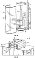
- Figure 2 illustrates an isomeric, side view of a protection system 10, according to one embodiment of the present invention.
- Figure 2 illustrates the protection system 10, as integrated with a laser torch head 80, a bridge 90 for supporting the laser torch head, and a workpiece 91 being processed.
- the laser torch head 80, the bridge 90 and the workpiece 91 are only partially shown in Figure 2 , so as to permit illustration of the protection system itself, and its preferred placement with respect to the bridge 90, the laser torch head 80 and the workpiece 91.
- the protection system 10 of the present invention is moveably mounted to the bridge 90 so as to move therealong.
- the bridge 90 itself is adapted to move in a direction perpendicular to the moving direction of the protection system 10, so as to cut the workpiece 91, as desired.
- the protection system 10 is designed such that the laser cutting head can be mounted on a motorized actuator inside the protection system 10 allowing the laser cutting head to be raised or lowered automatically for the purpose of focusing the laser beam or to accommodate slight variations in thickness of the material to be cut without affecting the position or downward force of the brush guard on the material being cut. This enclosed motorized actuator reduces the risk of accidental exposure of the laser light.
- the protection system 10 includes a frame 11, a top protection assembly 40, a middle protection shield 20, and a bottom protection assembly 60, thereby forming a cavity where a laser torch head 80 locates, so as to prevent the escaping of reflected laser light when the laser torch head 80 cuts the workpiece 91.
- the protection system/enclosure of the present invention does not extend to the apparatus as a whole, nor does the enclosures encompass the movable platen upon which the workpiece is arranged.
- a light shield 23 is a preferably semi-translucent laser safe shield, so as to permit the operator of the laser cutting machine having a view of the inside of the cavity of the protection system 10, meanwhile prevents the reflected laser light escaping from the cavity.
- the light shield includes a planetary gasket 24.
- the light shield 23 is removably fixed to the frame 11 via four interlock switches 22 embedded in the frame 11.
- the middle protection shield assembly 20 is mounted on hinges or vertical slides which are in conjunction with latches, the planetary gasket 24, and safety interlock switches 22, so as to allow interlocked access to the laser head for maintenance while preventing exposure of the laser by an operator.
- the present invention envisions that the light shield 23 is preferably a Laservision P5P10 IR fiber laser safety window, for blocking various light rays across multiple spectrums, although other suitable shielding may be utilized without departing from the broader aspects of the present invention.
- the light shield 23 must be secured to the frame 11 and the interlock switches 22 must be in contact with the light shield 23 in order for the laser torch head 80 to start working. Indeed, the there are several safety switches integrated with the light shield 23, all of which must be actuated in order for the laser head 80 to be permitted to operate.
- Figure 3 illustrates the middle protection shield 20 in an enclosed position.
- the light shield 23 is secured onto the frame 11 via four interlock (safety) switches 22.
- the interlock switches are in a locked position and therefore permits the laser torch head 80 to start working.
- Figure 4 illustrates the middle protection shield 20 in an opened position.
- the light shield 23 is removed from the frame 11.
- the interlock switches trip to an unlocked position upon the detaching of the light shield 23 from the frame 11. Therefore, the laser torch head 80 is unable to start working until the light shield 23 is secured to the frame 11 again.
- the frame 11 is preferably welded so as to provide a continuous housing, thereby preventing radiation from escaping during operation of the laser head 80.
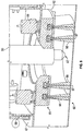
- Figure 5 and 6 in combination, illustrate a sectional view of the top protection assembly 40.
- the top protection assembly 40 includes a top support cover 41 having an opening, and at least brush assembly 44 positioned to cover the opening of the top support cover 41.
- the brush assembly is connected to the top support cover 41 via a bracket 42.
- the brush assembly 44 includes one pair of brush holders 45 which are in connection with the bracket 42, and a pair of brushes 46, each of which comprises a plurality of brush bristles. One end of the brush 46 is received by the brush holder 45 in a brush socket. Two brushes in a pair are positioned in an opposite direction at the same vertical level, so as to permit the other ends of the two brushes to be facing and contacting each other. Therefore, the brushes assembly 44 prevents the reflected laser light from escaping the cavity from the top protection assembly 40, meanwhile permits any electrical cable, light cable or power cable connected to the laser torch head 80 to pass through the top protection assembly 40 and enter into the cavity. The cables therefore can move upward and/or downward freely without congesting the top protection assembly 40.
- three layers of the brushes assembly 44 are arranged vertically and connected to the bracket 42.
- any number of layers can be used to optimize the protection effect of the top protection assembly 40.
- the top protection assembly 40 is connected to the frame 11 via two interlock (safety) switches 48.
- the two interlock switches 48 are in a locked position and permit the laser 80 to start working once the top protection assembly 40 is correctly fixed to the frame. However, if the top protection assembly 40 is removed, the two interlock switches 48 trip to an unlocked position and therefore prevent the laser torch head 80 from starting.
- the top protection assembly 40 may include a solid assembly with the utilities passing through the guard assembly walls by means of bulkhead connectors and plugs, so as to enhance safety and/or provide a more tightly sealed chamber, which can be vented more effectively in the case of unpleasant or toxic fumes generated during the cutting process.
- FIG. 7 and 8 in combination, illustrate the bottom protection assembly 60.
- the bottom protection assembly 60 includes a bottom cover 61 having an opening to permit the laser torch head 80 extending therethrough and applying the laser light onto the workpiece 91 via a laser application tip unit 82.
- the bottom protection assembly 60 further includes a bottom brushes cup assembly 65.
- the bottom cup assembly 65 is arranged in a position relative to the opening on the bottom cover 61 so as to permit the operation of the laser torch head 80 on the workpiece 91.
- the bottom brush cup assembly 65 includes a circular base 62 connected to the bottom cover 61 via two interlock switches 69. An opening in the center of the circular base 62 is matched with the opening on the bottom cover to permit the laser torch head extending therethrough.
- the circular base 62 has at least one socket in a circular shape for receiving an array of brushes 66 arranged in the same circular shape surrounding the central opening on the circular base 62.
- the brushes 66 are attached to the circular base 62 on one end, and extend downward with the other end of the brushes 66 directly contacting the workpiece 91 thereby ensures that the cavity of the protection system 10 is enclosed when the laser torch head 80 is performing cutting function on the workpiece 91.
- the brushes 66 includes a solid rubber membrane 67(122) embedded between the bristles 68. It is yet another important aspect of the present invention that due to the specific use of the brushes 66 and how these bristles/brushes may be compressed to a degree, i.e., slightly bent, when in contact with a workpiece, the protection system 10 of the present invention effectively prevents the reflected laser light from escaping the cavity when the workpiece 91 moves in a vertical direction sporadically during the laser cutting process for the workpiece 91.
- two arrays of brushes are arranged and received in two separate concentric circular sockets locate on the circular base.
- any number of array of brushes and the relevant receiving circular sockets can be arranged, so as to optimize the protection effect of the bottom protection assembly 60.
- the circular base 62 is connected to the bottom cover 61 via two joints and two safety interlock switches 69.
- the two interlock switches 69 are in a locked position and permit the laser torch light 80 to start working once the bottom brushes cup assembly 65 is correctly fixed to the bottom cover 61. However, if the bottom brushes cup assembly 65 is removed, the two interlock switches 69 trip to an unlocked position and therefore prevent the laser torch head 80 from starting.
- the safe operation of the laser head 80 is further increased by arranging a senor (unillustrated) in the area of the base 62, for the purposes of detecting whether a workpiece is positioned adjacent the laser head 80. If the sensor does not detect a workpiece in the area adjacent to the laser head 80, the laser head 80 will not be permitted to operate. Preferably, the laser head 80 will be prevented from operating if the sensor does not detect a workpiece within approximately 1mm below the laser head 80, although it will be readily appreciated that other distances may be instead utilized without departing from the broader aspects of the present invention.
- Figure 9 illustrates a cut-away of the top and bottom portions of the protective enclosure 10.
- the light shield 23 and frame 11 interact and are sized and positioned such that there is an overlap, 100/102, between a raised edge of the frame 11 and the light shield 23, thus ensuring that extraneous light from the laser head 80 does not escape the protective enclosure 10.
- Figure 10 shows an enlarged bottom portion of the protective enclosure 10, as well as a sectional view of one of a pair of spring-loaded bush biasing devices 108.
- the bottom brush cup assembly 65 includes an upper mounting plate 110, which itself is releasably attached to a base mounting plate 112 that is operatively attached to the pair of spring-loaded brush biasing devices 108.
- the spring-loaded brush biasing devices 108 include preferably an articulating ball joint 114 and a biasing spring/element 116.
- the biasing device 108 thereby act to allow the brush cup assembly 65 and integrated bristles to tilt freely while being constantly biased downwardly into contact with the workpiece below, thus accommodating and remaining in tight contact with the workpiece, regardless of differences or irregularities in the workpieces contour and/or slope.
- the ball joint 114 may comprise a magnetically coupled design to permit the brush biasing devices 108 to separate cleanly without causing permanent damage to the guard assembly in the case of a hard collision.
- the presence of the two safety interlock devices 69 will ensure deactivation of the laser in the case of a collision and subsequent separation of the ball joint 114.
- the brush cup assembly will incur wear during use, and as such, is a consumable part which must be inspected and replaced from time to time.
- FIG 11 illustrates the brush cup assembly as removed from integration with the lower part of the protective enclosure.
- a safety switch 120 may be integrated with the protective enclosure to detect the presence of the brush cup assembly 65.
- the safety switch 120 is preferably a compression limit type switch or coded RFID switch, and is sensitive enough to determine when the bush cup 65 is not engaged or is improperly installed or becomes loose, although other types of sensors and switches may be utilized for this purpose without departing from the broader aspects of the present invention. If the safety switch 120 does not detect the existence and proper installation of the bush cup assembly 65, the laser head 80 would be prohibited from operation.
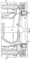
- Figure 13 illustrates a close-up sectional view of the bottom protection assembly 60.
- the bush cup assembly 65 includes two concentrically aligned brushes/brush rings 66, each of which includes a solid rubber membrane 122 embedded within each of the concentrically aligned brush rings 66.
- the bushes 66 themselves are formed from material, such as but not limited to rubber, that is both resiliently flexible as well as being able to maintain structural integrity even in high temperature environments.
- An interior, preferably fabric, liner 124 is disposed between the brushes 66 and the laser head 80, in order to protect the brushes from damage due to operation of the laser head 80.
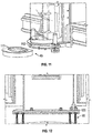
- Figure 14 shows the non-linear path 126 that light emanating from the laser head 80 must follow, in order to escape the protective enclosure of the present invention.
- the laser head 80 is much more easily accessible than known devices, and this additional functionality is shown in Figure 15 .
- the light shield 23 is movably mounted to linear guides 128, which allow the light shield 23 to be moved up or down (to a raised, or lowered, position) for the quick adjustment of, e.g., the focus of the cutting beam, or the like.
- a pair of proximity sensors 130 are therefore utilized to determine if and when the light shield is in its lowered position, and only allows operation of the laser head 80 if the sensors 130 agree that the light shield is in the proper, protective (lowered) position.
- the present invention has developed a laser cutting apparatus for the manipulation of workpieces, preferably metal workpieces.
- the present invention utilizes a protective enclosure about the laser head only, thereby leaving the majority of the apparatus open to inspection and manipulation, as necessary.
- the present invention utilizes a series of integrated safety switches, any of which can cause the operation of the laser head to be halted or prohibited, should any of these safety switches indicate an unsafe situation.
- These safety switches can of course be integrated with a machine-stop button, preferably in series, so as to make the operation of the laser head 80 as safe as possible.
Landscapes
- Engineering & Computer Science (AREA)
- Mechanical Engineering (AREA)
- Physics & Mathematics (AREA)
- Optics & Photonics (AREA)
- Plasma & Fusion (AREA)
- General Engineering & Computer Science (AREA)
- Laser Beam Processing (AREA)
Applications Claiming Priority (1)
| Application Number | Priority Date | Filing Date | Title |
|---|---|---|---|
| US15/905,957 US20180200839A1 (en) | 2016-01-12 | 2018-02-27 | Protection system for laser cutting machine |
Publications (2)
| Publication Number | Publication Date |
|---|---|
| EP3590649A2 true EP3590649A2 (fr) | 2020-01-08 |
| EP3590649A3 EP3590649A3 (fr) | 2020-06-24 |
Family
ID=66323755
Family Applications (1)
| Application Number | Title | Priority Date | Filing Date |
|---|---|---|---|
| EP19171589.5A Pending EP3590649A3 (fr) | 2018-02-27 | 2019-04-29 | Système de protection pour machine de découpe laser |
Country Status (3)
| Country | Link |
|---|---|
| EP (1) | EP3590649A3 (fr) |
| AU (4) | AU2019201925A1 (fr) |
| RU (1) | RU2727372C1 (fr) |
Cited By (10)
| Publication number | Priority date | Publication date | Assignee | Title |
|---|---|---|---|---|
| CN111230342A (zh) * | 2020-03-23 | 2020-06-05 | 安徽速达数控设备有限责任公司 | 防护装置及激光切割机 |
| CN113130964A (zh) * | 2021-03-05 | 2021-07-16 | 浙江南都电源动力股份有限公司 | 一种蝴蝶焊设备 |
| CN113941780A (zh) * | 2020-07-16 | 2022-01-18 | 大族激光科技产业集团股份有限公司 | 一种激光加工装置、激光打标设备及激光加工方法 |
| CN114161032A (zh) * | 2021-11-10 | 2022-03-11 | 王永双 | 一种龙门焊接机 |
| CN114289844A (zh) * | 2022-01-21 | 2022-04-08 | 芜湖市夯福机械模具有限公司 | 一种汽车仪表板横梁自动弧焊工作站 |
| CN114309993A (zh) * | 2022-02-21 | 2022-04-12 | 祥鸿全自动汽车检修设备(辽宁)有限公司 | 一种机械设备生产用的板材激光切割机 |
| CN118768763A (zh) * | 2024-09-10 | 2024-10-15 | 超快激光(天津)机械设备有限公司 | 一种三维五轴激光切割机 |
| CN119216818A (zh) * | 2024-11-14 | 2024-12-31 | 泰州高锐金属科技有限公司 | 一种液压板料激光切割装置 |
| CN119816395A (zh) * | 2023-02-22 | 2025-04-11 | 广东科杰技术股份有限公司 | 五轴增减材加工设备及其控制方法 |
| CN119927431A (zh) * | 2025-04-01 | 2025-05-06 | 无锡富世特新材料有限公司 | 一种复合耐磨钢板板材复合焊接装置 |
Families Citing this family (3)
| Publication number | Priority date | Publication date | Assignee | Title |
|---|---|---|---|---|
| RU202164U1 (ru) * | 2020-09-07 | 2021-02-05 | Общество с ограниченной ответственностью "СПЕЦВЕНТРЕШЕНИЕ" | Станок лазерной резки с жестким закреплением защитного кожуха |
| RU2765549C1 (ru) * | 2021-03-29 | 2022-02-01 | Федеральное государственное бюджетное образовательное учреждение высшего образования "Комсомольский-на-Амуре государственный университет" (ФГБОУ ВО "КнАГУ") | Активная автоматизированная система безопасности технологического комплекса лазерной обработки |
| CN117548847A (zh) * | 2023-11-23 | 2024-02-13 | 江苏恒轩激光智能科技有限公司 | 一种采用多层外防护移门设计的激光切割机 |
Citations (1)
| Publication number | Priority date | Publication date | Assignee | Title |
|---|---|---|---|---|
| CN1234497C (zh) * | 2000-08-31 | 2006-01-04 | 三菱电机株式会社 | 激光加工头 |
Family Cites Families (5)
| Publication number | Priority date | Publication date | Assignee | Title |
|---|---|---|---|---|
| FR2690641B1 (fr) * | 1992-04-30 | 1996-07-12 | Lectra Systemes Sa | Dispositif de securite pour machines utilisant un faisceau laser et procede de mise en óoeuvre. |
| RU2095431C1 (ru) * | 1996-03-15 | 1997-11-10 | Акционерное общество закрытого типа "Технолазер" | Установка для лазерной обработки листовых материалов |
| US6246025B1 (en) * | 1999-04-30 | 2001-06-12 | W. A. Whitney Co. | Insulated slag collection bed for a laser-equipped machine tool |
| RU2468903C1 (ru) * | 2011-05-10 | 2012-12-10 | Алексей Николаевич Коруков | Станок для лазерной резки материалов |
| HUE062022T2 (hu) * | 2016-01-12 | 2023-09-28 | Mestek Machinery Inc | Kefe-részegységgel ellátott felsõ fedeles lézervágó szerszám védõburkolat-részegységgel |
-
2019
- 2019-03-20 AU AU2019201925A patent/AU2019201925A1/en not_active Abandoned
- 2019-03-26 RU RU2019108659A patent/RU2727372C1/ru active
- 2019-04-29 EP EP19171589.5A patent/EP3590649A3/fr active Pending
-
2021
- 2021-10-29 AU AU2021258066A patent/AU2021258066A1/en not_active Abandoned
-
2023
- 2023-11-20 AU AU2023269499A patent/AU2023269499A1/en not_active Abandoned
-
2025
- 2025-10-08 AU AU2025248648A patent/AU2025248648A1/en active Pending
Patent Citations (1)
| Publication number | Priority date | Publication date | Assignee | Title |
|---|---|---|---|---|
| CN1234497C (zh) * | 2000-08-31 | 2006-01-04 | 三菱电机株式会社 | 激光加工头 |
Cited By (11)
| Publication number | Priority date | Publication date | Assignee | Title |
|---|---|---|---|---|
| CN111230342A (zh) * | 2020-03-23 | 2020-06-05 | 安徽速达数控设备有限责任公司 | 防护装置及激光切割机 |
| CN113941780A (zh) * | 2020-07-16 | 2022-01-18 | 大族激光科技产业集团股份有限公司 | 一种激光加工装置、激光打标设备及激光加工方法 |
| CN113130964A (zh) * | 2021-03-05 | 2021-07-16 | 浙江南都电源动力股份有限公司 | 一种蝴蝶焊设备 |
| CN114161032A (zh) * | 2021-11-10 | 2022-03-11 | 王永双 | 一种龙门焊接机 |
| CN114289844A (zh) * | 2022-01-21 | 2022-04-08 | 芜湖市夯福机械模具有限公司 | 一种汽车仪表板横梁自动弧焊工作站 |
| CN114309993A (zh) * | 2022-02-21 | 2022-04-12 | 祥鸿全自动汽车检修设备(辽宁)有限公司 | 一种机械设备生产用的板材激光切割机 |
| CN114309993B (zh) * | 2022-02-21 | 2024-04-30 | 祥鸿全自动汽车检修设备(辽宁)有限公司 | 一种机械设备生产用的板材激光切割机 |
| CN119816395A (zh) * | 2023-02-22 | 2025-04-11 | 广东科杰技术股份有限公司 | 五轴增减材加工设备及其控制方法 |
| CN118768763A (zh) * | 2024-09-10 | 2024-10-15 | 超快激光(天津)机械设备有限公司 | 一种三维五轴激光切割机 |
| CN119216818A (zh) * | 2024-11-14 | 2024-12-31 | 泰州高锐金属科技有限公司 | 一种液压板料激光切割装置 |
| CN119927431A (zh) * | 2025-04-01 | 2025-05-06 | 无锡富世特新材料有限公司 | 一种复合耐磨钢板板材复合焊接装置 |
Also Published As
| Publication number | Publication date |
|---|---|
| RU2727372C1 (ru) | 2020-07-21 |
| AU2019201925A1 (en) | 2019-09-19 |
| AU2023269499A1 (en) | 2023-12-14 |
| AU2025248648A1 (en) | 2025-10-30 |
| AU2021258066A1 (en) | 2021-11-25 |
| EP3590649A3 (fr) | 2020-06-24 |
Similar Documents
| Publication | Publication Date | Title |
|---|---|---|
| AU2019222800B2 (en) | Protection system for laser cutting machine | |
| AU2023269499A1 (en) | Protection System for Laser Cutting Machine | |
| US20180200839A1 (en) | Protection system for laser cutting machine | |
| US12491577B2 (en) | Protection system for laser cutting machine | |
| AU2024202657B2 (en) | Protection System for Laser Cutting Machine | |
| KR102123133B1 (ko) | 작업편을 가공하기 위한 기계 공구 및 방법 | |
| CN210817963U (zh) | 激光焊接设备 | |
| US9744622B2 (en) | Moving a laser processing head relative to a clamping claw | |
| CA3037420C (fr) | Systeme de protection pour machine de taille au laser | |
| CN109877476A (zh) | 用于激光切割机的防护系统 | |
| US20250153274A1 (en) | Protection system for laser cutting machine | |
| KR102344466B1 (ko) | 용접작업용 센서 커버 자동개폐 장치 |
Legal Events
| Date | Code | Title | Description |
|---|---|---|---|
| PUAI | Public reference made under article 153(3) epc to a published international application that has entered the european phase |
Free format text: ORIGINAL CODE: 0009012 |
|
| STAA | Information on the status of an ep patent application or granted ep patent |
Free format text: STATUS: THE APPLICATION HAS BEEN PUBLISHED |
|
| AK | Designated contracting states |
Kind code of ref document: A2 Designated state(s): AL AT BE BG CH CY CZ DE DK EE ES FI FR GB GR HR HU IE IS IT LI LT LU LV MC MK MT NL NO PL PT RO RS SE SI SK SM TR |
|
| AX | Request for extension of the european patent |
Extension state: BA ME |
|
| PUAL | Search report despatched |
Free format text: ORIGINAL CODE: 0009013 |
|
| AK | Designated contracting states |
Kind code of ref document: A3 Designated state(s): AL AT BE BG CH CY CZ DE DK EE ES FI FR GB GR HR HU IE IS IT LI LT LU LV MC MK MT NL NO PL PT RO RS SE SI SK SM TR |
|
| AX | Request for extension of the european patent |
Extension state: BA ME |
|
| RIC1 | Information provided on ipc code assigned before grant |
Ipc: B23K 26/70 20140101AFI20200518BHEP Ipc: B23K 26/38 20140101ALI20200518BHEP |
|
| STAA | Information on the status of an ep patent application or granted ep patent |
Free format text: STATUS: REQUEST FOR EXAMINATION WAS MADE |
|
| 17P | Request for examination filed |
Effective date: 20201223 |
|
| RBV | Designated contracting states (corrected) |
Designated state(s): AL AT BE BG CH CY CZ DE DK EE ES FI FR GB GR HR HU IE IS IT LI LT LU LV MC MK MT NL NO PL PT RO RS SE SI SK SM TR |
|
| P01 | Opt-out of the competence of the unified patent court (upc) registered |
Effective date: 20230529 |
|
| STAA | Information on the status of an ep patent application or granted ep patent |
Free format text: STATUS: EXAMINATION IS IN PROGRESS |
|
| 17Q | First examination report despatched |
Effective date: 20231006 |