EP3590708B1 - Laminated glazing - Google Patents
Laminated glazing Download PDFInfo
- Publication number
- EP3590708B1 EP3590708B1 EP19188149.9A EP19188149A EP3590708B1 EP 3590708 B1 EP3590708 B1 EP 3590708B1 EP 19188149 A EP19188149 A EP 19188149A EP 3590708 B1 EP3590708 B1 EP 3590708B1
- Authority
- EP
- European Patent Office
- Prior art keywords
- glass sheet
- hole
- conducting wire
- glazing unit
- laminated glazing
- Prior art date
- Legal status (The legal status is an assumption and is not a legal conclusion. Google has not performed a legal analysis and makes no representation as to the accuracy of the status listed.)
- Active
Links
Images

Classifications
-
- B—PERFORMING OPERATIONS; TRANSPORTING
- B32—LAYERED PRODUCTS
- B32B—LAYERED PRODUCTS, i.e. PRODUCTS BUILT-UP OF STRATA OF FLAT OR NON-FLAT, e.g. CELLULAR OR HONEYCOMB, FORM
- B32B17/00—Layered products essentially comprising sheet glass, or glass, slag, or like fibres
- B32B17/06—Layered products essentially comprising sheet glass, or glass, slag, or like fibres comprising glass as the main or only constituent of a layer, next to another layer of a specific material
- B32B17/10—Layered products essentially comprising sheet glass, or glass, slag, or like fibres comprising glass as the main or only constituent of a layer, next to another layer of a specific material of synthetic resin
- B32B17/10005—Layered products essentially comprising sheet glass, or glass, slag, or like fibres comprising glass as the main or only constituent of a layer, next to another layer of a specific material of synthetic resin laminated safety glass or glazing
- B32B17/10009—Layered products essentially comprising sheet glass, or glass, slag, or like fibres comprising glass as the main or only constituent of a layer, next to another layer of a specific material of synthetic resin laminated safety glass or glazing characterized by the number, the constitution or treatment of glass sheets
- B32B17/10036—Layered products essentially comprising sheet glass, or glass, slag, or like fibres comprising glass as the main or only constituent of a layer, next to another layer of a specific material of synthetic resin laminated safety glass or glazing characterized by the number, the constitution or treatment of glass sheets comprising two outer glass sheets
-
- B—PERFORMING OPERATIONS; TRANSPORTING
- B32—LAYERED PRODUCTS
- B32B—LAYERED PRODUCTS, i.e. PRODUCTS BUILT-UP OF STRATA OF FLAT OR NON-FLAT, e.g. CELLULAR OR HONEYCOMB, FORM
- B32B17/00—Layered products essentially comprising sheet glass, or glass, slag, or like fibres
- B32B17/06—Layered products essentially comprising sheet glass, or glass, slag, or like fibres comprising glass as the main or only constituent of a layer, next to another layer of a specific material
- B32B17/10—Layered products essentially comprising sheet glass, or glass, slag, or like fibres comprising glass as the main or only constituent of a layer, next to another layer of a specific material of synthetic resin
- B32B17/10005—Layered products essentially comprising sheet glass, or glass, slag, or like fibres comprising glass as the main or only constituent of a layer, next to another layer of a specific material of synthetic resin laminated safety glass or glazing
- B32B17/10165—Functional features of the laminated safety glass or glazing
- B32B17/10293—Edge features, e.g. inserts or holes
-
- B—PERFORMING OPERATIONS; TRANSPORTING
- B32—LAYERED PRODUCTS
- B32B—LAYERED PRODUCTS, i.e. PRODUCTS BUILT-UP OF STRATA OF FLAT OR NON-FLAT, e.g. CELLULAR OR HONEYCOMB, FORM
- B32B17/00—Layered products essentially comprising sheet glass, or glass, slag, or like fibres
- B32B17/06—Layered products essentially comprising sheet glass, or glass, slag, or like fibres comprising glass as the main or only constituent of a layer, next to another layer of a specific material
- B32B17/10—Layered products essentially comprising sheet glass, or glass, slag, or like fibres comprising glass as the main or only constituent of a layer, next to another layer of a specific material of synthetic resin
- B32B17/10005—Layered products essentially comprising sheet glass, or glass, slag, or like fibres comprising glass as the main or only constituent of a layer, next to another layer of a specific material of synthetic resin laminated safety glass or glazing
- B32B17/10165—Functional features of the laminated safety glass or glazing
- B32B17/10376—Laminated safety glass or glazing containing metal wires
-
- B—PERFORMING OPERATIONS; TRANSPORTING
- B32—LAYERED PRODUCTS
- B32B—LAYERED PRODUCTS, i.e. PRODUCTS BUILT-UP OF STRATA OF FLAT OR NON-FLAT, e.g. CELLULAR OR HONEYCOMB, FORM
- B32B17/00—Layered products essentially comprising sheet glass, or glass, slag, or like fibres
- B32B17/06—Layered products essentially comprising sheet glass, or glass, slag, or like fibres comprising glass as the main or only constituent of a layer, next to another layer of a specific material
- B32B17/10—Layered products essentially comprising sheet glass, or glass, slag, or like fibres comprising glass as the main or only constituent of a layer, next to another layer of a specific material of synthetic resin
- B32B17/10005—Layered products essentially comprising sheet glass, or glass, slag, or like fibres comprising glass as the main or only constituent of a layer, next to another layer of a specific material of synthetic resin laminated safety glass or glazing
- B32B17/1055—Layered products essentially comprising sheet glass, or glass, slag, or like fibres comprising glass as the main or only constituent of a layer, next to another layer of a specific material of synthetic resin laminated safety glass or glazing characterized by the resin layer, i.e. interlayer
- B32B17/10761—Layered products essentially comprising sheet glass, or glass, slag, or like fibres comprising glass as the main or only constituent of a layer, next to another layer of a specific material of synthetic resin laminated safety glass or glazing characterized by the resin layer, i.e. interlayer containing vinyl acetal
-
- B—PERFORMING OPERATIONS; TRANSPORTING
- B32—LAYERED PRODUCTS
- B32B—LAYERED PRODUCTS, i.e. PRODUCTS BUILT-UP OF STRATA OF FLAT OR NON-FLAT, e.g. CELLULAR OR HONEYCOMB, FORM
- B32B3/00—Layered products comprising a layer with external or internal discontinuities or unevennesses, or a layer of non-planar shape; Layered products comprising a layer having particular features of form
- B32B3/26—Layered products comprising a layer with external or internal discontinuities or unevennesses, or a layer of non-planar shape; Layered products comprising a layer having particular features of form characterised by a particular shape of the outline of the cross-section of a continuous layer; characterised by a layer with cavities or internal voids ; characterised by an apertured layer
- B32B3/266—Layered products comprising a layer with external or internal discontinuities or unevennesses, or a layer of non-planar shape; Layered products comprising a layer having particular features of form characterised by a particular shape of the outline of the cross-section of a continuous layer; characterised by a layer with cavities or internal voids ; characterised by an apertured layer characterised by an apertured layer, the apertures going through the whole thickness of the layer, e.g. expanded metal, perforated layer, slit layer regular cells B32B3/12
-
- B—PERFORMING OPERATIONS; TRANSPORTING
- B32—LAYERED PRODUCTS
- B32B—LAYERED PRODUCTS, i.e. PRODUCTS BUILT-UP OF STRATA OF FLAT OR NON-FLAT, e.g. CELLULAR OR HONEYCOMB, FORM
- B32B37/00—Methods or apparatus for laminating, e.g. by curing or by ultrasonic bonding
- B32B37/10—Methods or apparatus for laminating, e.g. by curing or by ultrasonic bonding characterised by the pressing technique, e.g. using action of vacuum or fluid pressure
- B32B37/1018—Methods or apparatus for laminating, e.g. by curing or by ultrasonic bonding characterised by the pressing technique, e.g. using action of vacuum or fluid pressure using only vacuum
-
- B—PERFORMING OPERATIONS; TRANSPORTING
- B32—LAYERED PRODUCTS
- B32B—LAYERED PRODUCTS, i.e. PRODUCTS BUILT-UP OF STRATA OF FLAT OR NON-FLAT, e.g. CELLULAR OR HONEYCOMB, FORM
- B32B37/00—Methods or apparatus for laminating, e.g. by curing or by ultrasonic bonding
- B32B37/12—Methods or apparatus for laminating, e.g. by curing or by ultrasonic bonding characterised by using adhesives
- B32B37/1207—Heat-activated adhesive
-
- B—PERFORMING OPERATIONS; TRANSPORTING
- B32—LAYERED PRODUCTS
- B32B—LAYERED PRODUCTS, i.e. PRODUCTS BUILT-UP OF STRATA OF FLAT OR NON-FLAT, e.g. CELLULAR OR HONEYCOMB, FORM
- B32B37/00—Methods or apparatus for laminating, e.g. by curing or by ultrasonic bonding
- B32B37/14—Methods or apparatus for laminating, e.g. by curing or by ultrasonic bonding characterised by the properties of the layers
- B32B37/16—Methods or apparatus for laminating, e.g. by curing or by ultrasonic bonding characterised by the properties of the layers with all layers existing as coherent layers before laminating
-
- B—PERFORMING OPERATIONS; TRANSPORTING
- B32—LAYERED PRODUCTS
- B32B—LAYERED PRODUCTS, i.e. PRODUCTS BUILT-UP OF STRATA OF FLAT OR NON-FLAT, e.g. CELLULAR OR HONEYCOMB, FORM
- B32B2307/00—Properties of the layers or laminate
- B32B2307/20—Properties of the layers or laminate having particular electrical or magnetic properties, e.g. piezoelectric
- B32B2307/202—Conductive
-
- B—PERFORMING OPERATIONS; TRANSPORTING
- B32—LAYERED PRODUCTS
- B32B—LAYERED PRODUCTS, i.e. PRODUCTS BUILT-UP OF STRATA OF FLAT OR NON-FLAT, e.g. CELLULAR OR HONEYCOMB, FORM
- B32B2307/00—Properties of the layers or laminate
- B32B2307/40—Properties of the layers or laminate having particular optical properties
- B32B2307/412—Transparent
-
- B—PERFORMING OPERATIONS; TRANSPORTING
- B32—LAYERED PRODUCTS
- B32B—LAYERED PRODUCTS, i.e. PRODUCTS BUILT-UP OF STRATA OF FLAT OR NON-FLAT, e.g. CELLULAR OR HONEYCOMB, FORM
- B32B2398/00—Unspecified macromolecular compounds
- B32B2398/20—Thermoplastics
-
- B—PERFORMING OPERATIONS; TRANSPORTING
- B32—LAYERED PRODUCTS
- B32B—LAYERED PRODUCTS, i.e. PRODUCTS BUILT-UP OF STRATA OF FLAT OR NON-FLAT, e.g. CELLULAR OR HONEYCOMB, FORM
- B32B2605/00—Vehicles
- B32B2605/006—Transparent parts other than made from inorganic glass, e.g. polycarbonate glazings
-
- B—PERFORMING OPERATIONS; TRANSPORTING
- B60—VEHICLES IN GENERAL
- B60J—WINDOWS, WINDSCREENS, NON-FIXED ROOFS, DOORS, OR SIMILAR DEVICES FOR VEHICLES; REMOVABLE EXTERNAL PROTECTIVE COVERINGS SPECIALLY ADAPTED FOR VEHICLES
- B60J1/00—Windows; Windscreens; Accessories therefor
-
- H—ELECTRICITY
- H01—ELECTRIC ELEMENTS
- H01Q—ANTENNAS, i.e. RADIO AERIALS
- H01Q1/00—Details of, or arrangements associated with, antennas
- H01Q1/12—Supports; Mounting means
- H01Q1/1271—Supports; Mounting means for mounting on windscreens
-
- H—ELECTRICITY
- H10—SEMICONDUCTOR DEVICES; ELECTRIC SOLID-STATE DEVICES NOT OTHERWISE PROVIDED FOR
- H10F—INORGANIC SEMICONDUCTOR DEVICES SENSITIVE TO INFRARED RADIATION, LIGHT, ELECTROMAGNETIC RADIATION OF SHORTER WAVELENGTH OR CORPUSCULAR RADIATION
- H10F77/00—Constructional details of devices covered by this subclass
- H10F77/93—Interconnections
- H10F77/933—Interconnections for devices having potential barriers
- H10F77/935—Interconnections for devices having potential barriers for photovoltaic devices or modules
- H10F77/939—Output lead wires or elements
-
- Y—GENERAL TAGGING OF NEW TECHNOLOGICAL DEVELOPMENTS; GENERAL TAGGING OF CROSS-SECTIONAL TECHNOLOGIES SPANNING OVER SEVERAL SECTIONS OF THE IPC; TECHNICAL SUBJECTS COVERED BY FORMER USPC CROSS-REFERENCE ART COLLECTIONS [XRACs] AND DIGESTS
- Y10—TECHNICAL SUBJECTS COVERED BY FORMER USPC
- Y10T—TECHNICAL SUBJECTS COVERED BY FORMER US CLASSIFICATION
- Y10T29/00—Metal working
- Y10T29/49—Method of mechanical manufacture
- Y10T29/49002—Electrical device making
- Y10T29/49117—Conductor or circuit manufacturing
- Y10T29/49169—Assembling electrical component directly to terminal or elongated conductor
Definitions
- the invention relates to laminated glazing intended to bring conductive wires to an accessory such as, for example, a camera or a rain sensor.
- a windshield is usually made of two sheets of glass between which is placed a thermoplastic polymer interlayer.
- the surfaces of the glass sheets of such a laminated glazing are numbered from 1 to 4, starting from the external surface of the glazing intended to face the outside of the vehicle and ending with the external surface of the glazing intended to face the inside of the vehicle.
- the power supply for electrical accessories consisting of conductive wires, is generally fixed to face 4 of the windshield.
- the conductive wires are hidden from view inside the passenger compartment by a trunking fixed to the glass, the trunking covering the conductive wires.
- the conductive wires are hidden from view outside the passenger compartment by a strip of black enamel placed for example on face 2 or face 4 of the windshield.
- the wires are not properly positioned in the cable duct or protrude beyond the enamel strip.
- the cable duct takes up space on the windshield and obscures part of the driver's view, especially on panoramic windshields.
- the cable duct can be a source of noise at certain speeds due to windshield vibrations.
- FR 2 348 616 A2 describes a laminated glazing comprising a first and a second glass sheet, the first glass sheet being provided with a first through hole, an interlayer film of thermoplastic material disposed between the first and second glass sheets, and a conductive wire embedded in the interlayer film, one end of the conductive wire exiting the laminated glazing through the first through hole in the first glass sheet.
- the interlayer film when the conductive wire is arranged between the interlayer film and the second glass sheet, the interlayer film is provided with a through hole allowing the conductive wire to pass through the interlayer film and through the first glass sheet, the through hole of the interlayer film having a size between a minimum value just allowing the conductive wire to pass and a maximum value for which the hole substantially coincides with the first hole of the first glass sheet.
- the second glass sheet is also provided with a through hole, the first through hole of the first glass sheet and the through hole of the second glass sheet having substantially the same size and facing each other, and the interlayer film is also provided with a through hole coinciding with the through holes of the first and second glass sheets.
- each conductive wire exits the laminated glazing through the edge of the laminated glazing or through a second through hole in the first sheet of glass located at the edge of the glazing or through a through hole in the second sheet of glass located at the edge of the glazing.
- the first glass sheet is provided with several first through holes arranged close to each other.
- the laminated glazing comprises several conductive wires, one end of each conductive wire exiting the laminated glazing through the first through hole(s) of the first sheet of glass.
- each through hole has a size between 3 and 80 mm.
- the laminated glazing further comprises at least one strip of opaque enamel coinciding with the conductive wire(s), hiding the conductive wire(s) from view from the outside and/or the inside.
- the laminated glazing further comprises an accessory fixed to the laminated glazing near or at the level of the first through hole(s), the accessory being connected to the end of the conductive wire(s) exiting the laminated glazing through the first through hole(s) of the first sheet of glass.
- the accessory is a rain or humidity sensor, a light sensor, a camera, an antenna, a lighting device, a fan or even a GPS positioning device.
- the accessory may be fixed on or near the edges of the first through hole(s) of the first glass sheet or housed inside a through hole of the first glass sheet and fixed on the second glass sheet.
- the conductive wire is a coaxial cable, preferably shielded.
- the "size" of a hole means the largest dimension of the hole, namely the diameter when the hole is circular.
- the invention relates to a laminated glazing unit comprising a first and a second glass sheet, as well as an interlayer film made of thermoplastic polymer arranged between the two glass sheets.
- the first glass sheet is provided with a first through hole.
- the laminated glazing unit also comprises at least one conductive wire embedded in the interlayer film or arranged between the interlayer film and the first glass sheet or arranged between the interlayer film and the second glass sheet, one end of the conductive wire exiting the laminated glazing unit through the first through hole in the first glass sheet.
- the conductive wire(s) are arranged between the two sheets of glass by being embedded in the thermoplastic polymer film or by being arranged between the thermoplastic polymer film and one of the sheets of glass, which guarantees quality positioning of the conductive wires and greater ease of transport without damaging the conductive wires.
- the trunking is no longer necessary because the conductive wires can exit the glazing at the very location where the accessory to be connected is positioned. As a result, the field of vision is improved and there is no longer any noise generated by the trunking while the vehicle is moving.
- FIG. 1 represents a sectional view of laminated glazing according to the invention.
- the laminated glazing comprises a first glass sheet 1, a second glass sheet 2 and an interlayer film 3 made of thermoplastic polymer, arranged between the two glass sheets.
- the interlayer film is for example a PVB film, standard or with acoustic damping properties.
- the first glass sheet comprises a first through hole 4.
- the first glass sheet 1 can be positioned on the inner side as well as on the outer side of the vehicle, depending on the applications.
- the interlayer film can comprise a through hole coinciding with the first through hole 4 of the first glass sheet, as shown in the Figure 4 .
- the laminated glazing also comprises at least one conductive wire 5 which is embedded in the interlayer film 3 or which is arranged between the interlayer film 3 and the first glass sheet 1, or which is arranged between the interlayer film 3 and the second glass sheet 2. This provides it with protection which is integrated into the laminated glazing.
- the interlayer film 3 may be provided with a through hole which coincides with the first hole 4 of the first glass sheet 1, that is to say which has substantially the same size and which is opposite, to allow the passage of the conductive wire 5 through the interlayer film 3 and through the first glass sheet 1.
- the interlayer film 3 is pierced with a through hole which is as small as possible to ensure just the passage of the conductive wire 5.
- the through hole in the interlayer film 3 may also have all possible sizes between these two extreme values.
- the maximum size of the through hole of the interlayer film is at most 10 mm larger than the size of the through hole of the glass sheet.
- the interlayer film does not have any through holes, which allows the glazing to better resist impacts.
- the conductive wire 5 has an end 50 which is intended to be connected to an accessory 6, for example an electrical accessory, via a connector (7 on the figures 2 , 4 and 5 ).
- the other end 51 of the conductive wire 5 is intended to be connected to a power supply and/or an electrical device on the vehicle, via a connector (9 on the Figures 4 and 5 ).
- One end 50 of the conductive wire 5 exits the laminated glazing through the first through hole 4.
- the first through hole 4 is for example circular, for ease of manufacture. It must be as small as possible to allow the laminated glazing to comply with the R43 standard and large enough to allow the wire to pass through conductor and connector, through. Thus, preferably, the first through hole 4 has a size between 3 and 80 mm.
- the conductive wire(s) 5 are coated in a plastic film forming a thin and flexible sheet.
- the conductive wire(s) 5 are coated in a plastic film forming a sheet.
- the plastic film can be transparent (which allows for a very discreet product), black (which avoids adding black enamel to the glass to mask the conductive wires), or even colored (which can improve the appearance of the finished product, once integrated into a glazing).
- the use of such a sheet also provides ease of handling during assembly.
- the sheet is equipped with connectors at each of its ends before assembly of the glazing.
- the sheet can be coated with PVB or an adhesive to allow its adhesion to the first glass sheet.
- the sheet must also be thin enough to avoid permanently bending the glass during assembly and thus avoid any breakage of the glass at the edge of the hole(s) through which the sheet exits.
- the glass preferably has edge constraints on the periphery of the exit holes of the ends of the conductive wires.
- the accessory 6 to which the conductive wire(s) 5 is intended to be connected can be fixed to the laminated glazing, as shown in the Figure 1 , or near the laminated glazing, for example on a rearview mirror support.
- the accessory 6 is for example a rain or humidity sensor, a brightness sensor, a camera, an antenna, a lighting device, a fan or even a GPS positioning device.
- the conductive wire 5 allows the electrical supply of the accessory 6 and/or the supply of information transmitted by the accessory 6 to the electrical device of the vehicle.
- the conductive wire 5 is for example made of copper.
- the conductive wire(s) 5 may be coaxial cables, preferably shielded.
- one or more 5 conductive wires are required.
- FIGS. 2a, 2b, 2c are a detailed view, according to three respective embodiments, of the laminated glazing according to the invention with several conductive wires.
- the first glass sheet 1 comprises a single first through hole 4, of circular shape, through which the ends 50 of the conductive wires 5 intended to be connected to an accessory exit.
- the first glass sheet 1 comprises a single first through hole 4, in the form of a slot, through which the ends 50 of the conductive wires 5 intended to be connected to an accessory exit.
- the first glass sheet 1 comprises three first through holes 4, of circular shape, through each of which emerges the end 50 of a conductive wire 5 intended to be connected to an accessory.
- Circular through holes can be made with a hole saw. Slotted through holes can be made by water jet drilling or by machining with a diamond cutter.
- the end 50 of the conductive wire(s) 5 intended to be connected to the accessory 6 can be inserted into a connector 7, as shown in the Figures 2a to 2c , which facilitates connection to the accessory 6, in particular when this takes place well after the manufacture of the laminated glazing.
- FIG. 3 is a detailed view of the edge of the laminated glazing according to one embodiment of the invention.
- the first glass sheet 1 may comprise a second through hole 8 at the edge of the glazing.
- the second through hole 8 allows the exit of the other end 51 of the conductive wire 5 for connection to a power supply and/or an electrical device on the vehicle. This other end 51 may be inserted into a connector 9 ( Figures 4 and 5 ) for ease of subsequent connection to the vehicle.
- the second through hole 8 of the first glass sheet 1 may be made on the edge of the first glass sheet 1, for example in the form of a notch, as shown in the Figure 3 , or near the edge of the first sheet of glass 1.
- the end 51 of the conductive wire 5 exits the laminated glazing through the edge of the laminated glazing, as shown in the Figure 1 .
- the laminated glazing further comprises at least one opaque enamel strip coinciding with the conductive wire(s), hiding the conductive wire(s) from view from the outside and/or the inside of the vehicle.
- the conductive wires embedded in the interlayer film can be very thin (a few tens to a few hundred microns) and the sheet has a thin width (a few millimeters to around fifteen millimeters)
- the enamel strip is much thinner than when a trunking is used, and the enamel strip is not three-dimensional like the trunking, which makes it possible to significantly improve the field of vision and visual comfort.
- the laminated glazing may also comprise an accessory 6 fixed to the laminated glazing.
- the accessory 6 may be fixed to the edges of the first through hole(s) 4 of the first glass sheet 1, for example by snap-fastening or gluing, or near the first through hole(s) 4 of the first glass sheet 1, for example by gluing.
- the accessory may also be housed inside the through hole 4 of the first glass sheet 1 and be fixed, for example by gluing, to the second glass sheet 2, on face 2 or 3 of the laminated glazing depending on the positioning of the first and second glass sheets in the laminated glazing.
- the second glass sheet may also comprise a through hole (15, Figure 5 ).
- the first through hole 4 of the first glass sheet 1 and the through hole 15 of the second glass sheet 2 are preferably substantially the same size and face each other.
- the interlayer film is then also provided with a through hole which coincides with the first holes 4, 15 of the first and second glass sheets 1, 2, as shown in the Figure 5 , that is to say which has substantially the same size and which is opposite the through holes 4 and 15.
- the maximum size of the through hole of the interlayer film is at most 10 mm larger than the size of the through holes of the two sheets of glass.
- the second glass sheet 2 may also comprise a through hole at the edge of the glazing, which may be made on the edge of the second glass sheet 2, for example in the form of a notch, or close to the edge of the second glass sheet 2.
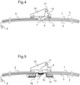
- FIGS. 4 and 5 are sectional views, according to two respective embodiments, of a laminated glazing according to the invention with an antenna accessory mounted on the glazing.
- An antenna base 10 is fixed to the laminated glazing by fixing means 13, for example glue, via support means 12.
- the antenna base 10 comprises a connector 11 to which the conductive wire 5 is connected via the connector 7.
- the first glass sheet 1 faces the outside of the vehicle. Watertightness is ensured by the fixing means 13 which completely surround the through holes.
- the second glass sheet also includes a through hole 15.
- the through hole 15 coincides with the first through hole 4 and additionally comprises a notch 16 to facilitate the passage of the conductive wire 5.
Landscapes
- Engineering & Computer Science (AREA)
- Mechanical Engineering (AREA)
- Physics & Mathematics (AREA)
- Fluid Mechanics (AREA)
- Joining Of Glass To Other Materials (AREA)
- Laminated Bodies (AREA)
- Architecture (AREA)
- Civil Engineering (AREA)
- Structural Engineering (AREA)
Description
L'invention concerne un vitrage feuilleté destiné à amener des fils conducteurs jusqu'à un accessoire tel que par exemple une caméra ou un capteur de pluie.The invention relates to laminated glazing intended to bring conductive wires to an accessory such as, for example, a camera or a rain sensor.
Il est connu de disposer des accessoires électriques tels qu'une caméra ou un capteur de pluie sur un pare-brise de véhicule automobile à proximité du rétroviseur. Un pare-brise est habituellement constitué de deux feuilles de verre entre lesquelles est disposé un intercalaire en polymère thermoplastique. On numérote les surfaces des feuilles de verre d'un tel vitrage feuilleté de 1 à 4 en partant de la surface externe du vitrage destinée à être tournée vers l'extérieur du véhicule et en finissant par la surface externe du vitrage destinée à être tournée vers l'intérieur du véhicule.It is known to have electrical accessories such as a camera or a rain sensor on a motor vehicle windshield near the rearview mirror. A windshield is usually made of two sheets of glass between which is placed a thermoplastic polymer interlayer. The surfaces of the glass sheets of such a laminated glazing are numbered from 1 to 4, starting from the external surface of the glazing intended to face the outside of the vehicle and ending with the external surface of the glazing intended to face the inside of the vehicle.
L'alimentation électrique des accessoires électriques, constituée de fils conducteurs, est en général fixée sur la face 4 du pare-brise. Les fils conducteurs sont cachés à la vue à l'intérieur de l'habitacle par une goulotte fixée sur le vitrage, la goulotte recouvrant les fils conducteurs. Les fils conducteurs sont cachés à la vue à l'extérieur de l'habitacle par une bande d'émail noir déposée par exemple en face 2 ou en face 4 du pare-brise.The power supply for electrical accessories, consisting of conductive wires, is generally fixed to
Toutefois, il arrive souvent que les fils ne soient pas bien positionnés dans la goulotte ou dépassent de la bande d'émail. De plus, la goulotte prend de la place sur le pare-brise et cache une partie de la vue au conducteur, en particulier sur des pare-brise panoramiques. De plus, la goulotte peut être source de bruit à certaines vitesses du fait des vibrations du pare-brise.However, it often happens that the wires are not properly positioned in the cable duct or protrude beyond the enamel strip. In addition, the cable duct takes up space on the windshield and obscures part of the driver's view, especially on panoramic windshields. In addition, the cable duct can be a source of noise at certain speeds due to windshield vibrations.
Il y a donc un besoin pour un vitrage feuilleté permettant l'amenée de fils conducteurs, qui garantisse une qualité de positionnement des fils conducteurs, qui permette d'avoir un champ de vision le plus grand possible et qui pallie au problème de bruit de la goulotte.There is therefore a need for laminated glazing that allows the supply of conductive wires, which guarantees quality positioning of the conductive wires, which allows for the largest possible field of vision and which overcomes the problem of noise from the trunking.
Pour cela, l'invention propose un vitrage feuilleté destiné à être monté sur un véhicule automobile, comprenant:
- une première et une deuxième feuilles de verre, la première feuille de verre étant munie d'un premier trou traversant,
- un film intercalaire en polymère thermoplastique disposé entre les première et deuxième feuilles de verre,
- au moins un fil conducteur noyé dans le film intercalaire ou disposé entre le film intercalaire et la première feuille de verre ou disposé entre le film intercalaire et la deuxième feuille de verre, une extrémité de chaque fil conducteur sortant du vitrage feuilleté par le premier trou traversant de la première feuille de verre, et dans lequel le ou les fils conducteurs sont enrobés dans un film plastique formant une nappe, le film plastique formant la nappe pouvant notamment être transparent ou noir ou de couleur, la nappe étant équipée de connecteurs à chacune de ses extrémités.
- a first and a second glass sheet, the first glass sheet being provided with a first through hole,
- a thermoplastic polymer interlayer film disposed between the first and second glass sheets,
- at least one conductive wire embedded in the interlayer film or arranged between the interlayer film and the first glass sheet or arranged between the interlayer film and the second glass sheet, one end of each conductive wire exiting the laminated glazing through the first through-hole of the first glass sheet, and in which the conductive wire(s) are coated in a plastic film forming a sheet, the plastic film forming the sheet being able in particular to be transparent or black or colored, the sheet being equipped with connectors at each of its ends.
Selon une autre particularité, lorsque le fil conducteur est disposé entre le film intercalaire et la deuxième feuille de verre, le film intercalaire est muni d'un trou traversant permettant le passage du fil conducteur à travers le film intercalaire et à travers la première feuille de verre, le trou traversant du film intercalaire ayant une taille comprise entre une valeur minimale permettant juste le passage du fil conducteur et une valeur maximale pour laquelle le trou coïncide sensiblement avec le premier trou de la première feuille de verre.According to another feature, when the conductive wire is arranged between the interlayer film and the second glass sheet, the interlayer film is provided with a through hole allowing the conductive wire to pass through the interlayer film and through the first glass sheet, the through hole of the interlayer film having a size between a minimum value just allowing the conductive wire to pass and a maximum value for which the hole substantially coincides with the first hole of the first glass sheet.
Selon une autre particularité, la deuxième feuille de verre est également munie d'un trou traversant, le premier trou traversant de la première feuille de verre et le trou traversant de la deuxième feuille de verre ayant sensiblement la même taille et se faisant face, et le film intercalaire est également muni d'un trou traversant coïncidant avec les trous traversants des première et deuxième feuilles de verre.According to another feature, the second glass sheet is also provided with a through hole, the first through hole of the first glass sheet and the through hole of the second glass sheet having substantially the same size and facing each other, and the interlayer film is also provided with a through hole coinciding with the through holes of the first and second glass sheets.
Selon une autre particularité, l'autre extrémité de chaque fil conducteur sort du vitrage feuilleté par la tranche du vitrage feuilleté ou par un deuxième trou traversant de la première feuille de verre situé en bord de vitrage ou par un trou traversant de la deuxième feuille de verre situé en bord de vitrage.According to another feature, the other end of each conductive wire exits the laminated glazing through the edge of the laminated glazing or through a second through hole in the first sheet of glass located at the edge of the glazing or through a through hole in the second sheet of glass located at the edge of the glazing.
Selon une autre particularité, la première feuille de verre est munie de plusieurs premiers trous traversants disposés à proximité les uns des autres.According to another feature, the first glass sheet is provided with several first through holes arranged close to each other.
Selon une autre particularité, le vitrage feuilleté comprend plusieurs fils conducteurs, une extrémité de chaque fil conducteur sortant du vitrage feuilleté par le ou les premiers trous traversants de la première feuille de verre.According to another feature, the laminated glazing comprises several conductive wires, one end of each conductive wire exiting the laminated glazing through the first through hole(s) of the first sheet of glass.
Selon une autre particularité, chaque trou traversant a une taille comprise entre 3 et 80 mm.According to another peculiarity, each through hole has a size between 3 and 80 mm.
Selon une autre particularité, le vitrage feuilleté comprend en outre au moins une bande d'émail opaque coïncidant avec le ou les fils conducteurs, cachant à la vue le ou les fils conducteurs depuis l'extérieur et/ou l'intérieur.According to another feature, the laminated glazing further comprises at least one strip of opaque enamel coinciding with the conductive wire(s), hiding the conductive wire(s) from view from the outside and/or the inside.
Selon une autre particularité, le vitrage feuilleté comprend en outre un accessoire fixé sur le vitrage feuilleté à proximité ou au niveau du ou des premiers trous traversants, l'accessoire étant connecté à l'extrémité du ou des fils conducteurs sortant du vitrage feuilleté par le ou les premiers trous traversants de la première feuille de verre.According to another feature, the laminated glazing further comprises an accessory fixed to the laminated glazing near or at the level of the first through hole(s), the accessory being connected to the end of the conductive wire(s) exiting the laminated glazing through the first through hole(s) of the first sheet of glass.
Selon une autre particularité, l'accessoire est un capteur de pluie ou d'humidité, un capteur de luminosité, une caméra, une antenne, un dispositif d'éclairage, un ventilateur ou encore un dispositif de positionnement par GPS.According to another feature, the accessory is a rain or humidity sensor, a light sensor, a camera, an antenna, a lighting device, a fan or even a GPS positioning device.
Selon une autre particularité, l'accessoire peut être fixé sur les ou à proximité des bords du ou des premiers trous traversants de la première feuille de verre ou logé à l'intérieur d'un trou traversant de la première feuille de verre et fixé sur la deuxième feuille de verre.According to another feature, the accessory may be fixed on or near the edges of the first through hole(s) of the first glass sheet or housed inside a through hole of the first glass sheet and fixed on the second glass sheet.
Selon une autre particularité, le fil conducteur est un câble coaxial, de préférence blindé.According to another feature, the conductive wire is a coaxial cable, preferably shielded.
L'invention concerne également un procédé de fabrication d'un vitrage feuilleté comprenant :
- la fourniture d'une première et d'une deuxième feuilles de verre,
- la découpe d'un premier trou traversant dans la première feuille de verre,
- si nécessaire, le bombage des première et deuxième feuilles de verre,
- la fourniture d'un ou plusieurs fils conducteurs et d'un film en polymère thermoplastique éventuellement muni d'un trou traversant, et la fixation du ou des fils conducteurs sur le film en polymère thermoplastique,
- la mise en place du film en polymère thermoplastique portant le ou les fils conducteurs entre les première et deuxième feuilles de verre, et la sortie d'une extrémité du ou des fils conducteurs par le premier trou traversant, ladite extrémité étant équipée d'un connecteur avant passage à travers le premier trou traversant,
- le dégazage sous vide de l'ensemble, avec utilisation d'un joint périphérique ou d'un sac à vide ainsi que d'un adhésif pour boucher le ou les trous traversants de la ou des feuilles de verre ou d'une ventouse aspirante pour aspirer l'air par le ou les trous traversants de la ou des feuilles de verre,
- le scellage à chaud des bords du vitrage feuilleté et des bords du ou des trous traversants,
- l'autoclavage de l'ensemble.
- the supply of a first and a second sheet of glass,
- cutting a first through hole in the first sheet of glass,
- if necessary, the bending of the first and second sheets of glass,
- the provision of one or more conductive wires and a thermoplastic polymer film optionally provided with a through-hole, and the fixing of the conductive wire(s) to the thermoplastic polymer film,
- placing the thermoplastic polymer film carrying the conductive wire(s) between the first and second glass sheets, and exiting one end of the conductive wire(s) through the first through-hole, said end being equipped with a connector before passing through the first through-hole,
- vacuum degassing of the assembly, with the use of a peripheral seal or a vacuum bag as well as an adhesive to plug the through hole(s) of the glass sheet(s) or a suction cup to suck air through the through hole(s) in the glass sheet(s),
- heat sealing of the edges of the laminated glazing and the edges of the through hole(s),
- autoclaving the whole thing.
L'invention concerne également un procédé de fabrication d'un vitrage feuilleté comprenant :
- la fourniture d'une première et d'une deuxième feuilles de verre,
- la découpe d'un premier trou traversant dans la première feuille de verre,
- si nécessaire, le bombage des première et deuxième feuilles de verre,
- la fourniture d'un ou plusieurs fils conducteurs enrobés dans un film plastique transparent formant une nappe, et d'un film en polymère thermoplastique éventuellement muni d'un trou traversant,
- la mise en place du film en polymère thermoplastique entre les première et deuxième feuilles de verre, la nappe de fils conducteurs étant disposée entre le film en polymère thermoplastique et la première feuille de verre ou la deuxième feuille de verre, et la sortie d'une extrémité du ou des fils conducteurs par le premier trou traversant, la nappe étant équipée de connecteurs à chacune de ses extrémités avant assemblage du vitrage,
- le dégazage sous vide de l'ensemble, avec utilisation d'un joint périphérique ou d'un sac à vide ainsi que d'un adhésif pour boucher le ou les trous traversants de la ou des feuilles de verre ou d'une ventouse aspirante pour aspirer l'air par le ou les trous traversants de la ou des feuilles de verre,
- le scellage à chaud des bords du vitrage feuilleté et des bords du ou des trous traversants,
- l'autoclavage de l'ensemble.
- the supply of a first and a second sheet of glass,
- cutting a first through hole in the first sheet of glass,
- if necessary, the bending of the first and second sheets of glass,
- the supply of one or more conductive wires coated in a transparent plastic film forming a sheet, and a thermoplastic polymer film possibly provided with a through hole,
- the placement of the thermoplastic polymer film between the first and second glass sheets, the sheet of conductive wires being arranged between the thermoplastic polymer film and the first glass sheet or the second glass sheet, and the exit of one end of the conductive wire(s) through the first through hole, the sheet being equipped with connectors at each of its ends before assembly of the glazing,
- vacuum degassing of the assembly, using a peripheral seal or a vacuum bag and an adhesive to seal the through hole(s) of the glass sheet(s) or a suction cup to suck air through the through hole(s) of the glass sheet(s),
- heat sealing of the edges of the laminated glazing and the edges of the through hole(s),
- autoclaving the whole thing.
D'autres caractéristiques et avantages de l'invention vont à présent être décrits en regard des dessins sur lesquels :
- La
figure 1 représente une vue en coupe d'un vitrage feuilleté selon l'invention ; - Les
figures 2a, 2b, 2c sont une vue de détail, selon trois modes de réalisation respectifs, du vitrage feuilleté selon l'invention avec plusieurs fils conducteurs ; - La
figure 3 est une vue de détail du bord du vitrage feuilleté selon un mode de réalisation de l'invention ; - Les
figures 4 sont des vues en coupe, selon deux modes de réalisation respectifs, d'un vitrage feuilleté selon l'invention avec un accessoire d'antenne monté sur le vitrage.et 5
- There
Figure 1 represents a sectional view of laminated glazing according to the invention; - THE
Figures 2a, 2b, 2c are a detailed view, according to three respective embodiments, of the laminated glazing according to the invention with several conductive wires; - There
Figure 3 is a detailed view of the edge of the laminated glazing according to one embodiment of the invention; - THE
Figures 4 and 5 are sectional views, according to two respective embodiments, of a laminated glazing according to the invention with an antenna accessory mounted on the glazing.
Les numéros de référence qui sont identiques sur les différentes figures représentent des éléments similaires ou identiques.Reference numbers that are identical in different figures represent similar or identical elements.
Dans l'ensemble de la description, le terme « fil » ne doit pas être compris comme limitatif. En effet, il couvre également les câbles.Throughout the description, the term "wire" should not be understood as limiting. Indeed, it also covers cables.
Dans l'ensemble de la description, la « taille » d'un trou signifie la plus grande dimension du trou, à savoir le diamètre lorsque le trou est circulaire.Throughout the description, the "size" of a hole means the largest dimension of the hole, namely the diameter when the hole is circular.
L'invention se rapporte à un vitrage feuilleté comprenant une première et une deuxième feuilles de verre, ainsi qu'un film intercalaire en polymère thermoplastique disposé entre les deux feuilles de verre. La première feuille de verre est munie d'un premier trou traversant. Le vitrage feuilleté comprend également au moins un fil conducteur noyé dans le film intercalaire ou disposé entre le film intercalaire et la première feuille de verre ou disposé entre le film intercalaire et la deuxième feuille de verre, une extrémité du fil conducteur sortant du vitrage feuilleté par le premier trou traversant de la première feuille de verre.The invention relates to a laminated glazing unit comprising a first and a second glass sheet, as well as an interlayer film made of thermoplastic polymer arranged between the two glass sheets. The first glass sheet is provided with a first through hole. The laminated glazing unit also comprises at least one conductive wire embedded in the interlayer film or arranged between the interlayer film and the first glass sheet or arranged between the interlayer film and the second glass sheet, one end of the conductive wire exiting the laminated glazing unit through the first through hole in the first glass sheet.
Ainsi, le ou les fils conducteurs sont disposés entre les deux feuilles de verre en étant noyés dans le film en polymère thermoplastique ou en étant disposés entre le film en polymère thermoplastique et une des feuilles de verre, ce qui garantit une qualité de positionnement des fils conducteurs et une plus grande facilité de transport sans abîmer les fils conducteurs. De plus, la goulotte n'est plus nécessaire car les fils conducteurs peuvent sortir du vitrage à l'endroit même du positionnement de l'accessoire à connecter. De ce fait, le champ de vision est amélioré et il n'y a plus de bruit engendré par la goulotte pendant la marche du véhicule.Thus, the conductive wire(s) are arranged between the two sheets of glass by being embedded in the thermoplastic polymer film or by being arranged between the thermoplastic polymer film and one of the sheets of glass, which guarantees quality positioning of the conductive wires and greater ease of transport without damaging the conductive wires. In addition, the trunking is no longer necessary because the conductive wires can exit the glazing at the very location where the accessory to be connected is positioned. As a result, the field of vision is improved and there is no longer any noise generated by the trunking while the vehicle is moving.
La
Le vitrage feuilleté comprend une première feuille de verre 1, une deuxième feuille de verre 2 et un film intercalaire 3 en polymère thermoplastique, disposé entre les deux feuilles de verre. Le film intercalaire est par exemple un film de PVB, standard ou avec des propriétés d'amortissement acoustique. La première feuille de verre comprend un premier trou traversant 4. La première feuille de verre 1 peut aussi bien être positionnée du côté interne que du côté externe du véhicule, selon les applications. De plus, le film intercalaire peut comprendre un trou traversant coïncidant avec le premier trou traversant 4 de la première feuille de verre, comme représenté sur la
Le vitrage feuilleté comprend également au moins un fil conducteur 5 qui est noyé dans le film intercalaire 3 ou qui est disposé entre le film intercalaire 3 et la première feuille de verre 1, ou encore qui est disposé entre le film intercalaire 3 et la deuxième feuille de verre 2. Cela lui procure une protection qui est intégrée au vitrage feuilleté. Lorsque le fil conducteur 5 est disposé entre le film intercalaire 3 et la deuxième feuille de verre 2, le film intercalaire 3 peut être muni d'un trou traversant qui coïncide avec le premier trou 4 de la première feuille de verre 1, c'est-à-dire qui a sensiblement la même taille et qui est en vis-à-vis, pour permettre le passage du fil conducteur 5 à travers le film intercalaire 3 et à travers la première feuille de verre 1. Toutefois, de préférence, lorsque le fil conducteur 5 est disposé entre le film intercalaire 3 et la deuxième feuille de verre 2, le film intercalaire 3 est percé d'un trou traversant qui est le plus petit possible pour assurer juste le passage du fil conducteur 5. Le trou traversant dans le film intercalaire 3 peut également avoir toutes les tailles possibles entre ces deux valeurs extrêmes. La taille maximale du trou traversant du film intercalaire est au plus de 10 mm plus importante que la taille du trou traversant de la feuille de verre. De façon préférée, lorsqu'aucun fil conducteur n'est amené à traverser le film intercalaire, le film intercalaire ne comporte aucun trou traversant, ce qui permet au vitrage de mieux résister aux chocs.The laminated glazing also comprises at least one
Le fil conducteur 5 a une extrémité 50 qui est destinée à être connectée à un accessoire 6, par exemple un accessoire électrique, via un connecteur (7 sur les
Le connecteur 7, 9 permet de protéger l'extrémité du fil conducteur 5 lors du transport et de la manutention. Le connecteur 7, 9 est de préférence le plus compact possible tout en étant stable mécaniquement et en étant capable d'assurer une connexion électrique fiable dans un environnement véhicule, en particulier en résistant aux diverses agressions potentielles telles que vibrations, variations de températures importantes, atmosphère oxydante, etc.The
Dans un mode de réalisation du procédé de fabrication d'un vitrage feuilleté, le ou les fils conducteurs 5 sont enrobés dans un film plas-10 tique formant une nappe mince et souple. Dans le vitrage feuilleté selon l'invention, le ou les fils conducteurs 5 sont enrobés dans un film plastique formant une nappe. Le film plastique peut être transparent (ce qui permet d'avoir un produit très discret), noir (ce qui évite d'ajouter de l'émail noir sur le verre pour masquer les fils conducteurs), ou encore de couleur (ce qui peut permettre d'améliorer l'aspect du produit fini, une fois intégré dans un vitrage). L'utilisation d'une telle nappe procure de plus une facilité de manutention lors de l'assemblage. La nappe est équipée de connecteurs à chacune de ses extrémités avant assemblage du vitrage. De plus, afin de faciliter le montage, la nappe peut être enduite de PVB ou d'un adhésif pour permettre son adhésion à la première feuille de verre. Enfin, la nappe doit de plus être suffisamment fine pour ne pas mettre en flexion permanente le verre lors de l'assemblage et pour ainsi éviter toute casse du verre au niveau du bord du ou des trous par lesquels sort la nappe. Pour pallier à cela, le verre a de préférence des contraintes de bord en périphérie des trous de sortie des extrémités des fils conducteurs.In one embodiment of the method for manufacturing laminated glazing, the conductive wire(s) 5 are coated in a plastic film forming a thin and flexible sheet. In the laminated glazing according to the invention, the conductive wire(s) 5 are coated in a plastic film forming a sheet. The plastic film can be transparent (which allows for a very discreet product), black (which avoids adding black enamel to the glass to mask the conductive wires), or even colored (which can improve the appearance of the finished product, once integrated into a glazing). The use of such a sheet also provides ease of handling during assembly. The sheet is equipped with connectors at each of its ends before assembly of the glazing. In addition, in order to facilitate assembly, the sheet can be coated with PVB or an adhesive to allow its adhesion to the first glass sheet. Finally, the sheet must also be thin enough to avoid permanently bending the glass during assembly and thus avoid any breakage of the glass at the edge of the hole(s) through which the sheet exits. To compensate for this, the glass preferably has edge constraints on the periphery of the exit holes of the ends of the conductive wires.
L'accessoire 6 auquel est destiné à être connecté le ou les fils conducteurs 5 peut être fixé sur le vitrage feuilleté, comme représenté sur la
En fonction du type d'accessoire, un ou plusieurs fils conducteurs 5 sont nécessaires.Depending on the type of accessory, one or more 5 conductive wires are required.
Les
Sur la
Sur la
Sur la
Les trous traversants circulaires peuvent être réalisés par une scie cloche. Les trous traversants en forme de fente peuvent être réalisés par perçage au jet d'eau ou par usinage par une fraise diamantée.Circular through holes can be made with a hole saw. Slotted through holes can be made by water jet drilling or by machining with a diamond cutter.
L'extrémité 50 du ou des fils conducteurs 5 destinée à être connectée à l'accessoire 6 peut être insérée dans un connecteur 7, comme représenté sur les
La
La première feuille de verre 1 peut comprendre un deuxième trou traversant 8 en bord de vitrage. Le deuxième trou traversant 8 permet la sortie de l'autre extrémité 51 du fil conducteur 5 pour une connexion à une alimentation électrique et/ou un dispositif électrique sur le véhicule. Cette autre extrémité 51 peut être insérée dans un connecteur 9 (
Lorsque la première feuille de verre 1 ne comprend pas de deuxième trou traversant 8, l'extrémité 51 du fil conducteur 5 sort du vitrage feuilleté par la tranche du vitrage feuilleté, comme représenté sur la
De façon optionnelle, le vitrage feuilleté comprend en outre au moins une bande d'émail opaque coïncidant avec le ou les fils conducteurs, cachant à la vue le ou les fils conducteurs depuis l'extérieur et/ou l'intérieur du véhicule. Toutefois, les fils conducteurs noyés dans le film intercalaire pouvant être très fins (quelques dizaines à quelques centaines de microns) et la nappe ayant une largeur fine (quelques millimètres à une quinzaine de millimètres), la bande d'émail est bien plus fine que lorsqu'une goulotte est utilisée, et la bande d'émail n'est pas tridimensionnelle comme la goulotte, ce qui permet d'améliorer nettement le champ de vision et le confort visuel.Optionally, the laminated glazing further comprises at least one opaque enamel strip coinciding with the conductive wire(s), hiding the conductive wire(s) from view from the outside and/or the inside of the vehicle. However, since the conductive wires embedded in the interlayer film can be very thin (a few tens to a few hundred microns) and the sheet has a thin width (a few millimeters to around fifteen millimeters), the enamel strip is much thinner than when a trunking is used, and the enamel strip is not three-dimensional like the trunking, which makes it possible to significantly improve the field of vision and visual comfort.
Le vitrage feuilleté peut également comprendre un accessoire 6 fixé sur le vitrage feuilleté. L'accessoire 6 peut être fixé sur les bords du ou des premiers trous traversants 4 de la première feuille de verre 1, par exemple par encliquetage ou par collage, ou à proximité du ou des premiers trous traversants 4 de la première feuille de verre 1, par exemple par collage. En variante, l'accessoire peut également être logé à l'intérieur du trou traversant 4 de la première feuille de verre 1 et être fixé, par exemple par collage, sur la deuxième feuille de verre 2, en face 2 ou 3 du vitrage feuilleté suivant le positionnement des première et deuxième feuilles de verre dans le vitrage feuilleté.The laminated glazing may also comprise an
Par ailleurs, la deuxième feuille de verre peut également comprendre un trou traversant (15,
La deuxième feuille de verre 2 peut également comprendre un trou traversant en bord de vitrage, qui peut être réalisé sur le bord de la deuxième feuille de verre 2, par exemple en forme d'encoche, ou à proximité du bord de la deuxième feuille de verre 2.The
Les
Ces figures sont des exemples de réalisation d'un vitrage feuilleté comprenant une antenne.These figures are examples of the production of laminated glazing including an antenna.
Un socle d'antenne 10 est fixé sur le vitrage feuilleté par des moyens de fixation 13, par exemple de la colle, via des moyens de support 12. Le socle d'antenne 10 comprend un connecteur 11 auquel est connecté le fil conducteur 5 via le connecteur 7.An
Dans ces modes de réalisation, la première feuille de verre 1 est tournée vers l'extérieur du véhicule. L'étanchéité à l'eau est assurée par les moyens de fixation 13 qui entourent entièrement les trous traversants.In these embodiments, the
Dans le mode de réalisation de la
Claims (13)
- Method for producing a laminated glazing unit comprising:- a first and a second glass sheet (1, 2), the first glass sheet (1) being provided with a first through-hole (4),- a spacer film (3) made of thermoplastic polymer which is arranged between the first glass sheet and second glass sheet (1, 2),- at least one conducting wire (5) embedded in the spacer film (3) or arranged between the spacer film (3) and the first glass sheet (1) or arranged between the spacer film and the second glass sheet, one end (50) of each conducting wire (5) exiting the laminated glazing unit through the first through-hole (4) of the first glass sheet (1),
said method comprising:- providing the first glass sheet and the second glass sheet (1, 2),- cutting a first through-hole (4) in the first glass sheet (1),- if necessary, bending the first glass sheet and second glass sheet (1, 2),- either∘ providing the conducting wire(s) (5) and the thermoplastic polymer film (3) optionally provided with a through-hole, and attaching the conducting wire(s) (5) to the thermoplastic polymer film (3), placing the thermoplastic polymer film (3) carrying the conducting wire(s) (5) between the first glass sheet and second glass sheet (1, 2), and one end (50) of the conducting wire(s) (5) exiting through the first through-hole (4), said end (50) being fitted with a connector before passing through the first through-hole,
or∘ providing the conducting wire(s) (5) which are coated with a plastic film forming a web, and a thermoplastic polymer film (3) optionally provided with a through-hole, then placing the thermoplastic polymer film (3) between the first glass sheet and second glass sheet (1, 2), the web of conducting wires being arranged between the thermoplastic polymer film (3) and the first glass sheet (1) or the second glass sheet (2), and one end (50) of the conducting wire(s) (5) exiting through the first through-hole (4), the web being equipped with connectors at each of the ends thereof before assembly of the glazing unit,- vacuum degassing of the assembly, using a peripheral seal or a vacuum bag and an adhesive to block the through-hole(s) of the glass sheet(s), or a suction device to draw air through the through-hole(s) of the glass sheet(s),- heat sealing the edges of the laminated glazing unit and the edges of the through-hole(s),- autoclaving of the assembly. - Method according to the preceding claim, characterized in that when the conducting wire (5) is arranged between the spacer film (3) and the second glass sheet (2) the spacer film (3) is provided with a through-hole allowing the conducting wire (5) to pass through the spacer film (3) and through the first glass sheet (1), the through-hole of the spacer film having a size between a minimum value just allowing the passage of the conducting wire and a maximum value at which the hole substantially coincides with the first hole (4) of the first glass sheet (1).
- Method according to one of the preceding claims, characterized in that the second glass sheet (2) is also provided with a through-hole (15), the first through-hole (4) of the first glass sheet (1) and the through-hole (15) of the second glass sheet (2) having substantially the same size and facing each other, the spacer film (3) also being provided with a through-hole coinciding with the through-holes (4, 15) of the first glass sheet and second glass sheet (1, 2).
- Method according to one of the preceding claims, characterized in that the conducting wire(s) (5) are coated with a plastic film forming a web, the plastic film forming the web being transparent or black or colored.
- Method according to one of the preceding claims, characterized in that the other end (51) of each conducting wire (5) exits the laminated glazing unit through the edge face of the laminated glazing unit or through a second through-hole (8) of the first glass sheet (1) located at the edge of the glazing unit or through a through-hole of the second glass sheet (2) located at the edge of the glazing unit, each conducting wire being made of a single piece between the two outlets of the laminated glazing unit.
- Method according to one of the preceding claims, characterized in that the glazing unit comprises several conducting wires (5), an end (50) of each conducting wire (5) exiting the laminated glazing unit through the first through-hole(s) (4) of the first glass sheet (1).
- Method according to one of the preceding claims, characterized in that each through-hole (4, 8, 15) has a size of between 3 and 80 mm.
- Method according to one of the preceding claims, characterized in that at least one opaque enamel strip coincides with the conducting wire(s) (5), concealing the conducting wire(s) from view from the outside and/or inside.
- Method according to one of the preceding claims, characterized in that the conducting wire (5) is a coaxial cable, preferably shielded.
- Method according to one of the preceding claims, characterized in that an accessory (6), in particular a rain or humidity sensor, a brightness sensor, a camera, an antenna, a lighting device, a fan or a GPS positioning device, is attached to the laminated glazing unit near or at the level of the first through-hole(s) (4), the accessory being connected to the end (50) of the conducting wire(s) (5) exiting the laminated glazing unit through the first through-hole(s) (4) of the first glass sheet (1).
- Method according to the preceding claim, characterized in that the accessory (6) is attached on or near the edges of the first through-hole(s) (4) of the first glass sheet (1) or housed inside a through-hole (4) of the first glass sheet (1) and attached to the second glass sheet (2).
- Laminated glazing unit for mounting on a motor vehicle, comprising:- a first glass sheet and a second glass sheet (1, 2), the first glass sheet (1) being provided with a first through-hole (4),- a spacer film (3) made of thermoplastic polymer which is arranged between the first glass sheet and second glass sheet (1, 2),- at least one conducting wire (5) embedded in the spacer film (3) or arranged between the spacer film (3) and the first glass sheet (1) or arranged between the spacer film and the second glass sheet, one end (50) of each conducting wire (5) exiting the laminated glazing unit through the first through-hole (4) of the first glass sheet (1),and in which the conducting wire(s) (5) are coated with a plastic film forming a web, the plastic film forming the web can be, in particular, transparent or black or colored, the web being equipped with connectors at each of the ends thereof.
- Glazing unit according to claim 12, characterized in that the other end (51) of each conducting wire (5) exits the laminated glazing unit through the edge face of the laminated glazing unit or through a second through-hole (8) of the first glass sheet (1) located at the edge of the glazing unit or through a through-hole in the second glass sheet (2) located at the edge of the glazing unit, each conducting wire being made of a single piece between the two outlets of the laminated glazing unit.
Applications Claiming Priority (3)
| Application Number | Priority Date | Filing Date | Title |
|---|---|---|---|
| FR1259728A FR2996802B1 (en) | 2012-10-12 | 2012-10-12 | GLAZING SHEET |
| PCT/FR2013/052422 WO2014057224A1 (en) | 2012-10-12 | 2013-10-10 | Laminated glazing |
| EP13786698.4A EP2906421B1 (en) | 2012-10-12 | 2013-10-10 | Laminated glazing |
Related Parent Applications (2)
| Application Number | Title | Priority Date | Filing Date |
|---|---|---|---|
| EP13786698.4A Division-Into EP2906421B1 (en) | 2012-10-12 | 2013-10-10 | Laminated glazing |
| EP13786698.4A Division EP2906421B1 (en) | 2012-10-12 | 2013-10-10 | Laminated glazing |
Publications (2)
| Publication Number | Publication Date |
|---|---|
| EP3590708A1 EP3590708A1 (en) | 2020-01-08 |
| EP3590708B1 true EP3590708B1 (en) | 2025-03-26 |
Family
ID=47666243
Family Applications (2)
| Application Number | Title | Priority Date | Filing Date |
|---|---|---|---|
| EP13786698.4A Active EP2906421B1 (en) | 2012-10-12 | 2013-10-10 | Laminated glazing |
| EP19188149.9A Active EP3590708B1 (en) | 2012-10-12 | 2013-10-10 | Laminated glazing |
Family Applications Before (1)
| Application Number | Title | Priority Date | Filing Date |
|---|---|---|---|
| EP13786698.4A Active EP2906421B1 (en) | 2012-10-12 | 2013-10-10 | Laminated glazing |
Country Status (15)
| Country | Link |
|---|---|
| US (2) | US10118369B2 (en) |
| EP (2) | EP2906421B1 (en) |
| JP (1) | JP6356681B2 (en) |
| KR (2) | KR20200123272A (en) |
| CN (2) | CN106346913A (en) |
| BR (1) | BR112015007113B1 (en) |
| CA (1) | CA2886909A1 (en) |
| EA (1) | EA029815B1 (en) |
| ES (1) | ES2748658T3 (en) |
| FR (1) | FR2996802B1 (en) |
| IN (1) | IN2015DN02450A (en) |
| MX (1) | MX367449B (en) |
| PL (1) | PL2906421T3 (en) |
| PT (1) | PT2906421T (en) |
| WO (1) | WO2014057224A1 (en) |
Families Citing this family (28)
| Publication number | Priority date | Publication date | Assignee | Title |
|---|---|---|---|---|
| FR2996802B1 (en) * | 2012-10-12 | 2014-11-21 | Saint Gobain | GLAZING SHEET |
| FR2996803B1 (en) | 2012-10-12 | 2014-11-21 | Saint Gobain | MANUFACTURING LAMINATED GLAZING WITH ELECTRICAL CONDUCTOR |
| JP6311524B2 (en) * | 2014-08-08 | 2018-04-18 | マツダ株式会社 | Vehicle visibility adjustment device |
| CN107107565B (en) * | 2014-10-28 | 2019-08-13 | 法国圣戈班玻璃厂 | Laminate safety glass panel with non-slip surface to walk on |
| EP3117992A1 (en) * | 2015-07-16 | 2017-01-18 | AGC Glass Europe | Glass panel with integrated electronic device |
| US10773485B2 (en) | 2015-11-17 | 2020-09-15 | Saint-Gobain Glass France | Composite glass pane with a mounting hole |
| WO2017188415A1 (en) * | 2016-04-27 | 2017-11-02 | 旭硝子株式会社 | Window member and vehicle window glass |
| FR3050685B1 (en) | 2016-04-27 | 2021-02-12 | Saint Gobain | PROCESS FOR ASSEMBLING A LAMINATED WINDOWS INCLUDING AN OVERMOLDED COMPONENT |
| US10854963B2 (en) | 2016-09-23 | 2020-12-01 | Ford Global Technologies, Llc | Antenna assembly |
| US10439276B2 (en) * | 2016-09-23 | 2019-10-08 | Ford Global Technologies, Llc | Antenna assembly |
| DE202016105865U1 (en) | 2016-10-19 | 2017-01-10 | Saint-Gobain Glass France | Glazing with at least one opening for a component feedthrough |
| FR3058096B1 (en) * | 2016-10-28 | 2018-12-07 | Saint-Gobain Glass France | INTERIOR SLIDING SHEET SLIDING |
| EP3548319B1 (en) * | 2016-11-29 | 2020-12-23 | Saint-Gobain Glass France | Laminated vehicle side panel with a passage for fixing a clamping element |
| FR3062594B1 (en) * | 2017-02-03 | 2019-03-22 | Saint-Gobain Glass France | LAMINATED GLAZING WITH ONLY ONE SHEET OF GLASS HAVING A THROUGH HOLE |
| CO2017007445A1 (en) * | 2017-03-29 | 2018-07-19 | Agp America Sa | Automotive laminate with hole |
| FR3068349B1 (en) | 2017-06-29 | 2021-10-29 | Saint Gobain | GLASS SHEET BOMBING INCLUDING LOCAL COOLING |
| CN111867827B (en) | 2017-08-23 | 2023-03-31 | Agp美洲股份公司 | Automobile sandwich panel with improved optical properties |
| WO2019186512A1 (en) * | 2018-03-30 | 2019-10-03 | Agp America S.A. | Automotive laminate with holes |
| US20200040576A1 (en) * | 2018-08-06 | 2020-02-06 | Pleotint, Llc | Transparent sheets with connection members |
| FR3089148B1 (en) * | 2018-12-04 | 2020-12-11 | Saint Gobain | LAMINATED GLAZING WITH PERIPHERAL GRADINAL ELEMENT IN POLYMERIC MATERIAL HAVING MAXIMUM REQUIRED WATER VAPOR PERMEABILITY |
| DE102019102710A1 (en) * | 2019-02-04 | 2020-08-06 | Webasto SE | Method for producing a motor vehicle fixed roof element and fixed roof element |
| FR3103807A1 (en) * | 2019-11-29 | 2021-06-04 | Saint-Gobain Glass France | LAMINATED GLASS FOR CAMERA |
| FR3103808B1 (en) | 2019-12-03 | 2022-05-27 | Saint Gobain | LOCAL COOLING TOOL |
| FR3105942B1 (en) | 2020-01-03 | 2021-12-31 | Saint Gobain | LAMINATED VEHICLE GLAZING AND DEVICE WITH ASSOCIATED NEAR INFRARED VISION SYSTEM AND ITS MANUFACTURE |
| FR3105943B1 (en) * | 2020-01-03 | 2023-05-19 | Saint Gobain | LAMINATED VEHICLE GLAZING AND DEVICE WITH ASSOCIATED NEAR INFRARED VISION SYSTEM AND ITS MANUFACTURE |
| US20230249439A1 (en) * | 2020-07-10 | 2023-08-10 | Agp America S.A. | Automotive laminate with electroacoustic transducer |
| EP4043255B1 (en) | 2021-02-11 | 2024-11-27 | Inalfa Roof Systems Group B.V. | Transparent roof panel having an isolated centre unit |
| CN121729798A (en) * | 2023-09-06 | 2026-03-24 | Agc株式会社 | Vehicle window glass, vehicle window glass with antenna, and vehicle |
Family Cites Families (29)
| Publication number | Priority date | Publication date | Assignee | Title |
|---|---|---|---|---|
| US3484584A (en) * | 1968-07-23 | 1969-12-16 | Ppg Industries Inc | Combination of electrically heated transparent window and antenna |
| DE7010329U (en) * | 1970-03-20 | 1970-07-23 | Ver Glaswerke Gmbh | CAR LENS WITH BUILT-IN ANTENNA. |
| DE2035891C3 (en) * | 1970-07-20 | 1974-02-07 | Glas- U. Spiegelmanufaktur N. Kinon Gmbh, 5100 Aachen | Electrically heated laminated glass |
| JPS4716604Y1 (en) * | 1970-10-08 | 1972-06-10 | ||
| DE7245210U (en) * | 1972-12-09 | 1973-04-12 | Flachglas Ag | Motor vehicle window |
| DE2332915C2 (en) * | 1973-06-28 | 1975-01-02 | Glas- Und Spiegelmanufaktur N. Kinon Gmbh, 5100 Aachen | Electrically heated laminated glass |
| JPS5329252U (en) * | 1976-08-19 | 1978-03-13 | ||
| JPS60152580A (en) * | 1984-01-20 | 1985-08-10 | Japanese National Railways<Jnr> | sheet adhesive |
| US4894513A (en) | 1988-07-05 | 1990-01-16 | Ppg Industries, Inc. | Heatable windshield temperature control |
| DE9317460U1 (en) * | 1992-12-02 | 1994-02-03 | SEKURIT SAINT-GOBAIN Deutschland GmbH & Co. KG, 52066 Aachen | Burglar-resistant car glass |
| DE19541609C2 (en) | 1995-11-08 | 1998-02-19 | Sekurit Saint Gobain Deutsch | Electrically heated laminated glass for motor vehicles |
| US6043782A (en) * | 1995-12-18 | 2000-03-28 | Ppg Industries Ohio, Inc. | Antenna connector arrangement |
| US5902536A (en) * | 1996-09-13 | 1999-05-11 | Ppg Industries Ohio Inc. | Method for sealing an electrical connection to a laminated transparency |
| DE19712747A1 (en) * | 1997-03-26 | 1998-11-05 | Pilkington Solar Int Gmbh | Plate-shaped photovoltaic solar module |
| US6838181B1 (en) | 1999-08-26 | 2005-01-04 | Glaverbel | Glazing |
| PT1322467E (en) | 2000-09-28 | 2008-02-15 | Solutia Inc | Intrusion resistant glass laminate |
| US20040166335A1 (en) * | 2002-08-06 | 2004-08-26 | O'regan Marie B. | Laminated polymer with integrated lighting, sensors and electronics |
| FR2850488B1 (en) * | 2003-01-24 | 2006-02-10 | Dgtec | PHOTOVOLTAIC MODULE HAVING CONNECTING TERMINALS WITH OUTSIDE |
| GB0302230D0 (en) * | 2003-01-30 | 2003-03-05 | Pilkington Plc | Vehicular glazing panel |
| US7200921B2 (en) * | 2005-02-04 | 2007-04-10 | Automotive Components Holdings, Llc | Method of manufacturing a heated windshield |
| DE102005016087A1 (en) * | 2005-04-08 | 2006-10-12 | GM Global Technology Operations, Inc., Detroit | Motor vehicle and laminated glass pane for it |
| DE102006056501B4 (en) * | 2006-11-30 | 2012-05-03 | Saint-Gobain Sekurit Deutschland Gmbh & Co. Kg | Laminated glass pane with an attachment device for an antenna inserted into a through hole |
| GB0721683D0 (en) * | 2007-11-05 | 2007-12-19 | Pilkington Automotive D Gmbh | Wired glazing |
| EP2096681A1 (en) * | 2008-02-27 | 2009-09-02 | Arcelormittal-Stainless & Nickel | Device for external electrical connection of the electrically live cells of an electrically live panel, such as the electricity generating cells of a photovoltaic panel |
| FR2946917B1 (en) * | 2009-06-19 | 2012-06-29 | Saint Gobain | MANUFACTURING METHOD AND SHEET GLAZING WITH AT LEAST ONE HOLE |
| WO2012058053A2 (en) * | 2010-10-29 | 2012-05-03 | Applied Materials, Inc. | Monolithic module assembly using back contact solar cells and metal ribbon |
| US9084357B2 (en) * | 2012-09-11 | 2015-07-14 | Apple Inc. | Systems and methods for routing cables in an electronic device |
| FR2996802B1 (en) * | 2012-10-12 | 2014-11-21 | Saint Gobain | GLAZING SHEET |
| FR2996803B1 (en) * | 2012-10-12 | 2014-11-21 | Saint Gobain | MANUFACTURING LAMINATED GLAZING WITH ELECTRICAL CONDUCTOR |
-
2012
- 2012-10-12 FR FR1259728A patent/FR2996802B1/en not_active Expired - Fee Related
-
2013
- 2013-10-10 IN IN2450DEN2015 patent/IN2015DN02450A/en unknown
- 2013-10-10 PL PL13786698T patent/PL2906421T3/en unknown
- 2013-10-10 EP EP13786698.4A patent/EP2906421B1/en active Active
- 2013-10-10 BR BR112015007113-9A patent/BR112015007113B1/en not_active IP Right Cessation
- 2013-10-10 PT PT137866984T patent/PT2906421T/en unknown
- 2013-10-10 EP EP19188149.9A patent/EP3590708B1/en active Active
- 2013-10-10 US US14/434,602 patent/US10118369B2/en active Active
- 2013-10-10 CA CA2886909A patent/CA2886909A1/en not_active Abandoned
- 2013-10-10 ES ES13786698T patent/ES2748658T3/en active Active
- 2013-10-10 WO PCT/FR2013/052422 patent/WO2014057224A1/en not_active Ceased
- 2013-10-10 KR KR1020207030089A patent/KR20200123272A/en not_active Ceased
- 2013-10-10 KR KR1020157009031A patent/KR20150068385A/en not_active Ceased
- 2013-10-10 CN CN201610774377.1A patent/CN106346913A/en active Pending
- 2013-10-10 CN CN201380003108.XA patent/CN103874578A/en active Pending
- 2013-10-10 EA EA201590717A patent/EA029815B1/en not_active IP Right Cessation
- 2013-10-10 MX MX2015004507A patent/MX367449B/en active IP Right Grant
- 2013-10-10 JP JP2015536209A patent/JP6356681B2/en active Active
-
2018
- 2018-10-10 US US16/156,537 patent/US11376820B2/en active Active
Also Published As
| Publication number | Publication date |
|---|---|
| CN103874578A (en) | 2014-06-18 |
| ES2748658T3 (en) | 2020-03-17 |
| FR2996802B1 (en) | 2014-11-21 |
| WO2014057224A1 (en) | 2014-04-17 |
| EP2906421A1 (en) | 2015-08-19 |
| EP2906421B1 (en) | 2019-09-11 |
| PT2906421T (en) | 2019-10-25 |
| JP2016500631A (en) | 2016-01-14 |
| PL2906421T3 (en) | 2020-01-31 |
| EP3590708A1 (en) | 2020-01-08 |
| US11376820B2 (en) | 2022-07-05 |
| KR20200123272A (en) | 2020-10-28 |
| BR112015007113A2 (en) | 2017-07-04 |
| IN2015DN02450A (en) | 2015-09-04 |
| BR112015007113B1 (en) | 2021-04-13 |
| US20190039353A1 (en) | 2019-02-07 |
| JP6356681B2 (en) | 2018-07-11 |
| CA2886909A1 (en) | 2014-04-17 |
| US10118369B2 (en) | 2018-11-06 |
| FR2996802A1 (en) | 2014-04-18 |
| MX367449B (en) | 2019-08-22 |
| US20150236491A1 (en) | 2015-08-20 |
| EA201590717A1 (en) | 2015-07-30 |
| MX2015004507A (en) | 2015-07-06 |
| KR20150068385A (en) | 2015-06-19 |
| EA029815B1 (en) | 2018-05-31 |
| CN106346913A (en) | 2017-01-25 |
Similar Documents
| Publication | Publication Date | Title |
|---|---|---|
| EP2906421B1 (en) | Laminated glazing | |
| EP3164910B1 (en) | Mounting base for wired electrical component, corresponding lighting module, method for producing a related module, and corresponding garment | |
| EP2906422B1 (en) | Production of laminated glazing provided with an electrical conductor | |
| EP3313680B1 (en) | Motor vehicle tailgate comprising a plastic box structure | |
| EP2961634B1 (en) | Reinforced opening of a glazing | |
| EP3328059B1 (en) | Camera device of a motor vehicle and method of assembly | |
| FR3006850A1 (en) | ELECTRONIC CONTROL APPARATUS FOR VEHICLE USING SLOPED STRUCTURE AND METHOD THEREOF | |
| FR2913141A3 (en) | FLEXIBLE CABLE INTENDED TO BE FIXED ON A GLAZED OR TRANSPARENT SURFACE, SUCH AS A WINDSHIELD OF A MOTOR VEHICLE | |
| WO2023073147A1 (en) | Device for attaching a light guide for a vehicle | |
| EP3449304B1 (en) | Head-up display | |
| FR2841843A1 (en) | SIGNALING DEVICE AND MOTOR VEHICLE BODY PART PROVIDED WITH SUCH A DEVICE | |
| FR3077542A1 (en) | SUPPORT PITCH FOR ATTACHING AN INNER MIRROR FOOT COVER AGAINST THE WINDSHIELD OF A VEHICLE. | |
| EP2995849A1 (en) | Light module comprising an organic light-emitting diode | |
| EP3795327A1 (en) | Process for manufacturing an element of a coachwork | |
| EP3190004B1 (en) | Device for guiding cables for a light device of a motor vehicle | |
| FR3071904B1 (en) | LIGHTING DEVICE PROTECTED AGAINST LIGHT LEAKS | |
| WO2018185391A1 (en) | Central inside rear view mirror with compact upper windscreen assembly | |
| FR2748709A1 (en) | Rear view mirror, especially for motor vehicle | |
| FR2921710A3 (en) | Flexible tube e.g. electric cable, maintaining device for e.g. blow air duct, of motor vehicle, has channels forming angle with respect to each other, and anti-decoiling unit to partially limit channels at opposite to body | |
| FR3014760A1 (en) | GLAZING FOR MOTOR VEHICLE | |
| FR2910857A1 (en) | Optical unit for e.g. stop light of motor vehicle, has elongated reflector with two walls oriented in direction of length of reflector, and bonnet extending from one of walls to other wall and fixed at level of flange of walls |
Legal Events
| Date | Code | Title | Description |
|---|---|---|---|
| PUAI | Public reference made under article 153(3) epc to a published international application that has entered the european phase |
Free format text: ORIGINAL CODE: 0009012 |
|
| STAA | Information on the status of an ep patent application or granted ep patent |
Free format text: STATUS: THE APPLICATION HAS BEEN PUBLISHED |
|
| AC | Divisional application: reference to earlier application |
Ref document number: 2906421 Country of ref document: EP Kind code of ref document: P |
|
| AK | Designated contracting states |
Kind code of ref document: A1 Designated state(s): AL AT BE BG CH CY CZ DE DK EE ES FI FR GB GR HR HU IE IS IT LI LT LU LV MC MK MT NL NO PL PT RO RS SE SI SK SM TR |
|
| RAP1 | Party data changed (applicant data changed or rights of an application transferred) |
Owner name: SAINT-GOBAIN GLASS FRANCE |
|
| STAA | Information on the status of an ep patent application or granted ep patent |
Free format text: STATUS: REQUEST FOR EXAMINATION WAS MADE |
|
| 17P | Request for examination filed |
Effective date: 20200708 |
|
| RBV | Designated contracting states (corrected) |
Designated state(s): AL AT BE BG CH CY CZ DE DK EE ES FI FR GB GR HR HU IE IS IT LI LT LU LV MC MK MT NL NO PL PT RO RS SE SI SK SM TR |
|
| STAA | Information on the status of an ep patent application or granted ep patent |
Free format text: STATUS: EXAMINATION IS IN PROGRESS |
|
| 17Q | First examination report despatched |
Effective date: 20201204 |
|
| GRAP | Despatch of communication of intention to grant a patent |
Free format text: ORIGINAL CODE: EPIDOSNIGR1 |
|
| STAA | Information on the status of an ep patent application or granted ep patent |
Free format text: STATUS: GRANT OF PATENT IS INTENDED |
|
| RIC1 | Information provided on ipc code assigned before grant |
Ipc: B60J 1/00 20060101ALN20241025BHEP Ipc: B32B 17/10 20060101AFI20241025BHEP |
|
| INTG | Intention to grant announced |
Effective date: 20241107 |
|
| GRAS | Grant fee paid |
Free format text: ORIGINAL CODE: EPIDOSNIGR3 |
|
| GRAA | (expected) grant |
Free format text: ORIGINAL CODE: 0009210 |
|
| STAA | Information on the status of an ep patent application or granted ep patent |
Free format text: STATUS: THE PATENT HAS BEEN GRANTED |
|
| AC | Divisional application: reference to earlier application |
Ref document number: 2906421 Country of ref document: EP Kind code of ref document: P |
|
| AK | Designated contracting states |
Kind code of ref document: B1 Designated state(s): AL AT BE BG CH CY CZ DE DK EE ES FI FR GB GR HR HU IE IS IT LI LT LU LV MC MK MT NL NO PL PT RO RS SE SI SK SM TR |
|
| REG | Reference to a national code |
Ref country code: GB Ref legal event code: FG4D Free format text: NOT ENGLISH |
|
| REG | Reference to a national code |
Ref country code: CH Ref legal event code: EP |
|
| REG | Reference to a national code |
Ref country code: DE Ref legal event code: R096 Ref document number: 602013086623 Country of ref document: DE |
|
| REG | Reference to a national code |
Ref country code: IE Ref legal event code: FG4D Free format text: LANGUAGE OF EP DOCUMENT: FRENCH |
|
| RAP2 | Party data changed (patent owner data changed or rights of a patent transferred) |
Owner name: SAINT-GOBAIN SEKURIT FRANCE |
|
| REG | Reference to a national code |
Ref country code: DE Ref legal event code: R081 Ref document number: 602013086623 Country of ref document: DE Owner name: SAINT-GOBAIN SEKURIT FRANCE, FR Free format text: FORMER OWNER: SAINT-GOBAIN GLASS FRANCE, COURBEVOIE, FR |
|
| PG25 | Lapsed in a contracting state [announced via postgrant information from national office to epo] |
Ref country code: RS Free format text: LAPSE BECAUSE OF FAILURE TO SUBMIT A TRANSLATION OF THE DESCRIPTION OR TO PAY THE FEE WITHIN THE PRESCRIBED TIME-LIMIT Effective date: 20250626 |
|
| PG25 | Lapsed in a contracting state [announced via postgrant information from national office to epo] |
Ref country code: FI Free format text: LAPSE BECAUSE OF FAILURE TO SUBMIT A TRANSLATION OF THE DESCRIPTION OR TO PAY THE FEE WITHIN THE PRESCRIBED TIME-LIMIT Effective date: 20250326 |
|
| REG | Reference to a national code |
Ref country code: LT Ref legal event code: MG9D |
|
| PG25 | Lapsed in a contracting state [announced via postgrant information from national office to epo] |
Ref country code: NO Free format text: LAPSE BECAUSE OF FAILURE TO SUBMIT A TRANSLATION OF THE DESCRIPTION OR TO PAY THE FEE WITHIN THE PRESCRIBED TIME-LIMIT Effective date: 20250626 |
|
| PG25 | Lapsed in a contracting state [announced via postgrant information from national office to epo] |
Ref country code: HR Free format text: LAPSE BECAUSE OF FAILURE TO SUBMIT A TRANSLATION OF THE DESCRIPTION OR TO PAY THE FEE WITHIN THE PRESCRIBED TIME-LIMIT Effective date: 20250326 |
|
| PG25 | Lapsed in a contracting state [announced via postgrant information from national office to epo] |
Ref country code: LV Free format text: LAPSE BECAUSE OF FAILURE TO SUBMIT A TRANSLATION OF THE DESCRIPTION OR TO PAY THE FEE WITHIN THE PRESCRIBED TIME-LIMIT Effective date: 20250326 |
|
| PG25 | Lapsed in a contracting state [announced via postgrant information from national office to epo] |
Ref country code: GR Free format text: LAPSE BECAUSE OF FAILURE TO SUBMIT A TRANSLATION OF THE DESCRIPTION OR TO PAY THE FEE WITHIN THE PRESCRIBED TIME-LIMIT Effective date: 20250627 Ref country code: BG Free format text: LAPSE BECAUSE OF FAILURE TO SUBMIT A TRANSLATION OF THE DESCRIPTION OR TO PAY THE FEE WITHIN THE PRESCRIBED TIME-LIMIT Effective date: 20250326 |
|
| REG | Reference to a national code |
Ref country code: NL Ref legal event code: MP Effective date: 20250326 |
|
| PG25 | Lapsed in a contracting state [announced via postgrant information from national office to epo] |
Ref country code: NL Free format text: LAPSE BECAUSE OF FAILURE TO SUBMIT A TRANSLATION OF THE DESCRIPTION OR TO PAY THE FEE WITHIN THE PRESCRIBED TIME-LIMIT Effective date: 20250326 |
|
| PG25 | Lapsed in a contracting state [announced via postgrant information from national office to epo] |
Ref country code: SE Free format text: LAPSE BECAUSE OF FAILURE TO SUBMIT A TRANSLATION OF THE DESCRIPTION OR TO PAY THE FEE WITHIN THE PRESCRIBED TIME-LIMIT Effective date: 20250326 |
|
| REG | Reference to a national code |
Ref country code: AT Ref legal event code: MK05 Ref document number: 1778671 Country of ref document: AT Kind code of ref document: T Effective date: 20250326 |
|
| PG25 | Lapsed in a contracting state [announced via postgrant information from national office to epo] |
Ref country code: SM Free format text: LAPSE BECAUSE OF FAILURE TO SUBMIT A TRANSLATION OF THE DESCRIPTION OR TO PAY THE FEE WITHIN THE PRESCRIBED TIME-LIMIT Effective date: 20250326 |
|
| PG25 | Lapsed in a contracting state [announced via postgrant information from national office to epo] |
Ref country code: PT Free format text: LAPSE BECAUSE OF FAILURE TO SUBMIT A TRANSLATION OF THE DESCRIPTION OR TO PAY THE FEE WITHIN THE PRESCRIBED TIME-LIMIT Effective date: 20250728 Ref country code: ES Free format text: LAPSE BECAUSE OF FAILURE TO SUBMIT A TRANSLATION OF THE DESCRIPTION OR TO PAY THE FEE WITHIN THE PRESCRIBED TIME-LIMIT Effective date: 20250326 |
|
| PG25 | Lapsed in a contracting state [announced via postgrant information from national office to epo] |
Ref country code: PL Free format text: LAPSE BECAUSE OF FAILURE TO SUBMIT A TRANSLATION OF THE DESCRIPTION OR TO PAY THE FEE WITHIN THE PRESCRIBED TIME-LIMIT Effective date: 20250326 Ref country code: IT Free format text: LAPSE BECAUSE OF FAILURE TO SUBMIT A TRANSLATION OF THE DESCRIPTION OR TO PAY THE FEE WITHIN THE PRESCRIBED TIME-LIMIT Effective date: 20250326 |
|
| PGFP | Annual fee paid to national office [announced via postgrant information from national office to epo] |
Ref country code: GB Payment date: 20250904 Year of fee payment: 13 |
|
| PG25 | Lapsed in a contracting state [announced via postgrant information from national office to epo] |
Ref country code: AT Free format text: LAPSE BECAUSE OF FAILURE TO SUBMIT A TRANSLATION OF THE DESCRIPTION OR TO PAY THE FEE WITHIN THE PRESCRIBED TIME-LIMIT Effective date: 20250326 |
|
| PGFP | Annual fee paid to national office [announced via postgrant information from national office to epo] |
Ref country code: FR Payment date: 20250908 Year of fee payment: 13 |
|
| PG25 | Lapsed in a contracting state [announced via postgrant information from national office to epo] |
Ref country code: EE Free format text: LAPSE BECAUSE OF FAILURE TO SUBMIT A TRANSLATION OF THE DESCRIPTION OR TO PAY THE FEE WITHIN THE PRESCRIBED TIME-LIMIT Effective date: 20250326 |
|
| PG25 | Lapsed in a contracting state [announced via postgrant information from national office to epo] |
Ref country code: RO Free format text: LAPSE BECAUSE OF FAILURE TO SUBMIT A TRANSLATION OF THE DESCRIPTION OR TO PAY THE FEE WITHIN THE PRESCRIBED TIME-LIMIT Effective date: 20250326 |
|
| PG25 | Lapsed in a contracting state [announced via postgrant information from national office to epo] |
Ref country code: SK Free format text: LAPSE BECAUSE OF FAILURE TO SUBMIT A TRANSLATION OF THE DESCRIPTION OR TO PAY THE FEE WITHIN THE PRESCRIBED TIME-LIMIT Effective date: 20250326 |
|
| PG25 | Lapsed in a contracting state [announced via postgrant information from national office to epo] |
Ref country code: IS Free format text: LAPSE BECAUSE OF FAILURE TO SUBMIT A TRANSLATION OF THE DESCRIPTION OR TO PAY THE FEE WITHIN THE PRESCRIBED TIME-LIMIT Effective date: 20250726 |
|
| REG | Reference to a national code |
Ref country code: DE Ref legal event code: R097 Ref document number: 602013086623 Country of ref document: DE |
|
| PGFP | Annual fee paid to national office [announced via postgrant information from national office to epo] |
Ref country code: DE Payment date: 20250902 Year of fee payment: 13 |
|
| PG25 | Lapsed in a contracting state [announced via postgrant information from national office to epo] |
Ref country code: DK Free format text: LAPSE BECAUSE OF FAILURE TO SUBMIT A TRANSLATION OF THE DESCRIPTION OR TO PAY THE FEE WITHIN THE PRESCRIBED TIME-LIMIT Effective date: 20250326 |
|
| PG25 | Lapsed in a contracting state [announced via postgrant information from national office to epo] |
Ref country code: CZ Free format text: LAPSE BECAUSE OF FAILURE TO SUBMIT A TRANSLATION OF THE DESCRIPTION OR TO PAY THE FEE WITHIN THE PRESCRIBED TIME-LIMIT Effective date: 20250326 |
|
| PLBE | No opposition filed within time limit |
Free format text: ORIGINAL CODE: 0009261 |
|
| STAA | Information on the status of an ep patent application or granted ep patent |
Free format text: STATUS: NO OPPOSITION FILED WITHIN TIME LIMIT |
|
| REG | Reference to a national code |
Ref country code: CH Ref legal event code: L10 Free format text: ST27 STATUS EVENT CODE: U-0-0-L10-L00 (AS PROVIDED BY THE NATIONAL OFFICE) Effective date: 20260211 |
|
| 26N | No opposition filed |
Effective date: 20260105 |