EP3590780B1 - Verfahren und system zur anzeige einer autonomen kinematischen aktion eines fahrzeugs - Google Patents
Verfahren und system zur anzeige einer autonomen kinematischen aktion eines fahrzeugs Download PDFInfo
- Publication number
- EP3590780B1 EP3590780B1 EP18181229.8A EP18181229A EP3590780B1 EP 3590780 B1 EP3590780 B1 EP 3590780B1 EP 18181229 A EP18181229 A EP 18181229A EP 3590780 B1 EP3590780 B1 EP 3590780B1
- Authority
- EP
- European Patent Office
- Prior art keywords
- vehicle
- vertical
- light
- autonomous driving
- motion
- Prior art date
- Legal status (The legal status is an assumption and is not a legal conclusion. Google has not performed a legal analysis and makes no representation as to the accuracy of the status listed.)
- Active
Links
Images


Classifications
-
- B—PERFORMING OPERATIONS; TRANSPORTING
- B60—VEHICLES IN GENERAL
- B60W—CONJOINT CONTROL OF VEHICLE SUB-UNITS OF DIFFERENT TYPE OR DIFFERENT FUNCTION; CONTROL SYSTEMS SPECIALLY ADAPTED FOR HYBRID VEHICLES; ROAD VEHICLE DRIVE CONTROL SYSTEMS FOR PURPOSES NOT RELATED TO THE CONTROL OF A PARTICULAR SUB-UNIT
- B60W10/00—Conjoint control of vehicle sub-units of different type or different function
- B60W10/22—Conjoint control of vehicle sub-units of different type or different function including control of suspension systems
-
- B—PERFORMING OPERATIONS; TRANSPORTING
- B60—VEHICLES IN GENERAL
- B60G—VEHICLE SUSPENSION ARRANGEMENTS
- B60G17/00—Resilient suspensions having means for adjusting the spring or vibration-damper characteristics, for regulating the distance between a supporting surface and a sprung part of vehicle or for locking suspension during use to meet varying vehicular or surface conditions, e.g. due to speed or load
- B60G17/015—Resilient suspensions having means for adjusting the spring or vibration-damper characteristics, for regulating the distance between a supporting surface and a sprung part of vehicle or for locking suspension during use to meet varying vehicular or surface conditions, e.g. due to speed or load the regulating means comprising electric or electronic elements
- B60G17/017—Resilient suspensions having means for adjusting the spring or vibration-damper characteristics, for regulating the distance between a supporting surface and a sprung part of vehicle or for locking suspension during use to meet varying vehicular or surface conditions, e.g. due to speed or load the regulating means comprising electric or electronic elements characterised by their use when the vehicle is stationary, e.g. during loading, engine start-up or switch-off
-
- B—PERFORMING OPERATIONS; TRANSPORTING
- B60—VEHICLES IN GENERAL
- B60G—VEHICLE SUSPENSION ARRANGEMENTS
- B60G17/00—Resilient suspensions having means for adjusting the spring or vibration-damper characteristics, for regulating the distance between a supporting surface and a sprung part of vehicle or for locking suspension during use to meet varying vehicular or surface conditions, e.g. due to speed or load
- B60G17/015—Resilient suspensions having means for adjusting the spring or vibration-damper characteristics, for regulating the distance between a supporting surface and a sprung part of vehicle or for locking suspension during use to meet varying vehicular or surface conditions, e.g. due to speed or load the regulating means comprising electric or electronic elements
- B60G17/016—Resilient suspensions having means for adjusting the spring or vibration-damper characteristics, for regulating the distance between a supporting surface and a sprung part of vehicle or for locking suspension during use to meet varying vehicular or surface conditions, e.g. due to speed or load the regulating means comprising electric or electronic elements characterised by their responsiveness, when the vehicle is travelling, to specific motion, a specific condition, or driver input
- B60G17/0164—Resilient suspensions having means for adjusting the spring or vibration-damper characteristics, for regulating the distance between a supporting surface and a sprung part of vehicle or for locking suspension during use to meet varying vehicular or surface conditions, e.g. due to speed or load the regulating means comprising electric or electronic elements characterised by their responsiveness, when the vehicle is travelling, to specific motion, a specific condition, or driver input mainly during accelerating or braking
-
- B—PERFORMING OPERATIONS; TRANSPORTING
- B60—VEHICLES IN GENERAL
- B60G—VEHICLE SUSPENSION ARRANGEMENTS
- B60G17/00—Resilient suspensions having means for adjusting the spring or vibration-damper characteristics, for regulating the distance between a supporting surface and a sprung part of vehicle or for locking suspension during use to meet varying vehicular or surface conditions, e.g. due to speed or load
- B60G17/015—Resilient suspensions having means for adjusting the spring or vibration-damper characteristics, for regulating the distance between a supporting surface and a sprung part of vehicle or for locking suspension during use to meet varying vehicular or surface conditions, e.g. due to speed or load the regulating means comprising electric or electronic elements
- B60G17/018—Resilient suspensions having means for adjusting the spring or vibration-damper characteristics, for regulating the distance between a supporting surface and a sprung part of vehicle or for locking suspension during use to meet varying vehicular or surface conditions, e.g. due to speed or load the regulating means comprising electric or electronic elements characterised by the use of a specific signal treatment or control method
-
- B—PERFORMING OPERATIONS; TRANSPORTING
- B60—VEHICLES IN GENERAL
- B60G—VEHICLE SUSPENSION ARRANGEMENTS
- B60G17/00—Resilient suspensions having means for adjusting the spring or vibration-damper characteristics, for regulating the distance between a supporting surface and a sprung part of vehicle or for locking suspension during use to meet varying vehicular or surface conditions, e.g. due to speed or load
- B60G17/015—Resilient suspensions having means for adjusting the spring or vibration-damper characteristics, for regulating the distance between a supporting surface and a sprung part of vehicle or for locking suspension during use to meet varying vehicular or surface conditions, e.g. due to speed or load the regulating means comprising electric or electronic elements
- B60G17/0195—Resilient suspensions having means for adjusting the spring or vibration-damper characteristics, for regulating the distance between a supporting surface and a sprung part of vehicle or for locking suspension during use to meet varying vehicular or surface conditions, e.g. due to speed or load the regulating means comprising electric or electronic elements characterised by the regulation being combined with other vehicle control systems
-
- B—PERFORMING OPERATIONS; TRANSPORTING
- B60—VEHICLES IN GENERAL
- B60Q—ARRANGEMENT OF SIGNALLING OR LIGHTING DEVICES, THE MOUNTING OR SUPPORTING THEREOF OR CIRCUITS THEREFOR, FOR VEHICLES IN GENERAL
- B60Q1/00—Arrangement of optical signalling or lighting devices, the mounting or supporting thereof or circuits therefor
- B60Q1/0029—Spatial arrangement
- B60Q1/0035—Spatial arrangement relative to the vehicle
-
- B—PERFORMING OPERATIONS; TRANSPORTING
- B60—VEHICLES IN GENERAL
- B60Q—ARRANGEMENT OF SIGNALLING OR LIGHTING DEVICES, THE MOUNTING OR SUPPORTING THEREOF OR CIRCUITS THEREFOR, FOR VEHICLES IN GENERAL
- B60Q1/00—Arrangement of optical signalling or lighting devices, the mounting or supporting thereof or circuits therefor
- B60Q1/26—Arrangement of optical signalling or lighting devices, the mounting or supporting thereof or circuits therefor the devices being primarily intended to indicate the vehicle, or parts thereof, or to give signals, to other traffic
- B60Q1/50—Arrangement of optical signalling or lighting devices, the mounting or supporting thereof or circuits therefor the devices being primarily intended to indicate the vehicle, or parts thereof, or to give signals, to other traffic for indicating other intentions or conditions, e.g. request for waiting or overtaking
- B60Q1/507—Arrangement of optical signalling or lighting devices, the mounting or supporting thereof or circuits therefor the devices being primarily intended to indicate the vehicle, or parts thereof, or to give signals, to other traffic for indicating other intentions or conditions, e.g. request for waiting or overtaking specific to autonomous vehicles
-
- B—PERFORMING OPERATIONS; TRANSPORTING
- B60—VEHICLES IN GENERAL
- B60Q—ARRANGEMENT OF SIGNALLING OR LIGHTING DEVICES, THE MOUNTING OR SUPPORTING THEREOF OR CIRCUITS THEREFOR, FOR VEHICLES IN GENERAL
- B60Q1/00—Arrangement of optical signalling or lighting devices, the mounting or supporting thereof or circuits therefor
- B60Q1/26—Arrangement of optical signalling or lighting devices, the mounting or supporting thereof or circuits therefor the devices being primarily intended to indicate the vehicle, or parts thereof, or to give signals, to other traffic
- B60Q1/50—Arrangement of optical signalling or lighting devices, the mounting or supporting thereof or circuits therefor the devices being primarily intended to indicate the vehicle, or parts thereof, or to give signals, to other traffic for indicating other intentions or conditions, e.g. request for waiting or overtaking
- B60Q1/543—Arrangement of optical signalling or lighting devices, the mounting or supporting thereof or circuits therefor the devices being primarily intended to indicate the vehicle, or parts thereof, or to give signals, to other traffic for indicating other intentions or conditions, e.g. request for waiting or overtaking for indicating other states or conditions of the vehicle
-
- B—PERFORMING OPERATIONS; TRANSPORTING
- B60—VEHICLES IN GENERAL
- B60W—CONJOINT CONTROL OF VEHICLE SUB-UNITS OF DIFFERENT TYPE OR DIFFERENT FUNCTION; CONTROL SYSTEMS SPECIALLY ADAPTED FOR HYBRID VEHICLES; ROAD VEHICLE DRIVE CONTROL SYSTEMS FOR PURPOSES NOT RELATED TO THE CONTROL OF A PARTICULAR SUB-UNIT
- B60W50/00—Details of control systems for road vehicle drive control not related to the control of a particular sub-unit, e.g. process diagnostic or vehicle driver interfaces
- B60W50/0097—Predicting future conditions
-
- G—PHYSICS
- G08—SIGNALLING
- G08G—TRAFFIC CONTROL SYSTEMS
- G08G1/00—Traffic control systems for road vehicles
- G08G1/005—Traffic control systems for road vehicles including pedestrian guidance indicator
-
- B—PERFORMING OPERATIONS; TRANSPORTING
- B60—VEHICLES IN GENERAL
- B60G—VEHICLE SUSPENSION ARRANGEMENTS
- B60G2500/00—Indexing codes relating to the regulated action or device
- B60G2500/30—Height or ground clearance
-
- B—PERFORMING OPERATIONS; TRANSPORTING
- B60—VEHICLES IN GENERAL
- B60G—VEHICLE SUSPENSION ARRANGEMENTS
- B60G2800/00—Indexing codes relating to the type of movement or to the condition of the vehicle and to the end result to be achieved by the control action
- B60G2800/01—Attitude or posture control
- B60G2800/014—Pitch; Nose dive
-
- B—PERFORMING OPERATIONS; TRANSPORTING
- B60—VEHICLES IN GENERAL
- B60G—VEHICLE SUSPENSION ARRANGEMENTS
- B60G2800/00—Indexing codes relating to the type of movement or to the condition of the vehicle and to the end result to be achieved by the control action
- B60G2800/20—Stationary vehicle
- B60G2800/202—Stationary vehicle kneeling, e.g. for letting passengers on/off
-
- B—PERFORMING OPERATIONS; TRANSPORTING
- B60—VEHICLES IN GENERAL
- B60Q—ARRANGEMENT OF SIGNALLING OR LIGHTING DEVICES, THE MOUNTING OR SUPPORTING THEREOF OR CIRCUITS THEREFOR, FOR VEHICLES IN GENERAL
- B60Q5/00—Arrangement or adaptation of acoustic signal devices
-
- B—PERFORMING OPERATIONS; TRANSPORTING
- B60—VEHICLES IN GENERAL
- B60W—CONJOINT CONTROL OF VEHICLE SUB-UNITS OF DIFFERENT TYPE OR DIFFERENT FUNCTION; CONTROL SYSTEMS SPECIALLY ADAPTED FOR HYBRID VEHICLES; ROAD VEHICLE DRIVE CONTROL SYSTEMS FOR PURPOSES NOT RELATED TO THE CONTROL OF A PARTICULAR SUB-UNIT
- B60W2710/00—Output or target parameters relating to a particular sub-units
- B60W2710/22—Suspension systems
-
- B—PERFORMING OPERATIONS; TRANSPORTING
- B60—VEHICLES IN GENERAL
- B60W—CONJOINT CONTROL OF VEHICLE SUB-UNITS OF DIFFERENT TYPE OR DIFFERENT FUNCTION; CONTROL SYSTEMS SPECIALLY ADAPTED FOR HYBRID VEHICLES; ROAD VEHICLE DRIVE CONTROL SYSTEMS FOR PURPOSES NOT RELATED TO THE CONTROL OF A PARTICULAR SUB-UNIT
- B60W2720/00—Output or target parameters relating to overall vehicle dynamics
- B60W2720/16—Pitch
Definitions
- the present inventive concept relates to an intention indicating system and a method performed therein, for indicating to a potential observer an ongoing or impending autonomous kinematic action of a vehicle.
- the object is achieved by a method performed by an intention indicating system in accordance with claim 1.
- an approach is provided according to which people - or even other autonomous vehicles and/or systems - near such a vehicle, are enabled to plan their behavior or react to the behaviors of the vehicle. That is, since an ongoing or impending autonomous kinematic action of the vehicle is determined, it is established that there is a current or upcoming autonomous intention of said vehicle. Moreover, that is, since a vertical vehicle motion representing the autonomous kinematic action is performed, which vertical vehicle motion comprises raising and/or lowering a front portion and/or a rear portion of a vehicle body of the vehicle, a physical vertical raising and/or lowering of at least a section and/or part of the vehicle body is carried out indicative of the autonomous kinematic action.
- the indication of the autonomous kinematic action may be viewable from essentially all horizontal angles, i.e. the vertical vehicle motion may be observable to an observer such as an external observer viewing the vehicle from essentially any direction, such as e.g. from the front, back and any of the sides thereof. Accordingly, vertical vehicle motions associated with autonomous kinematic actions may be more easily noticed by observers, which is a clear advantage over prior art technology for which many angles are hidden.
- the vertical vehicle motion comprises - when the autonomous kinematic action comprises a transition from a standstill state to a shut down state - lowering the vehicle body front portion and rear portion from a nominal suspension level to a lower suspension level
- the vertical vehicle motion is adapted to - when the vehicle is changing mode from an idle state where the vehicle may be on but standing still, to an off state and/or engine off state - lowering the level of the vehicle body in relation to the ground.
- the vertical vehicle motion additionally or alternatively comprises - when the autonomous kinematic action comprises a transition from the shut down state to the standstill state - raising the vehicle body front portion and rear portion from the lower suspension level to the nominal suspension level
- the vertical vehicle motion is adapted to - when the vehicle is changing mode from an off state and/or engine off state to an idle state where the vehicle may be on but standing still - raising the level of the vehicle body in relation to the ground.
- the vertical vehicle motion additionally or alternatively comprises - when the autonomous kinematic action comprises an acceleration - raising the front portion and/or lowering the rear portion
- the vertical vehicle motion is adapted to - when the vehicle is accelerating - tilting the vehicle body such that the front portion thereof becomes at a higher level and/or the rear portion thereof becomes at a lower level from the ground.
- the vertical vehicle motion additionally or alternatively comprises - when the autonomous kinematic action comprises a deceleration - lowering the front portion and/or raising the rear portion
- the vertical vehicle motion is adapted to - when the vehicle is decelerating - tilting the vehicle body such that the front portion thereof becomes at a lower level and/or the rear portion thereof becomes at a higher level from the ground.
- different autonomous kinematic actions may be represented by different types of vertical vehicle motions, with each respective vertical vehicle motion adapted to in an intuitive and/or human understandable manner signal the type of autonomous kinematic action it represents. Consequently, with the inventive concept, an ongoing or upcoming autonomous kinematic action may be communicated to an observer such as an external observer in an improved and intuitive manner, and subsequently, an observer may in an improved and intuitive manner perceive, derive and/or judge the ongoing or upcoming autonomous kinematic action and/or the type thereof.
- an approach is provided for in an improved and/or alternative manner indicate to a potential observer an ongoing or impending autonomous kinematic action of a vehicle.
- Vehicle may refer to “autonomous vehicle” or “fully or semi-autonomous vehicle”, and the vehicle may support at least semi-autonomous driving as commonly known in the art.
- the vehicle may be equipped with various sensors, such as cameras, radars, and/or lidar etc., that gather data concerning the vehicles surroundings. Based on this data and assigned task(s), the vehicle may, as commonly known, plan an intended course of action.
- the vehicle may further refer to any arbitrary vehicle intended for a public transport network, for instance an engine-propelled or electrically-powered vehicle such as a car, truck, lorry, van, bus, or a rail-bound vehicle such as e.g. a train or tram.
- the expression “for indicating” may refer to “for indicating in an intuitive or human understandable manner or form”, whereas “indicating” may refer to “conveying, communicating and/or signalling”.
- "Observer” may refer to "external observer", and further to "road user and/or human being", for instance a vulnerable road user such as a pedestrian, cyclist etc. According to an example, “observer” may further refer to "human and/or a sensor of e.g. another autonomous vehicle”.
- “potential observer” may refer to merely “observer”.
- “Kinematic” action may refer to “driving-related, driving behaviour and/or movement-related” action, whereas “action” may refer to “vehicle movement, vehicle intention and/or vehicle task”.
- “Ongoing” may refer to "current”
- “impending” may refer to "upcoming, forthcoming and/or imminent”.
- the intention indicating system determines an ongoing or impending autonomous kinematic action of the vehicle, it is established that there is a current or upcoming autonomous intention of said vehicle. Determining the ongoing or impending autonomous kinematic action may be accomplished as commonly known in the art, e.g. by deriving data holding such information from the vehicle, for instance retrievable from one or more electronic control module(s). "Determining" the autonomous kinematic action may refer to “deriving and/or retrieving information about" the autonomous kinematic action.
- the intention indicating system further performs a vertical vehicle motion representing the autonomous kinematic action, which vertical vehicle motion comprises raising and/or lowering a front portion and/or a rear portion of a vehicle body of the vehicle, a physical vertical raising and/or lowering of at least a section and/or part of the vehicle body is carried out indicative of the autonomous kinematic action.
- the indication of the autonomous kinematic action may be viewable from essentially all horizontal angles, such as from around 360 degrees of the vehicle, i.e. the vertical vehicle motion may be observable to an observer such as an external observer viewing the vehicle from essentially any direction, such as e.g. from the front, back and any of the sides thereof.
- the vertical vehicle motion may refer to a vertical movement in relation to the ground on which the vehicle is situated, such as a movement along a normal to the ground. That is, “vertical” is related to the vehicle assumed to be on a flat horizontal ground; if the ground is inclined, the vertical direction will change accordingly. "Vertical vehicle motion” may refer to "essentially vertical vehicle motion", i.e. the vertical vehicle motion may to some extent differ from movement along the normal to the ground, for instance by up to 45 degrees. To what extent the front and/or rear portion of the vehicle body is raised and/or lowered, may be arbitrarily selected, e.g.
- the front and/or rear portion of the vehicle body may be raised in the range of 5 mm up to 500 mm.
- the vehicle body is however preferably not raised and/or lowered to such an extent that a potential vehicle occupant is inconvenienced, or such that the vehicle may hit the ground.
- Front portion of the vehicle body may refer to a front section of the vehicle, up to 50 percent of the vehicle's length.
- rear portion may refer to a rear section of the vehicle, up to 50 percent of the vehicle's length.
- front and/or rear “portion” of the vehicle body may refer to front and/or rear “section, end and/or part” of the vehicle body.
- Vehicle body may according to one example refer to “vehicle shell”.
- Performing" a vertical vehicle motion may refer to “conveying and/or initiating” a vertical vehicle motion
- “representing” the autonomous kinematic action may refer to "indicative of, associated with, reflecting, communicating, and/or signalling" the autonomous kinematic action.
- “Representing” the autonomous kinematic action may further relate to “representing the type of' the autonomous kinematic action, and further to “representing in an intuitive manner and/or human understandable manner” the autonomous kinematic action.
- the vertical vehicle motion comprises - when the autonomous kinematic action comprises a transition from a standstill state to a shut down state - lowering the vehicle body front portion and rear portion from a nominal suspension level to a lower suspension level
- the vertical vehicle motion is adapted to - when the vehicle is changing mode from an idle state where the vehicle may be on but standing still, to an off state and/or engine off state - lower the level of the vehicle body in relation to the ground.
- the front portion and the rear portion may be lowered to an arbitrary extent, and furthermore, the front portion may be lowered to a greater or lesser extent than the rear portion.
- the lower suspension level may accordingly be parallel or essentially parallel to the nominal suspension level.
- the nominal suspension level is merely indicative of a default level of the vehicle body in the standstill state as compared to other potential suspension levels, and may for instance relate to a level in relation to the ground on which the vehicle is situated.
- the lower suspension level is merely indicative of a default level of the vehicle body in the shut down state.
- “Standstill” state may refer to “idle and/or standby” state and/or “active and/or awake, but non-moving” state, whereas “nominal” suspension level may refer to “default and/or stand-still” suspension level.
- “Lower” suspension level may correspondingly refer to “shut down” suspension level.
- the vertical vehicle motion comprises - when the autonomous kinematic action comprises a transition from the shut down state to the standstill state - raising the vehicle body front portion and rear portion from the lower suspension level to the nominal suspension level
- the vertical vehicle motion is adapted to - when the vehicle is changing mode from an off state and/or engine off state to an idle state where the vehicle may be on but standing still, such as e.g. prior to driving off - raising the level of the vehicle body in relation to the ground.
- the autonomous kinematic action of the vehicle transitioning from the shut down state to the standstill state is communicated to an observer in an intuitive and easily viewable manner, by imitating a behaviour of "waking up" and/or "being alert”.
- the vertical vehicle motion comprises - when the autonomous kinematic action comprises an acceleration - raising the front portion and/or lowering the rear portion, e.g. from and/or in relation to the nominal suspension level
- the vertical vehicle motion is adapted to - when the vehicle is accelerating - tilt the vehicle body such that the front portion thereof becomes at a higher level e.g above the nominal suspension level and/or the rear portion thereof becomes at a lower level e.g. beneath the nominal suspension level.
- the autonomous kinematic action of the vehicle accelerating is communicated to an observer in an intuitive and easily viewable manner, by imitating a behaviour of "increasing speed" and/or "sprinting off".
- the front portion is raised and/or the rear portion is lowered, may be arbitrarily selected.
- the vertical vehicle motion comprises - when the autonomous kinematic action comprises a deceleration - lowering the front portion and/or raising the rear portion, e.g. from and/or in relation to the nominal suspension level
- the vertical vehicle motion is adapted to - when the vehicle is decelerating - tilt the vehicle body such that the front portion thereof becomes at a lower level e.g. beneath the nominal suspension level and/or the rear portion thereof becomes at a higher level e.g. above the nominal suspension level.
- the autonomous kinematic action of the vehicle decelerating is communicated to an observer in an intuitive and easily viewable manner, by imitating a behaviour of "slowing down", "braking” and/or "decreasing speed".
- the front portion is lowered and/or the rear portion is raised, may be arbitrarily selected.
- different autonomous kinematic actions may be represented by different types of vertical vehicle motions, with each respective vertical vehicle motion adapted to in an intuitive and/or human understandable manner signal the type of autonomous kinematic action it represents. Consequently, with the inventive concept, an ongoing or upcoming autonomous kinematic action may be communicated to an observer such as an external observer in an improved and intuitive manner, and subsequently, an observer may in an improved and intuitive manner perceive, derive and/or judge the ongoing or upcoming autonomous kinematic action and/or the type thereof.
- the expression "wherein said vertical vehicle motion comprises” may refer to " wherein said vertical vehicle motion comprises at least one of”.
- the performing of the vertical vehicle motion may be initiated a predeterminable period of time prior to the autonomous kinematic action starting.
- the autonomous kinematic action may be started to be communicated ahead of time, i.e. prior to the vehicle actually starting to perform said action.
- the period of time may be arbitrarily selected, for instance depending on the type of autonomous kinematic action to be performed, and may e.g. range from 0.5s up to 10s.
- “Initiated” may refer to “started”, whereas “predeterminable period of time” may refer to “predetermined period of time” or merely “period of time”. "Prior to” may refer to "ahead of and/or before”, whereas autonomous kinematic action “starting” may refer to autonomous kinematic action "being performed and/or being initiated”.
- the vehicle body may be maintained at a suspension level effected by the vertical vehicle motion, for a predeterminable period of time and/or until the autonomous kinematic action is finalized.
- the autonomous kinematic action may be communicated either during a selected period of time or until said action no longer is active and/or relevant.
- the period of time may be arbitrarily selected, for instance depending on the type of autonomous kinematic action to be performed, and may e.g. range from 0.5s up to several minutes or even hours.
- Predeterminable period of time may refer to “predetermined period of time” or merely “period of time”. "Maintained” for a predeterminable period of time may refer to “kept and/or held” for a predeterminable period of time, whereas the expression autonomous kinematic action "is finalized” may refer to the autonomous kinematic action "ends and/or no longer is active, ongoing or valid”.
- a suspension level "effected by" the vertical vehicle motion may refer to a suspension level "resulting from” the vertical vehicle motion and/or "of” the vertical vehicle motion.
- the expression "is maintained at Culture for a predeterminable period of time and/or until" the autonomous kinematic action is finalized may refer to "reverts from Solution after a predeterminable period of time and/or when" the autonomous kinematic action is finalized.
- the vertical vehicle motion may be provided by means of a hydraulic, a magnetic and/or an air suspension of the vehicle body.
- the vehicle body may be raised and/or lowered in a convenient manner, e.g. as commonly known in the art.
- the vertical vehicle motion may for instance be accomplished by means of one or more vehicle body suspension systems, which in any arbitrary manner may support raising and/or lowering of the front portion and/or rear portion of the vehicle body.
- “Provided" by means of may in this context refer to "supported” by means of.
- the intention indicating system may further determine that an observer is in vicinity of the vehicle.
- the autonomous kinematic action is only indicated - such as the vertical vehicle motion only performed - when it is determined that someone is near the vehicle. That is, the autonomous kinematic action is only indicated when there is a possibility that someone may observe said indication. Accordingly, in this scenario, the autonomous kinematic action is only indicated when deemed relevant, and consequently, unnecessary and/or excessive indicating may be avoided.
- Detecting that an observer is within vicinity of the vehicle may be accomplished as commonly known in the art, e.g. by means of one or more sensors or detection sensors such as e.g.
- Determining may in this context refer to “sensing”, whereas "in vicinity of the vehicle” may refer to "close to, near and/or within a predeterminable distance from said vehicle, such as within 0 to 200 metres thereof, e.g. depending on a velocity of the vehicle".
- the intention indicating system may further provide - with support from a light providing device comprising one or more light sources adapted to emit light, which light providing device is provided continuously and/or intermittently along a majority of a horizontal circumference of an exterior surface of the vehicle - a visual light output representing the autonomous kinematic action.
- a light providing device comprising one or more light sources adapted to emit light
- which light providing device is provided continuously and/or intermittently along a majority of a horizontal circumference of an exterior surface of the vehicle - a visual light output representing the autonomous kinematic action.
- the autonomous kinematic action may to even greater extent be signalled in an intuitive and attention grabbing manner, and to even further extent be easily noticed by observers such as external observers, in that such a light output is provided in addition to the vertical vehicle motion. That is, a light emission indicative of the autonomous kinematic action is - additionally to performing of the vertical vehicle motion associated with said autonomous kinematic action - emitted with support from one or more light sources distributed along the vehicle.
- said light providing device may be viewable from essentially all horizontal angles, i.e. the light providing device may be observable to an observer viewing the vehicle from any direction.
- light outputs associated with autonomous kinematic actions may - in addition to vertical vehicle motions associated with said autonomous kinematic actions - be more easily noticed by observers.
- the light providing device comprising one or more light sources - such as a plurality thereof - and extending along at least a substantial portion of the vehicle's circumference, a greater variety of light output combinations representing different autonomous kinematic actions may be supported.
- the providing of the light output may be initiated simultaneously with, ahead of, or subsequent initiation of the performing of the vehicle vertical motion.
- the providing of the light output may last shorter than, as long as, or longer than the performing of the vertical vehicle motion.
- the light providing device which according to an example may be represented by a "light band", may be of any arbitrary width - such as in a direction from the vehicle floor to the vehicle roof - considered appropriate, e.g. in view of design in combination with visibility, and may for instance range from 2 mm up to 500 mm.
- the width of the light providing device may further vary along the horizontal circumference of the vehicle.
- the light providing device may be arranged at any arbitrary height - such as in a direction from the vehicle floor to the vehicle roof - of the vehicle considered appropriate, e.g. in view of design in combination with visibility, anywhere between floor level up to roof level.
- the light providing device may comprise any number of light sources considered appropriate, for instance ranging from one up to several hundreds, or even several thousands.
- the light source(s) may be distributed along the light providing device in any arbitrary manner, e.g. evenly or unevenly distributed.
- the light providing device comprises at least three light sources on each side of the vehicle and at least two light sources in the front and rear respectively.
- the light sources may be represented by any arbitrary light providing sources known in the art, e.g. LEDs, lasers and/or bulbs, and/or equivalents or successors thereof.
- the light output may involve light emission from one or more of the light sources of the light providing device, in any arbitrary combination considered intuitive and/or human understandable to reflect the autonomous kinematic action it represents.
- the light output may accordingly involve light emission from one or more light sources one at a time, simultaneously, in combination, in series etc., and may further be represented by e.g. steady light, pulsating light, light of varying brightness, intensity and/or colour etc.
- a respective light emission duration of a light source may be arbitrarily selected, for instance range from 10ms up to several minutes or even hours.
- the light output may be repeated, e.g. continuously, for instance with a repetition rate ranging from 0.1s up to several minutes or even hours.
- Providing may refer to “initiating, communicating, signalling and/or conveying” a light output.
- Provided “continuously” on the other hand may refer to provided “without interruption”, whereas provided “intermittently” may refer to provided “spaced apart”, e.g. spaced apart with any arbitrary distance, such as ranging from 0.1 mm up to 5000 mm.
- “A majority” of a circumference may refer to “more than 50 percent” of a circumference, whereas “horizontal circumference” may refer to "essentially horizontal circumference” and/or “circumference in a horizontal plane or an essentially horizontal plane when the vehicle is standing on flat ground”.
- the essentially horizontal circumference may accordingly have a slight inclination as compared to a true horizontal circumference, for instance have an inclination of up to 30 degrees as compared to a horizontal plane when the vehicle is standing on flat ground.
- "Horizontal circumference of the vehicle” may according to an example refer to "horizontal circumference of an exterior and/or interior surface of the vehicle", where “exterior and/or interior surface” may refer to merely “exterior and/or interior”.
- the light providing device may for instance at least partly be flush or essentially flush with the exterior surface and/or an interior surface of the vehicle.
- Visual light “output” may refer to visual light "emission”, and “output” may further refer to "output combination, output session, output sequence, output series and/or output scheme.
- Output may further refer to "pulse series”. "Visible at least from an outside of” the vehicle may refer to “visible and/or viewable at least exterior of” the vehicle, whereas “an outside of” the vehicle may refer to merely “outside” the vehicle. "Representing” the autonomous kinematic action on the other hand may refer to “indicative of, associated with, reflecting, communicating, and/or signalling” the autonomous kinematic action, and further to “representing the type of' the autonomous kinematic action. According to an example, “representing” the autonomous kinematic action may further refer to “representing in an intuitive manner and/or human understandable manner” the autonomous kinematic action.
- Different autonomous kinematic actions may be represented by different types of light outputs, with each respective light output adapted to in an intuitive and/or human understandable manner signal the type of autonomous kinematic action it represents.
- the light output may, for instance, when the autonomous kinematic action comprises a transition from the standstill state to the shutdown state, comprise light emission from one or more light sources of the light providing device as considered appropriate to imitate a behaviour of "going to sleep".
- the light output may comprise light emitted in a pulsating manner, such as to imitate heartbeats and or breathing, for instance pulsating with a decreasing pace such as to imitate and/or resemble falling asleep.
- light may be emitted such as the light output appears to wander around the vehicle, for instance with decreasing pace.
- the light output may, for instance, when the autonomous kinematic action comprises a transition from the shutdown state to the standstill state, comprise light emission from one or more light sources of the light providing device as considered appropriate to imitate a behaviour of "waking up.
- the light output may comprise light emitted in a pulsating manner, such as to imitate heartbeats and or breathing, for instance pulsating with an increasing pace.
- light may be emitted such as the light output appears to wander around the vehicle, for instance with increasing pace.
- the light output may, for instance, when the autonomous kinematic action comprises an acceleration, comprise light emission from one or more light sources of the light providing device as considered appropriate to signal "increasing speed”.
- the light output may, for instance, when the autonomous kinematic action comprises a deceleration, comprise light emission from one or more light sources of the light providing device as considered appropriate to signal "decreasing speed and/or slowing down”.
- the light providing device may comprise - on a respective left and right side of the vehicle - at least a first, a second and a third light source, which first light source is positioned in front of the second light source in a forward direction of the vehicle, and which second light source is positioned in front of the third light source in said forward direction.
- the light output may comprise light emission from the first light source - on the left and/or right side - at a first time instant, light emission from the second light source - on the left and/or right side - at a second time instant subsequent the first time instant, and light emission from the third light source - on the left and/or right side - at a third time instant subsequent the second time instant.
- the light output may comprise light emission from the third light source - on the left and/or right side - at a first time instant, light emission from the second light source - on the left and/or right side - at a second time instant subsequent the first time instant, and light emission from the first light source - on the left and/or right side - at a third time instant subsequent the second time instant.
- the at least first, second and third light sources emitting light in this specified order - which may be perceived as the light output moving in a forward direction of the vehicle - the autonomous kinematic action of vehicle deceleration is communicated to an observer in an even greater intuitive and easily viewable manner.
- the light output may be continuously repeated, e.g. with a repetition rate ranging from 0.1s up to 5s.
- the respective light emission duration of the at least first, second and third light source may be arbitrarily selected, for instance respectively range from 10ms up to 5s.
- light emissions from the respective light sources may at least to some extent overlap, i.e.
- a duration of the first light emission may partially overlap a duration of the second light emission, and correspondingly, a duration of the second light emission may partially overlap a duration of the third light emission.
- the at least first, second and third light sources may respectively emit light one at a time, i.e. provide non-overlapping light emission.
- the type of light emission from the respective at least first, second and third light source may be arbitrarily selected as considered appropriate, for instance be represented by steady light, pulsating light, light of varying brightness, intensity and/or colour etc.
- the first light source may be represented by a plurality of light sources
- the second light sources be represented by a plurality of light sources
- the third light source be represented by a plurality of light sources, such as LEDs.
- the expression “on a respective left and right side of the vehicle” may refer to "on a side of the vehicle, being a left and a right side”.
- adapted such that may refer to "arranged” such that.
- said action may be communicated to an observer such as an external observer in an - to even greater extent - improved and intuitive manner, and subsequently, an observer may - to even greater extent - in an improved and intuitive manner perceive, derive and/or judge the ongoing or upcoming autonomous kinematic action and/or the type thereof.
- the intention indicating system may further provide a sound output representing the autonomous kinematic action.
- said autonomous kinematic action may to even greater extent be signalled in an intuitive and attention grabbing manner, and to further extent be easily noticed by observers such as external observers. That is, different autonomous kinematic actions may be represented by different types of sound outputs, with each respective sound output adapted to in an intuitive and/or human understandable manner signal the type of autonomous kinematic action it represents.
- a sound output may be of arbitrarily selected frequency, volume, duration etc.
- the autonomous kinematic action to which it refer may further be represented by for instance beeps, sound signals, jingles etc. Consequently, by additionally communicating the ongoing or upcoming autonomous kinematic action by means of a sound output reflecting the type of the action, said action may be communicated to an observer such as an external observer in an - to even greater extent - improved and intuitive manner, and subsequently, an observer may - to even greater extent - in an improved and intuitive manner perceive, derive and/or judge the ongoing or upcoming autonomous kinematic action and/or the type thereof.
- the sound output may be provided with support from one or more loudspeakers, which for instance may be distributed in different sections of the vehicle.
- the sound output may further be directed in different directions depending on where a potential observer may have been detected, and further the volume of the sound output adapted to the distance to said potential observer and/or the surrounding sounds of the vehicle.
- the sound output may further be directed according to the autonomous kinematic action which it reflects, e.g. directing the sound backwards should the autonomous kinematic action be going rearwards.
- the providing of the sound output may be initiated simultaneously with, ahead of, or subsequent initiation of the performing of the vehicle vertical motion.
- the providing of the sound output may last shorter than, as long as, or longer than the performing of the vertical vehicle motion.
- the light providing device described above may at least partly be visible from an inside of the vehicle, e.g. by being at least partly transparent and/or translucent.
- the light output may thereby - in addition to being visible at least from an outside of the vehicle
- the object is achieved by an intention indicating system in accordance with claim 8.
- the vertical motion performing unit may be adapted for initiating the performing of the vertical vehicle motion a predeterminable period of time prior to the autonomous kinematic action starting.
- the vertical motion performing unit may be adapted for maintaining the vehicle body at a suspension level effected by the vertical vehicle motion, for a predeterminable period of time and/or until the autonomous kinematic action is finalized.
- the vertical vehicle motion may be provided by means of a hydraulic, a magnetic and/or an air suspension of the vehicle body.
- the intention indicating system may further comprise an observer determining unit adapted for determining that an observer is in vicinity of the vehicle.
- the intention indicating system may further comprise a light output providing unit adapted for providing - with support from a light providing device comprising one or more light sources adapted to emit light, which light providing device is provided continuously and/or intermittently along a majority of a horizontal circumference of the vehicle - a visual light output visible at least from an outside of the vehicle representing the autonomous kinematic action.
- a light output providing unit adapted for providing - with support from a light providing device comprising one or more light sources adapted to emit light, which light providing device is provided continuously and/or intermittently along a majority of a horizontal circumference of the vehicle - a visual light output visible at least from an outside of the vehicle representing the autonomous kinematic action.
- the intention indicating system may further comprise a sound output providing unit adapted for providing a sound output representing the autonomous kinematic action.
- the light providing device above may at least partly be visible from an inside of the vehicle.
- the object is achieved by a vehicle comprising an intention indicating system as discussed above.
- a vehicle comprising an intention indicating system as discussed above.
- the intention indicating system 1 is comprised in - and/or provided on-board - an at least partly autonomous vehicle 2, here represented by a passenger car.
- a vehicle body 20 of the vehicle has a front portion 201 and a rear portion 202.
- the vehicle body 20 and/or vehicle 2 has a nominal suspension level N when in a standstill state, as shown in Figure 1b , and a lower suspension level L when in a shut down state, as shown in Figure 1a .
- the lower suspension level L is lower than the nominal suspension level N in relation to the ground.
- the intention indicating system 1 is adapted for indicating to a potential observer (not shown) an ongoing or impending autonomous kinematic action of the vehicle 1, as will be described in greater detail further on in conjunction with Figure 5 .
- Figure 2 illustrates a schematic overview of an exemplifying alternative intention indicating system 1 according to embodiments of the inventive concept.
- the intention indicating system 1 and/or the vehicle 2 of Figure 2 additionally comprises an optional light providing device 3 comprising one or more light sources 30 - here a plurality thereof - adapted to emit light visible at least from an outside of the vehicle 2.
- the light providing device 3 is provided continuously and/or intermittently along a majority of an essentially horizontal circumference 4 of the vehicle 2, here along an exterior and/or interior surface 5 of the vehicle 2.
- the light providing device 3 preferably extends along at least 75 percent, more preferred along at least 85 percent, and most preferred along at least 95 percent of the circumference 4.
- the light providing device 3 extends along essentially 100% of the circumference 4.
- the optional light providing device 3 comprises - on a respective left and right side of the vehicle 2 - at least a first 301, a second 302 and a third light source 303, all optional.
- the first light source 301 is positioned in front of the second light source 302 in a forward direction of the vehicle 2, and the second light source 302 is positioned in front of the third light source 303 in said forward direction.
- the first 301, the second 302 and the third light source 303 are here respectively each represented by a plurality of light sources (not shown), here LEDs.
- Figure 3 illustrates a schematic overview of an exemplifying other alternative intention indicating system 1 according to embodiments of the inventive concept.
- the optional light providing device 3 is at least partly visible from an inside of the vehicle 2.
- the intention indicating system 1 comprises an optional observer determining unit 100 , an action determining unit 101 , a vertical motion performing unit 102 , an optional light output providing unit 103 and an optional sound output providing unit 104 , all of which will be described in greater detail in conjunction with Figure 5 .
- the embodiments herein for indicating to a potential observer an ongoing or impending autonomous kinematic action of a vehicle 2 may be implemented through one or more processors, such as a processor 105 , here denoted CPU, together with computer program code for performing the functions and actions of the embodiments herein.
- Said program code may also be provided as a computer program product, for instance in the form of a data carrier carrying computer program code for performing the embodiments herein when being loaded into the intention indicating system 1.
- a data carrier carrying computer program code for performing the embodiments herein when being loaded into the intention indicating system 1.
- One such carrier may be in the form of a CD ROM disc. It is however feasible with other data carriers such as a memory stick.
- the computer program code may furthermore be provided as pure program code on a server and downloaded to the intention indicating system 1.
- the intention indicating system 1 may further comprise a memory 106 comprising one or more memory units.
- the memory 106 may be arranged to be used to store e.g. information, and further to store data, configurations, schedulings, and applications, to perform the methods herein when being executed in the intention indicating system 1.
- the computer program code may be implemented in the firmware, stored in FLASH memory 106, of an embedded processor 105.
- the optional observer determining unit 100, the action determining unit 101, the vertical motion performing unit 102, the optional light output providing unit 103, the optional sound output providing unit 104, the optional processor 105 and/or the optional memory 106 may at least partly be comprised in the vehicle 2 - for instance in one or more nodes 107 thereof such as electronic control units (ECUs).
- ECUs electronice control units
- said units 100, 101, 102, 103, 104 described above, and which will be described in more detail later on in this description may refer to a combination of analog and digital circuits, and/or one or more processors configured with software and/or firmware, e.g.
- processors such as the processor 105 perform as will be described in more detail in conjunction with Figure 3 .
- processors may be included in a single ASIC (Application-Specific Integrated Circuitry), or several processors and various digital hardware may be distributed among several separate components, whether individually packaged or assembled into a SoC (System-on-a-Chip).
- SoC System-on-a-Chip
- an optional action establishing system 6 which may support establishment of current and upcoming autonomous kinematic actions of the vehicle 2.
- the action establishing system 6 may refer to systems commonly known in the art for determining autonomous kinematic actions, and may for instance comprise detection sensors, decision algorithms etc.
- an optional vehicle body suspension system 7 an optional speakers) system 8 , and an optional detection system 9 .
- the detection system 9 may comprise one or more commonly known detection sensors, such as e.g. one or more of a camera, radar, laser, lidar, IR sensor, sound sensor etc., adapted for sensing presence of e.g. a human and/or another vehicle.
- the vehicle body suspension system 7 may support vertical vehicle motions - i.e.
- the speaker(s) system 8 may support sound outputs, and is here represented by a plurality of speakers distributed in different sections of the vehicle 2, further described below.
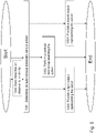
- Figure 5 is a flowchart depicting an exemplifying method according to embodiments of the inventive concept for indicating to a potential observer an ongoing or impending autonomous kinematic action of a vehicle 2.
- the exemplifying method which may be continuously repeated, comprises the following actions discussed with support from Figures 1-4 .
- the actions may be taken in any suitable order, for instance may Actions 1000 and 1001 alternatively be performed simultaneously or in a reverse order, and/or may Actions 1002, 1003 and 1004 be performed simultaneously.
- the intention indicating system 1 may determine - e.g. by means of the observer determining unit 100 - that an observer is in vicinity of the vehicle 2.
- the intention indicating system 1 only proceeds to Action 1001 and/or Action 1002 which will be further described below, when it is determined - e.g. with support from the optional detection system 9 - that someone is near the vehicle 2.
- the intention indicating system 1 determines - e.g. by means of the action determining unit 101 - an ongoing or impending autonomous kinematic action of the vehicle 2.
- the intention indicating system 1 determines - e.g. by means of the action determining unit 101 - an ongoing or impending autonomous kinematic action of the vehicle 2.
- the intention indicating system 1 performs - e.g. by means of the vertical motion performing unit 102 - a vertical vehicle motion representing the autonomous kinematic action, which vertical vehicle motion comprises raising and/or lowering a front portion 201 and/or a rear portion 202 of a vehicle body 20 of the vehicle 2.
- a physical vertical raising and/or lowering of at least a section and/or part of the vehicle body 20 is carried out indicative of the autonomous kinematic action.
- the indication of the autonomous kinematic action may be viewable from essentially all horizontal angles, such as from around 360 degrees of the vehicle 2, i.e. the vertical vehicle motion may be observable to an observer viewing the vehicle from essentially any direction, such as e.g. from the front, back and any of the sides thereof.
- vertical vehicle motions associated with autonomous kinematic actions may be more easily noticed by observers, which is a clear advantage over prior art technology for which many angles are hidden.
- the vertical vehicle motion comprises - when the autonomous kinematic action comprises a transition from a standstill state to a shut down state - lowering the vehicle body front portion 201 and rear portion 202 from a nominal suspension level L to a lower suspension level L.
- the vertical vehicle motion is adapted to - when the vehicle 2 is changing mode from an idle state where the vehicle may be on but standing still, to an off state and/or engine off state - lower the level of the vehicle body 20 in relation to the ground.
- the autonomous kinematic action of the vehicle 2 transitioning from the standstill state to the shut down state is communicated to an observer in an intuitive and easily viewable manner, by imitating a behaviour of "going to sleep" and/or "shutting off”.
- the vertical vehicle motion comprises - when the autonomous kinematic action comprises a transition from the shut down state to the standstill state - raising the vehicle body front portion 201 and rear portion 202 from the lower suspension level L to the nominal suspension level N.
- the vertical vehicle motion is adapted to - when the vehicle 2 is changing mode from an off state and/or engine off state to an idle state where the vehicle 2 may be on but standing still, such as e.g. prior to driving off - raise the level of the vehicle body 20 in relation to the ground.
- the autonomous kinematic action of the vehicle 2 transitioning from the shut down state to the standstill state is communicated to an observer in an intuitive and easily viewable manner, by imitating a behaviour of "waking up" and/or "being alert”.
- the vertical vehicle comprises - when the autonomous kinematic action comprises an acceleration - raising the front portion 201 and/or lowering the rear portion 202, e.g. from and/or in relation to the nominal suspension level N.
- the vertical vehicle motion is adapted to - when the vehicle is accelerating - tilt the vehicle body 20 such that the front portion 201 thereof becomes at a higher level e.g above the nominal suspension level N and/or the rear portion 202 thereof becomes at a lower level e.g. beneath the nominal suspension level N.
- the autonomous kinematic action of the vehicle 2 accelerating is communicated to an observer in an intuitive and easily viewable manner, by imitating a behaviour of "increasing speed" and/or “sprinting off".
- the vertical vehicle comprises - when the autonomous kinematic action comprises a deceleration - lowering the front portion 201 and/or raising the rear portion 202, e.g. from and/or in relation to the nominal suspension level N.
- the vertical vehicle motion is adapted to - when the vehicle 2 is decelerating - tilt the vehicle body such that the front portion 201 thereof becomes at a lower level e.g. beneath the nominal suspension level N and/or the rear portion 202 thereof becomes at a higher level e.g. above the nominal suspension level N.
- the autonomous kinematic action of the vehicle 2 decelerating is communicated to an observer in an intuitive and easily viewable manner, by imitating a behaviour of "slowing down", "braking” and/or "decreasing speed”.
- different autonomous kinematic actions may be represented by different types of vertical vehicle motions, with each respective vertical vehicle motion adapted to in an intuitive and/or human understandable manner signal the type of autonomous kinematic action it represents. Consequently, with the inventive concept, an ongoing or upcoming autonomous kinematic action may be communicated to an observer such as an external observer in an improved and intuitive manner, and subsequently, an observer may in an improved and intuitive manner perceive, derive and/or judge the ongoing or upcoming autonomous kinematic action and/or the type thereof.
- the performing of the vertical vehicle motion may be initiated a predeterminable period of time prior to the autonomous kinematic action starting.
- the vertical motion performing unit 102 may be adapted for initiating the performing of the vertical vehicle motion a predeterminable period of time prior to the autonomous kinematic action starting.
- the autonomous kinematic action may be initiated to be communicated ahead of time, i.e. prior to the vehicle 2 actually starting to perform said action. This gives an observer advance information of the action, and enables said observer to plan his or her behavior and/or react to the behaviors of the autonomous vehicle 2 ahead of time.
- the vehicle body 20 may be maintained at a suspension level effected by the vertical vehicle motion, for a predeterminable period of time and/or until the autonomous kinematic action is finalized.
- the vertical motion performing unit 102 may be adapted for maintaining the vehicle body 20 at a suspension level effected by the vertical vehicle motion, for a predeterminable period of time and/or until the autonomous kinematic action is finalized.
- the autonomous kinematic action may be communicated either during a selected period of time or until said action no longer is active and/or relevant. This gives an observer information about the action during a sufficient time period, and enables said observer to plan his or her behavior and/or react to behaviors of the autonomous vehicle 2 accordingly.
- the vertical vehicle motion may be provided by means of hydraulic, magnetic and/or air suspension of the vehicle body 20.
- the vehicle body 20 may be raised and/or lowered in a convenient manner, e.g. as commonly known in the art.
- the vertical vehicle motion may for instance be accomplished by means of one or more vehicle body suspension systems 7, which in any arbitrary manner may support raising and/or lowering of the front portion 201 and/or rear portion 202 of the vehicle body 20.
- the intention indicating system 1 may provide - e.g. by means of the optional light output providing unit 103 - with support from a light providing device 3 comprising one or more light sources 30 adapted to emit light, which light providing device 3 is provided continuously and/or intermittently along a majority of a horizontal circumference 4 of the vehicle 2, a visual light output visible at least from an outside of the vehicle 2 representing the autonomous kinematic action.
- a light providing device 3 comprising one or more light sources 30 adapted to emit light, which light providing device 3 is provided continuously and/or intermittently along a majority of a horizontal circumference 4 of the vehicle 2, a visual light output visible at least from an outside of the vehicle 2 representing the autonomous kinematic action.
- the autonomous kinematic action may to even greater extent be signalled in an intuitive and attention grabbing manner, and to even further extent be easily noticed by observers such as external observers. That is, a light emission indicative of the autonomous kinematic action is - additionally to performing of the vertical vehicle motion associated with said autonomous kinematic action - emitted with support from one or more light sources 30 distributed along the vehicle 2.
- a light emission indicative of the autonomous kinematic action is - additionally to performing of the vertical vehicle motion associated with said autonomous kinematic action - emitted with support from one or more light sources 30 distributed along the vehicle 2.
- said light providing device 3 may be viewable from essentially all horizontal angles, i.e. the light providing device 3 may be observable to an observer viewing the vehicle 2 from any direction.
- light outputs associated with autonomous kinematic actions may - in addition to vertical vehicle motions associated with said autonomous kinematic actions - be more easily noticed by observers.
- the light providing device 3 comprising one or more light sources 30 - such as a plurality thereof - and extending along at least a substantial portion of the vehicle's circumference 4, a greater variety of light output combinations representing different autonomous kinematic actions may be supported. That is, different autonomous kinematic actions may be represented by different types of light outputs, with each respective light output adapted to in an intuitive and/or human understandable manner signal the type of autonomous kinematic action it represents.
- the light output may, for instance, when the autonomous kinematic action comprises a transition from the standstill state to the shutdown, as shown in Figure 1a , comprise light emission from one or more light sources 30 of the light providing device 3 as considered appropriate to imitate a behaviour of "going to sleep".
- the light output may comprise light emitted in a pulsating manner, such as to imitate heartbeats and or breathing, for instance pulsating with a decreasing pace such as to imitate and/or resemble falling asleep.
- light may be emitted such as the light output appears to wander around the vehicle 2, for instance with decreasing pace.
- the light output may, for instance, when the autonomous kinematic action comprises a transition from the shutdown state to the standstill state, as shown in Figure 1b , comprise light emission from one or more light sources 30 of the light providing device 3 as considered appropriate to imitate a behaviour of "waking up.
- the light output may comprise light emitted in a pulsating manner, such as to imitate heartbeats and or breathing, for instance pulsating with an increasing pace.
- light may be emitted such as the light output appears to wander around the vehicle 2, for instance with increasing pace.
- the light output may, for instance, when the autonomous kinematic action comprises an acceleration, as shown in Figures 1c , comprise light emission from one or more light sources 30 of the light providing device 3 as considered appropriate to signal "increasing speed".
- the light output may then, as shown with support from Figure 2 and/or Figure 3 , optionally comprise light emission from the first light source 301 at a first time instant, light emission from the second light source 302 at a second time instant subsequent the first time instant, and light emission from the third light source 303 at a third time instant subsequent the second time instant.
- the autonomous kinematic action of vehicle acceleration is communicated to an observer in an even greater intuitive and easily viewable manner.
- the light output may, for instance, when the autonomous kinematic action comprises a deceleration, as shown in Figure 1d , comprise light emission from one or more light sources 30 of the light providing device 3 as considered appropriate to signal "decreasing speed and/or slowing down".
- the light output may then, as shown with support from Figure 2 and/or Figure 3 , optionally comprise light emission from the third light source 303 at a first time instant, light emission from the second light source 302 at a second time instant subsequent the first time instant, and light emission from the first light source 301 at a third time instant subsequent the second time instant.
- the at least first 301, second 302 and third light sources 303 emitting light in this specified order - which may be perceived as the light output moving in a forward direction of the vehicle 2 - the autonomous kinematic action of vehicle deceleration is communicated to an observer in an even greater intuitive and easily viewable manner.
- said action may be communicated to an observer in an - to even greater extent - improved and intuitive manner, and subsequently, an observer may - to even greater extent - in an improved and intuitive manner perceive, derive and/or judge the ongoing or upcoming autonomous kinematic action and/or the type thereof.
- the light providing device 3 may at least partly be visible from an inside of the vehicle 2.
- the light output may thereby be visible from an inside of the vehicle 2.
- the intention indicating system 1 may - e.g. by means of the optional sound output providing unit 104 - provide a sound output representing the autonomous kinematic action.
- the optional sound output providing unit 104 - provide a sound output representing the autonomous kinematic action.
- said autonomous kinematic action may to even greater extent be signalled in an intuitive and attention grabbing manner, and to further extent be easily noticed by observers.
- the sound output may for instance be provided with support from the speaker(s) system shown in Figure 4 .
Landscapes
- Engineering & Computer Science (AREA)
- Mechanical Engineering (AREA)
- Transportation (AREA)
- Automation & Control Theory (AREA)
- Physics & Mathematics (AREA)
- Chemical & Material Sciences (AREA)
- Combustion & Propulsion (AREA)
- General Physics & Mathematics (AREA)
- Lighting Device Outwards From Vehicle And Optical Signal (AREA)
- Acoustics & Sound (AREA)
- Human Computer Interaction (AREA)
- Aviation & Aerospace Engineering (AREA)
- Radar, Positioning & Navigation (AREA)
- Remote Sensing (AREA)
- Business, Economics & Management (AREA)
- Health & Medical Sciences (AREA)
- Artificial Intelligence (AREA)
- Evolutionary Computation (AREA)
- Game Theory and Decision Science (AREA)
- Medical Informatics (AREA)
Claims (15)
- Verfahren, das durch ein Absichtanzeigesystem (1) eines Fahrzeugs (2) durchgeführt wird, um einem möglichen Beobachter eine laufende oder eine bevorstehende eigenständige fahrbezogene Aktion des Fahrzeugs (2) anzuzeigen, wobei das Verfahren Folgendes umfasst:Bestimmen (1001) einer laufenden oder einer bevorstehenden eigenständigen fahrbezogenen Aktion des Fahrzeugs (2) undDurchführen (1002) einer vertikalen Fahrzeugbewegung, die die eigenständige fahrbezogene Aktion repräsentiert, wobei die vertikale Fahrzeugbewegung ein Anheben und/oder ein Absenken eines Frontabschnitts (201) und/oder eines Heckabschnitts (202) einer Fahrzeugkarosserie (20) des Fahrzeugs (2) umfasst und die vertikale Fahrzeugbewegung Folgendes umfasst:Absenken des Fahrzeugkarosseriefrontabschnitts (201) und des Fahrzeugkarosserieheckabschnitts (202) von einem nominellen Aufhängungsniveau (N) zu einem niedrigeren Aufhängungsniveau (L), wenn die eigenständige fahrbezogene Aktion einen Übergang von einem Stillstandszustand, der durch einen Leerlaufzustand, in dem das Fahrzeug eingeschaltet ist, jedoch stillsteht, repräsentiert wird, zu einem Abschaltzustand, der durch einen ausgeschalteten Fahrzeugzustand und/oder einen ausgeschalteten Kraftmaschinenzustand repräsentiert wird, umfasst; und/oderAnheben des Fahrzeugkarosseriefrontabschnitts (201) und des Fahrzeugkarosserieheckabschnitts (202) vom niedrigeren Aufhängungsniveau (L) zum nominellen Aufhängungsniveau (N), wenn die eigenständige fahrbezogene Aktion einen Übergang vom Abschaltzustand zum Stillstandszustand umfasst.
- Verfahren nach Anspruch 1, wobei das Durchführen der vertikalen Fahrzeugbewegung um einen vorgebbaren Zeitraum vor dem Starten der eigenständigen fahrbezogenen Aktion initiiert wird.
- Verfahren nach Anspruch 1 oder 2, wobei die Fahrzeugkarosserie für einen vorgebbaren Zeitraum und/oder bis zum Abschluss der eigenständigen fahrbezogenen Aktion bei einem Aufhängungsniveau, das durch die vertikale Fahrzeugbewegung bewirkt wird, gehalten wird.
- Verfahren nach einem der vorhergehenden Ansprüche, wobei das Durchführen (1002) einer vertikalen Fahrzeugbewegung ein Durchführen der vertikalen Fahrzeugbewegung mittels einer Hydraulik-, Magnet- und/oder Luftfederung der Fahrzeugkarosserie (20) umfasst.
- Verfahren nach einem der vorhergehenden Ansprüche, das ferner Folgendes umfasst:
Bestimmen (1000), dass sich ein Beobachter in der Umgebung des Fahrzeugs (2) befindet. - Verfahren nach einem der vorhergehenden Ansprüche, das ferner Folgendes umfasst:Bereitstellen (1003) einer Ausgabe sichtbaren Lichts, die mindestens von außerhalb des Fahrzeugs (2) sichtbar ist, wobei die Ausgabe sichtbaren Lichts die eigenständige fahrbezogene Aktion anzeigt, mit Unterstützung einer Lichtbereitstellungsvorrichtung (3), die eine oder mehrere Lichtquellen (30), die ausgelegt sind, Licht abzustrahlen, umfasst, wobei die Lichtbereitstellungsvorrichtung (3) entlang eines Hauptteils eines horizontalen Umfangs (4) des Fahrzeugs (2) kontinuierlich und/oder intermittierend bereitgestellt ist; und/oderBereitstellen (1004) einer Schallausgabe, die die eigenständige fahrbezogene Aktion repräsentiert.
- Verfahren nach Anspruch 6, wobei die Lichtbereitstellungsvorrichtung (3) mindestens teilweise durchsichtig und/oder lichtdurchlässig ist und das Bereitstellen (1004) einer Ausgabe sichtbaren Lichts dann das Bereitstellen der Ausgabe sichtbaren Lichts derart umfasst, dass sie zusätzlich mindestens teilweise von einem Innenraum des Fahrzeugs (2) sichtbar ist.
- Absichtanzeigesystem (1) eines Fahrzeugs (2), das ausgelegt ist, einem möglichen Beobachter eine laufende oder eine bevorstehende eigenständige fahrbezogene Aktion des Fahrzeugs (2) anzuzeigen, wobei das Absichtanzeigesystem (1) Folgendes umfasst:eine Aktionsbestimmungseinheit (101), die ausgelegt ist zum Bestimmen (1001) einer laufenden oder einer bevorstehenden eigenständigen fahrbezogenen Aktion des Fahrzeugs (2); undeine Vertikalbewegungsdurchführungseinheit (102), die ausgelegt ist zum Durchführen (1002) einer vertikalen Fahrzeugbewegung, die die eigenständige fahrbezogene Aktion repräsentiert, wobei die vertikale Fahrzeugbewegung ein Anheben und/oder ein Absenken eines Frontabschnitts (201) und/oder eines Heckabschnitts (202) einer Fahrzeugkarosserie (20) des Fahrzeugs (2) umfasst und die vertikale Fahrzeugbewegung Folgendes umfasst:Absenken des Fahrzeugkarosseriefrontabschnitts (201) und des Fahrzeugkarosserieheckabschnitts (202) von einem nominellen Aufhängungsniveau (N) zu einem niedrigeren Aufhängungsniveau (L), wenn die eigenständige fahrbezogene Aktion einen Übergang von einem Stillstandszustand, der durch einen Leerlaufzustand, in dem das Fahrzeug eingeschaltet, jedoch stillstehend ist, repräsentiert wird, zu einem Abschaltzustand, der durch einen ausgeschalteten Fahrzeugzustand und/oder einen ausgeschalteten Kraftmaschinenzustand repräsentiert wird, umfasst; und/oderAnheben des Fahrzeugkarosseriefrontabschnitts (201) und des Fahrzeugkarosserieheckabschnitts (202) vom niedrigeren Aufhängungsniveau (L) zum nominellem Aufhängungsniveau (N), wenn die eigenständige fahrbezogene Aktion einen Übergang vom Abschaltzustand zum Stillstandszustand umfasst.
- Absichtanzeigesystem (1) nach Anspruch 8, wobei die Vertikalbewegungsdurchführungseinheit (102) ausgelegt ist zum Initiieren des Durchführens der vertikalen Fahrzeugbewegung um einen vorgebbaren Zeitraum vor dem Starten der eigenständigen fahrbezogenen Aktion.
- Absichtanzeigesystem (1) nach Anspruch 8 oder 9, wobei die Vertikalbewegungsdurchführungseinheit (102) ausgelegt ist zum Halten der Fahrzeugkarosserie (20) für einen vorgebbaren Zeitraum und/oder bis zum Abschluss der eigenständigen fahrbezogenen Aktion bei einem Aufhängungsniveau, das durch die vertikale Fahrzeugbewegung bewirkt wird.
- Absichtanzeigesystem (1) nach einem der Ansprüche 8-10, wobei die vertikale Fahrzeugbewegung mittels einer Hydraulik-, Magnet- und/oder Luftfederung der Fahrzeugkarosserie (20) bereitgestellt wird.
- Absichtanzeigesystem (1) nach einem der Ansprüche 8-11, das ferner Folgendes umfasst:
eine Beobachterbestimmungseinheit (100), die ausgelegt ist zum Bestimmen (1000), dass ein Beobachter sich in der Umgebung des Fahrzeugs (2) befindet. - Absichtanzeigesystem (1) nach einem der Ansprüche 8-12, das ferner Folgendes umfasst:eine Lichtausgabebereitstellungseinheit (103), die ausgelegt ist zum Bereitstellen (1003) einer Ausgabe sichtbaren Lichts, die mindestens von außerhalb des Fahrzeugs (2) sichtbar ist und die eigenständige fahrbezogene Aktion repräsentiert, mit Unterstützung einer Lichtbereitstellungsvorrichtung (3), die eine oder mehrere Lichtquellen (30), die ausgelegt sind, Licht abzustrahlen, umfasst, wobei die Lichtbereitstellungsvorrichtung (3) entlang eines Hauptteils eines horizontalen Umfangs (4) des Fahrzeugs (4) kontinuierlich und/oder intermittierend bereitgestellt ist; und/odereine Schallausgabebereitstellungseinheit (104), die ausgelegt ist zum Bereitstellen (1004) einer Schallausgabe, die die eigenständige fahrbezogene Aktion repräsentiert.
- Absichtanzeigesystem (1) nach Anspruch 13, wobei die Lichtbereitstellungsvorrichtung (3) mindestens teilweise von einem Innenraum des Fahrzeugs (2) sichtbar ist.
- Fahrzeug (2), das ein Absichtanzeigesystem (1) nach einem der Ansprüche 8-14 umfasst.
Priority Applications (3)
| Application Number | Priority Date | Filing Date | Title |
|---|---|---|---|
| EP18181229.8A EP3590780B1 (de) | 2018-07-02 | 2018-07-02 | Verfahren und system zur anzeige einer autonomen kinematischen aktion eines fahrzeugs |
| CN201910553051.XA CN110667470B (zh) | 2018-07-02 | 2019-06-25 | 用于指示车辆的自主运动学动作的方法和系统 |
| US16/455,817 US11285771B2 (en) | 2018-07-02 | 2019-06-28 | Method and system for indicating an autonomous kinematic action of a vehicle |
Applications Claiming Priority (1)
| Application Number | Priority Date | Filing Date | Title |
|---|---|---|---|
| EP18181229.8A EP3590780B1 (de) | 2018-07-02 | 2018-07-02 | Verfahren und system zur anzeige einer autonomen kinematischen aktion eines fahrzeugs |
Publications (2)
| Publication Number | Publication Date |
|---|---|
| EP3590780A1 EP3590780A1 (de) | 2020-01-08 |
| EP3590780B1 true EP3590780B1 (de) | 2022-09-07 |
Family
ID=62842003
Family Applications (1)
| Application Number | Title | Priority Date | Filing Date |
|---|---|---|---|
| EP18181229.8A Active EP3590780B1 (de) | 2018-07-02 | 2018-07-02 | Verfahren und system zur anzeige einer autonomen kinematischen aktion eines fahrzeugs |
Country Status (3)
| Country | Link |
|---|---|
| US (1) | US11285771B2 (de) |
| EP (1) | EP3590780B1 (de) |
| CN (1) | CN110667470B (de) |
Families Citing this family (2)
| Publication number | Priority date | Publication date | Assignee | Title |
|---|---|---|---|---|
| US20200130454A1 (en) * | 2018-10-30 | 2020-04-30 | Air Lift Company | Method of operating vehicle control system |
| JP7790974B2 (ja) * | 2019-07-02 | 2025-12-23 | モルガン アドゥヒーシブス カンパニー, エルエルシー | シリコーン組成物の硬化を促進する方法 |
Family Cites Families (21)
| Publication number | Priority date | Publication date | Assignee | Title |
|---|---|---|---|---|
| US6993422B2 (en) * | 2003-09-25 | 2006-01-31 | Autoliv Asp, Inc. | Pre-crash nose dipping system |
| JP2005271718A (ja) * | 2004-03-24 | 2005-10-06 | Aisin Seiki Co Ltd | 車高調節装置 |
| CN1883982B (zh) * | 2005-06-24 | 2010-09-01 | 龚立新 | 一种车辆状态信号系统 |
| EP2531988A4 (de) * | 2010-02-04 | 2015-09-09 | Snap On Tools Corp | Drehbare und animierte benutzeranzeigeoberfläche |
| JP5996947B2 (ja) * | 2012-06-29 | 2016-09-21 | 株式会社ショーワ | 車両の車高調整装置 |
| JP6266870B2 (ja) * | 2012-09-19 | 2018-01-24 | 株式会社ショーワ | 自動二輪車 |
| JP6012449B2 (ja) * | 2012-12-14 | 2016-10-25 | 株式会社ショーワ | 自動二輪車の車高調整装置 |
| JP6178149B2 (ja) * | 2013-07-24 | 2017-08-09 | ヤンマー株式会社 | トラクター |
| DE102013017209B4 (de) * | 2013-10-16 | 2017-07-27 | Audi Ag | Verfahren zum Betrieb eines Fahrerassistenzsystems eines Kraftfahrzeugs und Kraftfahrzeug |
| DE102013018784B4 (de) * | 2013-11-08 | 2016-02-18 | Audi Ag | Fahrzeug mit Beleuchtungsvorrichtung mit einer längsförmigen Beleuchtungseinrichtung |
| DE102013020933A1 (de) * | 2013-12-11 | 2015-06-11 | Daimler Ag | Verfahren zum automatischen Betrieb eines Fahrzeuges |
| US10377371B2 (en) * | 2014-04-02 | 2019-08-13 | ClearMotion, Inc. | Active safety suspension system |
| US9475422B2 (en) | 2014-05-22 | 2016-10-25 | Applied Invention, Llc | Communication between autonomous vehicle and external observers |
| KR101622095B1 (ko) * | 2014-06-02 | 2016-05-18 | 현대모비스 주식회사 | 자동차의 조명 장치 |
| US9868332B2 (en) * | 2015-06-03 | 2018-01-16 | ClearMotion, Inc. | Methods and systems for controlling vehicle body motion and occupant experience |
| WO2016210099A1 (en) * | 2015-06-23 | 2016-12-29 | Polar Tank Trailer, Llc | Automatically deploying lift axle control system |
| US9694736B2 (en) * | 2015-09-30 | 2017-07-04 | Nissan North America, Inc. | Vehicle state indication system |
| US9902311B2 (en) * | 2016-02-22 | 2018-02-27 | Uber Technologies, Inc. | Lighting device for a vehicle |
| US20180339568A1 (en) * | 2017-05-23 | 2018-11-29 | Dallas Smith Corp. | System for safely kneeling a vehicle |
| EP3590762B1 (de) * | 2018-07-02 | 2024-09-11 | Volvo Car Corporation | Verfahren und system zur anzeige einer autonomen fahraktion eines fahrzeugs |
| EP3590741B1 (de) * | 2018-07-02 | 2022-06-08 | Volvo Car Corporation | Verfahren und system zur anzeige einer autonomen kinematischen aktion eines fahrzeugs |
-
2018
- 2018-07-02 EP EP18181229.8A patent/EP3590780B1/de active Active
-
2019
- 2019-06-25 CN CN201910553051.XA patent/CN110667470B/zh active Active
- 2019-06-28 US US16/455,817 patent/US11285771B2/en active Active
Also Published As
| Publication number | Publication date |
|---|---|
| CN110667470B (zh) | 2023-03-31 |
| US11285771B2 (en) | 2022-03-29 |
| US20200004254A1 (en) | 2020-01-02 |
| EP3590780A1 (de) | 2020-01-08 |
| CN110667470A (zh) | 2020-01-10 |
Similar Documents
| Publication | Publication Date | Title |
|---|---|---|
| JP7597185B2 (ja) | 報知装置 | |
| JP6650250B2 (ja) | 伝達を用いる予測的運転者支援を行う方法およびシステム、並びにそのようなシステムを備えた車両 | |
| US10304340B2 (en) | Control device mounted on vehicle and method for controlling the same | |
| US20180222424A1 (en) | Collision Prevention System | |
| CN107107818B (zh) | 方向指示灯装置以及防撞系统 | |
| US10913389B2 (en) | Method and system for indicating an autonomous kinematic action of a vehicle | |
| US20200384240A1 (en) | Lighting device, method and program for countering motion sickness experienced in a vehicle | |
| JP2016162448A (ja) | 車両の物体検出及び通知システム | |
| CN108349430A (zh) | 车辆用照明装置、车辆系统以及车辆 | |
| US11257372B2 (en) | Reverse-facing anti-collision system | |
| US11285771B2 (en) | Method and system for indicating an autonomous kinematic action of a vehicle | |
| CN108819940B (zh) | 一种车道偏离辅助制动系统的控制方法、系统及汽车 | |
| US11338734B2 (en) | Method and system for indicating an autonomous kinematic action of a vehicle | |
| US20060244633A1 (en) | Vehicle communication device and method of controlling the same | |
| CN108694845A (zh) | 一种车辆驾驶的提醒方法和装置 | |
| CN115366782A (zh) | 汽车及信息展示方法 | |
| CN113442826A (zh) | 一种智能主动警示型刹车灯控制方法及系统 | |
| CN203580760U (zh) | 一种车辆制动提示装置 | |
| CN111762157A (zh) | 相遇警示方法及相遇警示系统 | |
| JP2020144777A (ja) | 車両システム | |
| EP4667314A1 (de) | Verfahren zur anpassung des fahrens eines ersten fahrzeugs auf basis einer unzureichenden fahrzeugbeleuchtung eines zweiten fahrzeugs | |
| JP2008028819A (ja) | 車両用通信装置 | |
| CN118494341A (zh) | 一种车辆的预警提醒方法及系统 | |
| JP2004017905A (ja) | 車両のストップランプ装置 | |
| CN118182526A (zh) | 一种车辆控制方法、系统、存储介质及车辆 |
Legal Events
| Date | Code | Title | Description |
|---|---|---|---|
| PUAI | Public reference made under article 153(3) epc to a published international application that has entered the european phase |
Free format text: ORIGINAL CODE: 0009012 |
|
| STAA | Information on the status of an ep patent application or granted ep patent |
Free format text: STATUS: THE APPLICATION HAS BEEN PUBLISHED |
|
| AK | Designated contracting states |
Kind code of ref document: A1 Designated state(s): AL AT BE BG CH CY CZ DE DK EE ES FI FR GB GR HR HU IE IS IT LI LT LU LV MC MK MT NL NO PL PT RO RS SE SI SK SM TR |
|
| AX | Request for extension of the european patent |
Extension state: BA ME |
|
| STAA | Information on the status of an ep patent application or granted ep patent |
Free format text: STATUS: REQUEST FOR EXAMINATION WAS MADE |
|
| 17P | Request for examination filed |
Effective date: 20200708 |
|
| RBV | Designated contracting states (corrected) |
Designated state(s): AL AT BE BG CH CY CZ DE DK EE ES FI FR GB GR HR HU IE IS IT LI LT LU LV MC MK MT NL NO PL PT RO RS SE SI SK SM TR |
|
| STAA | Information on the status of an ep patent application or granted ep patent |
Free format text: STATUS: EXAMINATION IS IN PROGRESS |
|
| 17Q | First examination report despatched |
Effective date: 20210201 |
|
| GRAP | Despatch of communication of intention to grant a patent |
Free format text: ORIGINAL CODE: EPIDOSNIGR1 |
|
| STAA | Information on the status of an ep patent application or granted ep patent |
Free format text: STATUS: GRANT OF PATENT IS INTENDED |
|
| INTG | Intention to grant announced |
Effective date: 20220316 |
|
| GRAS | Grant fee paid |
Free format text: ORIGINAL CODE: EPIDOSNIGR3 |
|
| GRAA | (expected) grant |
Free format text: ORIGINAL CODE: 0009210 |
|
| STAA | Information on the status of an ep patent application or granted ep patent |
Free format text: STATUS: THE PATENT HAS BEEN GRANTED |
|
| AK | Designated contracting states |
Kind code of ref document: B1 Designated state(s): AL AT BE BG CH CY CZ DE DK EE ES FI FR GB GR HR HU IE IS IT LI LT LU LV MC MK MT NL NO PL PT RO RS SE SI SK SM TR |
|
| REG | Reference to a national code |
Ref country code: GB Ref legal event code: FG4D |
|
| REG | Reference to a national code |
Ref country code: CH Ref legal event code: EP Ref country code: AT Ref legal event code: REF Ref document number: 1516804 Country of ref document: AT Kind code of ref document: T Effective date: 20220915 |
|
| REG | Reference to a national code |
Ref country code: IE Ref legal event code: FG4D |
|
| REG | Reference to a national code |
Ref country code: DE Ref legal event code: R096 Ref document number: 602018040237 Country of ref document: DE |
|
| REG | Reference to a national code |
Ref country code: LT Ref legal event code: MG9D |
|
| REG | Reference to a national code |
Ref country code: NL Ref legal event code: MP Effective date: 20220907 |
|
| PG25 | Lapsed in a contracting state [announced via postgrant information from national office to epo] |
Ref country code: SE Free format text: LAPSE BECAUSE OF FAILURE TO SUBMIT A TRANSLATION OF THE DESCRIPTION OR TO PAY THE FEE WITHIN THE PRESCRIBED TIME-LIMIT Effective date: 20220907 Ref country code: RS Free format text: LAPSE BECAUSE OF FAILURE TO SUBMIT A TRANSLATION OF THE DESCRIPTION OR TO PAY THE FEE WITHIN THE PRESCRIBED TIME-LIMIT Effective date: 20220907 Ref country code: NO Free format text: LAPSE BECAUSE OF FAILURE TO SUBMIT A TRANSLATION OF THE DESCRIPTION OR TO PAY THE FEE WITHIN THE PRESCRIBED TIME-LIMIT Effective date: 20221207 Ref country code: LV Free format text: LAPSE BECAUSE OF FAILURE TO SUBMIT A TRANSLATION OF THE DESCRIPTION OR TO PAY THE FEE WITHIN THE PRESCRIBED TIME-LIMIT Effective date: 20220907 Ref country code: LT Free format text: LAPSE BECAUSE OF FAILURE TO SUBMIT A TRANSLATION OF THE DESCRIPTION OR TO PAY THE FEE WITHIN THE PRESCRIBED TIME-LIMIT Effective date: 20220907 Ref country code: FI Free format text: LAPSE BECAUSE OF FAILURE TO SUBMIT A TRANSLATION OF THE DESCRIPTION OR TO PAY THE FEE WITHIN THE PRESCRIBED TIME-LIMIT Effective date: 20220907 |
|
| REG | Reference to a national code |
Ref country code: AT Ref legal event code: MK05 Ref document number: 1516804 Country of ref document: AT Kind code of ref document: T Effective date: 20220907 |
|
| PG25 | Lapsed in a contracting state [announced via postgrant information from national office to epo] |
Ref country code: HR Free format text: LAPSE BECAUSE OF FAILURE TO SUBMIT A TRANSLATION OF THE DESCRIPTION OR TO PAY THE FEE WITHIN THE PRESCRIBED TIME-LIMIT Effective date: 20220907 Ref country code: GR Free format text: LAPSE BECAUSE OF FAILURE TO SUBMIT A TRANSLATION OF THE DESCRIPTION OR TO PAY THE FEE WITHIN THE PRESCRIBED TIME-LIMIT Effective date: 20221208 |
|
| PG25 | Lapsed in a contracting state [announced via postgrant information from national office to epo] |
Ref country code: SM Free format text: LAPSE BECAUSE OF FAILURE TO SUBMIT A TRANSLATION OF THE DESCRIPTION OR TO PAY THE FEE WITHIN THE PRESCRIBED TIME-LIMIT Effective date: 20220907 Ref country code: RO Free format text: LAPSE BECAUSE OF FAILURE TO SUBMIT A TRANSLATION OF THE DESCRIPTION OR TO PAY THE FEE WITHIN THE PRESCRIBED TIME-LIMIT Effective date: 20220907 Ref country code: PT Free format text: LAPSE BECAUSE OF FAILURE TO SUBMIT A TRANSLATION OF THE DESCRIPTION OR TO PAY THE FEE WITHIN THE PRESCRIBED TIME-LIMIT Effective date: 20230109 Ref country code: ES Free format text: LAPSE BECAUSE OF FAILURE TO SUBMIT A TRANSLATION OF THE DESCRIPTION OR TO PAY THE FEE WITHIN THE PRESCRIBED TIME-LIMIT Effective date: 20220907 Ref country code: CZ Free format text: LAPSE BECAUSE OF FAILURE TO SUBMIT A TRANSLATION OF THE DESCRIPTION OR TO PAY THE FEE WITHIN THE PRESCRIBED TIME-LIMIT Effective date: 20220907 Ref country code: AT Free format text: LAPSE BECAUSE OF FAILURE TO SUBMIT A TRANSLATION OF THE DESCRIPTION OR TO PAY THE FEE WITHIN THE PRESCRIBED TIME-LIMIT Effective date: 20220907 |
|
| PG25 | Lapsed in a contracting state [announced via postgrant information from national office to epo] |
Ref country code: SK Free format text: LAPSE BECAUSE OF FAILURE TO SUBMIT A TRANSLATION OF THE DESCRIPTION OR TO PAY THE FEE WITHIN THE PRESCRIBED TIME-LIMIT Effective date: 20220907 Ref country code: PL Free format text: LAPSE BECAUSE OF FAILURE TO SUBMIT A TRANSLATION OF THE DESCRIPTION OR TO PAY THE FEE WITHIN THE PRESCRIBED TIME-LIMIT Effective date: 20220907 Ref country code: IS Free format text: LAPSE BECAUSE OF FAILURE TO SUBMIT A TRANSLATION OF THE DESCRIPTION OR TO PAY THE FEE WITHIN THE PRESCRIBED TIME-LIMIT Effective date: 20230107 Ref country code: EE Free format text: LAPSE BECAUSE OF FAILURE TO SUBMIT A TRANSLATION OF THE DESCRIPTION OR TO PAY THE FEE WITHIN THE PRESCRIBED TIME-LIMIT Effective date: 20220907 |
|
| REG | Reference to a national code |
Ref country code: DE Ref legal event code: R097 Ref document number: 602018040237 Country of ref document: DE |
|
| PG25 | Lapsed in a contracting state [announced via postgrant information from national office to epo] |
Ref country code: NL Free format text: LAPSE BECAUSE OF FAILURE TO SUBMIT A TRANSLATION OF THE DESCRIPTION OR TO PAY THE FEE WITHIN THE PRESCRIBED TIME-LIMIT Effective date: 20220907 Ref country code: AL Free format text: LAPSE BECAUSE OF FAILURE TO SUBMIT A TRANSLATION OF THE DESCRIPTION OR TO PAY THE FEE WITHIN THE PRESCRIBED TIME-LIMIT Effective date: 20220907 |
|
| PLBE | No opposition filed within time limit |
Free format text: ORIGINAL CODE: 0009261 |
|
| STAA | Information on the status of an ep patent application or granted ep patent |
Free format text: STATUS: NO OPPOSITION FILED WITHIN TIME LIMIT |
|
| PG25 | Lapsed in a contracting state [announced via postgrant information from national office to epo] |
Ref country code: DK Free format text: LAPSE BECAUSE OF FAILURE TO SUBMIT A TRANSLATION OF THE DESCRIPTION OR TO PAY THE FEE WITHIN THE PRESCRIBED TIME-LIMIT Effective date: 20220907 |
|
| 26N | No opposition filed |
Effective date: 20230608 |
|
| PG25 | Lapsed in a contracting state [announced via postgrant information from national office to epo] |
Ref country code: SI Free format text: LAPSE BECAUSE OF FAILURE TO SUBMIT A TRANSLATION OF THE DESCRIPTION OR TO PAY THE FEE WITHIN THE PRESCRIBED TIME-LIMIT Effective date: 20220907 |
|
| P01 | Opt-out of the competence of the unified patent court (upc) registered |
Effective date: 20231212 |
|
| PG25 | Lapsed in a contracting state [announced via postgrant information from national office to epo] |
Ref country code: MC Free format text: LAPSE BECAUSE OF FAILURE TO SUBMIT A TRANSLATION OF THE DESCRIPTION OR TO PAY THE FEE WITHIN THE PRESCRIBED TIME-LIMIT Effective date: 20220907 |
|
| PG25 | Lapsed in a contracting state [announced via postgrant information from national office to epo] |
Ref country code: MC Free format text: LAPSE BECAUSE OF FAILURE TO SUBMIT A TRANSLATION OF THE DESCRIPTION OR TO PAY THE FEE WITHIN THE PRESCRIBED TIME-LIMIT Effective date: 20220907 |
|
| REG | Reference to a national code |
Ref country code: CH Ref legal event code: PL |
|
| REG | Reference to a national code |
Ref country code: BE Ref legal event code: MM Effective date: 20230731 |
|
| PG25 | Lapsed in a contracting state [announced via postgrant information from national office to epo] |
Ref country code: LU Free format text: LAPSE BECAUSE OF NON-PAYMENT OF DUE FEES Effective date: 20230702 |
|
| PG25 | Lapsed in a contracting state [announced via postgrant information from national office to epo] |
Ref country code: LU Free format text: LAPSE BECAUSE OF NON-PAYMENT OF DUE FEES Effective date: 20230702 |
|
| REG | Reference to a national code |
Ref country code: IE Ref legal event code: MM4A |
|
| PG25 | Lapsed in a contracting state [announced via postgrant information from national office to epo] |
Ref country code: CH Free format text: LAPSE BECAUSE OF NON-PAYMENT OF DUE FEES Effective date: 20230731 |
|
| PG25 | Lapsed in a contracting state [announced via postgrant information from national office to epo] |
Ref country code: BE Free format text: LAPSE BECAUSE OF NON-PAYMENT OF DUE FEES Effective date: 20230731 |
|
| PG25 | Lapsed in a contracting state [announced via postgrant information from national office to epo] |
Ref country code: IE Free format text: LAPSE BECAUSE OF NON-PAYMENT OF DUE FEES Effective date: 20230702 |
|
| PG25 | Lapsed in a contracting state [announced via postgrant information from national office to epo] |
Ref country code: IE Free format text: LAPSE BECAUSE OF NON-PAYMENT OF DUE FEES Effective date: 20230702 |
|
| PGFP | Annual fee paid to national office [announced via postgrant information from national office to epo] |
Ref country code: IT Payment date: 20240619 Year of fee payment: 7 |
|
| PG25 | Lapsed in a contracting state [announced via postgrant information from national office to epo] |
Ref country code: BG Free format text: LAPSE BECAUSE OF FAILURE TO SUBMIT A TRANSLATION OF THE DESCRIPTION OR TO PAY THE FEE WITHIN THE PRESCRIBED TIME-LIMIT Effective date: 20220907 |
|
| PG25 | Lapsed in a contracting state [announced via postgrant information from national office to epo] |
Ref country code: BG Free format text: LAPSE BECAUSE OF FAILURE TO SUBMIT A TRANSLATION OF THE DESCRIPTION OR TO PAY THE FEE WITHIN THE PRESCRIBED TIME-LIMIT Effective date: 20220907 |
|
| PGFP | Annual fee paid to national office [announced via postgrant information from national office to epo] |
Ref country code: GB Payment date: 20250619 Year of fee payment: 8 |
|
| PGFP | Annual fee paid to national office [announced via postgrant information from national office to epo] |
Ref country code: FR Payment date: 20250620 Year of fee payment: 8 |
|
| PG25 | Lapsed in a contracting state [announced via postgrant information from national office to epo] |
Ref country code: CY Free format text: LAPSE BECAUSE OF FAILURE TO SUBMIT A TRANSLATION OF THE DESCRIPTION OR TO PAY THE FEE WITHIN THE PRESCRIBED TIME-LIMIT; INVALID AB INITIO Effective date: 20180702 |
|
| PG25 | Lapsed in a contracting state [announced via postgrant information from national office to epo] |
Ref country code: HU Free format text: LAPSE BECAUSE OF FAILURE TO SUBMIT A TRANSLATION OF THE DESCRIPTION OR TO PAY THE FEE WITHIN THE PRESCRIBED TIME-LIMIT; INVALID AB INITIO Effective date: 20180702 |
|
| PGFP | Annual fee paid to national office [announced via postgrant information from national office to epo] |
Ref country code: DE Payment date: 20250620 Year of fee payment: 8 |
|
| PG25 | Lapsed in a contracting state [announced via postgrant information from national office to epo] |
Ref country code: TR Free format text: LAPSE BECAUSE OF FAILURE TO SUBMIT A TRANSLATION OF THE DESCRIPTION OR TO PAY THE FEE WITHIN THE PRESCRIBED TIME-LIMIT Effective date: 20220907 |