EP3590876B1 - Papierpfadstruktur, stapler, drucker und verfahren zum betrieb einer papierpfadstruktur - Google Patents
Papierpfadstruktur, stapler, drucker und verfahren zum betrieb einer papierpfadstruktur Download PDFInfo
- Publication number
- EP3590876B1 EP3590876B1 EP18181318.9A EP18181318A EP3590876B1 EP 3590876 B1 EP3590876 B1 EP 3590876B1 EP 18181318 A EP18181318 A EP 18181318A EP 3590876 B1 EP3590876 B1 EP 3590876B1
- Authority
- EP
- European Patent Office
- Prior art keywords
- paper
- path section
- sheet
- path
- sheets
- Prior art date
- Legal status (The legal status is an assumption and is not a legal conclusion. Google has not performed a legal analysis and makes no representation as to the accuracy of the status listed.)
- Active
Links
Images



Classifications
-
- B—PERFORMING OPERATIONS; TRANSPORTING
- B65—CONVEYING; PACKING; STORING; HANDLING THIN OR FILAMENTARY MATERIAL
- B65H—HANDLING THIN OR FILAMENTARY MATERIAL, e.g. SHEETS, WEBS, CABLES
- B65H5/00—Feeding articles separated from piles; Feeding articles to machines
- B65H5/26—Duplicate, alternate, selective, or coacting feeds
-
- B—PERFORMING OPERATIONS; TRANSPORTING
- B65—CONVEYING; PACKING; STORING; HANDLING THIN OR FILAMENTARY MATERIAL
- B65H—HANDLING THIN OR FILAMENTARY MATERIAL, e.g. SHEETS, WEBS, CABLES
- B65H15/00—Overturning articles
- B65H15/004—Overturning articles employing rollers
-
- B—PERFORMING OPERATIONS; TRANSPORTING
- B65—CONVEYING; PACKING; STORING; HANDLING THIN OR FILAMENTARY MATERIAL
- B65H—HANDLING THIN OR FILAMENTARY MATERIAL, e.g. SHEETS, WEBS, CABLES
- B65H29/00—Delivering or advancing articles from machines; Advancing articles to or into piles
- B65H29/12—Delivering or advancing articles from machines; Advancing articles to or into piles by means of the nip between two, or between two sets of, moving tapes or bands or rollers
- B65H29/125—Delivering or advancing articles from machines; Advancing articles to or into piles by means of the nip between two, or between two sets of, moving tapes or bands or rollers between two sets of rollers
-
- B—PERFORMING OPERATIONS; TRANSPORTING
- B65—CONVEYING; PACKING; STORING; HANDLING THIN OR FILAMENTARY MATERIAL
- B65H—HANDLING THIN OR FILAMENTARY MATERIAL, e.g. SHEETS, WEBS, CABLES
- B65H29/00—Delivering or advancing articles from machines; Advancing articles to or into piles
- B65H29/20—Delivering or advancing articles from machines; Advancing articles to or into piles by contact with rotating friction members, e.g. rollers, brushes, or cylinders
- B65H29/22—Delivering or advancing articles from machines; Advancing articles to or into piles by contact with rotating friction members, e.g. rollers, brushes, or cylinders and introducing into a pile
-
- B—PERFORMING OPERATIONS; TRANSPORTING
- B65—CONVEYING; PACKING; STORING; HANDLING THIN OR FILAMENTARY MATERIAL
- B65H—HANDLING THIN OR FILAMENTARY MATERIAL, e.g. SHEETS, WEBS, CABLES
- B65H29/00—Delivering or advancing articles from machines; Advancing articles to or into piles
- B65H29/58—Article switches or diverters
- B65H29/60—Article switches or diverters diverting the stream into alternative paths
-
- B—PERFORMING OPERATIONS; TRANSPORTING
- B65—CONVEYING; PACKING; STORING; HANDLING THIN OR FILAMENTARY MATERIAL
- B65H—HANDLING THIN OR FILAMENTARY MATERIAL, e.g. SHEETS, WEBS, CABLES
- B65H31/00—Pile receivers
- B65H31/04—Pile receivers with movable end support arranged to recede as pile accumulates
- B65H31/08—Pile receivers with movable end support arranged to recede as pile accumulates the articles being piled one above another
- B65H31/10—Pile receivers with movable end support arranged to recede as pile accumulates the articles being piled one above another and applied at the top of the pile
-
- B—PERFORMING OPERATIONS; TRANSPORTING
- B65—CONVEYING; PACKING; STORING; HANDLING THIN OR FILAMENTARY MATERIAL
- B65H—HANDLING THIN OR FILAMENTARY MATERIAL, e.g. SHEETS, WEBS, CABLES
- B65H2301/00—Handling processes for sheets or webs
- B65H2301/10—Selective handling processes
- B65H2301/13—Relative to size or orientation of the material
- B65H2301/133—Face-up or face-down handling mode
-
- B—PERFORMING OPERATIONS; TRANSPORTING
- B65—CONVEYING; PACKING; STORING; HANDLING THIN OR FILAMENTARY MATERIAL
- B65H—HANDLING THIN OR FILAMENTARY MATERIAL, e.g. SHEETS, WEBS, CABLES
- B65H2301/00—Handling processes for sheets or webs
- B65H2301/30—Orientation, displacement, position of the handled material
- B65H2301/33—Modifying, selecting, changing orientation
-
- B—PERFORMING OPERATIONS; TRANSPORTING
- B65—CONVEYING; PACKING; STORING; HANDLING THIN OR FILAMENTARY MATERIAL
- B65H—HANDLING THIN OR FILAMENTARY MATERIAL, e.g. SHEETS, WEBS, CABLES
- B65H2301/00—Handling processes for sheets or webs
- B65H2301/30—Orientation, displacement, position of the handled material
- B65H2301/33—Modifying, selecting, changing orientation
- B65H2301/332—Turning, overturning
- B65H2301/3321—Turning, overturning kinetic therefor
- B65H2301/33214—Turning, overturning kinetic therefor about an axis perpendicular to the direction of displacement and parallel to the surface of material
-
- B—PERFORMING OPERATIONS; TRANSPORTING
- B65—CONVEYING; PACKING; STORING; HANDLING THIN OR FILAMENTARY MATERIAL
- B65H—HANDLING THIN OR FILAMENTARY MATERIAL, e.g. SHEETS, WEBS, CABLES
- B65H2301/00—Handling processes for sheets or webs
- B65H2301/30—Orientation, displacement, position of the handled material
- B65H2301/33—Modifying, selecting, changing orientation
- B65H2301/333—Inverting
- B65H2301/3331—Involving forward reverse transporting means
- B65H2301/33312—Involving forward reverse transporting means forward reverse rollers pairs
-
- B—PERFORMING OPERATIONS; TRANSPORTING
- B65—CONVEYING; PACKING; STORING; HANDLING THIN OR FILAMENTARY MATERIAL
- B65H—HANDLING THIN OR FILAMENTARY MATERIAL, e.g. SHEETS, WEBS, CABLES
- B65H2301/00—Handling processes for sheets or webs
- B65H2301/30—Orientation, displacement, position of the handled material
- B65H2301/34—Modifying, selecting, changing direction of displacement
- B65H2301/342—Modifying, selecting, changing direction of displacement with change of plane of displacement
- B65H2301/3423—Modifying, selecting, changing direction of displacement with change of plane of displacement by travelling an angled curved path section for overturning and changing feeding direction
-
- B—PERFORMING OPERATIONS; TRANSPORTING
- B65—CONVEYING; PACKING; STORING; HANDLING THIN OR FILAMENTARY MATERIAL
- B65H—HANDLING THIN OR FILAMENTARY MATERIAL, e.g. SHEETS, WEBS, CABLES
- B65H2301/00—Handling processes for sheets or webs
- B65H2301/40—Type of handling process
- B65H2301/42—Piling, depiling, handling piles
- B65H2301/421—Forming a pile
- B65H2301/4212—Forming a pile of articles substantially horizontal
-
- B—PERFORMING OPERATIONS; TRANSPORTING
- B65—CONVEYING; PACKING; STORING; HANDLING THIN OR FILAMENTARY MATERIAL
- B65H—HANDLING THIN OR FILAMENTARY MATERIAL, e.g. SHEETS, WEBS, CABLES
- B65H2301/00—Handling processes for sheets or webs
- B65H2301/40—Type of handling process
- B65H2301/44—Moving, forwarding, guiding material
- B65H2301/448—Diverting
- B65H2301/4482—Diverting to multiple paths, i.e. more than 2
- B65H2301/44822—3 paths
-
- B—PERFORMING OPERATIONS; TRANSPORTING
- B65—CONVEYING; PACKING; STORING; HANDLING THIN OR FILAMENTARY MATERIAL
- B65H—HANDLING THIN OR FILAMENTARY MATERIAL, e.g. SHEETS, WEBS, CABLES
- B65H2801/00—Application field
- B65H2801/03—Image reproduction devices
- B65H2801/06—Office-type machines, e.g. photocopiers
Definitions
- the present invention relates to a paper path structure, in particular to a paper path structure for a printer or for a stacker that can be combined with a printer.
- the invention also relates to a stacker comprising a paper path structure and to a printer comprising a paper path structure. Furthermore, the invention relates to a method for operating a paper path structure.
- Imaging devices in particular printers, produce their output at a faster and faster rate with each new generation.
- the output in particular sheets of paper marked with ink, or, in other words, printed paper, usually needs to be sorted and/or stacked at a high rate.
- office and factory space is usually at a premium and it is therefore strived for compact devices.
- invert or: "flip" printed sheets, i.e., to receive a paper with its front side in a first orientation (for example, front-side up) and to output the same printed sheet having the reversed orientation (e. g. front-side down).
- EP 1 213 624 A2 a sheet inverter system for a copier or a printer is described.
- FR 2 760 733 A1 discloses a stacking machine for paper sheets with a paper path structure according to the preamble of claim 1.
- the invention provides a paper path structure comprising:
- the paper path structure is configured to:
- the flipping device is a structure that is configured flip a sheet of paper, such that the orientation of the sheet is reversed. Thereby the front and back facing sides of the sheet are interchanged.
- the flipping device comprises a flipping wheel provided with recesses configured to receive and hold a leading edge of a sheet, such that the sheet is flipped by a rotation of the flipping wheel.
- Flipping a sheet of paper in this context means in particular that an orientation of the sheet of paper is changed in such a way that a side that has been face-down before the flipping is face-up after the flipping and that a side of the sheet of paper that has been face-up before the flipping is face-down after the flipping.
- no further rotations along other axes of the sheet of paper are performed during the flipping.
- flipping a sheet of paper does not necessarily mean that a sheet of paper is parallel to the ground before the flipping and parallel to the ground (with the reversed orientation) after the flipping but also may comprise procedures where a sheet of paper that has an angle of less than 90 degrees with respect to the ground is changed into another orientation with an angle of less than 90 degrees to the ground, wherein a side of the sheet of paper that has been pointing at the ground before the flipping is after the flipping pointing away from the ground and vice versa.
- the flipping device is, in particular, configured to receive a sheet of paper with a first side of the sheet oriented towards the center of the wheel, to turn while carrying the sheet of paper (for example by exerting a force on the sheet of paper) and to deposit the received sheet of paper with its first side up in a receptacle or another path section of the paper path structure.
- the flipping device may be able to flip the sheet while turning less than 180 degrees, in particular by turning less than 150 degrees.
- a path section may in particular comprise guiding elements configured to guide the sheets of paper along a certain geometrical path through the path section, for example passive rollers that are not driven and/or active rollers that are driven and are configured to actively move the sheets of paper coming into contact with the active rollers as well as other elements known in the prior art, e.g. for bending sheets and/or for adjusting directions of movement of sheet such as guiding sheets into one of a plurality of branches at a fork.
- guiding elements configured to guide the sheets of paper along a certain geometrical path through the path section, for example passive rollers that are not driven and/or active rollers that are driven and are configured to actively move the sheets of paper coming into contact with the active rollers as well as other elements known in the prior art, e.g. for bending sheets and/or for adjusting directions of movement of sheet such as guiding sheets into one of a plurality of branches at a fork.
- Orientation of the sheet is herein defined by the two faces of the sheet.
- a flipped orientation implies that the first face of the sheet faces in the direction, wherein in prior to flipping the second face of the sheet was facing.
- the paper structure according to the present invention allows sheet to be stacked or output in any desired orientation.
- step b) the sheet moves from the second paper path section to the third paper path section via the first paper path section, wherein the transport direction of the sheet is reversed on the first paper path section.
- the transport direction of the sheet is reversed on the first paper path section.
- a curvature is provided between the first and second and/or between the first and third paper path sections, such that a first face of the sheet on the second paper path is oriented substantially oppositely to the orientation of a second face of the sheet on the third paper path section.
- a sheet is herein considered to have two only faces, for example a front page/side and a back page/side.
- An opposite orientation is herein considered to be with respect to the transport direction on the respective paper path section, as the second and third paper path sections may be provided at an angle with respect to one another. Basically with respect to the direction of gravity the faces of the sheet are exchanged as the sheet passes through the curvature.
- the curvature may be partially distributed between or over the different paper path sections, as long as the cumulative curvature is sufficient to achieve the sheet flipping effect.
- the assembly of the paper path sections thus forms one or more flipping devices, which flipping devices can be selectively used to orient a sheet in desired orientation.
- a first switch assembly is provided at an intersection between the first, second, and third paper path sections, which first switch assembly is configured to selectively direct sheets:
- step b) the paper path structure is configured such that the sheet moves from the second paper path section to the third paper path section via the first paper path section, wherein the transport direction of the sheet is reversed on the first paper path section. By reversing the direction of the sheet, the sheet is effectively flipped.
- a first switch assembly is provided at an intersection between the first, second, and third paper path sections, which first switch assembly is configured to selectively direct sheets:
- the paper path structure in step d) is configured such that wherein the transport direction of the sheet is reversed on the output paper path section.
- the output paper path section may have a fourth paper section position to receive sheets from the third and fifth paper path sections. The fourth paper path section transports these sheets to the remainder of the output path section.
- a second switch assembly is provided at an intersection between the output, third, and fifth paper path sections, which second switch assembly is configured to selectively direct sheets:
- a third switch assembly is provided at an intersection between the input, second, and fifth paper path sections, which third switch assembly is configured to selectively direct sheets:
- either the second or the third path sections is a curved path section curved in such a way that when a sheet of paper travels along that curved path section, it is thereby flipped. It is also preferred that the other one of the second and third paths sections, which is not curved in that way, is arranged as a straight line.
- the curved path section is configured with a bend of at least sixty degrees (60°), more preferably of at least ninety degrees (90°) such that the sheets of paper transported by the third path section in either direction are automatically flipped.
- the invention further provides, according to a second aspect, a stacker comprising a paper path structure according to the first aspect.
- the stacker may, in particular, be configured to be connected to a printer for receiving printed sheets from the printer and stacking them.
- the invention further provides, according to a third aspect, a printer comprising a paper path structure according to the first aspect.
- the invention further provides, according to a fourth aspect, a method for operating a paper path structure according to the first aspect, comprising receiving, by the input path section, a sheet of paper having an original orientation of its front side is into the paper path structure; and wherein, when a sheet of paper is to be stacked with a reversed orientation, following steps are performed:
- the paper path structure comprises a fourth path section controllable to transport sheets of paper to the third path section.
- the fourth path section is preferably also controllable to receive sheets of paper from the third path section and to transport the received sheets of paper to the output path section.
- the fourth path section may be configured to transport sheets of paper bi-directionally and may be connected between the third path section and the output path section.
- the paper path structure comprises a fifth path section connected to the input path section and configured to transport sheets of paper away from the input path section.
- a switch may be provided at an end of the first path section, the switch being controllable to guide sheets of paper from the input path section either into the first path section or into the fifth path section.
- the paper path structure may comprise a controller for controlling the controllable switch and/or may comprise an interface for receiving a control signal for controlling the controllable switch accordingly.
- the fifth path section may be configured to transport sheets of paper to the fourth path section independently from the second and the third path sections.
- the fifth path section may be connected between the input path section and the fourth path section.
- a fork may be provided at an end of the fourth path section that is orientated towards the input path section such that both the third path section and the fifth path section are able to transport sheets of paper into the fourth path section.
- the fork at the end of the fourth path section is configured to only transport sheets from the fourth path section into the third path section and not into the fifth path section.
- the fifth path section is preferably configured as a one-directional path section.
- the input path section and the fifth path section are arranged along a straight line. More preferably, also the fourth path section is arranged the same straight line.
- the second path section, the third path section and the fifth path section form a triangular shape, wherein three forks are provided, each of which forks connects two neighboring of said path sections such that the forks form corners of the triangular shape.
- the triangular shape comprises two forks with three branches each, wherein each of said two forks allow sheets of paper to be transported from two branches of the fork into a third branch of the fork but allows sheets of paper from that third branch of the fork to be transported into only one fixed branch of the other two branches of the fork.
- the triangular shape comprises the switch between the input path section and the second and the fifth path sections, said switch being a three-branched fork which allows transport of a sheet of paper from a first branch (connected to the input path section) to each of the second and the fifth path section (via second and third branches of the fork) but no transport of sheets of paper from either the second or fifth path section into the input path section.
- the paper path structure comprises a sheet registration unit arranged at the input path section, preferably at an end of the input path section, for example, immediately before the switch.
- the sheet registration unit may be configured to determine a property of the sheets of paper received by the input path section. Said property may consist of, or comprise, simply the fact that a sheet has been received by the input path section, information about a size of the received sheet, information about a thickness of the received sheet, information about a type of the received sheet and/or the like.
- a controlling of the path sections of the paper path structure for each received sheet of paper to be transported by the path sections may depend on the determined properties of the received sheet of paper.
- the sheet registration unit is preferably configured to adjust the lateral position, longitudinal position, and/or rotational angle with respect of the transport direction of a sheet.
- the sheet registration unit in one example comprises a pair of independently driven rollers or wheels. By applying different angular velocities to the rollers when in contact with a sheet, said sheet may be rotated or shifted laterally (i.e. perpendicularly to the transport direction).
- the sheet registration unit may further accelerate or decelerate a sheet with respect to an upstream or downstream sheet to adjust its relative position in a stream of sheets. As such, sheets can be ordered in straight stacks. Further, jogged sheet stacks may be formed by selectively shifting groups of sheets in the lateral direction.
- the output path section comprises a plurality of paper outputs and is controllable to guide sheets of paper received by the output path section to any one of the plurality of paper outputs.
- the output path section may be controlled by a controller of the paper path structure, for example based on signals received by an interface of the paper path structure, which are transmitted to, and transmitted or processed by, the controller of the paper path structure.
- the flipping device is configured as a double flipping device, that is, as a flipping device having two distinct portions, which are each able to carry, or convey, a sheet of paper to the stack repository. This allows for stacking sheets of paper using the flipping device with doubled speed, as the flipping device needs much less movement (rotation) from stacking position to receiving position.
- a sheet of paper when a sheet of paper is to be stacked with its original orientation maintained, following steps are performed: transporting the sheet of paper via the first path section and the fifth path section to the fourth path section; reversing a direction of transporting of the sheet of paper by the fourth path section; transporting the sheet of paper by the fourth path section, the third path section and the first path section to the flipping device, wherein the sheet of paper is flipped for a first time by travelling along the third path section; flipping, by the flipping device, the sheet of paper for a second time; and depositing, by the flipping device, the sheet of paper in the stack repository such that the sheet of paper is stacked in the stack repository with its original orientation.
- a paper path structure is able to stack sheets of paper with their original orientation maintained.
- a sheet of paper when a sheet of paper is to be passed through the paper path structure so as to have a reversed orientation, following steps are performed: transporting the sheet of paper via the input path section and the second path section to the first path section; reversing a direction of transporting of the sheet of paper by the first path section; transporting the sheet of paper via the first path section, the third path section, whereby the sheet of paper is flipped, and the fourth path section to the output path section; and outputting the sheet of paper by the output path section.
- a sheet of paper may be passed through the paper path structure so as to have a reversed orientation (i.e. face-down if it has been received as face-up by the input path section and vice versa).
- the flipping device is inactive when the sheet moves over the first path section for being reversed thereon. Longer sheets can also be conveniently flipped in this manner as there is sufficient room in the flipping volume above the sheet stack at the flipping device. As such, the paper path structure can be compact while still able to handle of sheets, resulting in a versatile system.
- a sheet of paper when a sheet of paper is to be passed through the paper path structure with its original orientation maintained, following step are performed: transporting, preferably in a straight line, the sheet of paper via the input path section, the fifth path section and the fourth path section to the output path section; and outputting the sheet of paper by the output path section.
- the paper path structure may pass the sheet of paper through with its original orientation maintained.
- Fig. 1 shows a schematic diagram of a paper path structure 10 according to an embodiment of the first aspect of the present invention as well as a printer or stacker 100 according to embodiments of the second and third aspect of the present invention.
- the paper path structure 10 comprises an input section 11 configured for receiving sheets of paper into the paper path structure 10.
- the input path section 11 may be part of a printer wherein the input path section 11 may be arranged to receive sheets of paper printed by the printer 100.
- the paper path structure 10 is part of a stacker 100, the stacker 100 being configured to be connected to an external printer, the input path section 11 may be advantageously arranged at an outer surface of the stacker 100 such that the input path section 11 may receive printed sheets of paper from the printer into the stacker 100.
- a registration unit 12 Arranged at the input path section 11, a registration unit 12 is arranged, which is configured to determine a property of the sheets of paper received by the input path section 11.
- the sheet registration unit is configured to adjust the lateral position of the sheet by moving the sheet perpendicular to the transport direction, to rotate the sheet around an axis perpendicular to the plane of the sheet, and/or adjust the relative position of the sheet in the transport direction with respect to a leading or trailing sheet by momentarily adjusting the velocity by which the sheet travels in the transport direction.
- the sheet registration unit comprises two registration wheels which can be driven at different or the same velocities to adjust the sheet's position.
- the sheet registration unit 12 may be configured to determine a property of the sheets of paper received by the input path section 11. Said property may consist of, or comprise, simply the fact that a sheet has been received by the input path section 11, information about a size of the received sheet, information about a thickness of the received sheet, information about a type of the received sheet and/or the like. A controlling of the path sections of the paper path structure 10 for each received sheet of paper to be transported by the path sections may depend on the determined properties of the received sheet of paper.
- the sheet registration unit 12 may be realized in hardware, such as a circuit or a printed circuit board and/or comprising transistors, logic gates and other circuitry as well as sensors such as optical and/or pressure sensors. Additionally, the sheet registration unit 12 may be partially realized in terms of software. Accordingly, the sheet registration unit 12 may comprise, or be operatively coupled to, a processor and a memory storing a software or a firmware that is executed by the processor to perform the functions of the sheet registration unit 12, e.g. to evaluate signals from the sensors of the sheet registration unit 12. Signals may be received by an input interface of the sheet registration unit 12 and signals that the processor of the sheet registration unit 12 creates may be outputted by an output interface of the sheet registration unit 12.
- the sheet registration unit 12 may be implemented partially as a microcontroller, an ASIC, an FPGA and so on.
- the paper path structure 10 may comprise a controller 13 configured to control the operation of the paper path structure 10. In particular, the controlling by the controller 13 may be based on the properties determined of the received sheets of paper by the sheet registration unit 12.
- the input path section 11 is connected to a switch 14 to which the input path section 11 transports the received sheets of paper and into which the input path section 11 is configured to feed the received sheets of paper.
- the switch 14 is configured as a first fork with three branches in total, a first branch being connected to the input path section 11 and the switch 14 being controllable to transfer the sheets of paper received from the input path section 11 either to the second or the third branch of the switch 14.
- the switch 14 may be controlled by the controller 13.
- the paper path structure 10 further comprises a flipping device 15, preferably a double flipping device.
- the flipping device 15 is configured for depositing sheets of paper in a stack repository 16 of the paper path structure 10.
- the stack repository 16 may be integrated into the printer or stacker 100 as indicated in Fig. 1 but may also be arranged outside of any printer or stacker.
- the first path section 21 is configured to transport the sheets of paper up to the flipping device 15 and preferably also to transmit, or hand over, the transported sheets of paper to the flipping device 15.
- the second branch of the switch 14 is connected to a second path section 22, which is configured to transport sheets of paper from the input path section 11 and via the switch 14 to the first path section 21, in particular for the sheets of paper to be deposited in the stack repository 16 by the flipping device 15.
- the second path section 22 may also be termed as a connecting path section and is preferably formed in an essentially, or completely, straight line.
- the paper path structure 10 further comprises a third section 23 that is also configured to transport sheets of paper to the first path section 21, independently of the second path section 22. Accordingly, at one end of the first path section 21, there is a second fork 17 provided: a first branch of the second fork 17 is connected to the first path section 21, a second branch of the second fork 17 is connected to the second path section and a third branch of the second fork 17 is connected to the third path section 23.
- first path section 21 is also controllable, for example by the controller 13, to transport sheets of paper, via the third branch of the fork 17, to the third path section 23, and the third path section 23 is also controllable, e. g. by the controller 13, to receive sheets of paper from the first path section 21 and to transport the received sheets of paper away from the first path section 21.
- the third path section 23 is, as shown in Fig. 1 , preferably configured such that sheets of paper being transported by the third path section 23 are automatically flipped due to a curvature of the third path section 23.
- the curvature of the third path section 23 is preferably larger than sixty degrees (60°), more preferably larger than ninety degrees (90°), even more preferably larger than hundred twenty degrees (120°).
- the third path section 23 is configured to deliver the received sheets of paper to a fourth path section 24.
- the fourth path section 24 is controllable, e. g. by the controller 13, to receive the sheets of paper from the third path section 23 and to transport the received sheets of paper to an output path section 19 of the paper path structure 10.
- the output path section 19 may comprise one paper output 20 or a plurality of paper outputs 20.
- the output path section 19 may be controllable, e. g. by the controller 13, to guide sheets of paper received by the output path section 19 to anyone of the plurality of paper outputs 20.
- the fourth path section 24 and the output path section 19 are shown as separate from one another; in some embodiments, the output path section 19 and the fourth path section 24 may be integrated into one another such that, for example, the fourth path section leads, as also shown in Fig. 1 , directly to one of the paper outputs 20 of the output path section 19, wherein elements necessary for the reversing of the direction of transporting within the fourth path section 24 may be arranged, for example, close to the paper output 20 at the end of the fourth path section 24.
- the fourth path section 24 is also configured to be controllable, by the controller 13, to reverse direction of transporting of sheets of paper such that the fourth path section 24 is able to transport sheets of paper to the third path section 23 and to insert sheets of paper into the third path section 23, in particular for having them deposited, via the first path section 21 and the flipping device 15, in the stack repository 16 of the paper path structure 10.
- the fourth path section 24 may also be termed as a reversing path section as it is, just as the first path section 21, a path section in which the direction of motion of sheets of paper may be reversed.
- a third fork 18 with again three branches is arranged.
- a first branch of the third fork 18 is connected to the fourth path section 24.
- a second branch of the third fork 18 is connected to the third path section 23, and sheets of paper may pass the second branch of the third fork 18 in both directions.
- the path section 10 further comprises a fifth path section 25 that may be termed as a bridging section and which connects the third branch of the first fork (switch 14) with the third branch of the third fork 18.
- the switch 14 is controllable, by the controller 13, to direct sheets of paper received from the input path section 11, via the third branch of the switch 14, into the fifth path section 25.
- the fifth path section 25 is configured to receive sheets of paper from the switch 14 and to transport them to the third branch of the third fork 18 and from there into the fourth path section 24.
- the third fork 18 is configured such that sheets of paper may be transported from its third branch to its first branch, from its second branch to its first branch and from its first branch to its second branch, but in no other way.
- the fifth path section 25 comprises a switch assembly 31 for selectively redirecting sheets from the fifth paper path section 25 to a top tray 30, which provides an additional output location for sheets.
- the switch 14 is controllable to guide sheets of paper from the input path section 11 into either the second path section 22 or the fifth path section 25, but not in any other direction.
- the input path section 11, the first path section 21, the second path section 22, the fourth path section 24 and/or the fifth path section 25, more preferably all of them are provided essentially, or completely, as linear sections, i.e. as comprising essentially no curvature or no curvature at all.
- the input path section 11 and the fifth path section 25 are formed in a straight line.
- the second fork 17 is configured such that sheets of paper may be transmitted from its second branch (connected to the second path section 22) to its first branch (connected to the first path section 21), from its third branch (connected to the third path section 23) to its first branch and from its first branch to its third branch, but in no other way.
- the second path section 22, the third path section 23 and the fifth path section 25 form a triangular shape, or triangular structure, with the switch 14 and the second fork 17 and the third fork 18 as its corners.
- sheets of paper may be transported along the third path section 23 bi-directionally, sheets of paper may only other travel in one direction along the second path section 22 and the fifth path section 25.
- the paper path structure 10 as described in the foregoing is advantageously able to provide at least the following four functions:
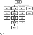
- Fig. 2 shows a schematic flow diagram illustrating embodiments of the method according to the fourth aspect of the present invention.
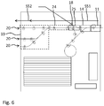
- Fig. 3 to Fig. 6 illustrate various functions of the paper path structure 10 as well as several variants, or ways to utilize, the method according to the fourth aspect of the present invention.
- a sheet of paper is received by the input path section 11.
- the orientation, which a front side of the received sheet of paper has when it is received by the input path section 11 will be called the "original orientation" in the following.
- the original orientation is face-up and the reversed orientation would be face-down.
- a step S21 the sheet of paper received via the input path section 11 is transported via the input path section 11, the switch 14, the second path section 22 and the first path section 21 to the flipping device.
- a step S22 the sheet of paper is flipped by the flipping device 15.
- a step S23 the flipped sheet of paper is deposited, by the flipping device 15, into the stack repository 16 with the reversed orientation.
- a sheet of paper received by the input path section 11 is to be stacked with its original orientation maintained, the following steps are performed: In a step S31, the sheet of paper is transported via the first path section 11, the switch 14, the fifth path section 25 and the third fork 18 to the fourth path section 24, preferably in a straight line.
- a direction of transporting of the sheet of paper is reversed by the fourth path section 24.
- step S33 the sheet of paper is transported via the fourth path section 24, the first and second branches of the third fork 18, the third path section 23, the third and first branches of the second fork 17 and the first path section 21 to the flipping device 15.
- step S34 the sheet of paper is flipped for a first time by a curvature of the third path section 23 and arrives flipped at the flipping device 15.
- step S34 the sheet of paper received from the third path section 23 is flipped for a second time by the flipping device 15 and is then, in a step S35, deposited by the flipping device 15 in the stack repository 16 such that the sheet of paper is stacked in the stack repository 16 with its original orientation (by virtue of being flipped twice).
- Steps S31 to S35 are illustrated in Fig. 4 .
- a sheet of paper is to be passed through the paper path structure 10 so as to have a reversed orientation
- the following steps may be performed:
- the received sheet of paper is transported via the input path section 11, the switch 14, the second path section 22, the second fork 17 to the first path section 21.
- a direction of transporting of the sheet of paper is reversed by the first path section 21.
- a step S43 the sheet of paper is transported via the first path section 21, the second fork 17, a third path section 23, whereby the sheet of paper is flipped due to the curvature of the third path section 23, and the third fork 18 to the fourth path section 24 and from the fourth path section 24 to the output path section 19.
- a step S44 the sheet of paper is output by the output path section 19.
- a sheet of paper is to be passed through the paper path structure 10 with its original orientation maintained, the following steps may be performed: In a step S51, the received sheet of paper is transported via the input path section 11, the switch 14, a fifth path section 25, the third fork 18 and the fourth path section 24 to the output path section 19.
- a sheet of paper is output by the output path section 19.
- Steps S51 and S52 are illustrated in Fig. 6 .
- the third path section is curved in such a way as to flip sheets of paper, and the second path section is arranged as a straight line
- the third path section is arranged as a straight line and the second path section is arranged with a curvature such as to flip sheets of paper being transported by the second path section, and the directions of the forks 14, 17, 18 of the triangle structure formed by the second, third and fifth path sections may be arranged correspondingly.
- a paper path structure is provided that is able to perform the following four functions: pass a sheet of paper through the paper path structure with is original orientation maintained; pass a sheet of paper through the paper path structure with its original orientation reversed; stack a sheet of paper in a stack repository with its original orientation maintained; and stack a sheet of paper in the stack repository with its original orientation reversed.
Landscapes
- Engineering & Computer Science (AREA)
- Mechanical Engineering (AREA)
- Separation, Sorting, Adjustment, Or Bending Of Sheets To Be Conveyed (AREA)
Claims (14)
- Papierpfadstruktur (10) mit:einem Eingabepfadabschnitt (11) zum Empfang von Bögen von Papier in der Papierpfadstruktur (10);einem Ausgabepfadabschnitt (19) zur Ausgabe von Bögen aus Papier aus der Papierpfadstruktur (10);einem Stapelspeicher (16) zur Aufnahme eines Stapels von Papierbögen;einer Wendeeinrichtung (15), die dazu konfiguriert ist, Papierbögen in dem Stapelspeicher (16) abzulegen;einem ersten Pfadabschnitt (21), der dazu steuerbar ist, Papierbögen zu der Wendeeinrichtung (15) zu transportieren;einem zweiten Pfadabschnitt (22), der mit dem Eingabepfadabschnitt (11) verbunden und dazu konfiguriert ist, Papierbögen in den ersten Pfadabschnitt (21) zu transportieren;einem dritten Pfadabschnitt (23), der dazu steuerbar ist, einen Papierbogen unabhängig von dem Eingabepfadabschnitt (11) in den ersten Pfadabschnitt (21) zu transportieren;wobei der erste Pfadabschnitt (21) auch dazu steuerbar ist, Papierbögen zu dem dritten Pfadabschnitt (23) zu transportieren, und wobei der dritte Pfadabschnitt (23) auch dazu steuerbar ist, Papierbögen aus dem ersten Pfadabschnitt (21) zu empfangen und den empfangenen Papierbogen von dem ersten Pfadabschnitt (21) weg zu transportieren,dadurch gekennzeichnet, dass die Papierpfadstruktur (10) dazu konfiguriert ist:a) einen Bogen aus dem Eingabepfadabschnitt (11) über den zweiten Pfadabschnitt (22) zu der Wendeeinrichtung (15) zu transportieren, derart, dass der Bogen in einer Orientierung gestapelt wird, die umgekehrt ist in Bezug auf die Orientierung des Bogens in dem Eingabepfadabschnitt (11);b) einen Bogen aus dem Eingabepfadabschnitt (11) nacheinander über die zweiten und dritten Pfadabschnitte zu dem Ausgabepfadabschnitt zu transportieren, derart, dass der Bogen zu dem Ausgabepfadabschnitt in einer Orientierung ausgegeben wird, in Bezug auf die Orientierung des Bogens in dem Eingabepfadabschnitt (11) umgekehrt ist:c) einen Bogen aus dem Eingabepfadabschnitt (11) über einen fünften Papierpfadabschnitt (25), der die zweiten und dritten Papierpfadabschnitte (22, 23) umgeht, derart zu dem Ausgabepfadabschnitt (19) zu transportieren, dass der Bogen in der gleichen Orientierung in Bezug auf die Orientierung dieses Bogens auf dem Eingabepfadabschnitt (11) in den Ausgabepfadabschnitt (19) ausgegeben wird; undd) einen Bogen aus dem Eingabepfadabschnitt (11) nacheinander über die fünften und dritten Papierpfadabschnitte (23, 25) zu der Wendeeinrichtung (15) zu transportieren, derart, dass dieser Bogen in derselben Orientierung in Bezug auf die Orientierung dieses Bogens auf dem Eingabepfadabschnitt (11) gestapelt wird.
- Papierpfadstruktur (10) nach Anspruch 1,
mit einem vierten Pfadabschnitt (24), der dazu steuerbar ist, Papierbögen zu dem dritten Pfadabschnitt (23) zu transportieren;
wobei der vierte Pfadabschnitt (24) auch dazu steuerbar ist, Papierbögen aus dem dritten Pfadabschnitt (23) zu empfangen und die empfangenen Papierbögen zu dem Ausgabepfadabschnitt (19) zu transportieren. - Papierpfadstruktur (10) nach Anspruch 1 oder 2,
mit einem fünften Pfadabschnitt (25), der mit dem Eingabepfadabschnitt (11) verbunden ist und dazu konfiguriert ist, Papierbögen von dem Eingabepfadabschnitt (11) weg zu transportieren; und
einer Weiche, die an einem Ende des ersten Pfadabschnitts (21) angeordnet ist und die dazu steuerbar ist, Papierbögen aus dem Eingabepfadabschnitt (11) in den ersten Pfadabschnitt (21) oder in den fünften Pfadabschnitt (25) zu lenken. - Papierpfadstruktur (10) nach Ansprüchen 2 und 3,
bei der der fünfte Pfadabschnitt (25) dazu konfiguriert ist, Papierbögen unabhängig von den zweiten und dritten Pfadabschnitten (22, 23) zu dem vierten Pfadabschnitt (24) zu transportieren. - Papierpfadstruktur (10) nach Anspruch 3 oder 4,
bei der der zweite Pfadabschnitt (22), der dritte Pfadabschnitt (23) und der fünfte Pfadabschnitt (25) eine dreieckige Figur bilden. - Struktur nach Anspruch 5,
bei der die dreieckige Figur zwei Gabeln (17, 18) mit je drei Ästen aufweist, wobei jede der beiden Gabeln (17, 18) es erlaubt, Papierbögen von zwei Ästen der Gabel (17, 18) in einen dritten Ast der Gabel zu transportieren aber es Bögen aus dem dritten Ast der Gabel (17, 18) nur erlaubt, in einen der beiden anderen Äste der Gabel (17, 18) transportiert zu werden. - Papierpfadstruktur (10) nach einem der Ansprüche 1 bis 6,
mit einer Bogenregistriereinheit (12), die an dem Eingabepfadabschnitt (11) angeordnet ist und die dazu konfiguriert ist, eine Eigenschaft der Papierbögen zu bestimmen, die in dem Eingabepfadabschnitt (11) empfangen wurden, wobei eine Steuerung der Pfadabschnitte der Papierpfadstruktur (10) für jeden empfangenen Papierbogen von den bestimmten Eigenschaften dieses empfangenen Papierbogens abhängt. - Papierpfadstruktur (10) nach einem der Ansprüche 1 bis 7,
bei der der Ausgabepfadabschnitt (19) mehrere Papierauslässe (20) aufweist und dazu steuerbar ist, Papierbögen, die von dem Ausgabepfadabschnitt (19) empfangen wurden, zu irgendeinem der mehreren Papierauslässe (20) zu lenken. - Stapler (100) mit einer Papierpfadstruktur (10) nach einem der Ansprüche 1 bis 8.
- Drucker mit einer Papierpfadstruktur (10) nach einem der Ansprüche 1 bis 8.
- Verfahren zum Betreiben einer Papierpfadstruktur (10) gemäß einem der Ansprüche 1 bis 8, mit Empfang (S10), in dem Eingabepfadabschnitt (11), eines Papierbogens, der eine ursprüngliche Orientierung seiner Vorderseite in die Papierpfadstruktur (10) hat; und
wobei, wenn ein Papierbogen in einer umgekehrten Orientierung gestapelt werden soll, die folgenden Schritte ausgeführt werden:transportieren (S21) des Papierbogens über den Eingabepfadabschnitt (11), den zweiten Pfadabschnitt (22) und den ersten Pfadabschnitt (21) zu der Wendeeinrichtung (15);wenden (S22), des Papierbogens mit Hilfe der Wendeeinrichtung (15); undablegen (S23), mit der Wendeeinrichtung (15), des Papierbogens in dem Stapelspeicher (16), derart, dass der Bogen mit umgekehrter Orientierung gestapelt wird,gekennzeichnet durch die folgenden Schritte:a) transportieren eines Bogens aus dem Eingabepfadabschnitt (11) über den zweiten Papierpfadabschnitt (22) zu der Wendeeinrichtung (15) derart, dass der Bogen in einer Orientierung gestapelt wird, die in Bezug auf die Orientierung dieses Bogens in dem Eingabepfadabschnitt (11) umgekehrt ist;b) transportieren eines Bogens aus dem Eingabepfadabschnitt (11) nacheinander über die zweiten und dritten Papierpfadabschnitte (22, 23) zu dem Ausgabepfadabschnitt (19) derart, dass dieser Bogen in den Ausgabepfadabschnitt (19) in einer Orientierung ausgegeben wird, die in Bezug auf die Orientierung dieses Bogens in dem Eingabepfadabschnitt (11) umgekehrt ist;c) transportieren eines Bogens aus dem Eingabepfadabschnitt (11) über einen fünften Papierpfadabschnitt (25), der die zweiten und dritten Papierpfadabschnitte (22, 23) umgeht, zu dem Ausgabepfadabschnitt (19) derart, dass dieser Bogen in den Ausgabepfadabschnitt (19) in derselben Orientierung in Bezug auf die Orientierung dieses Bogens in den Eingabepfadabschnitt ausgegeben wird; undd) transportieren eines Bogens aus dem Eingabepfadabschnitt (11) nacheinander über die fünften und dritten Papierpfadabschnitte (23, 25) zu der Wendeeinrichtung (15) derart, dass dieser Bogen in derselben Orientierung in Bezug auf die Orientierung dieses Bogens in dem Eingabepfadabschnitt (11) gestapelt wird. - Verfahren nach Anspruch 11,
bei dem, wenn ein Papierbogen unter Beibehaltung seiner ursprünglichen Orientierung gestapelt werden soll, die folgenden Schritte ausgeführt werden:transportieren (S31), des Papierbogens über den ersten Pfadabschnitt (21) und den fünften Pfadabschnitt (25) zu dem vierten Pfadabschnitt (24);umkehren (S32) der Transportrichtung des Papierbogens in dem vierten Pfadabschnitt (24);transportieren (S33) des Papierbogens über den vierten Pfadabschnitt (24), den dritten Pfadabschnitt (23) und den ersten Pfadabschnitt (21) zu der Wendeeinrichtung (15), wobei der Papierbogen, indem er den dritten Pfadabschnitt (23) durchläuft, zum ersten Mal gewendet wird;wenden (S34) des Papierbogens ein zweites Mal mit der Wendeeinrichtung (15); undablegen (S35), mit der Wendeeinrichtung (15), des Papierbogens in dem Stapelspeicher (16) derart, dass der Papierbogen mit seiner ursprünglichen Orientierung gestapelt wird. - Verfahren nach Anspruch 11 oder 12,
bei dem, wenn ein Papierbogen so durch die Papierpfadstruktur (10) laufen soll, dass er eine umgekehrte Orientierung hat, die folgenden Schritte ausgeführt werden:transportieren (S41) des Papierbogens über den Eingabepfadabschnitt (11) und den zweiten Pfadabschnitt (22) zu dem ersten Pfadabschnitt (21);umkehren (S42) der Transportrichtung des Papierbogens in dem ersten Pfadabschnitt (21);transportieren (S43) des Papierbogens über den ersten Pfadabschnitt (21), den dritten Pfadabschnitt (23), wodurch der Papierbogen gewendet wird, und den vierten Pfadabschnitt (24) zu dem Ausgabepfadabschnitt (19); undausgeben (S44) des Papierbogens durch den Ausgabepfadabschnitt (19). - Verfahren nach einem der Ansprüche 11 bis 13,
bei dem, wenn ein Papierbogen unter Beibehaltung seiner ursprünglichen Orientierung durch die Papierpfadstruktur (10) laufen soll, die folgenden Schritte ausgeführt werden:transportieren (S51) des Papierbogens über den Eingabepfadabschnitt (11), den fünften Pfadabschnitt (25) und den vierten Pfadabschnitt (24) zu dem Ausgabepfadabschnitt (19); undausgeben (S52) des Papierbogens durch den Ausgabepfadabschnitt (19).
Priority Applications (2)
| Application Number | Priority Date | Filing Date | Title |
|---|---|---|---|
| EP18181318.9A EP3590876B1 (de) | 2018-07-03 | 2018-07-03 | Papierpfadstruktur, stapler, drucker und verfahren zum betrieb einer papierpfadstruktur |
| US16/452,241 US11192739B2 (en) | 2018-07-03 | 2019-06-25 | Paper path structure, stacker, printer and method for operating a paper path structure |
Applications Claiming Priority (1)
| Application Number | Priority Date | Filing Date | Title |
|---|---|---|---|
| EP18181318.9A EP3590876B1 (de) | 2018-07-03 | 2018-07-03 | Papierpfadstruktur, stapler, drucker und verfahren zum betrieb einer papierpfadstruktur |
Publications (3)
| Publication Number | Publication Date |
|---|---|
| EP3590876A1 EP3590876A1 (de) | 2020-01-08 |
| EP3590876A8 EP3590876A8 (de) | 2020-03-11 |
| EP3590876B1 true EP3590876B1 (de) | 2021-03-31 |
Family
ID=62846007
Family Applications (1)
| Application Number | Title | Priority Date | Filing Date |
|---|---|---|---|
| EP18181318.9A Active EP3590876B1 (de) | 2018-07-03 | 2018-07-03 | Papierpfadstruktur, stapler, drucker und verfahren zum betrieb einer papierpfadstruktur |
Country Status (2)
| Country | Link |
|---|---|
| US (1) | US11192739B2 (de) |
| EP (1) | EP3590876B1 (de) |
Families Citing this family (1)
| Publication number | Priority date | Publication date | Assignee | Title |
|---|---|---|---|---|
| CN111546414B (zh) * | 2020-06-03 | 2021-11-30 | 聊城市瀚格智能科技有限公司 | 一种瓦楞纸板裁切后自动化码垛机械及码垛方法 |
Family Cites Families (13)
| Publication number | Priority date | Publication date | Assignee | Title |
|---|---|---|---|---|
| JPH0662237B2 (ja) * | 1985-04-12 | 1994-08-17 | ゼロツクス コーポレーシヨン | シートスタツク装置 |
| US5852764A (en) * | 1996-05-14 | 1998-12-22 | Sharp Kabushiki Kaisha | Sheet post-processing apparatus |
| FR2760733B1 (fr) * | 1997-03-12 | 1999-05-07 | C P Bourg Sa | Machine d'empilage de feuilles |
| DE60120328T2 (de) | 2000-12-05 | 2007-05-10 | Xerox Corp. | Blattwendesystem |
| US6419222B1 (en) * | 2000-12-12 | 2002-07-16 | Xerox Corporation | Sheet inverting apparatus and method |
| US6883800B2 (en) * | 2003-02-20 | 2005-04-26 | Kabushiki Kaisha Toshiba | Paper convey method and device in image forming apparatus |
| US20050280198A1 (en) * | 2004-06-21 | 2005-12-22 | Eastman Kodak Company | Devices and methods for flipping a sheet with blowing assistance |
| US7566055B2 (en) * | 2004-09-03 | 2009-07-28 | Xerox Corporation | Substrate inverter systems and methods |
| JP4731983B2 (ja) * | 2005-05-06 | 2011-07-27 | キヤノン株式会社 | シート表裏反転搬送装置と該装置を備えた画像形成装置 |
| US20080265501A1 (en) * | 2007-04-26 | 2008-10-30 | Foote Wayne E | Preflipping sheets for a duplex operation |
| US7631859B2 (en) * | 2007-10-01 | 2009-12-15 | Xerox Corporation | Dual disc stacker/stitcher high speed finisher |
| US20100042252A1 (en) * | 2008-08-13 | 2010-02-18 | Xerox Corporation | Disk type apparatus and corresponding methods |
| US8748769B2 (en) * | 2012-10-24 | 2014-06-10 | Pitney Bowes Inc. | Stacking assembly for a mailpiece sorter |
-
2018
- 2018-07-03 EP EP18181318.9A patent/EP3590876B1/de active Active
-
2019
- 2019-06-25 US US16/452,241 patent/US11192739B2/en active Active
Non-Patent Citations (1)
| Title |
|---|
| None * |
Also Published As
| Publication number | Publication date |
|---|---|
| US20200010298A1 (en) | 2020-01-09 |
| EP3590876A8 (de) | 2020-03-11 |
| EP3590876A1 (de) | 2020-01-08 |
| US11192739B2 (en) | 2021-12-07 |
Similar Documents
| Publication | Publication Date | Title |
|---|---|---|
| JP4629447B2 (ja) | 印刷システム、及び印刷システム動作方法 | |
| EP1921036B1 (de) | Drehtransportvorrichtung für Druckmedien | |
| JP2006056717A (ja) | 媒体の速度のバッファ及びレジストレーション機能を有する反転器をもつ印刷システム | |
| JP2010285244A (ja) | 姿勢変換装置、および紙葉類処理装置 | |
| JP2015096447A (ja) | 画像形成装置 | |
| US20020085853A1 (en) | Techniques for achieving correct order in printer output | |
| JP2007176702A5 (de) | ||
| US11192739B2 (en) | Paper path structure, stacker, printer and method for operating a paper path structure | |
| US4317563A (en) | Blowing device in sheet deliverers of sheet processing machines | |
| JP4175642B2 (ja) | 紙折り装置 | |
| TW200920673A (en) | Levitation transportation system | |
| JP2020050510A (ja) | 媒体搬送装置、媒体処理装置、及び記録システム | |
| US7699308B2 (en) | Apparatus for diverting sheet material | |
| JP2002220150A (ja) | 2つの交替式シート反転装置を備える高速プリンタ | |
| JP2020050502A (ja) | 媒体搬送装置、媒体処理装置、及び記録システム | |
| US6971647B2 (en) | Media registration mechanism for image forming device | |
| JP5439105B2 (ja) | 紙葉類表裏取揃装置 | |
| JP2016118773A5 (de) | ||
| US10604373B2 (en) | Recording system | |
| JP6931183B2 (ja) | 記録システム | |
| JP7198634B2 (ja) | 枚葉類表裏反転機構、枚葉類処理装置、および現金取扱い装置 | |
| JP2002249214A (ja) | ベルトコンベヤの中折れ機構 | |
| JP6705421B2 (ja) | 画像形成装置 | |
| KR20230102784A (ko) | 금융자동화기기 | |
| JP4989550B2 (ja) | 定尺ベニヤ単板の堆積方法 |
Legal Events
| Date | Code | Title | Description |
|---|---|---|---|
| PUAI | Public reference made under article 153(3) epc to a published international application that has entered the european phase |
Free format text: ORIGINAL CODE: 0009012 |
|
| STAA | Information on the status of an ep patent application or granted ep patent |
Free format text: STATUS: THE APPLICATION HAS BEEN PUBLISHED |
|
| AK | Designated contracting states |
Kind code of ref document: A1 Designated state(s): AL AT BE BG CH CY CZ DE DK EE ES FI FR GB GR HR HU IE IS IT LI LT LU LV MC MK MT NL NO PL PT RO RS SE SI SK SM TR |
|
| AX | Request for extension of the european patent |
Extension state: BA ME |
|
| RIN1 | Information on inventor provided before grant (corrected) |
Inventor name: LA VOS, PETER G. Inventor name: EIJSSEN, JACOBUS M.G. Inventor name: PRINSEN, KEVIN H.J.R. Inventor name: VAN DE SANDE, HENRICUS J.A. |
|
| RAP1 | Party data changed (applicant data changed or rights of an application transferred) |
Owner name: CANON PRODUCTION PRINTING HOLDING B.V. |
|
| STAA | Information on the status of an ep patent application or granted ep patent |
Free format text: STATUS: REQUEST FOR EXAMINATION WAS MADE |
|
| 17P | Request for examination filed |
Effective date: 20200708 |
|
| RBV | Designated contracting states (corrected) |
Designated state(s): AL AT BE BG CH CY CZ DE DK EE ES FI FR GB GR HR HU IE IS IT LI LT LU LV MC MK MT NL NO PL PT RO RS SE SI SK SM TR |
|
| GRAP | Despatch of communication of intention to grant a patent |
Free format text: ORIGINAL CODE: EPIDOSNIGR1 |
|
| STAA | Information on the status of an ep patent application or granted ep patent |
Free format text: STATUS: GRANT OF PATENT IS INTENDED |
|
| INTG | Intention to grant announced |
Effective date: 20201028 |
|
| RAP1 | Party data changed (applicant data changed or rights of an application transferred) |
Owner name: CANON PRODUCTION PRINTING HOLDING B.V. |
|
| GRAS | Grant fee paid |
Free format text: ORIGINAL CODE: EPIDOSNIGR3 |
|
| GRAA | (expected) grant |
Free format text: ORIGINAL CODE: 0009210 |
|
| STAA | Information on the status of an ep patent application or granted ep patent |
Free format text: STATUS: THE PATENT HAS BEEN GRANTED |
|
| AK | Designated contracting states |
Kind code of ref document: B1 Designated state(s): AL AT BE BG CH CY CZ DE DK EE ES FI FR GB GR HR HU IE IS IT LI LT LU LV MC MK MT NL NO PL PT RO RS SE SI SK SM TR |
|
| REG | Reference to a national code |
Ref country code: GB Ref legal event code: FG4D Ref country code: CH Ref legal event code: EP |
|
| REG | Reference to a national code |
Ref country code: DE Ref legal event code: R096 Ref document number: 602018014612 Country of ref document: DE Ref country code: AT Ref legal event code: REF Ref document number: 1376724 Country of ref document: AT Kind code of ref document: T Effective date: 20210415 |
|
| REG | Reference to a national code |
Ref country code: IE Ref legal event code: FG4D |
|
| REG | Reference to a national code |
Ref country code: NL Ref legal event code: FP |
|
| REG | Reference to a national code |
Ref country code: LT Ref legal event code: MG9D |
|
| PG25 | Lapsed in a contracting state [announced via postgrant information from national office to epo] |
Ref country code: BG Free format text: LAPSE BECAUSE OF FAILURE TO SUBMIT A TRANSLATION OF THE DESCRIPTION OR TO PAY THE FEE WITHIN THE PRESCRIBED TIME-LIMIT Effective date: 20210630 Ref country code: HR Free format text: LAPSE BECAUSE OF FAILURE TO SUBMIT A TRANSLATION OF THE DESCRIPTION OR TO PAY THE FEE WITHIN THE PRESCRIBED TIME-LIMIT Effective date: 20210331 Ref country code: FI Free format text: LAPSE BECAUSE OF FAILURE TO SUBMIT A TRANSLATION OF THE DESCRIPTION OR TO PAY THE FEE WITHIN THE PRESCRIBED TIME-LIMIT Effective date: 20210331 Ref country code: NO Free format text: LAPSE BECAUSE OF FAILURE TO SUBMIT A TRANSLATION OF THE DESCRIPTION OR TO PAY THE FEE WITHIN THE PRESCRIBED TIME-LIMIT Effective date: 20210630 |
|
| PG25 | Lapsed in a contracting state [announced via postgrant information from national office to epo] |
Ref country code: LV Free format text: LAPSE BECAUSE OF FAILURE TO SUBMIT A TRANSLATION OF THE DESCRIPTION OR TO PAY THE FEE WITHIN THE PRESCRIBED TIME-LIMIT Effective date: 20210331 Ref country code: RS Free format text: LAPSE BECAUSE OF FAILURE TO SUBMIT A TRANSLATION OF THE DESCRIPTION OR TO PAY THE FEE WITHIN THE PRESCRIBED TIME-LIMIT Effective date: 20210331 Ref country code: SE Free format text: LAPSE BECAUSE OF FAILURE TO SUBMIT A TRANSLATION OF THE DESCRIPTION OR TO PAY THE FEE WITHIN THE PRESCRIBED TIME-LIMIT Effective date: 20210331 |
|
| REG | Reference to a national code |
Ref country code: AT Ref legal event code: MK05 Ref document number: 1376724 Country of ref document: AT Kind code of ref document: T Effective date: 20210331 |
|
| PG25 | Lapsed in a contracting state [announced via postgrant information from national office to epo] |
Ref country code: LT Free format text: LAPSE BECAUSE OF FAILURE TO SUBMIT A TRANSLATION OF THE DESCRIPTION OR TO PAY THE FEE WITHIN THE PRESCRIBED TIME-LIMIT Effective date: 20210331 Ref country code: EE Free format text: LAPSE BECAUSE OF FAILURE TO SUBMIT A TRANSLATION OF THE DESCRIPTION OR TO PAY THE FEE WITHIN THE PRESCRIBED TIME-LIMIT Effective date: 20210331 Ref country code: CZ Free format text: LAPSE BECAUSE OF FAILURE TO SUBMIT A TRANSLATION OF THE DESCRIPTION OR TO PAY THE FEE WITHIN THE PRESCRIBED TIME-LIMIT Effective date: 20210331 Ref country code: AT Free format text: LAPSE BECAUSE OF FAILURE TO SUBMIT A TRANSLATION OF THE DESCRIPTION OR TO PAY THE FEE WITHIN THE PRESCRIBED TIME-LIMIT Effective date: 20210331 Ref country code: SM Free format text: LAPSE BECAUSE OF FAILURE TO SUBMIT A TRANSLATION OF THE DESCRIPTION OR TO PAY THE FEE WITHIN THE PRESCRIBED TIME-LIMIT Effective date: 20210331 |
|
| PG25 | Lapsed in a contracting state [announced via postgrant information from national office to epo] |
Ref country code: IS Free format text: LAPSE BECAUSE OF FAILURE TO SUBMIT A TRANSLATION OF THE DESCRIPTION OR TO PAY THE FEE WITHIN THE PRESCRIBED TIME-LIMIT Effective date: 20210731 Ref country code: PL Free format text: LAPSE BECAUSE OF FAILURE TO SUBMIT A TRANSLATION OF THE DESCRIPTION OR TO PAY THE FEE WITHIN THE PRESCRIBED TIME-LIMIT Effective date: 20210331 Ref country code: PT Free format text: LAPSE BECAUSE OF FAILURE TO SUBMIT A TRANSLATION OF THE DESCRIPTION OR TO PAY THE FEE WITHIN THE PRESCRIBED TIME-LIMIT Effective date: 20210802 Ref country code: RO Free format text: LAPSE BECAUSE OF FAILURE TO SUBMIT A TRANSLATION OF THE DESCRIPTION OR TO PAY THE FEE WITHIN THE PRESCRIBED TIME-LIMIT Effective date: 20210331 Ref country code: SK Free format text: LAPSE BECAUSE OF FAILURE TO SUBMIT A TRANSLATION OF THE DESCRIPTION OR TO PAY THE FEE WITHIN THE PRESCRIBED TIME-LIMIT Effective date: 20210331 |
|
| REG | Reference to a national code |
Ref country code: DE Ref legal event code: R097 Ref document number: 602018014612 Country of ref document: DE |
|
| PG25 | Lapsed in a contracting state [announced via postgrant information from national office to epo] |
Ref country code: ES Free format text: LAPSE BECAUSE OF FAILURE TO SUBMIT A TRANSLATION OF THE DESCRIPTION OR TO PAY THE FEE WITHIN THE PRESCRIBED TIME-LIMIT Effective date: 20210331 Ref country code: AL Free format text: LAPSE BECAUSE OF FAILURE TO SUBMIT A TRANSLATION OF THE DESCRIPTION OR TO PAY THE FEE WITHIN THE PRESCRIBED TIME-LIMIT Effective date: 20210331 Ref country code: DK Free format text: LAPSE BECAUSE OF FAILURE TO SUBMIT A TRANSLATION OF THE DESCRIPTION OR TO PAY THE FEE WITHIN THE PRESCRIBED TIME-LIMIT Effective date: 20210331 |
|
| PLBE | No opposition filed within time limit |
Free format text: ORIGINAL CODE: 0009261 |
|
| STAA | Information on the status of an ep patent application or granted ep patent |
Free format text: STATUS: NO OPPOSITION FILED WITHIN TIME LIMIT |
|
| REG | Reference to a national code |
Ref country code: CH Ref legal event code: PL |
|
| 26N | No opposition filed |
Effective date: 20220104 |
|
| PG25 | Lapsed in a contracting state [announced via postgrant information from national office to epo] |
Ref country code: MC Free format text: LAPSE BECAUSE OF FAILURE TO SUBMIT A TRANSLATION OF THE DESCRIPTION OR TO PAY THE FEE WITHIN THE PRESCRIBED TIME-LIMIT Effective date: 20210331 |
|
| REG | Reference to a national code |
Ref country code: BE Ref legal event code: MM Effective date: 20210731 |
|
| PG25 | Lapsed in a contracting state [announced via postgrant information from national office to epo] |
Ref country code: LI Free format text: LAPSE BECAUSE OF NON-PAYMENT OF DUE FEES Effective date: 20210731 Ref country code: CH Free format text: LAPSE BECAUSE OF NON-PAYMENT OF DUE FEES Effective date: 20210731 |
|
| PG25 | Lapsed in a contracting state [announced via postgrant information from national office to epo] |
Ref country code: IS Free format text: LAPSE BECAUSE OF FAILURE TO SUBMIT A TRANSLATION OF THE DESCRIPTION OR TO PAY THE FEE WITHIN THE PRESCRIBED TIME-LIMIT Effective date: 20210731 Ref country code: LU Free format text: LAPSE BECAUSE OF NON-PAYMENT OF DUE FEES Effective date: 20210703 Ref country code: FR Free format text: LAPSE BECAUSE OF NON-PAYMENT OF DUE FEES Effective date: 20210731 |
|
| PG25 | Lapsed in a contracting state [announced via postgrant information from national office to epo] |
Ref country code: IT Free format text: LAPSE BECAUSE OF FAILURE TO SUBMIT A TRANSLATION OF THE DESCRIPTION OR TO PAY THE FEE WITHIN THE PRESCRIBED TIME-LIMIT Effective date: 20210331 Ref country code: IE Free format text: LAPSE BECAUSE OF NON-PAYMENT OF DUE FEES Effective date: 20210703 Ref country code: BE Free format text: LAPSE BECAUSE OF NON-PAYMENT OF DUE FEES Effective date: 20210731 |
|
| GBPC | Gb: european patent ceased through non-payment of renewal fee |
Effective date: 20220703 |
|
| PG25 | Lapsed in a contracting state [announced via postgrant information from national office to epo] |
Ref country code: GB Free format text: LAPSE BECAUSE OF NON-PAYMENT OF DUE FEES Effective date: 20220703 |
|
| PG25 | Lapsed in a contracting state [announced via postgrant information from national office to epo] |
Ref country code: CY Free format text: LAPSE BECAUSE OF FAILURE TO SUBMIT A TRANSLATION OF THE DESCRIPTION OR TO PAY THE FEE WITHIN THE PRESCRIBED TIME-LIMIT Effective date: 20210331 |
|
| PG25 | Lapsed in a contracting state [announced via postgrant information from national office to epo] |
Ref country code: HU Free format text: LAPSE BECAUSE OF FAILURE TO SUBMIT A TRANSLATION OF THE DESCRIPTION OR TO PAY THE FEE WITHIN THE PRESCRIBED TIME-LIMIT; INVALID AB INITIO Effective date: 20180703 Ref country code: GR Free format text: LAPSE BECAUSE OF FAILURE TO SUBMIT A TRANSLATION OF THE DESCRIPTION OR TO PAY THE FEE WITHIN THE PRESCRIBED TIME-LIMIT Effective date: 20210331 |
|
| PG25 | Lapsed in a contracting state [announced via postgrant information from national office to epo] |
Ref country code: MK Free format text: LAPSE BECAUSE OF FAILURE TO SUBMIT A TRANSLATION OF THE DESCRIPTION OR TO PAY THE FEE WITHIN THE PRESCRIBED TIME-LIMIT Effective date: 20210331 |
|
| PG25 | Lapsed in a contracting state [announced via postgrant information from national office to epo] |
Ref country code: TR Free format text: LAPSE BECAUSE OF FAILURE TO SUBMIT A TRANSLATION OF THE DESCRIPTION OR TO PAY THE FEE WITHIN THE PRESCRIBED TIME-LIMIT Effective date: 20210331 |
|
| PG25 | Lapsed in a contracting state [announced via postgrant information from national office to epo] |
Ref country code: MT Free format text: LAPSE BECAUSE OF FAILURE TO SUBMIT A TRANSLATION OF THE DESCRIPTION OR TO PAY THE FEE WITHIN THE PRESCRIBED TIME-LIMIT Effective date: 20210331 |
|
| PGFP | Annual fee paid to national office [announced via postgrant information from national office to epo] |
Ref country code: DE Payment date: 20250722 Year of fee payment: 8 |
|
| PGFP | Annual fee paid to national office [announced via postgrant information from national office to epo] |
Ref country code: NL Payment date: 20260618 Year of fee payment: 9 |