EP3590884B1 - Zapfpistole zur betankung - Google Patents
Zapfpistole zur betankung Download PDFInfo
- Publication number
- EP3590884B1 EP3590884B1 EP17898603.0A EP17898603A EP3590884B1 EP 3590884 B1 EP3590884 B1 EP 3590884B1 EP 17898603 A EP17898603 A EP 17898603A EP 3590884 B1 EP3590884 B1 EP 3590884B1
- Authority
- EP
- European Patent Office
- Prior art keywords
- fueling
- discharge pipe
- grip
- oil
- main body
- Prior art date
- Legal status (The legal status is an assumption and is not a legal conclusion. Google has not performed a legal analysis and makes no representation as to the accuracy of the status listed.)
- Active
Links
Images



Classifications
-
- B—PERFORMING OPERATIONS; TRANSPORTING
- B67—OPENING, CLOSING OR CLEANING BOTTLES, JARS OR SIMILAR CONTAINERS; LIQUID HANDLING
- B67D—DISPENSING, DELIVERING OR TRANSFERRING LIQUIDS, NOT OTHERWISE PROVIDED FOR
- B67D7/00—Apparatus or devices for transferring liquids from bulk storage containers or reservoirs into vehicles or into portable containers, e.g. for retail sale purposes
- B67D7/06—Details or accessories
- B67D7/32—Arrangements of safety or warning devices; Means for preventing unauthorised delivery of liquid
- B67D7/34—Means for preventing unauthorised delivery of liquid
-
- B—PERFORMING OPERATIONS; TRANSPORTING
- B67—OPENING, CLOSING OR CLEANING BOTTLES, JARS OR SIMILAR CONTAINERS; LIQUID HANDLING
- B67D—DISPENSING, DELIVERING OR TRANSFERRING LIQUIDS, NOT OTHERWISE PROVIDED FOR
- B67D7/00—Apparatus or devices for transferring liquids from bulk storage containers or reservoirs into vehicles or into portable containers, e.g. for retail sale purposes
- B67D7/04—Apparatus or devices for transferring liquids from bulk storage containers or reservoirs into vehicles or into portable containers, e.g. for retail sale purposes for transferring fuels, lubricants or mixed fuels and lubricants
-
- B—PERFORMING OPERATIONS; TRANSPORTING
- B67—OPENING, CLOSING OR CLEANING BOTTLES, JARS OR SIMILAR CONTAINERS; LIQUID HANDLING
- B67D—DISPENSING, DELIVERING OR TRANSFERRING LIQUIDS, NOT OTHERWISE PROVIDED FOR
- B67D7/00—Apparatus or devices for transferring liquids from bulk storage containers or reservoirs into vehicles or into portable containers, e.g. for retail sale purposes
- B67D7/06—Details or accessories
- B67D7/32—Arrangements of safety or warning devices; Means for preventing unauthorised delivery of liquid
- B67D7/3218—Arrangements of safety or warning devices; Means for preventing unauthorised delivery of liquid relating to emergency shut-off means
-
- B—PERFORMING OPERATIONS; TRANSPORTING
- B67—OPENING, CLOSING OR CLEANING BOTTLES, JARS OR SIMILAR CONTAINERS; LIQUID HANDLING
- B67D—DISPENSING, DELIVERING OR TRANSFERRING LIQUIDS, NOT OTHERWISE PROVIDED FOR
- B67D7/00—Apparatus or devices for transferring liquids from bulk storage containers or reservoirs into vehicles or into portable containers, e.g. for retail sale purposes
- B67D7/06—Details or accessories
- B67D7/42—Filling nozzles
-
- B—PERFORMING OPERATIONS; TRANSPORTING
- B67—OPENING, CLOSING OR CLEANING BOTTLES, JARS OR SIMILAR CONTAINERS; LIQUID HANDLING
- B67D—DISPENSING, DELIVERING OR TRANSFERRING LIQUIDS, NOT OTHERWISE PROVIDED FOR
- B67D7/00—Apparatus or devices for transferring liquids from bulk storage containers or reservoirs into vehicles or into portable containers, e.g. for retail sale purposes
- B67D7/06—Details or accessories
- B67D7/42—Filling nozzles
- B67D7/421—Filling nozzles comprising protective covers, e.g. anti-splash attachments
-
- B—PERFORMING OPERATIONS; TRANSPORTING
- B67—OPENING, CLOSING OR CLEANING BOTTLES, JARS OR SIMILAR CONTAINERS; LIQUID HANDLING
- B67D—DISPENSING, DELIVERING OR TRANSFERRING LIQUIDS, NOT OTHERWISE PROVIDED FOR
- B67D7/00—Apparatus or devices for transferring liquids from bulk storage containers or reservoirs into vehicles or into portable containers, e.g. for retail sale purposes
- B67D7/06—Details or accessories
- B67D7/32—Arrangements of safety or warning devices; Means for preventing unauthorised delivery of liquid
- B67D7/3236—Arrangements of safety or warning devices; Means for preventing unauthorised delivery of liquid relating to electrostatic charges
-
- B—PERFORMING OPERATIONS; TRANSPORTING
- B67—OPENING, CLOSING OR CLEANING BOTTLES, JARS OR SIMILAR CONTAINERS; LIQUID HANDLING
- B67D—DISPENSING, DELIVERING OR TRANSFERRING LIQUIDS, NOT OTHERWISE PROVIDED FOR
- B67D7/00—Apparatus or devices for transferring liquids from bulk storage containers or reservoirs into vehicles or into portable containers, e.g. for retail sale purposes
- B67D7/06—Details or accessories
- B67D7/42—Filling nozzles
- B67D7/44—Filling nozzles automatically closing
- B67D7/46—Filling nozzles automatically closing when liquid in container to be filled reaches a predetermined level
Definitions
- the present invention relates to a fueling nozzle used for suppling fuel oil to a fueling tank of a vehicle (hereinafter referred to as "in-vehicle tank”) or the like in a gas station and others.
- a fueling nozzle is mounted at an end of a fueling hose lead from a fueling apparatus of a gas station, and is hooked on a nozzle hook of the fueling apparatus when fueling is not carried out. Then, after an operator detaches the fueling nozzle from the nozzle hook to insert it into the vehicle tank or the like, a fueling mechanism of the fueling apparatus is driven to perform fuel oil supply.
- Patent document JP 2004 189246 A a fueling apparatus including a static electricity removal panel that removes static electricity charged to a customer by touching it before fueling operation.
- Fueling nozzles are known from JP 2004 189246 A , JP 2009 012833 A , JP 2007 153429 A and JP 2012 091838 A .
- the invention described in the above Patent document 1 is effective, and the static electricity removal panel can remove static electricity charged to a customer's body while the customer touches it, but there is a possibility that static electricity charges to the customer's body during operation of the fueling nozzle after the customer's hand moves away from the static electricity removal panel, so that there is room for improvement on the fueling nozzle.
- the present invention has been made in consideration of the above problems in the conventional technique, and the object of the present invention is to provide a safety fueling nozzle capable of certainly removing static electricity generated at fueling, that is, while the fueling nozzle is used.
- the present invention relates to a fueling nozzle according to the appended claims.
- the grip and the cover for covering the grip are made of conductive metal, and to the grip is connected the ground wire, so that static electricity charged to a customer's body during fueling operation can be removed through the grip, which enables safety fueling operation.
- fixing the conductive cover to an end portion of the grip on the fueling hose side or the main body side prevents the cover made of conductive metal from being removed from the grip. Further, fixing the conductive cover to an end portion of the grip on the fueling hose side and an end portion of the grip on the main body side prevents the cover made of conductive metal from rotating around the axis of the grip besides the prevention of detachment from the grip.
- the conductive cover may include a cutout extending in an axial direction of the grip. With the cutout, the conductive cover can easily be removed from the grip.
- the fueling nozzle further includes an oil guard fitted to a portion where the discharge pipe is attached to the main body, the oil guard receiving fuel oil dropping from the discharge pipe toward the main body, wherein a plurality of ribs forming valley portions for storing dropped fuel oil is continuously mounted on a face of the oil guard on the discharge pipe side. With this, it can be prevented that fuel oil dropped along the discharge pipe enters the main body.
- the ribs stand to form concentric-graphic-shaped outlines with the discharge pipe viewed from the discharge pipe side, and an outer rib can extend on the discharge pipe side compared to an inner rib.
- a plurality of reinforcing members for connecting the ribs can be mounted to prevent deformation of the oil guard.
- the oil guard includes: a sealing portion surrounding the discharge pipe to fit the oil guard to the discharge pipe, and preventing the fuel oil from entering therein; and a guard portion surrounding the discharge pipe to fit the oil guard to the discharge pipe together with the sealing portion, and preventing the oil guard from inclining toward the discharge pipe.
- the oil guard can stably be mounted to the discharge pipe.
- FIG. 1 shows an example of a fueling apparatus having a fueling nozzle according to the present invention.
- the fueling apparatus 1 is capable of suppling various fuel oils, and includes: a plurality of fueling hoses 2 separately connected to incorporated fueling pipes for the various fuel oils; fueling nozzles 11 according to the present invention, the nozzles 11 being separately mounted at ends of the fueling hoses 2; a display 3 for displaying fueling amount and others; a touch panel 4 for setting the fueling amount and others; a card reader 5 for reading a card or the like inserted therein to pay fueling fee and others; a printer 6 for printing a receipt or the like; a static electricity removal pad 7 for removing static electricity charged to an operator before fueling operation; a destaticization confirming lamp 8; and so on.
- the fueling hose 2, the display 3, the touch panel 4, the card reader 5, the printer 6 and the static electricity removal pad 7 are installed in general fueling apparatuses, and detailed explanations thereof will be omitted.
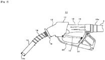
- the fueling nozzle 11 is, as shown in Fig. 2 , constituted by a main body 12, a discharge pipe 13, a grip 15 projecting from the main body 12 for handling a valve opening lever 14 and so on.
- the main body 12 is, as shown in Fig. 3 , formed a fuel oil passage, and the main body 12 includes a main valve 12a that opens to flow fuel oil therein when a valve opening lever 14 (refer to Fig. 2 ) is operated, and an automatic valve closing mechanism 12b that releases the engagement between the main valve 12a and the valve opening lever 14 to terminate fueling when sealed with a liquid surface in a tank to which fuel is supplied.
- the discharge pipe 13 (refer to Fig. 2 ) incorporates a liquid level detecting pipe (not shown) extending from the automatic valve closing mechanism 12b, and the liquid level detecting pipe is arranged so as to open on its discharge end side.
- the discharge pipe 13 is made of aluminum alloy for example, and includes: a reinforcing ring 13a incorporated in a discharge end thereof; an oil guard (oil receiving portion) 18 mounted to an end portion on the main body 12 side; and an anchor spring 19 whose one end is fixed near the oil guard 18 and another end extends on the discharge end side.
- a reinforcing ring 13a incorporated in a discharge end thereof
- an oil guard (oil receiving portion) 18 mounted to an end portion on the main body 12 side
- an anchor spring 19 whose one end is fixed near the oil guard 18 and another end extends on the discharge end side.
- Fig. 3 is omitted illustration of the oil guard 18.
- the reinforcing ring 13a is mounted to avoid a condition that fueling cannot be carried out due to deformation of the discharge end of the discharge pipe 13 when a fueling operator accidentally drops the fueling nozzle 11.
- the oil guard 18 will be described below.
- the anchor spring 19 is mounted to avoid that an end portion of the anchor spring 19 on the reinforcing ring 13a side contacts the in-vehicle tank and the oil guard 18 collides with the in-vehicle tank to break when the discharge pipe 13 is inserted into the in-vehicle tank.
- the oil guard 18 is mounted to prevent that fuel oil adhering to the discharge pipe 13 enters through the discharge pipe 13 in the main body 12 after fueling when the fueling nozzle 11 is inclined to direct the discharge pipe 13 upward.
- the oil guard 18 is, as shown in Figs. 4 and 5 , constituted by a cylindrical portion 18a and an extending portion 18b radially extending from one end of the cylindrical portion 18a, and inside the cylindrical portion 18a, sealing portions 18c and guard portions 18d which cover an outer periphery of the discharge pipe 13 are separately mounted in two stages.
- ribs 18e (18e1-18e3) formed in multi stages and reinforcing members 18f reinforcing the extending portion 18b to prevent it from deforming.
- the sealing portion 18c is, in order to prevent fuel oil from entering therein, attached to the discharge pipe 13 such that no clearance generates between them.
- the guard portion 18d is mounted to prevent the oil guard 18 from inclining and to fix the oil guard 18 to the discharge pipe 13 together with the sealing portion 18c, and has a clearances 18g to incline toward the discharge end of the discharge pipe 13.
- the ribs 18e are formed from inside to outside in three stages, and heights thereof gradually increase from the inside rib 18e1 to the outside rib 18e3. Between these ribs 18e are formed valley portions 18h (18h1-18h3) where fuel oils are stored, and capacities thereof gradually increase from inside to outside.
- the reinforcing members 18f are arranged to divide the ribs 18e into four at 90° intervals.
- the number and arrangement of the reinforcing members 18f are just exemplified, the more the number of the reinforcing members 18f becomes, the less the capacities of the valley portions 18h2, 18h3 become, so that the number of the reinforcing members 18f is preferably suppressed while minimum strength of the oil guard 18 is secured.
- the grip 16 shown in Figs. 2 and 3 is made of metal with conductivity, and a flow passage communicating with a flow passage of the main body 12 is formed therein, and the grip 15 includes a connecting portion 15a to which the fueling hose 2 is connected.
- the grip 15 is covered and protected by a conductive cover 16 made of conductive resin or the like.
- a conducting wire 32 (refer to Fig. 6 ) communicating with a lamp circuit described below, and the grip 15 and the conductive cover 16 have conductivity as described above, so that static electricity charged to an operator who holds the conductive cover 16 of the grip 15 flows through the conducting wire into the lamp circuit.
- the conductive cover 16 is formed along outlines of the main body 12 and the grip 15, and includes a cutout 16a extending in an axial direction of the grip 15. Enlarging the conductive cover 16 through the cutout 16a allows it to easily be attached to or detached from the grip 15.
- portions to which both ends 16b, 16c of the conductive cover 16 are attached are not formed to be cylindrical or columnar, and making outer diameters thereof uneven prevents the conductive cover 16 from rotating around the axis thereof also when the conductive cover 16 is fixed to the main body 12 and the grip 15 through the both ends 16b, 16c.
- manufacture date is described on a surface of the conductive cover 16 as rough indication of time for exchange (for example about three years), and in order to deal with customers who prefer cleanliness, the surface of the conductive cover 16 is preferably be antibacterially formed.
- a cover scarf 17 as shown in Fig. 2 .
- the main body 12 can be protected, and color coding based on kinds of oil allows a worker to confirm which fueling nozzle 11 corresponds to which kind of oil at first sight.
- Fig. 3 is omitted the indication of the cover scarf 17.
- a guard 20 is mounted to protect a valve opening lever 14, and the guard 20 is provided with a latch 21 for allowing an end of the valve opening lever 14 to slide, which enables operation of the valve opening lever 14.
- the lamp circuit which removes static electricity charged to a body of a worker operating the fueling nozzle 11 shown in Fig. 2 and others, and executes control of turning on or off a destaticization confirming lamp 8 shown in Fig. 1 , will be explained with reference to Fig. 6 .
- the lamp circuit 31 connects the grip 15 of the fueling nozzle 11 and the destaticization confirming lamp 8 with a conducting wire 32; between them are disposed a comparator 33 for detecting static electricity of the fueling nozzle 11; between the fueling nozzle 11 and the holding circuit 34 are parallelly connected destaticizing circuits 36 through a conducting wire 35; and to the holding circuit 34 is connected a reset circuit 38 through a conducting wire 37.
- the comparator 33 compares a voltage inputted from the input portion 33a with a reference voltage. When the input voltage is higher than the reference voltage, the comparator 33 outputs HIGH voltage, and when the input voltage is lower than the reference voltage, the comparator 33 outputs LOW voltage.
- outputting HIGH voltage from the output portion 33b indicates that static electricity flows through the fueling nozzle 11, which turns on the destaticization confirming lamp 8.
- the holding circuit 34 is disposed to sustain lighting of the destaticization confirming lamp 8 when HIGH voltage has not outputted from the output portion 33b after HIGH voltage had been outputted from the output portion 33b of the comparator 33. This is because static electricity flows through the comparator 33 for an instant, and it is difficult for a worker to visually recognize lighting even through the destaticization confirming lamp 8 lights for the moment only.
- the destaticizing circuit 36 is a relay circuit, and is mounted to connect contacts to release static electricity flowing through the fueling nozzle 11 to the ground when HIGH voltage is outputted from the output portion 33b of the comparator 33. When LOW voltage is outputted from the output portion 33b of the comparator 33, the destaticizing circuit 36 releases the connection of the contacts.
- the reset circuit 38 is mounted to prevent the destaticization confirming lamp 8 from continuously lighting by releasing sustainment of the holding circuit 34 to turn off the destaticization confirming lamp 8 when a predetermined time has passed after the holding circuit 34 starts sustainment of a circuit.
- condition that fueling becomes possible by the fueling mechanism of the fueling apparatus 1 is set to be a case that both of ON signal of the nozzle switch that is generated when the fueling nozzle 11 is detached from a nozzle hook (not shown) and a signal indicating the contacts are not connected with each other, that is, static electricity does not flow, from the destaticizing circuit 36 are inputted, after the operator detached from the static electricity removal pad 7, fuel oil is not supplied unless the operator is not electrified, so that it is safety.
- the oil guard 18 can be stored fuel oil attached to the discharge pipe 13 in the valley portion18h, which prevents the fuel oil from being guided along the discharge pipe 13 and dropping toward the main body 12. Further, the oil guard 18 has a small diameter, so that a state inside fueling spout of the in-vehicle tank can be recognized during fueling operation, which enables safety fueling operation without leakage of fuel oil from fueling spout.
- This fueling nozzle 41 is provided with a main body 42, a grip 43 and a conductive cover 44 whose shapes are different from those of the main body 12, the grip 15 and the conductive cover 16 of the fueling nozzle 11 shown in Fig. 2 , and other components of the fueling nozzle 41 are the same as those of the fueling nozzle 11.
- the conductive cover 44 of the embodiment is not attached to the main body 42 but is attached to the grip 43 only.
- a cutout 44a extends in an axial direction of the grip 43 to easily perform attachment and detachment to the grip 43.
- a connecting side (right side of the figure) of the grip 43 is not formed to be cylindrical, and outer diameter of the grip 43 is not uniform, so that the conductive cover 44 is fixed to the grip 43 at an end 44a and the rotation of the grip 43 around the axis thereof can be prevented also.
- the cover scarf 17 on the main body 12 side of the conductive cover 16 is attached the cover scarf 17.
- the cover scarf can directly be attached to the main body 42.
Landscapes
- Engineering & Computer Science (AREA)
- Mechanical Engineering (AREA)
- Loading And Unloading Of Fuel Tanks Or Ships (AREA)
- Cooling, Air Intake And Gas Exhaust, And Fuel Tank Arrangements In Propulsion Units (AREA)
Claims (7)
- Eine Zapfpistole (11) bestehend aus:einem Hauptventil konfiguriert für Geöffnung durch die Benutzung eines Ventilöffnungshebels (14) so, dass der Kraftstoff ausfließen kann;einem automatischen Ventilverschlussmechanismus (12b) konfiguriert für Freigebung den Eingriff zwischen dem Hauptventil (12a) und dem Ventilöffnungshebel (14) und Beendung die Betankung, sobald die Oberfläche der Flüssigkeit im Tank, dem Kraftstoff gefüllt wird, festgestellt wird;einem Hauptteil (12) mit dem Hauptventil (12a) und dem automatischen Ventilverschlussmechanismus (12b);einem Griff (15) aus leitendem Metal, der der konfiguriert is für Gehaltung zusammen mit dem Ventilöffnungshebel (14), wenn der Ventilöffnungshebel bedient wird;einem Betankungsschlauch (2), der mit dem Griff (15) verbunden ist, wobei der Betankungsschlauch ist konfiguriert für Zulaufung Kraftstoff zum Hauptteils (12);einem Ablassrohr (13) konfiguriert für Ablassen von Kraftstoff, der durch das Hauptventil geflossen ist (12a);einem Leitungsdraht (32), der an den Betankungsschlauch (2) montiert und mit dem Griff (15) verbunden ist; undeiner leitfähigen Abdeckung (16), die den Griff (15) abdeckt; und einem Kraftstoffschutz (18), der an dem Abschnitt angebracht ist, an dem das Ablassrohr (13) am Hauptteil (12) befestigt ist, wobei der Krafstoffschutz zum Auffangen von aus dem Ablassrohr in Richtung des Hauptteils (12) tropfendem Kraftstoff konfiguriert ist; dadurch gekennzeichnet, dasseine Mehrzahl von Rippen (18e), die Talabschnitte (18h) bilden, die zu der Lagerung von abgetropftem Kraftstoff konfiguriert sind, kontinuierlich an einer Fläche des Kraftstoffschutzes (16) an der Seite des Ablassrohrs (13) angebracht ist, und eine Mehrzahl von Verstärkungselementen (18g), die zum Verbinden der Rippen (18e) konfiguriert sind, an dem Kraftstoffschutz angebracht ist.
- Die Zapfpistole (11) gemäß Anspruch 1, wobei die leitfähige Abdeckung (16) an dem Endstück (16c) des Griffs (15) auf der Seite des Betankungsschlauchs (2) befestigt Ist.
- Die Zapfpistole (11) gemäß Anspruch 1, wobei die leitfähige Abdeckung (16) an dem Endstück (16b) des Griffs (15) auf der Seite des Hauptteils (12) befestigt ist.
- Die Zapfpistole (11) gemäß Anspruch 1, wobei die leitfähige Abdeckung (16) an dem Endstück (16c) des Griffs (15) auf der Seite des Betankungsschlauchs (2) und an dem Endstück (16b) des Griffs auf der Seite des Hauptteils (12) befestigt ist.
- Die Zapfpistole (11) gemäß eines der Ansprüche 2, 3 oder 4, wobei die leitfähige Abdeckung (16) einen Ausschnitt (16a) aufweist, der sich in axialer Richtung des Griffs (15) erstreckt.
- Die Zapfpistole (11) gemäß Anspruch 1, wobei die Rippen (18e) stehen so, dass sie, von der Seite des Auslassrohrs ausgesehen, konzentrischgraphische Umrisse mit dem Ablassrohr (13) bilden und eine äußere Rippe (18e3) erstreckt sich auf der Seite des Auslassrohrs im Vergleich zu einer inneren Rippe (18e1).
- Die Zapfpistole (11) gemäß Anspruch 1 oder 6, wobei der Kraftstoffschutz (18) umfasst:ein Dichtungsabschnitt (18c), der das Abslassrohr (13) umgibt, um den Kraftstoffschutz (18) an das Abslassrohr (13) anzupassen, und das Eindringen den Krafstoffs verhindert; undein Schutzabschnitt (18d), der das Abslassrohr (13) umgibt, um den Kraftstoffschutz (16) an das Ablassrohr anzupassen zusammen mit dem Dichtungsabschnitt (18c), und verhindert, dass sich der Kraftstoffschutz (18) zum Ablassrohr neigt.
Applications Claiming Priority (1)
| Application Number | Priority Date | Filing Date | Title |
|---|---|---|---|
| PCT/JP2017/008062 WO2018158872A1 (ja) | 2017-03-01 | 2017-03-01 | 給油ノズル |
Publications (3)
| Publication Number | Publication Date |
|---|---|
| EP3590884A1 EP3590884A1 (de) | 2020-01-08 |
| EP3590884A4 EP3590884A4 (de) | 2020-10-28 |
| EP3590884B1 true EP3590884B1 (de) | 2023-03-29 |
Family
ID=63370630
Family Applications (1)
| Application Number | Title | Priority Date | Filing Date |
|---|---|---|---|
| EP17898603.0A Active EP3590884B1 (de) | 2017-03-01 | 2017-03-01 | Zapfpistole zur betankung |
Country Status (11)
| Country | Link |
|---|---|
| EP (1) | EP3590884B1 (de) |
| JP (1) | JP6811943B2 (de) |
| KR (1) | KR102276574B1 (de) |
| CN (1) | CN110382402B (de) |
| CR (1) | CR20190398A (de) |
| MY (1) | MY198480A (de) |
| PH (1) | PH12019501978A1 (de) |
| RU (1) | RU2723231C1 (de) |
| SG (1) | SG11201907692PA (de) |
| WO (1) | WO2018158872A1 (de) |
| ZA (1) | ZA201905022B (de) |
Families Citing this family (3)
| Publication number | Priority date | Publication date | Assignee | Title |
|---|---|---|---|---|
| KR102276574B1 (ko) * | 2017-03-01 | 2021-07-15 | 가부시끼가이샤 다쓰노 | 급유노즐 |
| KR102533031B1 (ko) * | 2023-01-06 | 2023-05-17 | 주식회사 덕신코퍼레이션 | 자동 유체펌프용 주유건 |
| WO2026033959A1 (ja) | 2024-08-09 | 2026-02-12 | 株式会社タツノ | 給油ノズル |
Citations (1)
| Publication number | Priority date | Publication date | Assignee | Title |
|---|---|---|---|---|
| EP3590884A1 (de) * | 2017-03-01 | 2020-01-08 | Tatsuno Corporation | Zapfpistole zur betankung |
Family Cites Families (8)
| Publication number | Priority date | Publication date | Assignee | Title |
|---|---|---|---|---|
| JP3956295B2 (ja) | 2002-12-09 | 2007-08-08 | 株式会社タツノ・メカトロニクス | 給油装置 |
| US7255142B2 (en) * | 2003-12-19 | 2007-08-14 | M. Carder Industries, Inc. | Fuel nozzle guard |
| JP4292420B2 (ja) * | 2005-12-08 | 2009-07-08 | 株式会社タツノ・メカトロニクス | 給油ノズル |
| JP4871799B2 (ja) * | 2007-07-06 | 2012-02-08 | トキコテクノ株式会社 | 燃料供給装置 |
| CN201686480U (zh) * | 2010-05-20 | 2010-12-29 | 中国人民解放军总后勤部油料研究所 | 油气回收自封加油枪 |
| JP2012091838A (ja) * | 2010-10-28 | 2012-05-17 | Tatsuno Corp | 給油ノズル |
| CN204778803U (zh) * | 2015-07-09 | 2015-11-18 | 郑州永邦环保科技有限公司 | 一种带有油气回收结构的加油枪 |
| CN205442628U (zh) * | 2016-03-31 | 2016-08-10 | 稳恩佳力佳(北京)石油化工设备有限公司 | 加油枪漏油收集装置、加油机和加油枪 |
-
2017
- 2017-03-01 KR KR1020197024571A patent/KR102276574B1/ko active Active
- 2017-03-01 SG SG11201907692PA patent/SG11201907692PA/en unknown
- 2017-03-01 EP EP17898603.0A patent/EP3590884B1/de active Active
- 2017-03-01 CR CR20190398A patent/CR20190398A/es unknown
- 2017-03-01 MY MYPI2019004530A patent/MY198480A/en unknown
- 2017-03-01 JP JP2019502354A patent/JP6811943B2/ja active Active
- 2017-03-01 CN CN201780087721.2A patent/CN110382402B/zh active Active
- 2017-03-01 RU RU2019130730A patent/RU2723231C1/ru active
- 2017-03-01 WO PCT/JP2017/008062 patent/WO2018158872A1/ja not_active Ceased
-
2019
- 2019-07-30 ZA ZA2019/05022A patent/ZA201905022B/en unknown
- 2019-08-28 PH PH12019501978A patent/PH12019501978A1/en unknown
Patent Citations (1)
| Publication number | Priority date | Publication date | Assignee | Title |
|---|---|---|---|---|
| EP3590884A1 (de) * | 2017-03-01 | 2020-01-08 | Tatsuno Corporation | Zapfpistole zur betankung |
Also Published As
| Publication number | Publication date |
|---|---|
| JPWO2018158872A1 (ja) | 2019-12-26 |
| EP3590884A1 (de) | 2020-01-08 |
| KR20190119049A (ko) | 2019-10-21 |
| JP6811943B2 (ja) | 2021-01-13 |
| SG11201907692PA (en) | 2019-09-27 |
| ZA201905022B (en) | 2020-12-23 |
| PH12019501978A1 (en) | 2020-06-15 |
| CN110382402B (zh) | 2021-07-30 |
| EP3590884A4 (de) | 2020-10-28 |
| MY198480A (en) | 2023-08-31 |
| CN110382402A (zh) | 2019-10-25 |
| NZ755692A (en) | 2023-09-29 |
| RU2723231C1 (ru) | 2020-06-09 |
| CR20190398A (es) | 2019-11-26 |
| KR102276574B1 (ko) | 2021-07-15 |
| WO2018158872A1 (ja) | 2018-09-07 |
Similar Documents
| Publication | Publication Date | Title |
|---|---|---|
| EP3590884B1 (de) | Zapfpistole zur betankung | |
| US8800611B2 (en) | Insert element for a container suitable for filling with urea at a filling station | |
| EP0026727A2 (de) | Apparat zur Rückgewinnung von Kraftstoffdämpfen | |
| GB2575145A (en) | System and method for distributing and dispensing liquids | |
| US10081241B2 (en) | Diesel fuel guard | |
| US9783047B2 (en) | Device for protection against incorrect refuelling | |
| ITTV20080119A1 (it) | Dispositivo antifurto, particolarmente per impedire la estrazione di carburante da serbatoi | |
| US6966349B1 (en) | Misfueling prevention device | |
| NZ755692B2 (en) | Refueling nozzle | |
| WO2007104762A1 (en) | Fuel-dispensing nozzle inhibitor | |
| US20140034176A1 (en) | Anti-Siphon Assembly | |
| JP6283912B2 (ja) | 燃料給油装置のアース構造 | |
| JP2012091542A (ja) | セルフスタンド対応型安全装置を備えた自動車 | |
| JP4858534B2 (ja) | 給油ノズル | |
| EP3164287B1 (de) | Absaugschutzvorrichtung, insbesondere zur vermeidung der extraktion von kraftstoff aus tanks | |
| JP2007153429A (ja) | 給油ノズル | |
| EP2243995B1 (de) | Vorrichtung zur Erkennung von Undichtigkeiten in einem LPG Verteilungsnetz | |
| JP2003128199A (ja) | 給油装置 | |
| EP0566026B1 (de) | Sicherheitsvorrichtung eines Einfüllstutzens für Fahrzeugkraftstoffbehälter | |
| WO2016001346A1 (en) | Removal prevention device for anti-siphoning devices for tanks | |
| CN215924375U (zh) | 油泵供电电路和航油加油装置 | |
| EP1459925A2 (de) | Sicherheitskupplung für Dieseltankeinfüllstutzen | |
| JP3373729B2 (ja) | 給油設備における混油防止機構 | |
| KR19990017594A (ko) | 연료캡 고정장치 | |
| KR100610752B1 (ko) | 주유시 연료가 조기 차단되는 것을 방지하는 연료 분리장치 |
Legal Events
| Date | Code | Title | Description |
|---|---|---|---|
| STAA | Information on the status of an ep patent application or granted ep patent |
Free format text: STATUS: THE INTERNATIONAL PUBLICATION HAS BEEN MADE |
|
| PUAI | Public reference made under article 153(3) epc to a published international application that has entered the european phase |
Free format text: ORIGINAL CODE: 0009012 |
|
| STAA | Information on the status of an ep patent application or granted ep patent |
Free format text: STATUS: REQUEST FOR EXAMINATION WAS MADE |
|
| 17P | Request for examination filed |
Effective date: 20190822 |
|
| AK | Designated contracting states |
Kind code of ref document: A1 Designated state(s): AL AT BE BG CH CY CZ DE DK EE ES FI FR GB GR HR HU IE IS IT LI LT LU LV MC MK MT NL NO PL PT RO RS SE SI SK SM TR |
|
| AX | Request for extension of the european patent |
Extension state: BA ME |
|
| DAV | Request for validation of the european patent (deleted) | ||
| DAX | Request for extension of the european patent (deleted) | ||
| A4 | Supplementary search report drawn up and despatched |
Effective date: 20200930 |
|
| RIC1 | Information provided on ipc code assigned before grant |
Ipc: B67D 7/32 20100101ALI20200924BHEP Ipc: B67D 7/46 20100101ALN20200924BHEP Ipc: B67D 7/04 20100101ALI20200924BHEP Ipc: B67D 7/42 20100101AFI20200924BHEP |
|
| GRAP | Despatch of communication of intention to grant a patent |
Free format text: ORIGINAL CODE: EPIDOSNIGR1 |
|
| STAA | Information on the status of an ep patent application or granted ep patent |
Free format text: STATUS: GRANT OF PATENT IS INTENDED |
|
| RIC1 | Information provided on ipc code assigned before grant |
Ipc: B67D 7/46 20100101ALN20221115BHEP Ipc: B67D 7/04 20100101ALI20221115BHEP Ipc: B67D 7/32 20100101ALI20221115BHEP Ipc: B67D 7/42 20100101AFI20221115BHEP |
|
| RIC1 | Information provided on ipc code assigned before grant |
Ipc: B67D 7/46 20100101ALN20221122BHEP Ipc: B67D 7/04 20100101ALI20221122BHEP Ipc: B67D 7/32 20100101ALI20221122BHEP Ipc: B67D 7/42 20100101AFI20221122BHEP |
|
| RIC1 | Information provided on ipc code assigned before grant |
Ipc: B67D 7/46 20100101ALN20221128BHEP Ipc: B67D 7/04 20100101ALI20221128BHEP Ipc: B67D 7/32 20100101ALI20221128BHEP Ipc: B67D 7/42 20100101AFI20221128BHEP |
|
| INTG | Intention to grant announced |
Effective date: 20221214 |
|
| GRAS | Grant fee paid |
Free format text: ORIGINAL CODE: EPIDOSNIGR3 |
|
| GRAA | (expected) grant |
Free format text: ORIGINAL CODE: 0009210 |
|
| STAA | Information on the status of an ep patent application or granted ep patent |
Free format text: STATUS: THE PATENT HAS BEEN GRANTED |
|
| AK | Designated contracting states |
Kind code of ref document: B1 Designated state(s): AL AT BE BG CH CY CZ DE DK EE ES FI FR GB GR HR HU IE IS IT LI LT LU LV MC MK MT NL NO PL PT RO RS SE SI SK SM TR |
|
| REG | Reference to a national code |
Ref country code: CH Ref legal event code: EP |
|
| REG | Reference to a national code |
Ref country code: DE Ref legal event code: R096 Ref document number: 602017067327 Country of ref document: DE |
|
| REG | Reference to a national code |
Ref country code: AT Ref legal event code: REF Ref document number: 1556563 Country of ref document: AT Kind code of ref document: T Effective date: 20230415 |
|
| REG | Reference to a national code |
Ref country code: NL Ref legal event code: FP Ref country code: IE Ref legal event code: FG4D |
|
| REG | Reference to a national code |
Ref country code: SK Ref legal event code: T3 Ref document number: E 41488 Country of ref document: SK |
|
| REG | Reference to a national code |
Ref country code: LT Ref legal event code: MG9D |
|
| PG25 | Lapsed in a contracting state [announced via postgrant information from national office to epo] |
Ref country code: RS Free format text: LAPSE BECAUSE OF FAILURE TO SUBMIT A TRANSLATION OF THE DESCRIPTION OR TO PAY THE FEE WITHIN THE PRESCRIBED TIME-LIMIT Effective date: 20230329 Ref country code: NO Free format text: LAPSE BECAUSE OF FAILURE TO SUBMIT A TRANSLATION OF THE DESCRIPTION OR TO PAY THE FEE WITHIN THE PRESCRIBED TIME-LIMIT Effective date: 20230629 Ref country code: LV Free format text: LAPSE BECAUSE OF FAILURE TO SUBMIT A TRANSLATION OF THE DESCRIPTION OR TO PAY THE FEE WITHIN THE PRESCRIBED TIME-LIMIT Effective date: 20230329 Ref country code: LT Free format text: LAPSE BECAUSE OF FAILURE TO SUBMIT A TRANSLATION OF THE DESCRIPTION OR TO PAY THE FEE WITHIN THE PRESCRIBED TIME-LIMIT Effective date: 20230329 Ref country code: HR Free format text: LAPSE BECAUSE OF FAILURE TO SUBMIT A TRANSLATION OF THE DESCRIPTION OR TO PAY THE FEE WITHIN THE PRESCRIBED TIME-LIMIT Effective date: 20230329 |
|
| REG | Reference to a national code |
Ref country code: AT Ref legal event code: MK05 Ref document number: 1556563 Country of ref document: AT Kind code of ref document: T Effective date: 20230329 |
|
| PG25 | Lapsed in a contracting state [announced via postgrant information from national office to epo] |
Ref country code: SE Free format text: LAPSE BECAUSE OF FAILURE TO SUBMIT A TRANSLATION OF THE DESCRIPTION OR TO PAY THE FEE WITHIN THE PRESCRIBED TIME-LIMIT Effective date: 20230329 Ref country code: GR Free format text: LAPSE BECAUSE OF FAILURE TO SUBMIT A TRANSLATION OF THE DESCRIPTION OR TO PAY THE FEE WITHIN THE PRESCRIBED TIME-LIMIT Effective date: 20230630 Ref country code: FI Free format text: LAPSE BECAUSE OF FAILURE TO SUBMIT A TRANSLATION OF THE DESCRIPTION OR TO PAY THE FEE WITHIN THE PRESCRIBED TIME-LIMIT Effective date: 20230329 |
|
| PG25 | Lapsed in a contracting state [announced via postgrant information from national office to epo] |
Ref country code: SM Free format text: LAPSE BECAUSE OF FAILURE TO SUBMIT A TRANSLATION OF THE DESCRIPTION OR TO PAY THE FEE WITHIN THE PRESCRIBED TIME-LIMIT Effective date: 20230329 Ref country code: RO Free format text: LAPSE BECAUSE OF FAILURE TO SUBMIT A TRANSLATION OF THE DESCRIPTION OR TO PAY THE FEE WITHIN THE PRESCRIBED TIME-LIMIT Effective date: 20230329 Ref country code: PT Free format text: LAPSE BECAUSE OF FAILURE TO SUBMIT A TRANSLATION OF THE DESCRIPTION OR TO PAY THE FEE WITHIN THE PRESCRIBED TIME-LIMIT Effective date: 20230731 Ref country code: ES Free format text: LAPSE BECAUSE OF FAILURE TO SUBMIT A TRANSLATION OF THE DESCRIPTION OR TO PAY THE FEE WITHIN THE PRESCRIBED TIME-LIMIT Effective date: 20230329 Ref country code: EE Free format text: LAPSE BECAUSE OF FAILURE TO SUBMIT A TRANSLATION OF THE DESCRIPTION OR TO PAY THE FEE WITHIN THE PRESCRIBED TIME-LIMIT Effective date: 20230329 Ref country code: AT Free format text: LAPSE BECAUSE OF FAILURE TO SUBMIT A TRANSLATION OF THE DESCRIPTION OR TO PAY THE FEE WITHIN THE PRESCRIBED TIME-LIMIT Effective date: 20230329 |
|
| PG25 | Lapsed in a contracting state [announced via postgrant information from national office to epo] |
Ref country code: PL Free format text: LAPSE BECAUSE OF FAILURE TO SUBMIT A TRANSLATION OF THE DESCRIPTION OR TO PAY THE FEE WITHIN THE PRESCRIBED TIME-LIMIT Effective date: 20230329 Ref country code: IS Free format text: LAPSE BECAUSE OF FAILURE TO SUBMIT A TRANSLATION OF THE DESCRIPTION OR TO PAY THE FEE WITHIN THE PRESCRIBED TIME-LIMIT Effective date: 20230729 |
|
| REG | Reference to a national code |
Ref country code: DE Ref legal event code: R097 Ref document number: 602017067327 Country of ref document: DE |
|
| PGFP | Annual fee paid to national office [announced via postgrant information from national office to epo] |
Ref country code: SK Payment date: 20231208 Year of fee payment: 8 |
|
| PG25 | Lapsed in a contracting state [announced via postgrant information from national office to epo] |
Ref country code: DK Free format text: LAPSE BECAUSE OF FAILURE TO SUBMIT A TRANSLATION OF THE DESCRIPTION OR TO PAY THE FEE WITHIN THE PRESCRIBED TIME-LIMIT Effective date: 20230329 |
|
| PGFP | Annual fee paid to national office [announced via postgrant information from national office to epo] |
Ref country code: NL Payment date: 20231219 Year of fee payment: 8 Ref country code: CZ Payment date: 20231208 Year of fee payment: 8 |
|
| PLBE | No opposition filed within time limit |
Free format text: ORIGINAL CODE: 0009261 |
|
| STAA | Information on the status of an ep patent application or granted ep patent |
Free format text: STATUS: NO OPPOSITION FILED WITHIN TIME LIMIT |
|
| 26N | No opposition filed |
Effective date: 20240103 |
|
| PG25 | Lapsed in a contracting state [announced via postgrant information from national office to epo] |
Ref country code: SI Free format text: LAPSE BECAUSE OF FAILURE TO SUBMIT A TRANSLATION OF THE DESCRIPTION OR TO PAY THE FEE WITHIN THE PRESCRIBED TIME-LIMIT Effective date: 20230329 |
|
| PG25 | Lapsed in a contracting state [announced via postgrant information from national office to epo] |
Ref country code: SI Free format text: LAPSE BECAUSE OF FAILURE TO SUBMIT A TRANSLATION OF THE DESCRIPTION OR TO PAY THE FEE WITHIN THE PRESCRIBED TIME-LIMIT Effective date: 20230329 |
|
| PGFP | Annual fee paid to national office [announced via postgrant information from national office to epo] |
Ref country code: IT Payment date: 20231220 Year of fee payment: 8 |
|
| REG | Reference to a national code |
Ref country code: DE Ref legal event code: R119 Ref document number: 602017067327 Country of ref document: DE |
|
| REG | Reference to a national code |
Ref country code: CH Ref legal event code: PL |
|
| PG25 | Lapsed in a contracting state [announced via postgrant information from national office to epo] |
Ref country code: BG Free format text: LAPSE BECAUSE OF FAILURE TO SUBMIT A TRANSLATION OF THE DESCRIPTION OR TO PAY THE FEE WITHIN THE PRESCRIBED TIME-LIMIT Effective date: 20230329 |
|
| PG25 | Lapsed in a contracting state [announced via postgrant information from national office to epo] |
Ref country code: LU Free format text: LAPSE BECAUSE OF NON-PAYMENT OF DUE FEES Effective date: 20240301 |
|
| PG25 | Lapsed in a contracting state [announced via postgrant information from national office to epo] |
Ref country code: MC Free format text: LAPSE BECAUSE OF FAILURE TO SUBMIT A TRANSLATION OF THE DESCRIPTION OR TO PAY THE FEE WITHIN THE PRESCRIBED TIME-LIMIT Effective date: 20230329 |
|
| GBPC | Gb: european patent ceased through non-payment of renewal fee |
Effective date: 20240301 |
|
| PG25 | Lapsed in a contracting state [announced via postgrant information from national office to epo] |
Ref country code: MC Free format text: LAPSE BECAUSE OF FAILURE TO SUBMIT A TRANSLATION OF THE DESCRIPTION OR TO PAY THE FEE WITHIN THE PRESCRIBED TIME-LIMIT Effective date: 20230329 Ref country code: LU Free format text: LAPSE BECAUSE OF NON-PAYMENT OF DUE FEES Effective date: 20240301 Ref country code: BG Free format text: LAPSE BECAUSE OF FAILURE TO SUBMIT A TRANSLATION OF THE DESCRIPTION OR TO PAY THE FEE WITHIN THE PRESCRIBED TIME-LIMIT Effective date: 20230329 |
|
| REG | Reference to a national code |
Ref country code: BE Ref legal event code: MM Effective date: 20240331 |
|
| PG25 | Lapsed in a contracting state [announced via postgrant information from national office to epo] |
Ref country code: DE Free format text: LAPSE BECAUSE OF NON-PAYMENT OF DUE FEES Effective date: 20241001 |
|
| PG25 | Lapsed in a contracting state [announced via postgrant information from national office to epo] |
Ref country code: BE Free format text: LAPSE BECAUSE OF NON-PAYMENT OF DUE FEES Effective date: 20240331 |
|
| PG25 | Lapsed in a contracting state [announced via postgrant information from national office to epo] |
Ref country code: GB Free format text: LAPSE BECAUSE OF NON-PAYMENT OF DUE FEES Effective date: 20240301 |
|
| PG25 | Lapsed in a contracting state [announced via postgrant information from national office to epo] |
Ref country code: FR Free format text: LAPSE BECAUSE OF NON-PAYMENT OF DUE FEES Effective date: 20240331 |
|
| PG25 | Lapsed in a contracting state [announced via postgrant information from national office to epo] |
Ref country code: IE Free format text: LAPSE BECAUSE OF NON-PAYMENT OF DUE FEES Effective date: 20240301 |
|
| PG25 | Lapsed in a contracting state [announced via postgrant information from national office to epo] |
Ref country code: IE Free format text: LAPSE BECAUSE OF NON-PAYMENT OF DUE FEES Effective date: 20240301 Ref country code: GB Free format text: LAPSE BECAUSE OF NON-PAYMENT OF DUE FEES Effective date: 20240301 Ref country code: FR Free format text: LAPSE BECAUSE OF NON-PAYMENT OF DUE FEES Effective date: 20240331 Ref country code: DE Free format text: LAPSE BECAUSE OF NON-PAYMENT OF DUE FEES Effective date: 20241001 Ref country code: BE Free format text: LAPSE BECAUSE OF NON-PAYMENT OF DUE FEES Effective date: 20240331 Ref country code: CH Free format text: LAPSE BECAUSE OF NON-PAYMENT OF DUE FEES Effective date: 20240331 |
|
| PG25 | Lapsed in a contracting state [announced via postgrant information from national office to epo] |
Ref country code: CY Free format text: LAPSE BECAUSE OF FAILURE TO SUBMIT A TRANSLATION OF THE DESCRIPTION OR TO PAY THE FEE WITHIN THE PRESCRIBED TIME-LIMIT; INVALID AB INITIO Effective date: 20170301 |
|
| PG25 | Lapsed in a contracting state [announced via postgrant information from national office to epo] |
Ref country code: HU Free format text: LAPSE BECAUSE OF FAILURE TO SUBMIT A TRANSLATION OF THE DESCRIPTION OR TO PAY THE FEE WITHIN THE PRESCRIBED TIME-LIMIT; INVALID AB INITIO Effective date: 20170301 |
|
| REG | Reference to a national code |
Ref country code: SK Ref legal event code: MM4A Ref document number: E 41488 Country of ref document: SK Effective date: 20250301 |
|
| PG25 | Lapsed in a contracting state [announced via postgrant information from national office to epo] |
Ref country code: CZ Free format text: LAPSE BECAUSE OF NON-PAYMENT OF DUE FEES Effective date: 20250301 |
|
| PG25 | Lapsed in a contracting state [announced via postgrant information from national office to epo] |
Ref country code: SK Free format text: LAPSE BECAUSE OF NON-PAYMENT OF DUE FEES Effective date: 20250301 |
|
| REG | Reference to a national code |
Ref country code: NL Ref legal event code: MM Effective date: 20250401 |
|
| PG25 | Lapsed in a contracting state [announced via postgrant information from national office to epo] |
Ref country code: TR Free format text: LAPSE BECAUSE OF FAILURE TO SUBMIT A TRANSLATION OF THE DESCRIPTION OR TO PAY THE FEE WITHIN THE PRESCRIBED TIME-LIMIT Effective date: 20230329 |
|
| PG25 | Lapsed in a contracting state [announced via postgrant information from national office to epo] |
Ref country code: NL Free format text: LAPSE BECAUSE OF NON-PAYMENT OF DUE FEES Effective date: 20250401 |
|
| PG25 | Lapsed in a contracting state [announced via postgrant information from national office to epo] |
Ref country code: IT Free format text: LAPSE BECAUSE OF NON-PAYMENT OF DUE FEES Effective date: 20250301 |