EP3591147A1 - Serrure de deux roues ayant une fonction d'alarme - Google Patents
Serrure de deux roues ayant une fonction d'alarme Download PDFInfo
- Publication number
- EP3591147A1 EP3591147A1 EP19184447.1A EP19184447A EP3591147A1 EP 3591147 A1 EP3591147 A1 EP 3591147A1 EP 19184447 A EP19184447 A EP 19184447A EP 3591147 A1 EP3591147 A1 EP 3591147A1
- Authority
- EP
- European Patent Office
- Prior art keywords
- locking
- lock
- locking mechanism
- bracket
- alarm
- Prior art date
- Legal status (The legal status is an assumption and is not a legal conclusion. Google has not performed a legal analysis and makes no representation as to the accuracy of the status listed.)
- Granted
Links
Images


Classifications
-
- E—FIXED CONSTRUCTIONS
- E05—LOCKS; KEYS; WINDOW OR DOOR FITTINGS; SAFES
- E05B—LOCKS; ACCESSORIES THEREFOR; HANDCUFFS
- E05B45/00—Alarm locks
- E05B45/005—Chain-locks, cable-locks or padlocks with alarms
-
- E—FIXED CONSTRUCTIONS
- E05—LOCKS; KEYS; WINDOW OR DOOR FITTINGS; SAFES
- E05B—LOCKS; ACCESSORIES THEREFOR; HANDCUFFS
- E05B67/00—Padlocks; Details thereof
- E05B67/06—Shackles; Arrangement of the shackle
- E05B67/22—Padlocks with sliding shackles, with or without rotary or pivotal movement
- E05B67/24—Padlocks with sliding shackles, with or without rotary or pivotal movement with built- in cylinder locks
-
- E—FIXED CONSTRUCTIONS
- E05—LOCKS; KEYS; WINDOW OR DOOR FITTINGS; SAFES
- E05B—LOCKS; ACCESSORIES THEREFOR; HANDCUFFS
- E05B45/00—Alarm locks
- E05B45/06—Electric alarm locks
-
- E—FIXED CONSTRUCTIONS
- E05—LOCKS; KEYS; WINDOW OR DOOR FITTINGS; SAFES
- E05B—LOCKS; ACCESSORIES THEREFOR; HANDCUFFS
- E05B47/00—Operating or controlling locks or other fastening devices by electric or magnetic means
- E05B47/0001—Operating or controlling locks or other fastening devices by electric or magnetic means with electric actuators; Constructional features thereof
- E05B47/0012—Operating or controlling locks or other fastening devices by electric or magnetic means with electric actuators; Constructional features thereof with rotary electromotors
-
- E—FIXED CONSTRUCTIONS
- E05—LOCKS; KEYS; WINDOW OR DOOR FITTINGS; SAFES
- E05B—LOCKS; ACCESSORIES THEREFOR; HANDCUFFS
- E05B67/00—Padlocks; Details thereof
- E05B67/06—Shackles; Arrangement of the shackle
- E05B67/063—Padlocks with removable shackles
-
- E—FIXED CONSTRUCTIONS
- E05—LOCKS; KEYS; WINDOW OR DOOR FITTINGS; SAFES
- E05B—LOCKS; ACCESSORIES THEREFOR; HANDCUFFS
- E05B71/00—Locks specially adapted for bicycles, other than padlocks
-
- E—FIXED CONSTRUCTIONS
- E05—LOCKS; KEYS; WINDOW OR DOOR FITTINGS; SAFES
- E05B—LOCKS; ACCESSORIES THEREFOR; HANDCUFFS
- E05B45/00—Alarm locks
- E05B45/06—Electric alarm locks
- E05B2045/065—Switch or sensor type used in alarm locks
- E05B2045/0665—Magnetic switches, e.g. reed- or hall-switch
-
- E—FIXED CONSTRUCTIONS
- E05—LOCKS; KEYS; WINDOW OR DOOR FITTINGS; SAFES
- E05B—LOCKS; ACCESSORIES THEREFOR; HANDCUFFS
- E05B47/00—Operating or controlling locks or other fastening devices by electric or magnetic means
- E05B47/0001—Operating or controlling locks or other fastening devices by electric or magnetic means with electric actuators; Constructional features thereof
Definitions
- the present invention relates to a lock with an alarm function for a two-wheeler, with a lock body and a securing bracket which can be moved relative to the lock body between a securing position for securing the two-wheeler and an open position for releasing the two-wheeler, the lock body having a locking mechanism to prevent the Locking the safety bracket in the locking position optionally on the lock body, the lock body further comprising an alarm device for outputting an alarm signal.
- Such a lock can be designed, for example, as a U-bracket lock, which has a rigid, essentially U-shaped securing bracket, or as an articulated lock with an articulated rod as a securing bracket, which has a plurality of pivoting rods which are pivotally connected to one another.
- a two-wheel lock of the type mentioned can also be designed as a so-called frame lock, in which a rotating bracket or swivel bracket engages between the spokes of one of the wheels of a bicycle.
- such a lock can be designed, for example, as a brake disc lock, in which the securing bracket engages in a ventilation opening of a brake disc of a motorcycle or a motor scooter.
- the securing bracket can also be flexible, for example in the form of a chain or a wire rope, which can optionally be locked on the lock body.
- a lock of the type mentioned is used, for example, to secure a two-wheeler to a bicycle stand, a lamppost or another stationary object, or to secure a two-wheeler against unauthorized driving away.
- the securing bracket When the securing bracket is unlocked, the securing bracket can be brought into an open position in which the securing bracket is released from the lock body at one end or completely. Starting from the open position, the securing bracket can be guided, for example, around a frame section of the two-wheeler and a bicycle stand, lamppost or the like, or the securing bracket is only guided through a movable part (e.g. rim, brake disc) of the two-wheeler. The safety bracket can then be (completely) closed and locked on the lock body, in order to secure the two-wheeler against unauthorized removal or unauthorized driving away.
- the safety bracket can be unlocked by the authorized user actuating the locking mechanism of the lock by means of an assigned key or other identification means (e.g. transponder).
- An alarm device that is sensitive to vibrations, for example, must not trigger the output of an alarm signal during the transport of the lock, and activation of the alarm device is not desirable each time the bicycle is locked (e.g. securing the bicycle to a bicycle rack of a motor vehicle).
- a two-wheel lock with an alarm function with the features of claim 1, and in particular in that the locking mechanism can be brought optionally into an unlocking position, a locking position or an alarm activation position, the locking bracket being released for movement into the open position in the unlocking position , wherein in the locking position the locking bracket located in the locking position is locked to the lock body, and wherein the alarm device can be activated or activated by moving the locking mechanism into the alarm activation position.
- the locking mechanism can also - at least temporarily - be brought into an alarm activation position.
- the alarm device of the two-wheel lock can be activated as long as the locking mechanism is in the alarm activation position. Provision can also be made for the alarm device to be activated by temporarily moving the locking mechanism into the alarm activation position, the alarm device being able to remain activated even if the locking mechanism is immediately moved to another position.
- the alarm activation position can form a further (i.e. second) locking position with regard to the locking mechanism, as will be explained below.
- actuation of the locking mechanism of the two-wheel lock by the authorized user is provided in any case, in particular for unlocking or locking, for example by means of an assigned key, by means of an electronic identification means, by transmission a code or a combination thereof.
- actuation of the locking mechanism namely by placing the locking mechanism in an alarm activation position
- the authorized user can not only select the locking state or unlocking state of the locking mechanism, but also determine whether or not the alarm device should be activated or activated.
- the alarm activation position can be determined indirectly (for example from a control signal for the locking mechanism) or directly (for example by a position detector). This results in a comfortable and, in particular, also fail-safe operation of the two-wheel lock and in particular the alarm device.
- the two-wheel lock can be configured such that the alarm device is automatically activated by moving the locking mechanism into the alarm activation position.
- the locking mechanism is designed to be purely mechanical.
- the locking mechanism can have a locking cylinder which can be rotated by means of a key.
- the locking cylinder can be directly or indirectly coupled to one or more bolts to release the locking bracket in the unlocked position and to lock the locking bracket (if it is in the locking position) to the lock body in the locking position.
- the alarm device by turning the lock cylinder by means of the key, the alarm device can be activated directly or indirectly by turning the lock cylinder into a Alarm activation position is brought, which differs from the unlocking position and the locking position or a first locking position.
- the locking cylinder can have a cylinder housing and a cylinder core rotatably mounted in the cylinder housing, the locking position of the locking mechanism corresponding to a first rotational position of the cylinder core, the alarm activation position of the locking mechanism corresponding to a second rotational position of the cylinder core, and the unlocking position of the locking mechanism of a third rotational position corresponds to the cylinder core.
- the user can easily differentiate the different positions or states of the locking mechanism from one another and select them without incorrect operation.
- the locking cylinder can be actuated from the unlocking position in a first direction of rotation or in a second direction of rotation opposite thereto.
- the unlocking position thus forms a central position for the actuation of the locking cylinder in order to bring the locking mechanism or the locking cylinder optionally into another position.
- the locking cylinder can be actuated from the locking position in a first direction of rotation or in a second direction of rotation opposite thereto. The locking position thus forms a central position for the actuation of the locking cylinder.
- the first rotational position, the second rotational position and the third rotational position of the cylinder core can each be offset by 90 ° to one another. This provides the user with a clear, clearly visible distinction between the different rotational positions in order to be able to operate the locking mechanism without errors.
- the first rotational position of the cylinder core with respect to the third rotational position of the cylinder core by an angle of 90 ° the second rotational position of the cylinder core with respect to the third rotational position of the cylinder core by an angle of 90 ° and with respect to the first rotational position of the cylinder core by an angle of 180 ° ,
- the key can be inserted into the cylinder core in two different positions of the cylinder core and can be removed from the cylinder core.
- two different positions of the locking mechanism can be selected, in which the assigned key can be removed from the locking cylinder.
- These two different positions can in particular be two locking positions in order to lock the safety bracket on the lock body (when the alarm device is activated or the alarm device is deactivated).
- the assigned key can be inserted into the cylinder core and removed from the cylinder core both in the first rotational position of the cylinder core and in the second rotational position of the cylinder core.
- the lock cylinder can have a plurality of tumblers which are displaced by inserting the key into the cylinder core.
- a specific locking secret of the respective locking cylinder can be encoded by the multiple tumblers.
- the locking cylinder can be designed as a plate cylinder with a plurality of plate tumblers, as is generally the case, for example DE 102014108355 A1 is known.
- a plate cylinder enables a configuration in which the assigned key can be removed from the cylinder core in two different rotational positions, in particular offset by 180 ° to one another.
- the locking mechanism can have one or more bolts which lock the locking bracket, if this is in the securing position, on the lock body.
- the locking mechanism can have at least one bolt which can be driven by means of the associated key (in particular via a locking cylinder) and which engages with the securing bracket in the locking position of the locking mechanism in order to lock the securing bracket on the lock body.
- the bolt or another bolt that is drivable by means of the locking cylinder can engage the securing bracket in the alarm activation position of the locking mechanism.
- the alarm activation position can form a further locking position of the locking mechanism.
- the securing bracket may have at least one locking recess, with a latch engaging the locking recess when the locking mechanism is in the locking position (or another locking position). In the unlocked position of the locking mechanism, however, the respective latch does not engage in the associated locking recess (s) in the securing bracket.
- the respective locking recess can be designed, for example, as a groove or as a bore.
- the locking cylinder can be coupled to the at least one bolt via a deflection device which deflects a rotary movement of the locking cylinder into a linear movement of the bolt.
- the deflection devices can have at least one eccentric extension (eg pin), another type of cam, or a ramp, an associated one Counter element can be provided (eg guideway, backdrop or counter ramp).
- One element of the deflection device can be assigned to the locking cylinder and another element of the deflection device can be assigned to the respective bolt.
- the linear movement of the bolt can be a lateral, in particular radial, movement with respect to the axis of rotation of the locking cylinder, or an axial movement, in particular offset coaxially or parallel to the axis of rotation of the locking cylinder.
- a rotary movement or pivoting movement of the respective bolt can also be provided, the locking cylinder being able to be coupled to the at least one bolt directly or indirectly, in particular via a deflection device.
- the locking mechanism can be designed electromechanically in some embodiments.
- the locking mechanism can have an electric motor that serves as a servomotor, in particular to drive at least one bolt of the locking mechanism.
- an electric motor can be directly or indirectly coupled to one or more bolts to release the locking bracket in the unlocking position and to lock the locking bracket (if it is in the locking position) to the lock body in the locking position.
- the alarm device can be activated directly or indirectly by bringing the electric motor or a downstream drive element into an alarm activation position that differs from the unlocked position and the locked position or a first locked position.
- the locking mechanism can therefore have at least one bolt which can be driven electrically for a locking movement and / or an unlocking movement and which, in the locking position of the locking mechanism, engages with the securing bracket in order to lock the securing bracket on the lock body.
- the authorized user can actuate an electromechanical locking mechanism, for example, by means of an electronic identification means (e.g. transponder), by transmitting a code (e.g. by radio, in particular via a mobile terminal), by actuating a switch provided on the two-wheel lock or by a combination thereof ,
- an electronic identification means e.g. transponder
- a code e.g. by radio, in particular via a mobile terminal
- an electromechanical locking mechanism can have, for example, an electromagnetic drive device.
- the alarm activation position of the locking mechanism can form a further locking position, ie both in the locking position and in the alarm activation position, the securing bracket, insofar as it is in the securing position, can be locked on the lock body.
- the alarm device can be deactivated in one locking position, the alarm device being activated in the other locking position.
- the user in addition to the unlocking position, in which the alarm device can be deactivated, the user can select one of two different locking positions in which the safety bracket is equally mechanically locked (in particular purely mechanical or electromechanical), but the alarm device is either activated or deactivated.
- Such an embodiment is particularly suitable for a two-wheel lock with a so-called forced locking, in which the locking mechanism must be brought into a locking position in order to be able to remove an assigned key.
- the locking mechanism By actuating the locking mechanism by means of the assigned key for the purpose of locking the securing bracket, the user can thus not only bring about a desired mechanical locking, but can also select in a simple manner whether the alarm device should be activated or not.
- the securing bracket may have at least a first locking recess and at least a second locking recess, the securing bracket being locked to the first locking recess in the locking position of the locking mechanism, and the locking bracket being locked to the second locking recess in the further locking position of the locking mechanism.
- the locking mechanism can have two bolts, wherein in the locking position of the locking mechanism one of the two bolts engages in the first locking recess of the securing bracket, and in the further locking position of the locking mechanism the other of the two locking bolts engages in the second locking recess of the securing bracket.
- the securing bracket has a first bracket end and a second bracket end, each of which has a first locking recess and a second locking recess, wherein in the locking position of the locking mechanism, the one of the two bolts in the first locking recess of the first bracket end engages and the other of the two latches engages in the first locking recess of the second bracket end, and wherein in the further locking position of the locking mechanism one of the two latches engages in the second locking recess of the second bracket end and the other of the two latches in the second locking recess of the first bracket end intervenes.
- the locking mechanism can have only a single latch, which, starting from the unlocked position of the locking mechanism, is moved in the same direction regardless of the direction of a locking actuation of the locking mechanism (in particular regardless of the direction of a rotary actuation of a lock cylinder or electric motor).
- an actuation can take place in two different directions in order to move the locking mechanism into a respective locking position, for example a rotary actuation in two different directions of rotation by means of the assigned key.
- the two different actuation directions can effect the same locking movement direction of the bolt.
- the locking mechanism has a deflection device (in particular the already mentioned deflection device) with mutually symmetrical drive sections which drive the bolt in the same direction regardless of an actuation direction of the locking mechanism.
- a deflection device can have two ramps which are symmetrical to one another and through which the bolt is driven.
- two different actuation directions of the locking mechanism can be distinguished from one another with regard to controlling the alarm device, for example by only addressing a corresponding position detector (for example sensor or switch) in one of two possible actuation directions (for example via a permanent magnet or an elevation).
- the alarm device can be activated and deactivated alternately by repeatedly moving the locking mechanism into the alarm activation position.
- a desired state of the alarm device can be selected by temporarily moving the locking mechanism into the alarm activation position without the locking mechanism having to remain in the alarm activation position.
- a switch between an activated state of the alarm device and a deactivated state of the alarm device can be effected by a respective movement of the locking mechanism into the alarm activation position. This makes it possible, for example, for two positions of the locking mechanism (locking position and unlocking position) to be provided exclusively for the mechanical locking function and that a further position (alarm activation position) is provided exclusively for activating the alarm device.
- Such an embodiment is particularly suitable for a two-wheel lock with a so-called automatic function, in which - unlike the above-mentioned locking requirement - the locking bracket is automatically locked to the lock body by moving the locking bracket from the open position to the locking position, the locking mechanism brought briefly from the locking position into the unlocking position and automatically returns to the locking position.
- This automatic return to the locking position can take place in particular due to a spring preload on the locking mechanism.
- at least one spring-loaded bolt can be pushed back briefly by the securing bracket while the securing bracket is being inserted into the lock body, and the respective latch can then engage in a latching manner on the securing bracket.
- the alarm activation position of the locking mechanism can be set by actuating the locking mechanism, for example by means of an assigned key, this being possible against a spring preload (in particular against a spring preload which is provided for the automatic function in addition to the spring preload).
- the authorized user can thus also select the desired state of the alarm device (activated or deactivated) by means of a key which is required in any case for unlocking the locking mechanism.
- various types of actuation of an electromechanical locking mechanism can be provided to selectively activate the alarm device.
- the two-wheel lock can have a position detector which is designed to determine whether the locking mechanism is in the alarm activation position.
- the position detector can thus serve to determine whether a specific state of the alarm device should be set in accordance with the set state of the locking mechanism.
- the position detector can have a suitable sensor system for this.
- the position detector may be configured to generate a positive detection signal if the position detector detects that the locking mechanism is in the alarm activation position.
- the position detector can be part of an evaluation and control circuit of the alarm device.
- the position detector may help or be configured to activate the alarm device when it is determined that the locking mechanism is in the alarm activation position. For this, it may be sufficient in some embodiments if the position detector determines that the locking mechanism has only been found in the alarm activation position for a short time.
- the position detector can include a magnetic field sensor, a magnetic switch (eg reed switch) or a contact switch.
- the magnetic field sensor or the magnetic switch can in particular interact with a permanent magnet which is connected to an element of the locking mechanism (for example a bolt, lock cylinder, electric motor, drive element or deflection device) and moves relative to the magnetic field sensor or magnetic switch when the locking mechanism is actuated.
- an element of the locking mechanism for example a bolt, lock cylinder, electric motor, drive element or deflection device
- the contact switch can in particular cooperate with an elevation on an element of the locking mechanism (For example, latch, lock cylinder, electric motor, drive element or deflection device) is formed and moves relative to the contact switch when the locking mechanism is actuated.
- the alarm device of the two-wheel lock can be designed to emit an acoustic and / or visual alarm signal as soon as an attempt to tamper with the lock is detected, for example by detecting a change in position or vibration of the lock, while the alarm device is activated and is in a monitoring mode.
- the energy source can include one or more commercially available batteries and / or an electrical accumulator.
- the acceleration sensor can be designed as a static acceleration sensor and / or as a dynamic acceleration sensor, the static acceleration sensor being designed as an inclination sensor for detecting an orientation and / or a change in position (detection of gravity) and the dynamic acceleration sensor for detecting a time-dependent one Acceleration (eg due to a blow applied to the lock) can be used.
- the acceleration sensor or an assigned evaluation and control circuit compares one or more detected acceleration value (s) with a respective threshold value.
- the acceleration sensor can also be configured as a vibration sensor.
- a different type of vibration sensor can also be provided, which in particular can directly detect a predetermined vibration.
- the evaluation and control circuit can be designed to evaluate the signal of the position detector mentioned. Furthermore, the evaluation and control circuit can be designed to also evaluate the signal of the aforementioned acceleration sensor or vibration sensor in order to trigger the output of an alarm signal, in particular when a change in position or vibration is detected during a monitoring operation (for example on the basis of a comparison with a threshold value). In some embodiments, the evaluation and control circuit can be designed to first trigger the output of a pre-alarm signal upon detection of a change in position or vibration and only after a main alarm delay interval has elapsed and continued detection of the change in position or vibration to trigger the output of a main alarm signal. The evaluation and control circuit can also be designed to take into account a movement detection delay interval, as is the case, for example, for a brake disc lock DE 102005043927 A1 is known.
- the acoustic and / or optical signal transmitter can comprise, for example, a loudspeaker, in particular a piezo loudspeaker, and / or a light-emitting diode.
- the two-wheel lock can have a radio transmission unit for wireless transmission of an alarm signal, in particular to a radio reception unit of the authorized user.
- a radio reception unit can be a dedicated device assigned to the two-wheel lock (for example the radio remote control unit already mentioned) or a mobile phone.
- the signal transmission can take place according to a common standard (eg Bluetooth, WLAN, GSM).
- the alarm device in particular also in those with a forced closing or automatic function of the locking mechanism, it can be provided that the alarm device emits an acoustic and / or optical confirmation signal when a specific state of the alarm device is set.
- different confirmation signals for example different tone sequences or pitches or different colors of a light signal
- the output of such confirmation signals can be triggered in particular by the evaluation and control circuit mentioned.
- the securing bracket can be completely detachable from the lock body in the open position (for example in the case of a so-called U-bracket).
- the securing bracket can be permanently attached to the lock body, but can be movably mounted.
- the securing bracket can be permanently attached at one end to the lock body (in particular rigid or rotatable or pivotable), another free end of the securing bracket can optionally be locked on the lock body.
- the securing bracket can be U-shaped and have two bracket ends, the lock body having two insertion openings for receiving the bracket ends.
- the securing bracket can be rigid. In other embodiments, the securing bracket can be flexible (in particular in the form of a wire rope or a chain). In some embodiments, the securing bracket can be designed as an articulated rod which has a plurality of articulated rods which are pivotally connected to one another.
- the two-wheel lock can be made as a U-shaped lock (such as, for example, from DE 100 26 701 A1 or DE 10 2007 035 122 A1 known), as a folding lock with an articulated rod (such as from DE 102005040066 A1 known), as a brake disc lock (such as from DE 102005043927 A1 known) or be designed as a frame lock.
- a frame lock can in particular be a rotating bracket (such as from DE 10252080 A1 known), a swivel bracket (such as from DE 102011015313 A1 known) or a linearly movable bracket (such as from DE 102012002903 A1 known).
- the two-wheel lock can be a portable lock or can be fixedly mounted on the two-wheeler.
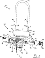
- Fig. 1 shows an exploded view of an embodiment of a two-wheel lock 10 according to the invention with alarm function.
- the two-wheel lock 10 comprises a lock body 22 and a securing bracket 12, which can be made in particular of metal.
- the securing bracket 12 of this embodiment is rigid and U-shaped and has a first end 14 and a second end 16 which can be inserted into the lock body 22.
- the securing bracket 12 on the in Fig. 1 shown front a first locking recess 18 and on the back (in Fig. 1 not visible) a second locking recess 20.
- the securing bracket 12 has a second locking recess 20 on the front and a first locking recess 18 on the rear.
- the first and the second locking recess 18, 20 can each cooperate with a locking mechanism 40 in order to lock the securing bracket 12 on the lock body 22.
- the lock body 22 comprises a tubular housing 26, which can be formed in particular from metal.
- the housing 26 has a first end 28 and a second end 30 on the longitudinal side. At the ends 28, 30, an access opening 32 is formed through which an interior 34 of the housing 26 is accessible. In an alternative embodiment, one of the access openings 32 can also be closed; in this case the housing 26 forms a cylinder open on one side. On the circumferential side, the housing 26 has close to its respective ends 28, 30 insertion openings 24.
- the ends 14, 16 of the securing bracket 12 can be guided into the interior 34 of the housing 26 through the insertion openings in order to close the two-wheel lock 10 and to lock the securing bracket 12 on the lock body 22.
- the interior 34 of the housing 26 houses the locking mechanism 40 and an alarm device 60.
- the locking mechanism 40 comprises a lock cylinder with a cylinder core 44, which can be rotated by an assigned key 42, a drive extension 46, a first bolt 50 and a second bolt 52.
- the cylinder core 44 is rotatably mounted in a cylinder housing 45.
- the locking cylinder can be designed, for example, as a plate cylinder with a plurality of plate tumblers, which enables a configuration in which the key 42 can be removed from the cylinder core 44 in two different rotational positions, in particular offset by 180 ° to one another.
- the locking cylinder is coupled via the drive extension 46 to the first bolt 50 and the second bolt 52 in order to drive the bolts 50, 52 for an unlocking movement or a locking movement.
- the drive extension 46 is arranged between the cylinder core 44 of the locking cylinder and the bolts 50, 52 and acts as a deflection device which deflects a rotary movement of the cylinder core 44 into a linear movement of the bolts 50, 52.
- the drive extension 46 has a plurality of eccentrically arranged pins 48 which can engage in corresponding guideways 54 of the first and second bolts 50, 52 in order to move them laterally when the cylinder core 44 rotates.
- the alarm device 60 comprises an acceleration sensor or vibration sensor (not shown) and a position detector 62 for determining the position of the locking mechanism 40.
- the position detector 62 can have, for example, a magnetic field sensor, a magnetic switch (e.g. a reed switch) or a contact switch.
- the position detector 62 determines, in particular, a position of a permanent magnet 64 arranged on the first latch 50.
- the measured value of the magnetic field strength is used to determine the position of the permanent magnet 64 and thus the position of the first latch 50 relative to the position detector 62.
- further permanent magnets can be provided, which can for example be connected to the second latch 52 in order to also detect the position of the second latch 52.
- embodiments are also conceivable that do without permanent magnets 64 in order to determine the position of the first bolt 50 and / or the second bolt 52 by means of the position detector 62, for example by using a contact switch.
- a contact switch can interact, for example, with an elevation on one of the bolts 50, 52 or with a cam of the drive extension 46.
- the alarm device 60 further comprises an energy source 66, for example one or more commercially available batteries and / or electrical accumulators, an evaluation and control circuit, an acoustic and / or optical signal transmitter, for example a loudspeaker and / or a light-emitting diode, and / or a radio transmitter unit for wireless transmission of an alarm signal (not shown).
- an energy source 66 for example one or more commercially available batteries and / or electrical accumulators
- an evaluation and control circuit for example acoustic and / or optical signal transmitter, for example a loudspeaker and / or a light-emitting diode, and / or a radio transmitter unit for wireless transmission of an alarm signal (not shown).
- the first end 28 and the second end 30 of the housing 26 are each closed by a first closure 70 and a second closure 72.
- the first closure 70 is a substantially semi-cylindrical carrier body.
- the carrier body is positively inserted along a cylindrical circumference into the access opening 32 of the housing 26 formed at the first end 28 of the housing 26.
- the first closure 70 has a first securing section 74 with an insertion opening 76, which in an assembled state of the first closure 70, in which the first closure 70 closes the first end 28 of the housing 26, is aligned with one of the insertion openings 24 of the housing 26.
- the first closure 70 comprises the cylinder housing 45, which forms a receptacle 78 in the carrier body, in which the cylinder core 44 is mounted.
- the alarm device 60 is essentially arranged in the second closure 72 of the housing 26.
- the second closure 72 is positively inserted into the access opening 32 of the housing 26 formed at the second end 30 of the housing 26.
- the second closure 72 is designed as an essentially cylindrical body, which removably closes the second end 30 of the housing 26 in an assembled state.
- the second closure 72 has a second securing section 80 with an insertion opening 82, which in the assembled state of the second closure 72 is aligned with one of the insertion openings 24 of the housing 26.
- the second closure 72 is non-positively locked against inadvertent loosening by at least one (in the case shown two) permanent magnets 84, which are arranged on an outside of the second closure 72 and can establish a magnetic connection with the material of the housing 26 the housing 26 secured.
- the first end 28 and the second end 30 of the housing 26 are surrounded on the outside by a respective protective cover 86.
- the protective sleeves 86 have insertion openings 88, which are aligned with the insertion openings 24 of the housing 26.
- the protective sleeves 86 can be designed as a cap and, for example, made of a flexible material, in particular plastic.
- the protective sleeves 86 are designed to be detachable, ie they can be removed from the housing 26 by pulling or pushing or pulled onto the housing 26.
- Fig. 2 shows a perspective view of the embodiment of FIG Fig. 1 , wherein the locking mechanism 40 is in an unlocked position.
- the housing 26 and the protective cover 86 have been removed to clarify the locking mechanism 40.
- the unlocked position neither the first bolt 50 nor the second bolt 52 of the locking mechanism 40 engages with the first and second locking recesses 18, 20 of the securing bracket 12.
- the securing bracket 12 is thus released for movement into the open position shown, in which it is completely released from the lock body 22 with its two ends 14, 16.
- the alarm device 60 is not activated in the unlocked position of the locking mechanism 40.
- the cylinder core 44 can be rotated by means of the key 42 either in a first direction of rotation or in an opposite second direction of rotation.
- the unlocking position thus forms a central position for the actuation of the locking cylinder in order to selectively bring the locking mechanism 40 or the locking cylinder into a different position.
- the lock cylinder or the cylinder core 44 can be brought into a first rotational position, corresponding to a first locking position, by a rotary actuation in the first direction of rotation (cf. Fig. 3 ).
- the lock cylinder or the cylinder core 44 can be brought into a second rotational position, corresponding to a second locking position, by a rotary actuation in the second direction of rotation (cf. Fig. 4 ).
- the first rotational position, the second rotational position and the third rotational position can each be offset by 90 ° to one another.
- the first rotational position of the cylinder core 44 can be offset by an angle of 90 ° with respect to the third rotational position
- the second rotational position of the cylinder core 44 with respect to the third rotational position by an angle of 90 ° and with respect to the first rotational position by an angle of 180 ° can be offset.
- the first bolt 50 and the second bolt 52 are each driven in opposite directions to one another both in the first direction of rotation and in the second direction of rotation.
- a similar, mutually opposite movement of the first and the second latch 50, 52 is provided, the user being able to select a desired locking position by means of the actuation direction.
- the opposite movement of the first and second bolts 50, 52 is brought about by the drive extension 46 of the locking cylinder, the pins 48 of which engage in the guideways 54 of the first and second bolts 50, 52 in order to laterally counteract these when the locking cylinder 44 is actuated move.
- Fig. 3 shows a perspective view of the embodiment of FIG Fig. 2 , wherein the locking mechanism 40 is in the first locking position.
- the securing bracket 12 assumes the closed position, its first end 14 engaging in the insertion opening 76 of the first closure 70 and its second end 16 engaging in the insertion opening 82 of the second closure 72.
- the first latch 50 stands with the first Locking recess 18 of the first end 14 of the securing bracket 12 engages, while the second latch 52 engages with the (rear) first locking recess 18 of the second end 16 of the securing bracket 12.
- the securing bracket is thus mechanically secured in the lock body 22 in the first locking position.
- the alarm device 60 is also not activated in the first locking position of the locking mechanism 40.
- Fig. 4 shows a perspective view of the embodiment of FIG Fig. 2 , wherein the locking mechanism 40 is, however, in the second locking position, which at the same time corresponds to an alarm activation position of the locking mechanism 40.
- the key 42 is opposite to the rotational position Fig. 3 rotated by 180 °.
- the first latch 50 engages with the second locking recess 20 of the second end 16 of the securing bracket 12, while the second latch 52 engages with the (rear) second locking recess 20 of the first end 14 of the securing bracket 12.
- a detection signal corresponding to the position of the first latch 50 is generated in the position detector 62, which can be forwarded, for example, to the evaluation and control circuit of the alarm device 60 in order to activate the alarm device 60.
- This activation of the alarm device 60 can take place immediately or with a time delay, for example in order to enable the authorized user to end a locking process.
- the securing bracket 14 is thus mechanically secured to the lock body 22 and is also protected against possible manipulation by the activated alarm device 60.
- the alarm device 60 can be transferred to a monitoring mode in which the alarm device 60 is based on the signals from the acceleration sensor or vibration sensor and For example, a comparison with a respective threshold value constantly checks whether an impermissible change in position or other movement has taken place. If applicable, the alarm device 60 outputs an acoustic and / or optical alarm signal. It can be provided that a pre-alarm signal is output first, a main alarm signal, which can be louder than the pre-alarm signal, for example, only after a main alarm delay interval has elapsed and as a result of a change in position that is still detected.
- the user can thus not only bring about a desired mechanical locking, but can also select in a simple manner whether the alarm device 60 should be activated or not.
- the locking mechanism 40 is brought into an alarm activation position by means of the assigned key 42, which is provided in addition to an unlocking position and a locking position of the locking mechanism 40.
- the key 42 can be inserted into the cylinder core 44 in three different positions of the cylinder core 44 and can be removed from the cylinder core 44, namely in the first locking position (alarm device 60 deactivated), in the second locking position (alarm activation position) and in the unlocking position.
- two different positions of the locking mechanism 40 can be selected, in which the assigned key 42 can be removed from the locking cylinder, the alarm device 60 being deactivated in one position and the alarm device 60 being activated in the other position.
- the locking mechanism 40 comprises a lock cylinder which can be actuated by an associated key 42 and has a cylinder core 44 and a drive extension 46.
- the lock cylinder could be replaced, for example, by an electric motor, which in particular has a reduction gear and an associated control device can have and can drive the drive extension 46 to a rotational movement. This can happen, for example, on the basis of a coded control signal which is transmitted by the authorized user by means of a radio remote control unit.
- the authorized user can indirectly select or control an activation state of the alarm device via the locking mechanism by moving the locking mechanism into an alarm activation position.
Landscapes
- Lock And Its Accessories (AREA)
- Emergency Alarm Devices (AREA)
- Burglar Alarm Systems (AREA)
- Professional, Industrial, Or Sporting Protective Garments (AREA)
- Adornments (AREA)
- Gloves (AREA)
Applications Claiming Priority (1)
| Application Number | Priority Date | Filing Date | Title |
|---|---|---|---|
| DE102018116434.3A DE102018116434A1 (de) | 2018-07-06 | 2018-07-06 | Zweiradschloss mit Alarmfunktion |
Publications (2)
| Publication Number | Publication Date |
|---|---|
| EP3591147A1 true EP3591147A1 (fr) | 2020-01-08 |
| EP3591147B1 EP3591147B1 (fr) | 2022-05-11 |
Family
ID=67180660
Family Applications (1)
| Application Number | Title | Priority Date | Filing Date |
|---|---|---|---|
| EP19184447.1A Active EP3591147B1 (fr) | 2018-07-06 | 2019-07-04 | Serrure de deux roues ayant une fonction d'alarme |
Country Status (6)
| Country | Link |
|---|---|
| US (1) | US11447976B2 (fr) |
| EP (1) | EP3591147B1 (fr) |
| CN (1) | CN110685513B (fr) |
| CA (1) | CA3047657A1 (fr) |
| DE (1) | DE102018116434A1 (fr) |
| TW (1) | TWI821322B (fr) |
Cited By (1)
| Publication number | Priority date | Publication date | Assignee | Title |
|---|---|---|---|---|
| US12012171B1 (en) * | 2023-02-15 | 2024-06-18 | Spencer Daulisa | Remote controller apparatus |
Families Citing this family (11)
| Publication number | Priority date | Publication date | Assignee | Title |
|---|---|---|---|---|
| DE102019123481A1 (de) * | 2019-09-02 | 2021-03-04 | ABUS August Bremicker Söhne Kommanditgesellschaft | Gelenkschloss |
| DE102021105647A1 (de) * | 2020-03-17 | 2021-09-23 | ABUS August Bremicker Söhne Kommanditgesellschaft | Schloss |
| DE102020116008A1 (de) * | 2020-06-17 | 2021-12-23 | ABUS August Bremicker Söhne Kommanditgesellschaft | Tragbares elektronisches Schloss |
| USD972913S1 (en) * | 2021-08-03 | 2022-12-20 | Wenzhou Ruicheng Trading Co Ltd | Car safety belt lock |
| DE102021122247A1 (de) | 2021-08-27 | 2023-03-02 | ABUS August Bremicker Söhne Kommanditgesellschaft | Elektromechanisches Schloss |
| DE102021125310A1 (de) | 2021-09-29 | 2023-03-30 | ABUS August Bremicker Söhne Kommanditgesellschaft | Bügelschloss |
| DE102022102480A1 (de) * | 2022-02-02 | 2023-08-03 | ABUS August Bremicker Söhne Kommanditgesellschaft | Klobenschloss |
| DE102022111846A1 (de) | 2022-05-11 | 2023-11-16 | ABUS August Bremicker Söhne Kommanditgesellschaft | Bügelschloss mit Aufschweißpanzerung |
| CN115522822A (zh) * | 2022-10-27 | 2022-12-27 | 浙江瑞泰动力有限公司 | 一种无钥匙化的智能电控锁 |
| USD1044471S1 (en) * | 2023-03-15 | 2024-10-01 | Wenzhou Jinjian Smart Lock Co., Ltd | U type combination lock |
| DE102023116135A1 (de) * | 2023-06-20 | 2024-12-24 | ABUS August Bremicker Söhne Kommanditgesellschaft | Klobenschloss |
Citations (17)
| Publication number | Priority date | Publication date | Assignee | Title |
|---|---|---|---|---|
| US5408212A (en) * | 1992-09-18 | 1995-04-18 | Brio Corporation | Multi-mode combination alarm and locking apparatus for bicycles, motorcycles and the like |
| CN2209200Y (zh) * | 1994-10-21 | 1995-10-04 | 昆明市五华科技开发服务部 | 自行车防盗报警锁 |
| EP0831198A1 (fr) * | 1996-09-18 | 1998-03-25 | Abus Aug. Bremicker Söhne Kg | Cadenas |
| WO1999032348A1 (fr) * | 1997-12-19 | 1999-07-01 | Allouche Joelle | Dispositif antivol de haute securite pour engins motorises |
| DE10026701A1 (de) | 2000-05-30 | 2001-12-06 | Bremicker Soehne Kg A | Bügelschloß |
| CN2576864Y (zh) * | 2002-10-11 | 2003-10-01 | 汤巍波 | 防盗报警车锁 |
| DE10252080A1 (de) | 2002-11-08 | 2004-05-27 | ABUS August Bremicker Söhne KG | Rahmenschloss |
| DE102005040066A1 (de) | 2005-08-24 | 2007-03-01 | ABUS August Bremicker Söhne KG | Gelenkschloss |
| DE102005043927A1 (de) | 2005-09-14 | 2007-03-22 | ABUS August Bremicker Söhne KG | Bremsscheibenschloss |
| DE102007035122A1 (de) | 2007-07-27 | 2009-01-29 | ABUS August Bremicker Söhne KG | Schloss |
| US20110259063A1 (en) * | 2008-03-27 | 2011-10-27 | Ivan Foti | Alarm lock |
| DE102011015313A1 (de) | 2011-03-29 | 2012-10-04 | ABUS August Bremicker Söhne KG | Rahmenschloss |
| DE102012002903A1 (de) | 2012-02-13 | 2013-08-14 | ABUS August Bremicker Söhne KG | Rahmenschloss |
| DE102014108355A1 (de) | 2014-06-13 | 2015-12-17 | ABUS August Bremicker Söhne KG | Zylinderschloss |
| US20160333607A1 (en) * | 2013-09-26 | 2016-11-17 | Michael Nicolaus Cagan | Transportable Device for Preventing a Loss of a Movable Object |
| CN106639681A (zh) * | 2016-12-19 | 2017-05-10 | 徐小强 | 一种遥控电子自行车锁 |
| EP3372762A1 (fr) * | 2017-03-09 | 2018-09-12 | ABUS August Bremicker Söhne KG | Cadenas à articulation pourvu de dispositif d'alarme |
Family Cites Families (23)
| Publication number | Priority date | Publication date | Assignee | Title |
|---|---|---|---|---|
| US4290279A (en) * | 1980-07-14 | 1981-09-22 | Unican Security Systems, Ltd. | Padlock with interchangeable cylinder |
| US4358943A (en) * | 1980-08-28 | 1982-11-16 | Benoit Ouellet | Vehicle door lock |
| US5398529A (en) * | 1991-03-07 | 1995-03-21 | Goldman; David S. | Tamper-resistant lock |
| US5417092A (en) * | 1994-06-02 | 1995-05-23 | Iu; Chien-Chzh | Padlock |
| US5561996A (en) * | 1994-08-30 | 1996-10-08 | Chang; Chao S. | Gearshift lock |
| CN2505555Y (zh) | 2001-09-18 | 2002-08-14 | 黄尊景 | 电子挂锁结构 |
| US6718802B2 (en) * | 2002-09-05 | 2004-04-13 | Robert A. Vito | Tamper resistant lock |
| US6761051B1 (en) * | 2003-02-27 | 2004-07-13 | Ez Trend Technology Co., Ltd. | Electric padlock |
| TWI224647B (en) * | 2003-04-03 | 2004-12-01 | Waterson Corp | A padlock device |
| EP1637679A1 (fr) * | 2004-09-21 | 2006-03-22 | Magnum Industries Limited | Cadenas, notamment pour bicyclettes |
| CN201125582Y (zh) | 2007-11-08 | 2008-10-01 | 严福煊 | 防盗报警锁 |
| US8225629B2 (en) * | 2008-04-18 | 2012-07-24 | Ingersoll Rand Company | Portable lock with electronic lock actuator |
| US7712340B2 (en) * | 2008-04-30 | 2010-05-11 | Wen-Kwei Chang | Lock structure |
| TW200951285A (en) | 2008-06-04 | 2009-12-16 | Tzen-Liea Chow | Alarm padlock |
| US7921682B1 (en) | 2009-12-15 | 2011-04-12 | Jieh-Jung Chang | Padlock with alarm function |
| ITMI20120213U1 (it) | 2012-06-04 | 2013-12-05 | Maggi Catene Spa | Dispositivo antifurto allarmato. |
| US9115511B1 (en) | 2012-08-08 | 2015-08-25 | Donald M. Schmidt | Padlock with alarm and shackle locking mechanism |
| CN203961522U (zh) | 2014-07-29 | 2014-11-26 | 林滨海 | 包樑报警锁 |
| CN105113873A (zh) | 2015-08-17 | 2015-12-02 | 四川迪意创意科技有限公司 | 一种智能u型锁 |
| CN105350839B (zh) * | 2015-11-26 | 2017-11-24 | 牟鑫磊 | 一种智能防盗报警锁的报警控制方法 |
| TWI637099B (zh) * | 2016-10-04 | 2018-10-01 | 萊能科技私人有限公司 | 掛鎖 |
| CN206091637U (zh) | 2016-10-12 | 2017-04-12 | 广州市亿汇五金电子有限公司 | 电子防盗圆管锁 |
| CN207513365U (zh) | 2017-10-27 | 2018-06-19 | 无锡创革科技有限公司 | 一种可用智能设备远程控制的自行车锁 |
-
2018
- 2018-07-06 DE DE102018116434.3A patent/DE102018116434A1/de not_active Withdrawn
-
2019
- 2019-06-21 CA CA3047657A patent/CA3047657A1/fr active Pending
- 2019-07-01 US US16/458,865 patent/US11447976B2/en active Active
- 2019-07-01 TW TW108123113A patent/TWI821322B/zh active
- 2019-07-04 EP EP19184447.1A patent/EP3591147B1/fr active Active
- 2019-07-05 CN CN201910605004.5A patent/CN110685513B/zh active Active
Patent Citations (17)
| Publication number | Priority date | Publication date | Assignee | Title |
|---|---|---|---|---|
| US5408212A (en) * | 1992-09-18 | 1995-04-18 | Brio Corporation | Multi-mode combination alarm and locking apparatus for bicycles, motorcycles and the like |
| CN2209200Y (zh) * | 1994-10-21 | 1995-10-04 | 昆明市五华科技开发服务部 | 自行车防盗报警锁 |
| EP0831198A1 (fr) * | 1996-09-18 | 1998-03-25 | Abus Aug. Bremicker Söhne Kg | Cadenas |
| WO1999032348A1 (fr) * | 1997-12-19 | 1999-07-01 | Allouche Joelle | Dispositif antivol de haute securite pour engins motorises |
| DE10026701A1 (de) | 2000-05-30 | 2001-12-06 | Bremicker Soehne Kg A | Bügelschloß |
| CN2576864Y (zh) * | 2002-10-11 | 2003-10-01 | 汤巍波 | 防盗报警车锁 |
| DE10252080A1 (de) | 2002-11-08 | 2004-05-27 | ABUS August Bremicker Söhne KG | Rahmenschloss |
| DE102005040066A1 (de) | 2005-08-24 | 2007-03-01 | ABUS August Bremicker Söhne KG | Gelenkschloss |
| DE102005043927A1 (de) | 2005-09-14 | 2007-03-22 | ABUS August Bremicker Söhne KG | Bremsscheibenschloss |
| DE102007035122A1 (de) | 2007-07-27 | 2009-01-29 | ABUS August Bremicker Söhne KG | Schloss |
| US20110259063A1 (en) * | 2008-03-27 | 2011-10-27 | Ivan Foti | Alarm lock |
| DE102011015313A1 (de) | 2011-03-29 | 2012-10-04 | ABUS August Bremicker Söhne KG | Rahmenschloss |
| DE102012002903A1 (de) | 2012-02-13 | 2013-08-14 | ABUS August Bremicker Söhne KG | Rahmenschloss |
| US20160333607A1 (en) * | 2013-09-26 | 2016-11-17 | Michael Nicolaus Cagan | Transportable Device for Preventing a Loss of a Movable Object |
| DE102014108355A1 (de) | 2014-06-13 | 2015-12-17 | ABUS August Bremicker Söhne KG | Zylinderschloss |
| CN106639681A (zh) * | 2016-12-19 | 2017-05-10 | 徐小强 | 一种遥控电子自行车锁 |
| EP3372762A1 (fr) * | 2017-03-09 | 2018-09-12 | ABUS August Bremicker Söhne KG | Cadenas à articulation pourvu de dispositif d'alarme |
Cited By (1)
| Publication number | Priority date | Publication date | Assignee | Title |
|---|---|---|---|---|
| US12012171B1 (en) * | 2023-02-15 | 2024-06-18 | Spencer Daulisa | Remote controller apparatus |
Also Published As
| Publication number | Publication date |
|---|---|
| CN110685513A (zh) | 2020-01-14 |
| EP3591147B1 (fr) | 2022-05-11 |
| DE102018116434A1 (de) | 2020-01-09 |
| US11447976B2 (en) | 2022-09-20 |
| US20200011087A1 (en) | 2020-01-09 |
| CN110685513B (zh) | 2022-04-26 |
| CA3047657A1 (fr) | 2020-01-06 |
| TW202006231A (zh) | 2020-02-01 |
| TWI821322B (zh) | 2023-11-11 |
Similar Documents
| Publication | Publication Date | Title |
|---|---|---|
| EP3591147A1 (fr) | Serrure de deux roues ayant une fonction d'alarme | |
| EP3372762B1 (fr) | Cadenas à articulation pourvu de dispositif d'alarme | |
| DE3853828T2 (de) | Verriegelungsvorrichtung. | |
| EP3288821B1 (fr) | Système d'immobilisation destiné à des deux-roues | |
| EP3617428B1 (fr) | Fermeture pour deux-roues | |
| DE3706600A1 (de) | Elektronisches schloss und schluesselsystem mit einer den schluessel identifizierenden funktion | |
| DE19654443A1 (de) | Verfahren und Vorrichtung zur Schließkontrolle von Schlössern | |
| EP3410412B1 (fr) | Dispositif d'alarme mobile | |
| EP3575520B1 (fr) | Cadenas à arceau | |
| EP3434850B1 (fr) | Serrure électronique pour deux roues | |
| DE69002786T2 (de) | Schloss mit einem elektronischen Schlüssel. | |
| EP4480797A1 (fr) | Serrure de cadre électronique | |
| EP3567194A1 (fr) | Cadenas à arceau électronique | |
| WO2013110459A1 (fr) | Dispositif de fermeture destiné à fermer et sécuriser un dispositif de réception | |
| EP3765688B1 (fr) | Ensemble ferrure pour un châssis de battant d'une fenêtre, fenêtre correspondante, procédé pour faire fonctionner un ensemble ferrure, procédé pour monter un ensemble ferrure et dispositif capteur | |
| DE102021116257A1 (de) | Sicherungssystem | |
| DE4315892C2 (de) | Schließsystem für anzeigende Schlüssel | |
| DE20320720U1 (de) | Schließzylinder | |
| DE102018126356A1 (de) | Rahmenschloss | |
| DE4434612B4 (de) | Schließsystem, insbesondere für Kraftfahrzeug | |
| DE102024124406A1 (de) | Sicherungsvorrichtung und Schloss | |
| DE102004048022B4 (de) | Vorrichtung zur Scharfschaltung und Unscharfschaltung einer Alarmanlage | |
| DE102023125116B3 (de) | Schloss, Schließanlage und Verfahren zum Betrieb eines Schlosses oder einer Schließanlage | |
| EP4303107B1 (fr) | Dispositif de rangement | |
| DE102019110347A1 (de) | Vorrichtung zum Erkennen von Zuständen eines Schlosses und/oder einer Tür |
Legal Events
| Date | Code | Title | Description |
|---|---|---|---|
| PUAI | Public reference made under article 153(3) epc to a published international application that has entered the european phase |
Free format text: ORIGINAL CODE: 0009012 |
|
| STAA | Information on the status of an ep patent application or granted ep patent |
Free format text: STATUS: THE APPLICATION HAS BEEN PUBLISHED |
|
| AK | Designated contracting states |
Kind code of ref document: A1 Designated state(s): AL AT BE BG CH CY CZ DE DK EE ES FI FR GB GR HR HU IE IS IT LI LT LU LV MC MK MT NL NO PL PT RO RS SE SI SK SM TR |
|
| AX | Request for extension of the european patent |
Extension state: BA ME |
|
| STAA | Information on the status of an ep patent application or granted ep patent |
Free format text: STATUS: REQUEST FOR EXAMINATION WAS MADE |
|
| 17P | Request for examination filed |
Effective date: 20200708 |
|
| RBV | Designated contracting states (corrected) |
Designated state(s): AL AT BE BG CH CY CZ DE DK EE ES FI FR GB GR HR HU IE IS IT LI LT LU LV MC MK MT NL NO PL PT RO RS SE SI SK SM TR |
|
| STAA | Information on the status of an ep patent application or granted ep patent |
Free format text: STATUS: EXAMINATION IS IN PROGRESS |
|
| RIC1 | Information provided on ipc code assigned before grant |
Ipc: E05B 45/00 20060101AFI20210125BHEP Ipc: E05B 47/00 20060101ALN20210125BHEP Ipc: E05B 71/00 20060101ALI20210125BHEP Ipc: E05B 67/24 20060101ALN20210125BHEP |
|
| 17Q | First examination report despatched |
Effective date: 20210209 |
|
| GRAP | Despatch of communication of intention to grant a patent |
Free format text: ORIGINAL CODE: EPIDOSNIGR1 |
|
| STAA | Information on the status of an ep patent application or granted ep patent |
Free format text: STATUS: GRANT OF PATENT IS INTENDED |
|
| RIC1 | Information provided on ipc code assigned before grant |
Ipc: E05B 47/00 20060101ALN20211022BHEP Ipc: E05B 67/24 20060101ALN20211022BHEP Ipc: E05B 71/00 20060101ALI20211022BHEP Ipc: E05B 45/00 20060101AFI20211022BHEP |
|
| GRAJ | Information related to disapproval of communication of intention to grant by the applicant or resumption of examination proceedings by the epo deleted |
Free format text: ORIGINAL CODE: EPIDOSDIGR1 |
|
| STAA | Information on the status of an ep patent application or granted ep patent |
Free format text: STATUS: EXAMINATION IS IN PROGRESS |
|
| INTG | Intention to grant announced |
Effective date: 20211124 |
|
| INTC | Intention to grant announced (deleted) | ||
| RIC1 | Information provided on ipc code assigned before grant |
Ipc: E05B 47/00 20060101ALN20211214BHEP Ipc: E05B 67/24 20060101ALN20211214BHEP Ipc: E05B 71/00 20060101ALI20211214BHEP Ipc: E05B 45/00 20060101AFI20211214BHEP |
|
| GRAP | Despatch of communication of intention to grant a patent |
Free format text: ORIGINAL CODE: EPIDOSNIGR1 |
|
| STAA | Information on the status of an ep patent application or granted ep patent |
Free format text: STATUS: GRANT OF PATENT IS INTENDED |
|
| INTG | Intention to grant announced |
Effective date: 20220126 |
|
| GRAS | Grant fee paid |
Free format text: ORIGINAL CODE: EPIDOSNIGR3 |
|
| GRAA | (expected) grant |
Free format text: ORIGINAL CODE: 0009210 |
|
| STAA | Information on the status of an ep patent application or granted ep patent |
Free format text: STATUS: THE PATENT HAS BEEN GRANTED |
|
| AK | Designated contracting states |
Kind code of ref document: B1 Designated state(s): AL AT BE BG CH CY CZ DE DK EE ES FI FR GB GR HR HU IE IS IT LI LT LU LV MC MK MT NL NO PL PT RO RS SE SI SK SM TR |
|
| REG | Reference to a national code |
Ref country code: GB Ref legal event code: FG4D Free format text: NOT ENGLISH |
|
| REG | Reference to a national code |
Ref country code: CH Ref legal event code: EP |
|
| REG | Reference to a national code |
Ref country code: AT Ref legal event code: REF Ref document number: 1491537 Country of ref document: AT Kind code of ref document: T Effective date: 20220515 |
|
| REG | Reference to a national code |
Ref country code: DE Ref legal event code: R096 Ref document number: 502019004321 Country of ref document: DE |
|
| REG | Reference to a national code |
Ref country code: IE Ref legal event code: FG4D Free format text: LANGUAGE OF EP DOCUMENT: GERMAN |
|
| REG | Reference to a national code |
Ref country code: LT Ref legal event code: MG9D |
|
| REG | Reference to a national code |
Ref country code: NL Ref legal event code: MP Effective date: 20220511 |
|
| PG25 | Lapsed in a contracting state [announced via postgrant information from national office to epo] |
Ref country code: SE Free format text: LAPSE BECAUSE OF FAILURE TO SUBMIT A TRANSLATION OF THE DESCRIPTION OR TO PAY THE FEE WITHIN THE PRESCRIBED TIME-LIMIT Effective date: 20220511 Ref country code: PT Free format text: LAPSE BECAUSE OF FAILURE TO SUBMIT A TRANSLATION OF THE DESCRIPTION OR TO PAY THE FEE WITHIN THE PRESCRIBED TIME-LIMIT Effective date: 20220912 Ref country code: NO Free format text: LAPSE BECAUSE OF FAILURE TO SUBMIT A TRANSLATION OF THE DESCRIPTION OR TO PAY THE FEE WITHIN THE PRESCRIBED TIME-LIMIT Effective date: 20220811 Ref country code: NL Free format text: LAPSE BECAUSE OF FAILURE TO SUBMIT A TRANSLATION OF THE DESCRIPTION OR TO PAY THE FEE WITHIN THE PRESCRIBED TIME-LIMIT Effective date: 20220511 Ref country code: LT Free format text: LAPSE BECAUSE OF FAILURE TO SUBMIT A TRANSLATION OF THE DESCRIPTION OR TO PAY THE FEE WITHIN THE PRESCRIBED TIME-LIMIT Effective date: 20220511 Ref country code: HR Free format text: LAPSE BECAUSE OF FAILURE TO SUBMIT A TRANSLATION OF THE DESCRIPTION OR TO PAY THE FEE WITHIN THE PRESCRIBED TIME-LIMIT Effective date: 20220511 Ref country code: FI Free format text: LAPSE BECAUSE OF FAILURE TO SUBMIT A TRANSLATION OF THE DESCRIPTION OR TO PAY THE FEE WITHIN THE PRESCRIBED TIME-LIMIT Effective date: 20220511 Ref country code: ES Free format text: LAPSE BECAUSE OF FAILURE TO SUBMIT A TRANSLATION OF THE DESCRIPTION OR TO PAY THE FEE WITHIN THE PRESCRIBED TIME-LIMIT Effective date: 20220511 Ref country code: BG Free format text: LAPSE BECAUSE OF FAILURE TO SUBMIT A TRANSLATION OF THE DESCRIPTION OR TO PAY THE FEE WITHIN THE PRESCRIBED TIME-LIMIT Effective date: 20220811 |
|
| PG25 | Lapsed in a contracting state [announced via postgrant information from national office to epo] |
Ref country code: RS Free format text: LAPSE BECAUSE OF FAILURE TO SUBMIT A TRANSLATION OF THE DESCRIPTION OR TO PAY THE FEE WITHIN THE PRESCRIBED TIME-LIMIT Effective date: 20220511 Ref country code: PL Free format text: LAPSE BECAUSE OF FAILURE TO SUBMIT A TRANSLATION OF THE DESCRIPTION OR TO PAY THE FEE WITHIN THE PRESCRIBED TIME-LIMIT Effective date: 20220511 Ref country code: LV Free format text: LAPSE BECAUSE OF FAILURE TO SUBMIT A TRANSLATION OF THE DESCRIPTION OR TO PAY THE FEE WITHIN THE PRESCRIBED TIME-LIMIT Effective date: 20220511 Ref country code: IS Free format text: LAPSE BECAUSE OF FAILURE TO SUBMIT A TRANSLATION OF THE DESCRIPTION OR TO PAY THE FEE WITHIN THE PRESCRIBED TIME-LIMIT Effective date: 20220911 |
|
| PG25 | Lapsed in a contracting state [announced via postgrant information from national office to epo] |
Ref country code: SM Free format text: LAPSE BECAUSE OF FAILURE TO SUBMIT A TRANSLATION OF THE DESCRIPTION OR TO PAY THE FEE WITHIN THE PRESCRIBED TIME-LIMIT Effective date: 20220511 Ref country code: SK Free format text: LAPSE BECAUSE OF FAILURE TO SUBMIT A TRANSLATION OF THE DESCRIPTION OR TO PAY THE FEE WITHIN THE PRESCRIBED TIME-LIMIT Effective date: 20220511 Ref country code: RO Free format text: LAPSE BECAUSE OF FAILURE TO SUBMIT A TRANSLATION OF THE DESCRIPTION OR TO PAY THE FEE WITHIN THE PRESCRIBED TIME-LIMIT Effective date: 20220511 Ref country code: EE Free format text: LAPSE BECAUSE OF FAILURE TO SUBMIT A TRANSLATION OF THE DESCRIPTION OR TO PAY THE FEE WITHIN THE PRESCRIBED TIME-LIMIT Effective date: 20220511 Ref country code: DK Free format text: LAPSE BECAUSE OF FAILURE TO SUBMIT A TRANSLATION OF THE DESCRIPTION OR TO PAY THE FEE WITHIN THE PRESCRIBED TIME-LIMIT Effective date: 20220511 Ref country code: CZ Free format text: LAPSE BECAUSE OF FAILURE TO SUBMIT A TRANSLATION OF THE DESCRIPTION OR TO PAY THE FEE WITHIN THE PRESCRIBED TIME-LIMIT Effective date: 20220511 |
|
| REG | Reference to a national code |
Ref country code: DE Ref legal event code: R097 Ref document number: 502019004321 Country of ref document: DE |
|
| PG25 | Lapsed in a contracting state [announced via postgrant information from national office to epo] |
Ref country code: MC Free format text: LAPSE BECAUSE OF FAILURE TO SUBMIT A TRANSLATION OF THE DESCRIPTION OR TO PAY THE FEE WITHIN THE PRESCRIBED TIME-LIMIT Effective date: 20220511 |
|
| REG | Reference to a national code |
Ref country code: CH Ref legal event code: PL |
|
| PLBE | No opposition filed within time limit |
Free format text: ORIGINAL CODE: 0009261 |
|
| STAA | Information on the status of an ep patent application or granted ep patent |
Free format text: STATUS: NO OPPOSITION FILED WITHIN TIME LIMIT |
|
| REG | Reference to a national code |
Ref country code: BE Ref legal event code: MM Effective date: 20220731 |
|
| PG25 | Lapsed in a contracting state [announced via postgrant information from national office to epo] |
Ref country code: AL Free format text: LAPSE BECAUSE OF FAILURE TO SUBMIT A TRANSLATION OF THE DESCRIPTION OR TO PAY THE FEE WITHIN THE PRESCRIBED TIME-LIMIT Effective date: 20220511 |
|
| 26N | No opposition filed |
Effective date: 20230214 |
|
| PG25 | Lapsed in a contracting state [announced via postgrant information from national office to epo] |
Ref country code: LU Free format text: LAPSE BECAUSE OF NON-PAYMENT OF DUE FEES Effective date: 20220704 Ref country code: LI Free format text: LAPSE BECAUSE OF NON-PAYMENT OF DUE FEES Effective date: 20220731 Ref country code: FR Free format text: LAPSE BECAUSE OF NON-PAYMENT OF DUE FEES Effective date: 20220711 Ref country code: CH Free format text: LAPSE BECAUSE OF NON-PAYMENT OF DUE FEES Effective date: 20220731 |
|
| PG25 | Lapsed in a contracting state [announced via postgrant information from national office to epo] |
Ref country code: SI Free format text: LAPSE BECAUSE OF FAILURE TO SUBMIT A TRANSLATION OF THE DESCRIPTION OR TO PAY THE FEE WITHIN THE PRESCRIBED TIME-LIMIT Effective date: 20220511 Ref country code: BE Free format text: LAPSE BECAUSE OF NON-PAYMENT OF DUE FEES Effective date: 20220731 |
|
| PG25 | Lapsed in a contracting state [announced via postgrant information from national office to epo] |
Ref country code: IE Free format text: LAPSE BECAUSE OF NON-PAYMENT OF DUE FEES Effective date: 20220704 |
|
| PG25 | Lapsed in a contracting state [announced via postgrant information from national office to epo] |
Ref country code: IT Free format text: LAPSE BECAUSE OF FAILURE TO SUBMIT A TRANSLATION OF THE DESCRIPTION OR TO PAY THE FEE WITHIN THE PRESCRIBED TIME-LIMIT Effective date: 20220511 |
|
| PG25 | Lapsed in a contracting state [announced via postgrant information from national office to epo] |
Ref country code: HU Free format text: LAPSE BECAUSE OF FAILURE TO SUBMIT A TRANSLATION OF THE DESCRIPTION OR TO PAY THE FEE WITHIN THE PRESCRIBED TIME-LIMIT; INVALID AB INITIO Effective date: 20190704 |
|
| PG25 | Lapsed in a contracting state [announced via postgrant information from national office to epo] |
Ref country code: MK Free format text: LAPSE BECAUSE OF FAILURE TO SUBMIT A TRANSLATION OF THE DESCRIPTION OR TO PAY THE FEE WITHIN THE PRESCRIBED TIME-LIMIT Effective date: 20220511 Ref country code: CY Free format text: LAPSE BECAUSE OF FAILURE TO SUBMIT A TRANSLATION OF THE DESCRIPTION OR TO PAY THE FEE WITHIN THE PRESCRIBED TIME-LIMIT Effective date: 20220511 |
|
| PG25 | Lapsed in a contracting state [announced via postgrant information from national office to epo] |
Ref country code: MT Free format text: LAPSE BECAUSE OF FAILURE TO SUBMIT A TRANSLATION OF THE DESCRIPTION OR TO PAY THE FEE WITHIN THE PRESCRIBED TIME-LIMIT Effective date: 20220511 |
|
| PG25 | Lapsed in a contracting state [announced via postgrant information from national office to epo] |
Ref country code: BG Free format text: LAPSE BECAUSE OF FAILURE TO SUBMIT A TRANSLATION OF THE DESCRIPTION OR TO PAY THE FEE WITHIN THE PRESCRIBED TIME-LIMIT Effective date: 20220511 |
|
| PG25 | Lapsed in a contracting state [announced via postgrant information from national office to epo] |
Ref country code: BG Free format text: LAPSE BECAUSE OF FAILURE TO SUBMIT A TRANSLATION OF THE DESCRIPTION OR TO PAY THE FEE WITHIN THE PRESCRIBED TIME-LIMIT Effective date: 20220511 |
|
| PG25 | Lapsed in a contracting state [announced via postgrant information from national office to epo] |
Ref country code: GR Free format text: LAPSE BECAUSE OF NON-PAYMENT OF DUE FEES Effective date: 20220511 |
|
| PG25 | Lapsed in a contracting state [announced via postgrant information from national office to epo] |
Ref country code: GR Free format text: LAPSE BECAUSE OF NON-PAYMENT OF DUE FEES Effective date: 20220511 |
|
| REG | Reference to a national code |
Ref country code: AT Ref legal event code: MM01 Ref document number: 1491537 Country of ref document: AT Kind code of ref document: T Effective date: 20240704 |
|
| PGFP | Annual fee paid to national office [announced via postgrant information from national office to epo] |
Ref country code: GB Payment date: 20250722 Year of fee payment: 7 |
|
| PG25 | Lapsed in a contracting state [announced via postgrant information from national office to epo] |
Ref country code: AT Free format text: LAPSE BECAUSE OF NON-PAYMENT OF DUE FEES Effective date: 20240704 |
|
| PG25 | Lapsed in a contracting state [announced via postgrant information from national office to epo] |
Ref country code: TR Free format text: LAPSE BECAUSE OF FAILURE TO SUBMIT A TRANSLATION OF THE DESCRIPTION OR TO PAY THE FEE WITHIN THE PRESCRIBED TIME-LIMIT Effective date: 20220511 |
|
| PGFP | Annual fee paid to national office [announced via postgrant information from national office to epo] |
Ref country code: DE Payment date: 20250926 Year of fee payment: 7 |
|
| PGFP | Annual fee paid to national office [announced via postgrant information from national office to epo] |
Ref country code: AT Payment date: 20260410 Year of fee payment: 5 |