EP3591204B1 - Inverseur de poussée avec corps mobile de bord de fuite - Google Patents
Inverseur de poussée avec corps mobile de bord de fuite Download PDFInfo
- Publication number
- EP3591204B1 EP3591204B1 EP19183367.2A EP19183367A EP3591204B1 EP 3591204 B1 EP3591204 B1 EP 3591204B1 EP 19183367 A EP19183367 A EP 19183367A EP 3591204 B1 EP3591204 B1 EP 3591204B1
- Authority
- EP
- European Patent Office
- Prior art keywords
- thrust reverser
- trailing edge
- edge body
- assembly
- reverser doors
- Prior art date
- Legal status (The legal status is an assumption and is not a legal conclusion. Google has not performed a legal analysis and makes no representation as to the accuracy of the status listed.)
- Active
Links
Images




Classifications
-
- F—MECHANICAL ENGINEERING; LIGHTING; HEATING; WEAPONS; BLASTING
- F02—COMBUSTION ENGINES; HOT-GAS OR COMBUSTION-PRODUCT ENGINE PLANTS
- F02K—JET-PROPULSION PLANTS
- F02K1/00—Plants characterised by the form or arrangement of the jet pipe or nozzle; Jet pipes or nozzles peculiar thereto
- F02K1/54—Nozzles having means for reversing jet thrust
- F02K1/64—Reversing fan flow
- F02K1/70—Reversing fan flow using thrust reverser flaps or doors mounted on the fan housing
-
- F—MECHANICAL ENGINEERING; LIGHTING; HEATING; WEAPONS; BLASTING
- F02—COMBUSTION ENGINES; HOT-GAS OR COMBUSTION-PRODUCT ENGINE PLANTS
- F02K—JET-PROPULSION PLANTS
- F02K1/00—Plants characterised by the form or arrangement of the jet pipe or nozzle; Jet pipes or nozzles peculiar thereto
- F02K1/54—Nozzles having means for reversing jet thrust
- F02K1/56—Reversing jet main flow
- F02K1/60—Reversing jet main flow by blocking the rearward discharge by means of pivoted eyelids or clamshells, e.g. target-type reversers
-
- F—MECHANICAL ENGINEERING; LIGHTING; HEATING; WEAPONS; BLASTING
- F02—COMBUSTION ENGINES; HOT-GAS OR COMBUSTION-PRODUCT ENGINE PLANTS
- F02K—JET-PROPULSION PLANTS
- F02K1/00—Plants characterised by the form or arrangement of the jet pipe or nozzle; Jet pipes or nozzles peculiar thereto
- F02K1/54—Nozzles having means for reversing jet thrust
- F02K1/56—Reversing jet main flow
- F02K1/60—Reversing jet main flow by blocking the rearward discharge by means of pivoted eyelids or clamshells, e.g. target-type reversers
- F02K1/605—Reversing jet main flow by blocking the rearward discharge by means of pivoted eyelids or clamshells, e.g. target-type reversers the aft end of the engine cowling being movable to uncover openings for the reversed flow
-
- F—MECHANICAL ENGINEERING; LIGHTING; HEATING; WEAPONS; BLASTING
- F02—COMBUSTION ENGINES; HOT-GAS OR COMBUSTION-PRODUCT ENGINE PLANTS
- F02K—JET-PROPULSION PLANTS
- F02K1/00—Plants characterised by the form or arrangement of the jet pipe or nozzle; Jet pipes or nozzles peculiar thereto
- F02K1/54—Nozzles having means for reversing jet thrust
- F02K1/76—Control or regulation of thrust reversers
- F02K1/763—Control or regulation of thrust reversers with actuating systems or actuating devices; Arrangement of actuators for thrust reversers
-
- F—MECHANICAL ENGINEERING; LIGHTING; HEATING; WEAPONS; BLASTING
- F05—INDEXING SCHEMES RELATING TO ENGINES OR PUMPS IN VARIOUS SUBCLASSES OF CLASSES F01-F04
- F05D—INDEXING SCHEME FOR ASPECTS RELATING TO NON-POSITIVE-DISPLACEMENT MACHINES OR ENGINES, GAS-TURBINES OR JET-PROPULSION PLANTS
- F05D2250/00—Geometry
- F05D2250/40—Movement of components
- F05D2250/41—Movement of components with one degree of freedom
- F05D2250/411—Movement of components with one degree of freedom in rotation
-
- F—MECHANICAL ENGINEERING; LIGHTING; HEATING; WEAPONS; BLASTING
- F05—INDEXING SCHEMES RELATING TO ENGINES OR PUMPS IN VARIOUS SUBCLASSES OF CLASSES F01-F04
- F05D—INDEXING SCHEME FOR ASPECTS RELATING TO NON-POSITIVE-DISPLACEMENT MACHINES OR ENGINES, GAS-TURBINES OR JET-PROPULSION PLANTS
- F05D2260/00—Function
- F05D2260/50—Kinematic linkage, i.e. transmission of position
Definitions
- This disclosure relates generally to an aircraft propulsion system and, more particularly, to a thrust reverser for an aircraft propulsion system.
- FIG. 9 illustrates an aircraft propulsion system 900 with a known target-type thrust reverser 902 in a stowed position.
- FIG. 10 illustrates the aircraft propulsion system 900 with the target-type thrust reverser 902 in a deployed position. While such known thrust reversers have various benefits, these thrust reversers typically require the thrust reverser doors 904 to be positioned relatively far forward axially and, thus, increase the axial overall length of the propulsion system's nacelle. There is a need in the art for a thrust reverser arrangement enabling a more axially compact nacelle.
- GB 2 252 279 A discloses a prior art assembly for an aircraft propulsion system having the features of the preamble to claim 1.
- US 3 020 712 A discloses prior art reversible-thrust sound suppression jet nozzles with movable ejector rings.
- the present invention provides an assembly for an aircraft propulsion system as claimed in claim 1.
- FIG. 1 is a perspective illustration of an aircraft propulsion system 20 for an aircraft such as, but not limited to, a commercial airliner or cargo plane.
- This propulsion system 20 includes a nacelle 22 and a gas turbine engine.
- the gas turbine engine may be configured as a turbojet gas turbine engine; however, the present disclosure is not limited to such an exemplary gas turbine engine configuration.
- the nacelle 22 is configured to house and provide an aerodynamic cover for the gas turbine engine.
- the nacelle 22 extends along an axial centerline 24 of the aircraft propulsion system 20 between a nacelle upstream, forward end 26 and a nacelle downstream, aft end 28.
- the nacelle 22 of FIG. 1 includes a nacelle inlet structure 30, one or more cowls 32 (one such cowl visible in FIG. 1 ) and a nacelle aft structure 34, which is configured as part of or includes a thrust reverser 36 such as, but not limited to, a target-type thrust reverser.
- a thrust reverser 36 such as, but not limited to, a target-type thrust reverser.
- target-type thrust reverser and “clamshell-type thrust reverser” herein may both describe a thrust reverser with one or more (e.g., a pair of) outwardly pivoting doors.
- the doors of a target-type thrust reverser may redirect at least a hot gas stream and, in some embodiments, also a cold gas stream where the gas turbine engine is a turbofan gas turbine engine, for example.
- the inlet structure 30 is disposed at the nacelle forward end 26.
- the inlet structure 30 is configured to direct a stream of air through an inlet opening at the nacelle forward end 26 and into a forward-most stage (e.g., a low-pressure compressor (LPC) stage or a fan stage) of the gas turbine engine.
- a forward-most stage e.g., a low-pressure compressor (LPC) stage or a fan stage
- the cowls 32 are disposed axially between the inlet structure 30 and the aft structure 34.
- the cowls 32 are configured to provide an aerodynamic covering for a casing of the gas turbine engine.
- the aft structure 34 includes a fixed structure 38, one or more (e.g., an opposing pair of) thrust reverser doors 40 and 42 and a (e.g., tubular) trailing edge body 44.
- the aft structure 34 and its components are configured to form an aft portion of an outer aerodynamic flow surface 46 of the nacelle 22; see also FIG. 1 .
- the aft structure 34 and its components are configured to form an aft portion of an inner aerodynamic flow surface 48. This aft portion of the inner aerodynamic flow surface 48 forms an outer peripheral boundary of an aft-most portion of a gas path 50 within the aircraft propulsion system 20; e.g., a core gas path.
- This aft-most portion of the gas path 50 may receive a mixed gas flow (e.g., a mix of a core gas and/or bypass air) from an upstream portion (or portions) of the gas turbine engine; e.g., from a bypass duct and/or a low-pressure turbine (LPT) stage in a core of the gas turbine engine.
- the aft-most portion of the gas path 50 extends axially along the axial centerline 24 within the aircraft propulsion system 20 to an annular trailing edge 52 of a gas path nozzle 54 (e.g., a core nozzle), at which the gas path 50 meets an exterior environment surrounding the aircraft propulsion system 20.
- the fixed structure 38 is configured with a tubular body.
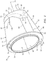
- the fixed structure 38 of FIGS. 2 and 3 extends circumferentially (e.g., completely) about the centerline 24.
- the fixed structure 38 extends axially along the centerline 24 between a fixed structure forward end 56 and a fixed structure aft end 58.
- the fixed structure 38 of FIGS. 2 and 3 is configured with a (e.g., tubular) fixed structure inner panel 60 and one or more fixed structure outer panels 62 (one visible in FIGS. 2 and 3 ).
- the inner panel 60 partially forms a respective portion of the inner aerodynamic flow surface 48.
- the outer panels 62 may be (e.g., diametrically) opposed from one another, and partially form the outer aerodynamic flow surface 46.
- Each outer panel 62 may have a generally rectangular or otherwise polygonal perimeter shape; however, the present disclosure is not limited to such an exemplary fixed structure configuration.
- the (e.g., upper) thrust reverser door 40 may be configured as a generally arcuate (e.g., conical) body.
- the thrust reverser door 40 of FIGS. 2 and 3 extends axially along the centerline 24 between a first (e.g., forward) door end 64 and a second (e.g., aft) door end 66.
- the thrust reverser door 40 extends circumferentially (e.g., between 150-180 degrees) about the centerline 24 between opposing door sides 68.
- the thrust reverser door 40 includes and extends radially between an inner arcuate (e.g., conical) panel 70 and an outer arcuate (e.g., conical) panel 72.
- the inner arcuate panel 70 is configured to define a respective portion of the inner aerodynamic surface 48 and, thus, a respective outer peripheral boundary portion of the gas path 50 when the door 40 is in its stowed position.
- the inner arcuate panel 70 is substantially flush with the inner panel 60 of the fixed structure 38.
- the outer arcuate panel 72 is configured to define a respective portion of the outer aerodynamic surface 46 when the door 40 is in its stowed position.
- the outer arcuate panel 72 is configured to circumferentially and axially overlap a portion of the fixed structure 38.
- the thrust reverser door 40 is pivotally attached to the fixed structure 38.
- the thrust reverser door 40 of FIGS. 2 and 3 for example, is attached to the fixed structure 38 by one or more pivot joints 74 (e.g., hinges). These pivot joints 74 are located at the opposing sides 68 of the thrust reverser door 40 at (e.g., on, adjacent or proximate) the second door end 66 and the fixed structure aft end 58.
- a first actuator 76 e.g., a hydraulic, pneumatic or mechanical linear actuator
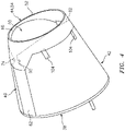
- the first actuator 76 is operable to move (e.g., pivot) the thrust reverser door 40 between the stowed position of FIGS. 2 and 4 and the deployed position of FIGS. 3 and 5 , where a first thrust reverser passage 78 is opened up between the fixed structure 38 and the door 40.
- the (e.g., low) thrust reverser door 42 may be configured as a generally arcuate (e.g., conical) body.
- the thrust reverser door 42 of FIGS. 2 and 3 extends axially along the centerline 24 between a first (e.g., forward) door end 80 and a second (e.g., aft) door end 82.
- the thrust reverser door 42 extends circumferentially (e.g., between 150-180 degrees) about the centerline 24 between opposing door sides 84.
- the thrust reverser door 42 includes and extends radially between an inner arcuate (e.g., conical) panel 86 and an outer arcuate (e.g., conical) panel 88.
- the inner arcuate panel 86 is configured to define a respective portion of the inner aerodynamic surface 48 and, thus, a respective outer peripheral boundary portion of the gas path 50 when the door 42 is in its stowed position.
- the inner arcuate panel 86 is substantially flush with the inner panel 60 of the fixed structure 38.
- the outer arcuate panel 88 is configured to define a respective portion of the outer aerodynamic surface 46 when the door 42 is in its stowed position.
- the outer arcuate panel 88 is configured to circumferentially and axially overlap a portion of the fixed structure 38.
- the thrust reverser door 42 is pivotally attached to the fixed structure 38.
- the thrust reverser door 42 of FIGS. 2 and 3 is attached to the fixed structure 38 by one or more pivot joints 90 (e.g., hinges). These pivot joints 90 are located at the opposing sides 84 of the thrust reverser door 42 at (e.g., on, adjacent or proximate) the second door end 82 and the fixed structure aft end 58.
- a second actuator 92 e.g., a hydraulic, pneumatic or mechanical linear actuator
- the second actuator 92 is operable to move (e.g., pivot) the thrust reverser door 42 between the stowed position of FIGS. 2 and 4 and the deployed position of FIGS. 3 and 5 , where a second thrust reverser passage 94 opposite the first thrust reverser passage 78 is opened up between the fixed structure 38 and the door 42.
- the trailing edge body 44 is configured to at least partially, here completely, form the nozzle 54 and its annular trailing edge 52.
- the trailing edge body 44 of FIGS. 2 and 3 extends axially from a first (e.g., forward) body end 96 to a second (e.g., aft) body end 98, which defines the annular trailing edge 52.
- the trailing edge body 44 extends circumferentially (e.g., completely) about the centerline 24.
- the trailing edge body 44 extends radially between an inner surface 100 and an outer surface 102.
- the inner surface 100 forms a respective (e.g., tubular) portion of the inner aerodynamic surface 48 when the thrust reverser doors 40 and 42 are in the stowed positions.
- the outer surface 102 forms a respective (e.g., tubular) portion of the outer aerodynamic surface 46 when the thrust reverser doors 40 and 42 are in the stowed positions.
- the trailing edge body 44 is pivotally attached to the thrust reverser door 42 by one or more pivot joints 104; e.g., hinges. These pivot joints 104 are circumferentially spaced from one another. The pivot joints 104 are located proximate the second door end 82.
- the trailing edge body 44 is coupled to the thrust reverser door 40 by one or more linkages 106; e.g., single, unitary link arms.
- the linkages 106 of FIGS. 3 and 5 are circumferentially displaced from one another about the centerline 24.
- Each linkage 106 extends between a first (e.g., forward) link arm end 108 and a second (e.g., aft) link arm end 110.
- Each linkage 106 is pivotally attached to the thrust reverser door 40 at the first link arm end 108.
- Each linkage 106 is pivotally attached to the trailing edge body 44 at the second link arm end 110.
- the trailing edge body 44 When in the stowed position, the trailing edge body 44 is configured to cover / overlap at least an aft portion of each thrust reverser door 40, 42.
- FIGS. 6A-6F illustrate a sequence of the thrust reverser 36 deploying, where the thrust reverser doors 40 and 42 and the trailing edge body 44 are stowed in FIG. 6A and the thrust reverser doors 40 and 42 and the trailing edge body 44 are deployed in FIG. 6F .
- the first and the second actuators 76 and 92 respectively push against the thrust reverser doors 40 and 42 causing the doors 40 and 42 to pivot about the pivot joints 74 and 90.
- the thrust reverser doors 40 and 42 pivot, a forward portion of each door 40, 42 projects radially outward into the surrounding environment and an aft portion of each door 40, 42 projects radially inward into the gas path 50.
- the aft portions of the doors 40, 42 are thereby operable to at least partially close off the gas path 50 proximate the nozzle 54, and redirect the gas flowing axially aft through the gas path 50 radially outward and forward through the thrust reverser passages 78 and 94.
- the trailing edge body 44 is displaced from a first position (when stowed; see FIG. 6A ) to a second position (when deployed; see FIG. 6F ).
- the displacement during the motion of FIGS. 6A-6F includes an axial component, a radial component as well as a pivotal component. More particularly, as the thrust reverser doors 40 and 42 open to the deployed position, the trailing edge body 44 is axially displaced aft, radially displaced along an upward (relative to position in figures) trajectory, and also pivoted in a clockwise direction. Note, the motion of the trailing edge body 44 is not limited to upward or clockwise movement as this relative movement will change depending upon the specific gravitational orientation of the doors 40 and 42 on the nacelle 22 and perspective of an observer.
- an axial centerline 112 of the body 44 is coaxial with the axial centerline 24.
- the axial centerline 112 of the body 44 is non-coaxial with the axial centerline 24.
- the axial centerline 112 may be displaced and/or angled relative to the axial centerline 24.
- the thrust reverser 36 may be configured such that the axial centerline 112 is displaced form, but not angle relative to (i.e., parallel to), the axial centerline 24 at the second position.
- the trailing edge body 44 may be configured to form one or more respective circumferential portions 114 of the nozzle 54 and its annular trailing edge 52.
- aft portions of the thrust reverser doors 40 and 42 may be configured to form one or more other circumferential portion 116, 118 of the nozzle 54 and its annular trailing edge 52.
Landscapes
- Engineering & Computer Science (AREA)
- Chemical & Material Sciences (AREA)
- Combustion & Propulsion (AREA)
- Mechanical Engineering (AREA)
- General Engineering & Computer Science (AREA)
- Structures Of Non-Positive Displacement Pumps (AREA)
- Power-Operated Mechanisms For Wings (AREA)
Claims (15)
- Ensemble pour un système de propulsion d'aéronef (20), comprenant :un inverseur de poussée comprenant une pluralité de portes d'inverseur de poussée (40, 42), chacune des portes d'inverseur de poussée (40, 42) étant configurée pour pivoter entre une position repliée et une position déployée ; etun corps de bord de fuite tubulaire (44) configuré pour former au moins partiellement une buse de trajet de gaz (54) pour le système de propulsion d'aéronef (20), le corps de bord de fuite tubulaire (44) étant configuré pour se déplacer d'une première position à une seconde position à mesure que les portes d'inverseur de poussée (40, 42) pivotent de la position repliée à la position déployée ;dans lequel une ligne centrale (112) du corps de bord de fuite tubulaire (44) est coaxiale avec une ligne centrale axiale (24) du système de propulsion d'aéronef (20) lorsque le corps de bord de fuite tubulaire (44) est dans la première position ;caractérisé en ce que :
la ligne centrale (112) du corps de bord de fuite tubulaire (44) n'est pas coaxiale avec la ligne centrale axiale (24) lorsque le corps de bord de fuite tubulaire (44) est dans la seconde position. - Ensemble selon la revendication 1, dans lequel l'inverseur de poussée est un inverseur de poussée à déflecteurs.
- Ensemble selon la revendication 1 ou 2, dans lequel le mouvement du corps de bord de fuite tubulaire (44) comprend un déplacement radial par rapport à la ligne centrale axiale (24) du système de propulsion d'aéronef (20).
- Ensemble selon une quelconque revendication précédente, dans lequel le mouvement du corps de bord de fuite tubulaire (44) comprend un déplacement axial par rapport à la ligne centrale axiale (24) du système de propulsion d'aéronef (20).
- Ensemble selon une quelconque revendication précédente, dans lequel le mouvement du corps de bord de fuite tubulaire (44) comprend un déplacement en pivotement.
- Ensemble selon une quelconque revendication précédente, comprenant en outre :une structure fixe (38) ;dans lequel chacune des portes d'inverseur de poussée (40, 42) est fixée de manière pivotante à la structure fixe (38) par une charnière respective (74, 90).
- Ensemble selon une quelconque revendication précédente, dans lequel :le corps de bord de fuite tubulaire (44) est fixé de manière pivotante à une première porte parmi les portes d'inverseur de poussée (42) par une charnière (104) ; etle corps de bord de fuite tubulaire (44) est couplé à une seconde porte parmi les portes d'inverseur de poussée (40) par une tringlerie (106) ; dans lequel, éventuellement :la tringlerie (106) est configurée sous forme d'un bras de liaison s'étendant entre une première extrémité de bras de liaison (108) et une seconde extrémité de bras de liaison (110) ;le bras de liaison est fixé de manière pivotante à la seconde porte parmi les portes d'inverseur de poussée (40) au niveau de la première extrémité de bras de liaison (108) ; etle bras de liaison est fixé de manière pivotante au corps de bord de fuite tubulaire (44) au niveau de la seconde extrémité de bras de liaison (110).
- Ensemble selon la revendication 7, dans lequel le corps de bord de fuite tubulaire (44) est en outre couplé à la seconde porte parmi les portes d'inverseur de poussée (40) par une seconde tringlerie (106), et la tringlerie (106) et la seconde tringlerie (106) sont écartées circonférentiellement l'une de l'autre.
- Ensemble selon une quelconque revendication précédente, dans lequel le corps de bord de fuite tubulaire (44) chevauche des parties arrière respectives des portes d'inverseur de poussée (40, 42) lorsque les portes d'inverseur de poussée (40, 42) sont dans la position repliée.
- Ensemble selon une quelconque revendication précédente, dans lequel le corps de bord de fuite tubulaire (44) est configuré pour former complètement un bord de fuite (52) de la buse de trajet de gaz (54).
- Ensemble selon l'une quelconque des revendications 1 à 9, dans lequel :le corps de bord de fuite tubulaire (44) est configuré pour former une première partie (114) d'un bord de fuite (52) de la buse de trajet de gaz (54) ; etune première porte parmi les portes d'inverseur de poussée (40, 42) est configurée pour former une seconde partie (116, 118) du bord de fuite (52).
- Ensemble selon l'une quelconque des revendications 1 à 9, dans lequelun trajet de gaz (50) s'étend à l'intérieur du système de propulsion d'aéronef (20) jusqu'à un bord de fuite (52) de la buse de trajet de gaz (54) ;chacune des portes d'inverseur de poussée (40, 42) est configurée pour former partiellement une limite périphérique externe du trajet de gaz (50) lorsqu'elle est dans la position repliée ; etle corps de bord de fuite tubulaire (44) est configuré pour former partiellement la limite périphérique externe du trajet de gaz (50) lorsque les portes d'inverseur de poussée (40, 42) sont dans la position repliée.
- Ensemble selon une quelconque revendication précédente, comprenant en outre une pluralité d'actionneurs (76, 92), chacun des actionneurs (76, 92) étant configuré pour faire pivoter une porte respective parmi les portes d'inverseur de poussée (40, 42) de la position repliée à la position déployée.
- Ensemble selon une quelconque revendication précédente, dans lequel les portes d'inverseur de poussée (40, 42) sont configurées pour rediriger un gaz sortant du système de propulsion d'aéronef (20).
- Ensemble selon une quelconque revendication précédente, dans lequel les portes d'inverseur de poussée (40, 42) sont configurées pour rediriger un gaz sortant d'un noyau du système de propulsion d'aéronef (20).
Applications Claiming Priority (1)
| Application Number | Priority Date | Filing Date | Title |
|---|---|---|---|
| US16/025,431 US11053887B2 (en) | 2018-07-02 | 2018-07-02 | Thrust reverser with displaceable trailing edge body |
Publications (2)
| Publication Number | Publication Date |
|---|---|
| EP3591204A1 EP3591204A1 (fr) | 2020-01-08 |
| EP3591204B1 true EP3591204B1 (fr) | 2022-10-05 |
Family
ID=67137700
Family Applications (1)
| Application Number | Title | Priority Date | Filing Date |
|---|---|---|---|
| EP19183367.2A Active EP3591204B1 (fr) | 2018-07-02 | 2019-06-28 | Inverseur de poussée avec corps mobile de bord de fuite |
Country Status (2)
| Country | Link |
|---|---|
| US (1) | US11053887B2 (fr) |
| EP (1) | EP3591204B1 (fr) |
Families Citing this family (5)
| Publication number | Priority date | Publication date | Assignee | Title |
|---|---|---|---|---|
| US12215530B2 (en) | 2022-06-10 | 2025-02-04 | Rohr, Inc. | Balk device for door lock |
| US12270356B2 (en) | 2022-08-01 | 2025-04-08 | Rohr, Inc. | Thrust reverser cascade with one or more flow disrupters |
| US12435682B2 (en) | 2022-08-01 | 2025-10-07 | Rohr, Inc. | Thrust reverser cascade with offset vane leading edges |
| US11873781B1 (en) | 2022-08-01 | 2024-01-16 | Rohr, Inc. | Thrust reverser cascade with one or more flow stabilizers |
| US12241433B2 (en) * | 2022-10-07 | 2025-03-04 | Rohr, Inc. | Thrust reverser system with angled door pivot axes |
Family Cites Families (14)
| Publication number | Priority date | Publication date | Assignee | Title |
|---|---|---|---|---|
| US3003312A (en) * | 1957-08-19 | 1961-10-10 | Thompson Ramo Wooldridge Inc | Exhaust nozzle for jet engines |
| US3020712A (en) | 1959-06-22 | 1962-02-13 | Boeing Co | Reversible-thrust sound suppression jet nozzles with movable ejector rings |
| US3036431A (en) | 1959-09-08 | 1962-05-29 | Boeing Co | Thrust reverser for jet engines |
| US3581841A (en) | 1970-07-27 | 1971-06-01 | Rohr Corp | Thrust reversing and noise suppressing apparatus for a jet engine |
| FR2486153B1 (fr) | 1980-07-04 | 1985-10-04 | Hurel Dubois Avions | Inverseur de poussee pour moteur a reaction, destine notamment a equiper un aeronef |
| GB2252279A (en) | 1991-02-01 | 1992-08-05 | Rolls Royce Plc | Thrust reverser |
| US5176340A (en) | 1991-11-26 | 1993-01-05 | Lair Jean Pierre | Thrust reverser with a planar exit opening |
| FR2742482B1 (fr) | 1995-12-19 | 1998-02-06 | Hurel Dubois Avions | Inverseur de poussee a tuyere a section reglable pour moteur d'avion a reaction |
| US6751944B2 (en) * | 2001-10-23 | 2004-06-22 | The Nordam Group, Inc. | Confluent variable exhaust nozzle |
| CA2486172C (fr) * | 2002-05-21 | 2010-11-09 | The Nordam Group, Inc. | Buse d'inverseur de poussee a surface variable |
| US8002217B2 (en) | 2007-11-16 | 2011-08-23 | Spirit Aerosystems, Inc. | System for adjustment of thrust reverser pivot door |
| US9739235B2 (en) * | 2014-03-21 | 2017-08-22 | Rohr, Inc. | Thrust reverser for a turbofan engine |
| US9938929B2 (en) * | 2014-03-21 | 2018-04-10 | Rohr, Inc. | Thrust reverser for a turbofan engine |
| US9964071B2 (en) * | 2015-01-13 | 2018-05-08 | Rohr, Inc. | Decoupled translating sleeve |
-
2018
- 2018-07-02 US US16/025,431 patent/US11053887B2/en active Active
-
2019
- 2019-06-28 EP EP19183367.2A patent/EP3591204B1/fr active Active
Also Published As
| Publication number | Publication date |
|---|---|
| EP3591204A1 (fr) | 2020-01-08 |
| US20200003156A1 (en) | 2020-01-02 |
| US11053887B2 (en) | 2021-07-06 |
Similar Documents
| Publication | Publication Date | Title |
|---|---|---|
| EP3591204B1 (fr) | Inverseur de poussée avec corps mobile de bord de fuite | |
| EP2660454B1 (fr) | Ensemble d'inverseur de poussée et procédé de fonctionnement | |
| EP3244051B1 (fr) | Moteur à turbine à gaz ayant un ensemble d'inverseur de poussée et procédé de fonctionnement | |
| EP3034848B1 (fr) | Moteur à turbine à gaz et son ensemble d'inverseur de poussée | |
| US10006405B2 (en) | Thrust reverser system with translating-rotating blocker doors and method of operation | |
| EP3244052B1 (fr) | Ensemble d'inverseur de poussée | |
| US11149686B2 (en) | Thrust reverser assembly | |
| EP3029306B1 (fr) | Moteur à turbine à gaz et son ensemble d'inverseur de poussée | |
| EP2921685B1 (fr) | Inverseur de poussée de réacteur double flux | |
| CN114651122B (zh) | 具有由装备有航空摇臂的机构控制的襟翼的推力反向器 | |
| EP4242444B1 (fr) | Inverseur de poussée pour tuyère à section variable | |
| EP3347587A1 (fr) | Ensemble inverseur de poussée | |
| EP3640466B1 (fr) | Inverseur de poussée | |
| EP3587783B1 (fr) | Étrésillon pliable | |
| US6050522A (en) | Thrust reverser for a high bypass turbofan engine | |
| EP4191047B1 (fr) | Buse à section variable et procédé de fonctionnement d'une buse à section variable | |
| US12158122B2 (en) | Nacelle for an aircraft propulsion assembly comprising a flap for closing a recess for the passage of an actuator |
Legal Events
| Date | Code | Title | Description |
|---|---|---|---|
| PUAI | Public reference made under article 153(3) epc to a published international application that has entered the european phase |
Free format text: ORIGINAL CODE: 0009012 |
|
| STAA | Information on the status of an ep patent application or granted ep patent |
Free format text: STATUS: THE APPLICATION HAS BEEN PUBLISHED |
|
| AK | Designated contracting states |
Kind code of ref document: A1 Designated state(s): AL AT BE BG CH CY CZ DE DK EE ES FI FR GB GR HR HU IE IS IT LI LT LU LV MC MK MT NL NO PL PT RO RS SE SI SK SM TR |
|
| STAA | Information on the status of an ep patent application or granted ep patent |
Free format text: STATUS: REQUEST FOR EXAMINATION WAS MADE |
|
| 17P | Request for examination filed |
Effective date: 20200708 |
|
| RBV | Designated contracting states (corrected) |
Designated state(s): AL AT BE BG CH CY CZ DE DK EE ES FI FR GB GR HR HU IE IS IT LI LT LU LV MC MK MT NL NO PL PT RO RS SE SI SK SM TR |
|
| GRAP | Despatch of communication of intention to grant a patent |
Free format text: ORIGINAL CODE: EPIDOSNIGR1 |
|
| STAA | Information on the status of an ep patent application or granted ep patent |
Free format text: STATUS: GRANT OF PATENT IS INTENDED |
|
| INTG | Intention to grant announced |
Effective date: 20220420 |
|
| GRAS | Grant fee paid |
Free format text: ORIGINAL CODE: EPIDOSNIGR3 |
|
| GRAA | (expected) grant |
Free format text: ORIGINAL CODE: 0009210 |
|
| STAA | Information on the status of an ep patent application or granted ep patent |
Free format text: STATUS: THE PATENT HAS BEEN GRANTED |
|
| AK | Designated contracting states |
Kind code of ref document: B1 Designated state(s): AL AT BE BG CH CY CZ DE DK EE ES FI FR GB GR HR HU IE IS IT LI LT LU LV MC MK MT NL NO PL PT RO RS SE SI SK SM TR |
|
| REG | Reference to a national code |
Ref country code: GB Ref legal event code: FG4D |
|
| REG | Reference to a national code |
Ref country code: CH Ref legal event code: EP |
|
| REG | Reference to a national code |
Ref country code: AT Ref legal event code: REF Ref document number: 1522885 Country of ref document: AT Kind code of ref document: T Effective date: 20221015 |
|
| REG | Reference to a national code |
Ref country code: DE Ref legal event code: R096 Ref document number: 602019020202 Country of ref document: DE |
|
| REG | Reference to a national code |
Ref country code: IE Ref legal event code: FG4D |
|
| REG | Reference to a national code |
Ref country code: LT Ref legal event code: MG9D |
|
| REG | Reference to a national code |
Ref country code: NL Ref legal event code: MP Effective date: 20221005 |
|
| REG | Reference to a national code |
Ref country code: AT Ref legal event code: MK05 Ref document number: 1522885 Country of ref document: AT Kind code of ref document: T Effective date: 20221005 |
|
| PG25 | Lapsed in a contracting state [announced via postgrant information from national office to epo] |
Ref country code: NL Free format text: LAPSE BECAUSE OF FAILURE TO SUBMIT A TRANSLATION OF THE DESCRIPTION OR TO PAY THE FEE WITHIN THE PRESCRIBED TIME-LIMIT Effective date: 20221005 |
|
| PG25 | Lapsed in a contracting state [announced via postgrant information from national office to epo] |
Ref country code: SE Free format text: LAPSE BECAUSE OF FAILURE TO SUBMIT A TRANSLATION OF THE DESCRIPTION OR TO PAY THE FEE WITHIN THE PRESCRIBED TIME-LIMIT Effective date: 20221005 Ref country code: PT Free format text: LAPSE BECAUSE OF FAILURE TO SUBMIT A TRANSLATION OF THE DESCRIPTION OR TO PAY THE FEE WITHIN THE PRESCRIBED TIME-LIMIT Effective date: 20230206 Ref country code: NO Free format text: LAPSE BECAUSE OF FAILURE TO SUBMIT A TRANSLATION OF THE DESCRIPTION OR TO PAY THE FEE WITHIN THE PRESCRIBED TIME-LIMIT Effective date: 20230105 Ref country code: LT Free format text: LAPSE BECAUSE OF FAILURE TO SUBMIT A TRANSLATION OF THE DESCRIPTION OR TO PAY THE FEE WITHIN THE PRESCRIBED TIME-LIMIT Effective date: 20221005 Ref country code: FI Free format text: LAPSE BECAUSE OF FAILURE TO SUBMIT A TRANSLATION OF THE DESCRIPTION OR TO PAY THE FEE WITHIN THE PRESCRIBED TIME-LIMIT Effective date: 20221005 Ref country code: ES Free format text: LAPSE BECAUSE OF FAILURE TO SUBMIT A TRANSLATION OF THE DESCRIPTION OR TO PAY THE FEE WITHIN THE PRESCRIBED TIME-LIMIT Effective date: 20221005 Ref country code: AT Free format text: LAPSE BECAUSE OF FAILURE TO SUBMIT A TRANSLATION OF THE DESCRIPTION OR TO PAY THE FEE WITHIN THE PRESCRIBED TIME-LIMIT Effective date: 20221005 |
|
| PG25 | Lapsed in a contracting state [announced via postgrant information from national office to epo] |
Ref country code: RS Free format text: LAPSE BECAUSE OF FAILURE TO SUBMIT A TRANSLATION OF THE DESCRIPTION OR TO PAY THE FEE WITHIN THE PRESCRIBED TIME-LIMIT Effective date: 20221005 Ref country code: PL Free format text: LAPSE BECAUSE OF FAILURE TO SUBMIT A TRANSLATION OF THE DESCRIPTION OR TO PAY THE FEE WITHIN THE PRESCRIBED TIME-LIMIT Effective date: 20221005 Ref country code: LV Free format text: LAPSE BECAUSE OF FAILURE TO SUBMIT A TRANSLATION OF THE DESCRIPTION OR TO PAY THE FEE WITHIN THE PRESCRIBED TIME-LIMIT Effective date: 20221005 Ref country code: IS Free format text: LAPSE BECAUSE OF FAILURE TO SUBMIT A TRANSLATION OF THE DESCRIPTION OR TO PAY THE FEE WITHIN THE PRESCRIBED TIME-LIMIT Effective date: 20230205 Ref country code: HR Free format text: LAPSE BECAUSE OF FAILURE TO SUBMIT A TRANSLATION OF THE DESCRIPTION OR TO PAY THE FEE WITHIN THE PRESCRIBED TIME-LIMIT Effective date: 20221005 Ref country code: GR Free format text: LAPSE BECAUSE OF FAILURE TO SUBMIT A TRANSLATION OF THE DESCRIPTION OR TO PAY THE FEE WITHIN THE PRESCRIBED TIME-LIMIT Effective date: 20230106 |
|
| REG | Reference to a national code |
Ref country code: DE Ref legal event code: R097 Ref document number: 602019020202 Country of ref document: DE |
|
| PG25 | Lapsed in a contracting state [announced via postgrant information from national office to epo] |
Ref country code: SM Free format text: LAPSE BECAUSE OF FAILURE TO SUBMIT A TRANSLATION OF THE DESCRIPTION OR TO PAY THE FEE WITHIN THE PRESCRIBED TIME-LIMIT Effective date: 20221005 Ref country code: RO Free format text: LAPSE BECAUSE OF FAILURE TO SUBMIT A TRANSLATION OF THE DESCRIPTION OR TO PAY THE FEE WITHIN THE PRESCRIBED TIME-LIMIT Effective date: 20221005 Ref country code: EE Free format text: LAPSE BECAUSE OF FAILURE TO SUBMIT A TRANSLATION OF THE DESCRIPTION OR TO PAY THE FEE WITHIN THE PRESCRIBED TIME-LIMIT Effective date: 20221005 Ref country code: DK Free format text: LAPSE BECAUSE OF FAILURE TO SUBMIT A TRANSLATION OF THE DESCRIPTION OR TO PAY THE FEE WITHIN THE PRESCRIBED TIME-LIMIT Effective date: 20221005 Ref country code: CZ Free format text: LAPSE BECAUSE OF FAILURE TO SUBMIT A TRANSLATION OF THE DESCRIPTION OR TO PAY THE FEE WITHIN THE PRESCRIBED TIME-LIMIT Effective date: 20221005 |
|
| PLBE | No opposition filed within time limit |
Free format text: ORIGINAL CODE: 0009261 |
|
| STAA | Information on the status of an ep patent application or granted ep patent |
Free format text: STATUS: NO OPPOSITION FILED WITHIN TIME LIMIT |
|
| PG25 | Lapsed in a contracting state [announced via postgrant information from national office to epo] |
Ref country code: SK Free format text: LAPSE BECAUSE OF FAILURE TO SUBMIT A TRANSLATION OF THE DESCRIPTION OR TO PAY THE FEE WITHIN THE PRESCRIBED TIME-LIMIT Effective date: 20221005 Ref country code: AL Free format text: LAPSE BECAUSE OF FAILURE TO SUBMIT A TRANSLATION OF THE DESCRIPTION OR TO PAY THE FEE WITHIN THE PRESCRIBED TIME-LIMIT Effective date: 20221005 |
|
| 26N | No opposition filed |
Effective date: 20230706 |
|
| PG25 | Lapsed in a contracting state [announced via postgrant information from national office to epo] |
Ref country code: SI Free format text: LAPSE BECAUSE OF FAILURE TO SUBMIT A TRANSLATION OF THE DESCRIPTION OR TO PAY THE FEE WITHIN THE PRESCRIBED TIME-LIMIT Effective date: 20221005 |
|
| PG25 | Lapsed in a contracting state [announced via postgrant information from national office to epo] |
Ref country code: MC Free format text: LAPSE BECAUSE OF FAILURE TO SUBMIT A TRANSLATION OF THE DESCRIPTION OR TO PAY THE FEE WITHIN THE PRESCRIBED TIME-LIMIT Effective date: 20221005 |
|
| PG25 | Lapsed in a contracting state [announced via postgrant information from national office to epo] |
Ref country code: MC Free format text: LAPSE BECAUSE OF FAILURE TO SUBMIT A TRANSLATION OF THE DESCRIPTION OR TO PAY THE FEE WITHIN THE PRESCRIBED TIME-LIMIT Effective date: 20221005 |
|
| REG | Reference to a national code |
Ref country code: CH Ref legal event code: PL |
|
| REG | Reference to a national code |
Ref country code: BE Ref legal event code: MM Effective date: 20230630 |
|
| PG25 | Lapsed in a contracting state [announced via postgrant information from national office to epo] |
Ref country code: LU Free format text: LAPSE BECAUSE OF NON-PAYMENT OF DUE FEES Effective date: 20230628 |
|
| REG | Reference to a national code |
Ref country code: IE Ref legal event code: MM4A |
|
| PG25 | Lapsed in a contracting state [announced via postgrant information from national office to epo] |
Ref country code: LU Free format text: LAPSE BECAUSE OF NON-PAYMENT OF DUE FEES Effective date: 20230628 |
|
| PG25 | Lapsed in a contracting state [announced via postgrant information from national office to epo] |
Ref country code: IE Free format text: LAPSE BECAUSE OF NON-PAYMENT OF DUE FEES Effective date: 20230628 |
|
| PG25 | Lapsed in a contracting state [announced via postgrant information from national office to epo] |
Ref country code: IE Free format text: LAPSE BECAUSE OF NON-PAYMENT OF DUE FEES Effective date: 20230628 Ref country code: CH Free format text: LAPSE BECAUSE OF NON-PAYMENT OF DUE FEES Effective date: 20230630 |
|
| PG25 | Lapsed in a contracting state [announced via postgrant information from national office to epo] |
Ref country code: IT Free format text: LAPSE BECAUSE OF FAILURE TO SUBMIT A TRANSLATION OF THE DESCRIPTION OR TO PAY THE FEE WITHIN THE PRESCRIBED TIME-LIMIT Effective date: 20221005 Ref country code: BE Free format text: LAPSE BECAUSE OF NON-PAYMENT OF DUE FEES Effective date: 20230630 |
|
| PG25 | Lapsed in a contracting state [announced via postgrant information from national office to epo] |
Ref country code: BG Free format text: LAPSE BECAUSE OF FAILURE TO SUBMIT A TRANSLATION OF THE DESCRIPTION OR TO PAY THE FEE WITHIN THE PRESCRIBED TIME-LIMIT Effective date: 20221005 |
|
| PG25 | Lapsed in a contracting state [announced via postgrant information from national office to epo] |
Ref country code: BG Free format text: LAPSE BECAUSE OF FAILURE TO SUBMIT A TRANSLATION OF THE DESCRIPTION OR TO PAY THE FEE WITHIN THE PRESCRIBED TIME-LIMIT Effective date: 20221005 |
|
| PGFP | Annual fee paid to national office [announced via postgrant information from national office to epo] |
Ref country code: DE Payment date: 20250520 Year of fee payment: 7 |
|
| PGFP | Annual fee paid to national office [announced via postgrant information from national office to epo] |
Ref country code: GB Payment date: 20250520 Year of fee payment: 7 |
|
| PGFP | Annual fee paid to national office [announced via postgrant information from national office to epo] |
Ref country code: FR Payment date: 20250520 Year of fee payment: 7 |
|
| PG25 | Lapsed in a contracting state [announced via postgrant information from national office to epo] |
Ref country code: CY Free format text: LAPSE BECAUSE OF FAILURE TO SUBMIT A TRANSLATION OF THE DESCRIPTION OR TO PAY THE FEE WITHIN THE PRESCRIBED TIME-LIMIT; INVALID AB INITIO Effective date: 20190628 |
|
| PG25 | Lapsed in a contracting state [announced via postgrant information from national office to epo] |
Ref country code: HU Free format text: LAPSE BECAUSE OF FAILURE TO SUBMIT A TRANSLATION OF THE DESCRIPTION OR TO PAY THE FEE WITHIN THE PRESCRIBED TIME-LIMIT; INVALID AB INITIO Effective date: 20190628 |
|
| PG25 | Lapsed in a contracting state [announced via postgrant information from national office to epo] |
Ref country code: TR Free format text: LAPSE BECAUSE OF FAILURE TO SUBMIT A TRANSLATION OF THE DESCRIPTION OR TO PAY THE FEE WITHIN THE PRESCRIBED TIME-LIMIT Effective date: 20221005 |
|
| P01 | Opt-out of the competence of the unified patent court (upc) registered |
Free format text: CASE NUMBER: UPC_APP_0018043_3591204/2025 Effective date: 20251217 |