EP3591817B1 - Moteur d'entraînement d'objectif, caméra et appareil terminal mobile - Google Patents
Moteur d'entraînement d'objectif, caméra et appareil terminal mobile Download PDFInfo
- Publication number
- EP3591817B1 EP3591817B1 EP18204406.5A EP18204406A EP3591817B1 EP 3591817 B1 EP3591817 B1 EP 3591817B1 EP 18204406 A EP18204406 A EP 18204406A EP 3591817 B1 EP3591817 B1 EP 3591817B1
- Authority
- EP
- European Patent Office
- Prior art keywords
- housing
- drive motor
- lens drive
- lens
- thickness
- Prior art date
- Legal status (The legal status is an assumption and is not a legal conclusion. Google has not performed a legal analysis and makes no representation as to the accuracy of the status listed.)
- Active
Links
Images

Classifications
-
- G—PHYSICS
- G02—OPTICS
- G02B—OPTICAL ELEMENTS, SYSTEMS OR APPARATUS
- G02B7/00—Mountings, adjusting means, or light-tight connections, for optical elements
- G02B7/02—Mountings, adjusting means, or light-tight connections, for optical elements for lenses
- G02B7/04—Mountings, adjusting means, or light-tight connections, for optical elements for lenses with mechanism for focusing or varying magnification
-
- G—PHYSICS
- G02—OPTICS
- G02B—OPTICAL ELEMENTS, SYSTEMS OR APPARATUS
- G02B7/00—Mountings, adjusting means, or light-tight connections, for optical elements
- G02B7/02—Mountings, adjusting means, or light-tight connections, for optical elements for lenses
- G02B7/026—Mountings, adjusting means, or light-tight connections, for optical elements for lenses using retaining rings or springs
-
- G—PHYSICS
- G02—OPTICS
- G02B—OPTICAL ELEMENTS, SYSTEMS OR APPARATUS
- G02B7/00—Mountings, adjusting means, or light-tight connections, for optical elements
- G02B7/02—Mountings, adjusting means, or light-tight connections, for optical elements for lenses
- G02B7/04—Mountings, adjusting means, or light-tight connections, for optical elements for lenses with mechanism for focusing or varying magnification
- G02B7/08—Mountings, adjusting means, or light-tight connections, for optical elements for lenses with mechanism for focusing or varying magnification adapted to co-operate with a remote control mechanism
-
- G—PHYSICS
- G03—PHOTOGRAPHY; CINEMATOGRAPHY; ANALOGOUS TECHNIQUES USING WAVES OTHER THAN OPTICAL WAVES; ELECTROGRAPHY; HOLOGRAPHY
- G03B—APPARATUS OR ARRANGEMENTS FOR TAKING PHOTOGRAPHS OR FOR PROJECTING OR VIEWING THEM; APPARATUS OR ARRANGEMENTS EMPLOYING ANALOGOUS TECHNIQUES USING WAVES OTHER THAN OPTICAL WAVES; ACCESSORIES THEREFOR
- G03B13/00—Viewfinders; Focusing aids for cameras; Means for focusing for cameras; Autofocus systems for cameras
- G03B13/32—Means for focusing
- G03B13/34—Power focusing
-
- G—PHYSICS
- G03—PHOTOGRAPHY; CINEMATOGRAPHY; ANALOGOUS TECHNIQUES USING WAVES OTHER THAN OPTICAL WAVES; ELECTROGRAPHY; HOLOGRAPHY
- G03B—APPARATUS OR ARRANGEMENTS FOR TAKING PHOTOGRAPHS OR FOR PROJECTING OR VIEWING THEM; APPARATUS OR ARRANGEMENTS EMPLOYING ANALOGOUS TECHNIQUES USING WAVES OTHER THAN OPTICAL WAVES; ACCESSORIES THEREFOR
- G03B17/00—Details of cameras or camera bodies; Accessories therefor
- G03B17/02—Bodies
- G03B17/12—Bodies with means for supporting objectives, supplementary lenses, filters, masks, or turrets
-
- H—ELECTRICITY
- H02—GENERATION; CONVERSION OR DISTRIBUTION OF ELECTRIC POWER
- H02K—DYNAMO-ELECTRIC MACHINES
- H02K1/00—Details of the magnetic circuit
- H02K1/06—Details of the magnetic circuit characterised by the shape, form or construction
- H02K1/12—Stationary parts of the magnetic circuit
- H02K1/17—Stator cores with permanent magnets
-
- H—ELECTRICITY
- H02—GENERATION; CONVERSION OR DISTRIBUTION OF ELECTRIC POWER
- H02K—DYNAMO-ELECTRIC MACHINES
- H02K11/00—Structural association of dynamo-electric machines with electric components or with devices for shielding, monitoring or protection
- H02K11/20—Structural association of dynamo-electric machines with electric components or with devices for shielding, monitoring or protection for measuring, monitoring, testing, protecting or switching
- H02K11/21—Devices for sensing speed or position, or actuated thereby
- H02K11/215—Magnetic effect devices, e.g. Hall-effect or magneto-resistive elements
-
- H—ELECTRICITY
- H02—GENERATION; CONVERSION OR DISTRIBUTION OF ELECTRIC POWER
- H02K—DYNAMO-ELECTRIC MACHINES
- H02K3/00—Details of windings
- H02K3/46—Fastening of windings on the stator or rotor structure
-
- H—ELECTRICITY
- H02—GENERATION; CONVERSION OR DISTRIBUTION OF ELECTRIC POWER
- H02K—DYNAMO-ELECTRIC MACHINES
- H02K41/00—Propulsion systems in which a rigid body is moved along a path due to dynamo-electric interaction between the body and a magnetic field travelling along the path
- H02K41/02—Linear motors; Sectional motors
- H02K41/035—DC motors; Unipolar motors
- H02K41/0352—Unipolar motors
- H02K41/0354—Lorentz force motors, e.g. voice coil motors
- H02K41/0356—Lorentz force motors, e.g. voice coil motors moving along a straight path
-
- H—ELECTRICITY
- H02—GENERATION; CONVERSION OR DISTRIBUTION OF ELECTRIC POWER
- H02K—DYNAMO-ELECTRIC MACHINES
- H02K5/00—Casings; Enclosures; Supports
- H02K5/02—Casings or enclosures characterised by the material thereof
-
- G—PHYSICS
- G03—PHOTOGRAPHY; CINEMATOGRAPHY; ANALOGOUS TECHNIQUES USING WAVES OTHER THAN OPTICAL WAVES; ELECTROGRAPHY; HOLOGRAPHY
- G03B—APPARATUS OR ARRANGEMENTS FOR TAKING PHOTOGRAPHS OR FOR PROJECTING OR VIEWING THEM; APPARATUS OR ARRANGEMENTS EMPLOYING ANALOGOUS TECHNIQUES USING WAVES OTHER THAN OPTICAL WAVES; ACCESSORIES THEREFOR
- G03B2205/00—Adjustment of optical system relative to image or object surface other than for focusing
- G03B2205/0053—Driving means for the movement of one or more optical element
- G03B2205/0069—Driving means for the movement of one or more optical element using electromagnetic actuators, e.g. voice coils
-
- H—ELECTRICITY
- H02—GENERATION; CONVERSION OR DISTRIBUTION OF ELECTRIC POWER
- H02K—DYNAMO-ELECTRIC MACHINES
- H02K2213/00—Specific aspects, not otherwise provided for and not covered by codes H02K2201/00 - H02K2211/00
- H02K2213/03—Machines characterised by numerical values, ranges, mathematical expressions or similar information
Definitions
- the present invention relates to the technical field of photographic equipment, and more particularly, to a lens drive motor, a camera and a mobile terminal apparatus.
- a motor is usually designed to be thin.
- a housing made of Steel Use Stainless is generally adopted. Due to relatively low magnetic conductivity of the Steel Use Stainless housing, a problem of flux leakage is occurred easily and thus a lens drive motor has a problem of insufficient driving force.
- KR101093738B1 discloses a lens driving device.
- the lens driving device having miniaturizing and lightening functions is provided to remarkably the inclined degree of the device even if a carrier is inclined during an assembling process, the lens driving device having miniaturizing and lightening functions comprises a carrier, a drive unit, elastic members, and housing members.
- the carrier accepts a lens unit.
- the drive unit moves the carrier in an optical axis direction using the driving force of a magnet and a drive coil.
- the elastic members comprise first and second elastic bodies arranged on the top and bottom ends of the carrier.
- the housing members accept the carrier and the drive unit.
- KR20150081109A discloses a camera module.
- the camera module according to the embodiment comprises a printed circuit board having an image sensor mounted; a bovine arranged on an upper side of the printed circuit board, and having a coil module installed on an outer circumferential surface; a housing member having multiple magnets installed on a position corresponding to the coil module on the inner edge; and a sealing member installed on a position corresponding to the magnets of the housing member.
- US2006/245085A1 discloses a lens transfer device.
- the lens transfer device improved in assemblability.
- the lens transfer device includes a barrel holder.
- An upper case includes a first holder connector having a protrusion snap-fitted into a groove formed on an upper-outer circumference of the barrel holder, a first leaf spring connected to an outer circumferential portion of the first holder connector, and a first body connected to an outer circumferential portion of the first leaf spring.
- a lower includes a second holder connector having a protrusion snap-fitted into a groove formed on a lower-outer circumference of the barrel holder, a second leaf spring connected to an outer circumferential portion of the second holder connector, and a second body connected to the second leaf spring.
- a yoke is provided to mount a magnet assembly and mounted on the lower case.
- a coil is installed and spaced by a predetermined gap from the magnet assembly.
- WO2018/086407A1 discloses a lens drive device, comprising a shielding case.
- the periphery of the interior of the shielding case is provided with an upper cover and a driving magnet;
- a lens support body is further provided inside the shielding case;
- a driving coil is wound around the periphery of the lens support body;
- the driving magnet comprises a first driving magnet and a second driving magnet, the structures thereof both comprising corner segments distributed at corner parts of the shielding case and edge segments distributed at edge parts of the shielding case; the first driving magnet and the second driving magnet are symmetrical about the center of the axis of the lens drive device.
- the lens drive device By means of the improvement on the structure of the lens drive device, especially the improvement on the structure and installation position of the driving magnets thereof, and further improving other related components, the purpose of further minimizing the finally obtained lens drive device can be achieved, and the lens drive device has the beneficial effects of lower power consumption and high driving force with respect to the prior art.
- the present invention provides a lens drive motor according to claim 1, a camera and a mobile terminal apparatus comprising the lens drive motor, so as to solve a problem of insufficient driving force of the lens drive motor in a related technology.
- a lens drive motor which includes: a housing, a lens support, a coil and a magnet component; the coil is wrapped around the lens support and is provided in the housing; the magnet component is provided between the housing and the lens support, wherein a portion, corresponding to the magnet component, of the housing is made of a first material, and other portions of the housing are made of a second material; and a magnetic conductivity of the second material is smaller than a magnetic conductivity of the first material.
- the first material and the second material are fixed by welding.
- the first material is a Steel Plate Cold rolled Commercial (SPCC) material; and the second material is a Steel Use Stainless (SUS) material.
- SPCC Steel Plate Cold rolled Commercial
- SUS Steel Use Stainless
- a portion, corresponding to the magnet component, of a peripheral wall of the housing is made of the first material.
- the magnet component includes multiple sub-magnets provided in pairs; and two sub-magnets of each pair of the multiple sub-magnets are respectively positioned at two sides of the lens support and are at least corresponding to straight edges of the housing.
- Each of the multiple sub-magnets is of a bent type structure; each of the multiple sub-magnets includes a main body segment and an extending segment connected sequentially; an included angle is formed between the extending segment and the main body segment; multiple straight edge segments and multiple corner segments connecting the multiple straight edge segments are included at a outer periphery of the lens support; the main body segment cover corresponding one straight edge segment of the multiple straight edge segments; and the extending segment stretch out to one of the corner segments.
- multiple straight edge segments and multiple corner segments connecting the multiple straight edge segments are included at a outer periphery of the lens support; at least one of the multiple corner segments is provided with a wrapping post; the magnet component is provided in avoidance of the wrapping post; and end portions of the coil are fixed on the wrapping post.
- the multiple corner segments are four corner segments, and there are two wrapping posts; and the two wrapping posts are respectively provided on two corner segments symmetrical to each other.
- the lens support is provided with a wire wrapping area; a plurality of limiting ridges for stopping the coil are provided in the wire wrapping area; a plurality of anti-impact ridges are further provided in the wire wrapping area; and the coil is wrapped in the wire wrapping area to cover the anti-impact ridges.
- a thickness H1 of a corner portion of a peripheral wall of the housing is greater than a thickness H2 of other portions of the peripheral wall of the housing.
- a ratio of the thickness H2 to the thickness H1 is greater than 0.6 and is less than 1.
- the thickness H1 is greater than or equal to 0.2mm and is smaller than or equal to 0.25mm.
- the thickness H1 is equal to 0.2mm.
- the thickness H2 is greater than or equal to 0.15mm and is smaller than or equal to 0.2mm.
- the thickness H2 is equal to 0.15mm.
- a camera which includes the above-mentioned lens drive motor.
- a mobile terminal apparatus which includes the above-mentioned camera.
- the mobile terminal apparatus includes at least one of a mobile phone, an information carrying terminal and a notebook computer.
- the lens drive motor includes a housing, a lens support, a coil and a magnet component; the coil is wrapped around the lens support and is provided in the housing; the magnet component is provided between the housing and the lens support, wherein a portion, corresponding to the magnet component, of the housing is made of a first material, and other portions of the housing are made of a second material; and a magnetic conductivity of the second material is smaller than a magnetic conductivity of the first material.
- an electromagnetic induction is generated to drive the lens support to move.
- the portion corresponding to the magnet component is the first material which has better magnetic conductivity, a flux leakage paths may be reduced, the flux leakage is reduced, a relatively strong magnetic field intensity is guaranteed and the motor is guaranteed to have sufficient driving force; a relatively large driving force can be generated under an action of a very small current, and an energy consumption is reduced; in addition, since the magnetic field intensity is effectively improved, a magnetic field component may be designed to be lighter and thinner, and thus a lens drive motor which is lighter and thinner can be designed and an aesthetics is improved; and besides, a compressive strength of the second material is greater than that of the first material, so on a premise of guaranteeing the magnetic field intensity, the compressive strength of the lens drive motor is increased and the very good protective effect is taken on the lens drive motor.
- a housing 11. a corner portion; 20. a lens support; 21. a straight edge segment; 22. a corner segment; 23. a wrapping post; 25. a limiting ridge; 30. a coil; 40. a magnet component; 50. an upper spring; 60. a lower spring; 61. a positioning hole; 70. a pedestal; 71. a central avoidance opening; 72. a dustproof ring; 82. a projection portion; 90. a PCB; and 100. a hall chip.
- some embodiments of the present invention provide a lens drive motor, a camera and a mobile terminal apparatus.
- the camera is provided with the following lens drive motor
- the mobile terminal apparatus is provided with the camera.
- the mobile terminal apparatus includes at least one of a mobile phone, an information carrying terminal and a notebook computer.
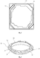
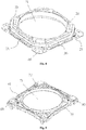
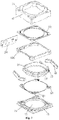
- the lens drive motor includes a housing 10, a lens support 20, a coil 30 and a magnet component 40; the coil 30 is wrapped around the lens support 20 and is provided in the housing 10; the magnet component 40 is provided between the housing 10 and the lens support 20, wherein a portion, corresponding to the magnet component 40, of the housing 10 is made of a first material, and other portions of the housing 10 are made of a second material; and a magnetic conductivity of the second material is smaller than a magnetic conductivity of the first material.
- an electromagnetic induction is generated to drive the lens support 20 to move.
- the portion corresponding to the magnet component 40 is the first material which has better magnetic conductivity, a flux leakage paths may be reduced, the flux leakage is reduced, a relatively strong magnetic field intensity is guaranteed and the motor is guaranteed to have sufficient driving force; a relatively large driving force can be generated under the action of a very small current, and an energy consumption is reduced; in addition, since the magnetic field intensity is effectively improved, a magnetic field component may be designed to be lighter and thinner, and thus a lens drive motor which is lighter and thinner can be designed and an aesthetics is improved; and besides, a compressive strength of the second material is greater than that of the first material, so on a premise of guaranteeing the magnetic field intensity, the compressive strength of the lens drive motor is increased and the very good protective effect is taken on the lens drive motor.
- the first material and the second material are fixed by welding.
- the operation is simple and practical, the implementation is convenient, the connection is firm, the stability and the reliability are high, and the cost is relatively low.
- the first material is an SPCC material; and the second material is an SUS material.
- the SPCC material has good magnetic conductivity, so the flux leakage paths may be reduced, the flux leakage is reduced, the static electricity may be prevented, the very good protective effect is taken on the magnet component 40, the magnetic field intensity between the magnet component 40 and the coil 30 is improved, the driving force of the motor is increased and the cost is relative low.
- the SUS material has relatively high strength, the impact resistance is relatively strong, the stability is good and it can take the very good protective effect to the lens drive motor.
- the materials are placed according to left and right arrangements in a sequence of SPCC material + SUS material + SPCC material and welded, then are processed via a calendaring technique and at last are machined into a required form.
- the SPCC material is adopted, the mutual repulsive force of the motor is greatly reduced, so that the motor is better applied to a double camera.
- a welding groove is well machined and repaired. Therefore, different materials are combined very effectively. Seemingly, the welding groove is also very smooth and it is difficult to distinguish that the welding groove is a combination of the two materials.
- a portion, corresponding to the magnet component 40, of a peripheral wall of the housing 10 is made of the first material.
- the magnetic conductivity of the first material is better than that of the second material and the first material is arranged corresponding to the magnet component 40, so the flux leakage paths may be reduced, the leakage of the magnetic field can be effectively avoided and the relatively strong magnetic field intensity is guaranteed; and thus, the motor is guaranteed to have the sufficient driving force, a relatively large driving force can be generated under the action of a very small current, and the energy consumption is reduced; in addition, since the magnetic field intensity is effectively improved, a magnetic field component may be designed to be lighter and thinner, and thus a lens drive motor which is lighter and thinner can be designed and the aesthetics is improved.
- the magnet component 40 includes multiple sub-magnets provided in pairs; and two sub-magnets of each pair of the multiple sub-magnets are respectively positioned at two sides of the lens support 20 and are at least corresponding to straight edges of the housing 10.
- the lens drive motor further includes upper spring 50 positioned above the lens support 20, and lower spring 60 positioned below the lens support 20; two sub-magnets of each pair are formed into 180° one another and are arranged oppositely.
- an electromagnetic force is generated between the coil 30 and the magnet component 40.
- the lens support 20 is driven to move linearly along an optical axis direction of the lens, and the lens support 20 is finally stayed at a position where the electromagnetic force between the coil 30 and the magnet is in a balanced state with the resultant force of elastic forces of the upper spring 50 and the lower spring 60.
- the lens support 20 can be controlled to move to a target position, thus achieving the focusing purpose.
- each of the multiple sub-magnets is of a bent type structure; each of the multiple sub-magnets includes a main body segment and an extending segment connected sequentially; an included angle is formed between the extending segment and the main body segment; multiple straight edge segments 21 and multiple corner segments 22 connecting the multiple straight edge segments 21 are included at a outer periphery of the lens support 20; the main body segment cover corresponding one straight edge segment of the multiple straight edge segments 21; and the extending segment stretch out to one of the corner segments 22.
- each of the multiple sub-magnets can be cooperated with the coil 30 at the straight edge segments 21 and multiple corner segments 22, the effective action area between the magnet component 40 and the coil 30 is increased, the magnetic field intensity is improved and thus the driving force of the motor is increased.
- the included angle between the extending segment and the main body segment is provided in cooperation with one of included angles between the straight edge segments 21 and the corner segments 22, so that the magnet component 40 and the lens support 20 are protected better.
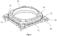
- the multiple straight edge segments 21 and the multiple corner segments 22 connecting the multiple straight edge segments 21 are included at a outer periphery of the lens support 20; at least one of the multiple corner segments 22 is provided with a wrapping post 23; the magnet component 40 is provided in avoidance of the wrapping post 23; and end portions of the coil 30 are fixed on the wrapping post 23.
- the multiple corner segments 22 are four corner segments 22, and there are two wrapping posts 23; and the two wrapping posts 23 are respectively provided on two corner segments 22 symmetrical to each other.
- the lens support 20 is provided with a wire wrapping area; a plurality of limiting ridges 25 for stopping the coil 30 are provided in the wire wrapping area; a plurality of anti-impact ridges are further provided in the wire wrapping area; and the coil 30 is wrapped in the wire wrapping area to cover the anti-impact ridges.
- the limiting ridges 25 is provided, a very good limiting and protecting effect can be taken on the coil 30.
- the anti-impact ridge 26 the impact resistance between the wrapped coil 30 and the lens support 20 will be greatly enhanced; and therefore, even under the action of an external force, the coil 30 also will not be dropped from the lens support 20 and thus the reliability of the lens drive motor is improved.
- a thickness H1 of a corner portion 11 of a peripheral wall of the housing 10 is greater than a thickness H2 of other portions of the peripheral wall of the housing 10.
- a ratio of the thickness H2 to the thickness H1 is greater than 0.6 and is less than 1.
- the thickness H1 is greater than or equal to 0.2mm and is smaller than or equal to 0.25mm. In this way, the better protective effect can be taken on the magnet component 40, the leakage of the magnetic field can be effectively avoided and the relatively strong magnetic field intensity is guaranteed; and thus, the motor is guaranteed to have the sufficient driving force and a relatively large driving force can be generated under the action of a very small current, thereby reducing the energy consumption.
- the thickness H1 of the corner portion of the peripheral wall of the housing 10 may further be improved. Increasing the thickness H1 is the most direct and obvious to enhance the flux leakage resistance of the motor and further accelerate the push effect of the motor. And meanwhile, the design requirement on lighting and thinning also can be met.
- the thickness H1 is equal to 0.2mm. In such a manner, the housing 10 can be guaranteed to take the best protective effect on the magnet component 40, the flux leakage resistance is the best and the magnetic field intensity is the best.
- the thickness H2 is greater than or equal to 0.15mm and is smaller than or equal to 0.2mm. In this way, on the premise of meeting the use requirements, the thickness and the weight of the housing 10 are guaranteed to be in a relatively small range, the size of the housing 10 is reduced and thus the lens drive motor is relatively light and thin.
- the thickness H2 it is relatively difficult to change or increase the thickness H2 within a given compact and limited space range of the motor, and the involved influence range is relatively large.
- the sizes of all relevant components inside the housing 10 will be correspondingly adjusted and changed and the cost for such change is relatively high. Since the sizes of the coil 30 and the magnet component 40 are shrunken and are changed, the comprehensive result is unnecessarily in favor of improving the overall performance including the thrust performance of the motor and implementing standardization of motor products.
- the most reasonable and feasible way is to keep the thickness H2 unchanged and increase the thickness H1.
- the present embodiment is a technical improvement made for the purpose of improving the functions of the motor, and the thrust performance will be greatly improved compared with that ever before.
- the thickness H2 is equal to 0.15mm. In this way, on the premise of meeting the use requirement, the thickness and the weight of the housing 10 can be guaranteed to be in an optimal range and the size of the housing 10 is reduced; and thus, the lighting and thinning degrees of the lens drive motor are optimal and the aesthetics is improved.
- the thicker the housing 10 corresponding to the magnet component 40 the less magnetic force lines, and thus the adverse condition of the flux leakage can be more effectively prohibited. That is, under the condition of a same current, the higher the magnetic field intensity generated by the magnet component 40, the more obvious on improvement of the driving force of the motor.
- a lens with a relatively large weight can be carried and driven, a high-pixel lens drive motor is provided and the structural design on low current and miniaturization of the lens drive motor is implemented.
- the selected thickness is 0.2mm
- a thickness H1 of the portion, corresponding to the magnet component 40, on the peripheral wall of the housing 10 is changed into 0.2mm or more and the thickness of the housing 10 on other portions is machined into 0.15mm; the specific implementation manner is as follows: a 0.2mm material strap is extruded via a mould by the housing 10 manufacturer into the thicknesses such as 0.15mm. Therefore, compared with the former driving force, 25% driving force may be improved.
- the lens drive motor further includes upper springs 50 positioned above the lens support 20, and lower spring 60 positioned below the lens support 20; and a plurality of glue holes are formed at a plurality of vortex angles of the upper spring 50.
- the upper spring 50 is configured to support an upper end surface of the lens support 20 and the lower spring 60 is configured to support a lower end surface of the lens support 20. Since the glue holes are formed at a plurality of vortex angles of the upper spring 50, the upper spring 50 and the lens support 20 can be fixedly connected via a manner of injecting a glue to improve the anti-impact capacity of the lens drive motor and improve the stability. Moreover, by injecting the glue into the glue holes, the spillover can be prevented from affecting the performance of other structures.
- the lens drive motor further includes a pedestal 70; the housing 10 is arranged on the pedestal 70 to form a accommodating therebetween; the lens support 20, the coil 30 and the magnet component 40 all are positioned in the accommodating; and the housing 10 and the pedestal 70 are assembled together via an embedment structure.
- the pedestal 70 is configured to support the lens support 20, the coil 30 and the magnet component 40, and under the joint action of the pedestal 70 and the housing 10, provides the accommodating for the lens support 20, the coil 30 and the magnet component 40; furthermore, it can take the effect of protecting internal components.
- the housing 10 and the pedestal 70 are assembled together via the embedment structure, so the structure is simple, the operation is convenient, the assembly effect is good and the reliability and the stability are strong.
- the pedestal 70 is provided with a central avoidance opening 71 and a dustproof ring 72; and the dustproof ring 72 extends along the circumferential direction of the central avoidance opening 71.
- the lens support 20 is provided with a holding cavity.
- the dustproof ring 72 stretches into the holding cavity of the lens support 20 and is combined with the holding cavity in a noncontact staggered manner, so that very good dustproof effect can be taken.
- the embedment structure includes a plurality of gap portions and a plurality of projection portions 82; the gap portions are arranged on the housing 10; and the projection portions 82 are arranged at a outer periphery of the pedestal 70 and can be embedded into the gap portions.
- the projection portions 82 and the gap portions 81 both are simply structured, can meet the requirement on the embedment and have good assembly effect and strong reliability and stability.
- the gap portions are positioned at the vortex angles of the housing 10. In this way, the adverse effect to other components may be avoided, and the use performance of the lens drive motor is improved.
- multiple positioning posts are provided on a lower end surface of the lens support 20; the lower spring 60 is provided with multiple positioning holes 61; and the multiple positioning posts are cooperatively arranged with the multiple positioning holes 61.
- the lens support 20 and the lower spring 60 are cooperatively connected via the positioning posts and the positioning holes 61, so that the reliability of the assembly is increased and simultaneously the convenience in assembly may be improved.
- the configuration number of the sub-magnets in the bent type structure may be adjusted to achieve the optimal driving effect.
- the compactness of the lens drive motor can be increased and the size of the lens drive motor is reduced; and when a gap is provided between the magnet component 40 and the housing 10, the glue is conveniently injected into the gap for adhering and fixing and thus the adhesiveness between the magnet component 40 and the housing 10 can be increased.
- the present embodiment is a closed-loop motor.
- a current position where the lens is located can be calculated and detected.
- the quick and accurate focusing purpose may be achieved.
- the above is implemented by a position feedback system of the closed-loop motor, which is the function distinguished from the conventional motor.
- the sides of the housing 10 are made of the SPCC material, which is intended to effectively reduce the flux leakage phenomenon of the magnet component 40 and increase the magnetic field intensity with the coil 30, thus improving the thrust of the motor. Therefore, the housing 10 is made using a combined manner of the SPCC material and the SUS material, so that the performance of the motor may be enhanced and a problem of poor stroke of the motor due to insufficient thrust of the motor can be improved.
- the whole housing of the closed-loop motor is made of the SUS material.
- the material SUS of which the sides of the housing 10 are made generally is replaced into the SPCC material to obtain the optimal driving force.
- the housing 10 in the combined form of the SPCC material and the SUS material not only is applied to the application of the closed-loop motor, but also may be applied to an OIS type of motor or other types of VCM motors.
Landscapes
- Physics & Mathematics (AREA)
- Engineering & Computer Science (AREA)
- General Physics & Mathematics (AREA)
- Power Engineering (AREA)
- Optics & Photonics (AREA)
- Chemical & Material Sciences (AREA)
- Combustion & Propulsion (AREA)
- Electromagnetism (AREA)
- Microelectronics & Electronic Packaging (AREA)
- Lens Barrels (AREA)
Claims (9)
- Moteur d'entraînement d'objectif, dans lequel le moteur d'entraînement d'objectif comprend : un boîtier (10), un support d'objectif (20), une bobine (30) et un composant d'aimant (40), la bobine (30) étant enroulée autour du support d'objectif (20) et étant prévue dans le boîtier (10), le composant d'aimant (40) étant prévu entre le boîtier (10) et le support d'objectif (20), dans lequel le composant d'aimant (40) comprend de multiples sous-aimants prévus par paires ; et deux sous-aimants de chaque paire des multiples sous-aimants sont positionnés respectivement au niveau de deux côtés du support d'objectif (20) et correspondent au moins à des bords droits du boîtier (10),chacun des multiples sous-aimants est de structure de type coudé ;chacun des multiples sous-aimants comprend un segment de corps principal et un segment d'extension reliés séquentiellement ; un angle inclus est formé entre le segment d'extension et le segment de corps principal ;de multiples segments de bord droit (21) et de multiples segments de coin (22) reliant les multiples segments de bord droit (21) sont compris au niveau d'une périphérie externe du support d'objectif (20) ; le segment de corps principal couvre un segment de bord droit correspondant des multiples segments de bord droit (21) ; et le segment d'extension s'allonge vers l'un des segments de coin (22),caractérisé en ce qu'une portion, correspondant au composant d'aimant (40), d'une paroi périphérique du boîtier (10) est constituée d'un premier matériau, et d'autres portions du boîtier (10) sont constituées d'un second matériau ; et une conductivité magnétique du second matériau est inférieure à une conductivité magnétique du premier matériau, une épaisseur H1 d'une portion de coin (11) d'une paroi périphérique du boîtier (10) est supérieure à une épaisseur H2 d'autres portions de la paroi périphérique du boîtier (10), le premier matériau et le second matériau sont fixés par soudage, le premier matériau est un matériau en acier SPCC, le second matériau est un acier inoxydable de type SUS.
- Moteur d'entraînement d'objectif selon la revendication 1, dans lequel de multiples segments de bord droit (21) et de multiples segments de coin (22) reliant les multiples segments de bord droit (21) sont compris au niveau d'une périphérie externe du support d'objectif (20) ; au moins l'un des multiples segments de coin (22) est pourvu d'un tenon d'enroulement (23) ; le composant d'aimant (40) est prévu pour éviter le tenon d'enroulement (23) ; et des portions d'extrémité de la bobine (30) sont fixées sur le tenon d'enroulement (23).
- Moteur d'entraînement d'objectif selon la revendication 2, dans lequel les multiples segments de coin (22) sont quatre segments de coin (22), et il y a deux tenons d'enroulement (23) ; et les deux tenons d'enroulement (23) sont prévus respectivement sur deux segments de coin (22) symétriques l'un à l'autre.
- Moteur d'entraînement d'objectif selon la revendication 1, dans lequel le support d'objectif est pourvu d'une zone d'enroulement de câble ; une pluralité de crêtes de limitation (25) pour arrêter la bobine (30) sont prévues dans la zone d'enroulement de câble ; une pluralité de crêtes anti-impact (30) sont en outre prévues dans la zone d'enroulement de câble ; et la bobine (30) est enroulée dans la zone d'enroulement de câble pour couvrir les crêtes anti-impact.
- Moteur d'entraînement d'objectif selon la revendication 1, dans lequel un rapport entre l'épaisseur H2 et l'épaisseur H1 est supérieur à 0,6 et est inférieur à 1.
- Moteur d'entraînement d'objectif selon la revendication 1, dans lequel l'épaisseur H1 est supérieure ou égale à 0,2 mm et est inférieure ou égale à 0,25 mm ;en outre, l'épaisseur H1 est égale à 0,2 mm ;l'épaisseur H2 est supérieure ou égale à 0,15 mm et est inférieure ou égale à 0,2 mm ;en outre, l'épaisseur H1 est égale à 0,15 mm.
- Caméra, dans laquelle la caméra comprend le moteur d'entraînement d'objectif tel que revendiqué à l'une quelconque des revendications 1 à 6.
- Appareil terminal mobile, dans lequel l'appareil terminal mobile comprend la caméra telle que revendiquée à la revendication 7.
- Appareil terminal mobile selon la revendication 8, dans lequel l'appareil terminal mobile comprend au moins l'un parmi un téléphone mobile, un terminal porteur d'informations et un ordinateur portatif.
Applications Claiming Priority (1)
| Application Number | Priority Date | Filing Date | Title |
|---|---|---|---|
| CN201810726083.0A CN108710189B (zh) | 2018-07-04 | 2018-07-04 | 透镜驱动马达、相机及移动终端装置 |
Publications (2)
| Publication Number | Publication Date |
|---|---|
| EP3591817A1 EP3591817A1 (fr) | 2020-01-08 |
| EP3591817B1 true EP3591817B1 (fr) | 2021-12-29 |
Family
ID=63873796
Family Applications (1)
| Application Number | Title | Priority Date | Filing Date |
|---|---|---|---|
| EP18204406.5A Active EP3591817B1 (fr) | 2018-07-04 | 2018-11-05 | Moteur d'entraînement d'objectif, caméra et appareil terminal mobile |
Country Status (4)
| Country | Link |
|---|---|
| US (1) | US11016263B2 (fr) |
| EP (1) | EP3591817B1 (fr) |
| CN (1) | CN108710189B (fr) |
| ES (1) | ES2909379T3 (fr) |
Families Citing this family (6)
| Publication number | Priority date | Publication date | Assignee | Title |
|---|---|---|---|---|
| CN109375334A (zh) * | 2018-12-24 | 2019-02-22 | 上海比路电子股份有限公司 | 透镜驱动装置、防抖系统以及摄像装置 |
| CN109597182A (zh) * | 2018-12-27 | 2019-04-09 | 上海比路电子股份有限公司 | 透镜驱动马达、相机及移动终端装置 |
| KR102799219B1 (ko) * | 2019-03-13 | 2025-04-23 | 엘지이노텍 주식회사 | 렌즈 구동 장치 및 카메라 모듈 |
| CN111722350B (zh) * | 2019-03-20 | 2025-06-13 | 新思考电机有限公司 | 驱动装置壳体、驱动装置、照相装置及电子设备 |
| US11835683B2 (en) * | 2020-12-18 | 2023-12-05 | Tdk Taiwan Corp. | Tactile feedback mechanism |
| CN114665639A (zh) * | 2022-03-02 | 2022-06-24 | 河源友华微机电科技有限公司 | 一种透镜驱动马达、相机及移动终端装置 |
Family Cites Families (13)
| Publication number | Priority date | Publication date | Assignee | Title |
|---|---|---|---|---|
| US3465361A (en) * | 1965-01-13 | 1969-09-02 | Rosemount Eng Co Ltd | Electromagnetic wave retarding structure |
| JP2000357331A (ja) * | 1999-06-14 | 2000-12-26 | Hitachi Ltd | 対物レンズ駆動装置 |
| JP4672315B2 (ja) * | 2004-09-06 | 2011-04-20 | 東芝機械株式会社 | リニアモータおよびリニア移動ステージ装置 |
| KR100649638B1 (ko) | 2005-04-18 | 2006-11-27 | 삼성전기주식회사 | 조립성이 향상된 렌즈 이송장치 |
| GB0702897D0 (en) * | 2007-02-15 | 2007-03-28 | Johnson Electric Sa | Voice coil motor |
| KR101093738B1 (ko) | 2011-05-04 | 2011-12-19 | (주)차바이오앤디오스텍 | 소형화 및 경량화가 가능한 렌즈 구동 장치 |
| JP2013068702A (ja) * | 2011-09-21 | 2013-04-18 | Shicoh Engineering Co Ltd | レンズ駆動装置、オートフォーカスカメラ及びカメラ付きモバイル端末 |
| KR102178923B1 (ko) * | 2014-01-03 | 2020-11-13 | 엘지이노텍 주식회사 | 카메라 모듈 |
| US20150312452A1 (en) * | 2014-04-24 | 2015-10-29 | Apple Inc. | Clamping clip for camera module focusing during assembly |
| CN105511048A (zh) * | 2015-12-29 | 2016-04-20 | 上海比路电子有限公司 | 一种光学防抖驱动器 |
| CN106646810B (zh) * | 2016-11-11 | 2024-01-19 | 上海比路电子股份有限公司 | 一种透镜驱动装置 |
| CN207318817U (zh) * | 2017-10-03 | 2018-05-04 | 惠州大亚湾三美达光学技术有限公司 | 一种透镜驱动装置 |
| CN208367302U (zh) * | 2018-07-04 | 2019-01-11 | 上海比路电子股份有限公司 | 透镜驱动马达、相机及移动终端装置 |
-
2018
- 2018-07-04 CN CN201810726083.0A patent/CN108710189B/zh active Active
- 2018-11-05 EP EP18204406.5A patent/EP3591817B1/fr active Active
- 2018-11-05 US US16/180,035 patent/US11016263B2/en active Active
- 2018-11-05 ES ES18204406T patent/ES2909379T3/es active Active
Non-Patent Citations (1)
| Title |
|---|
| None * |
Also Published As
| Publication number | Publication date |
|---|---|
| US11016263B2 (en) | 2021-05-25 |
| EP3591817A1 (fr) | 2020-01-08 |
| CN108710189B (zh) | 2024-08-16 |
| CN108710189A (zh) | 2018-10-26 |
| US20200012070A1 (en) | 2020-01-09 |
| ES2909379T3 (es) | 2022-05-06 |
Similar Documents
| Publication | Publication Date | Title |
|---|---|---|
| EP3591817B1 (fr) | Moteur d'entraînement d'objectif, caméra et appareil terminal mobile | |
| JP7581425B2 (ja) | レンズ駆動モータ | |
| EP3591452B1 (fr) | Moteur d'entraînement d'objectif, caméra et appareil terminal mobile | |
| US11874520B2 (en) | Optical element driving module | |
| US20230305265A1 (en) | Lens driving device, camera module and optical apparatus | |
| US9977254B2 (en) | Camera lens module | |
| US20210018719A1 (en) | Lens assembly | |
| EP3567847A1 (fr) | Dispositif d'entraînement à double lentille, module de caméra double et dispositif optique | |
| US11622173B2 (en) | Lens driving device | |
| KR102586187B1 (ko) | 렌즈구동장치 및 이를 포함하는 카메라장치 | |
| US11561410B2 (en) | Driving mechanism for optical element | |
| US20240302714A1 (en) | Aperture Adjusting Apparatus, Camera Module, and Mobile Terminal | |
| KR102151246B1 (ko) | 렌즈 구동 액추에이터 | |
| KR102220729B1 (ko) | 렌즈구동모터 | |
| KR20230104567A (ko) | 카메라 모듈 및 광학기기 | |
| US20120148222A1 (en) | Voice coil motor, camera module and portable electronic device having same | |
| CN108681025A (zh) | 透镜驱动马达、相机及移动终端装置 | |
| US10763735B2 (en) | Voice coil motor and electronic device having the same | |
| CN108681027A (zh) | 透镜驱动马达、相机及移动终端装置 | |
| KR20240148772A (ko) | 렌즈구동모터 | |
| CN208367302U (zh) | 透镜驱动马达、相机及移动终端装置 | |
| KR20220130066A (ko) | 렌즈 구동 유닛, 카메라 모듈 및 광학기기 | |
| CN120528205A (zh) | 磁驱动装置、摄像模组及电子设备 | |
| CN121008374A (zh) | 棱镜驱动马达、摄像装置及电子设备 | |
| KR20230014814A (ko) | 카메라 모듈 및 광학기기 |
Legal Events
| Date | Code | Title | Description |
|---|---|---|---|
| PUAI | Public reference made under article 153(3) epc to a published international application that has entered the european phase |
Free format text: ORIGINAL CODE: 0009012 |
|
| STAA | Information on the status of an ep patent application or granted ep patent |
Free format text: STATUS: THE APPLICATION HAS BEEN PUBLISHED |
|
| AK | Designated contracting states |
Kind code of ref document: A1 Designated state(s): AL AT BE BG CH CY CZ DE DK EE ES FI FR GB GR HR HU IE IS IT LI LT LU LV MC MK MT NL NO PL PT RO RS SE SI SK SM TR |
|
| AX | Request for extension of the european patent |
Extension state: BA ME |
|
| STAA | Information on the status of an ep patent application or granted ep patent |
Free format text: STATUS: REQUEST FOR EXAMINATION WAS MADE |
|
| 17P | Request for examination filed |
Effective date: 20200702 |
|
| RBV | Designated contracting states (corrected) |
Designated state(s): AL AT BE BG CH CY CZ DE DK EE ES FI FR GB GR HR HU IE IS IT LI LT LU LV MC MK MT NL NO PL PT RO RS SE SI SK SM TR |
|
| STAA | Information on the status of an ep patent application or granted ep patent |
Free format text: STATUS: EXAMINATION IS IN PROGRESS |
|
| 17Q | First examination report despatched |
Effective date: 20201013 |
|
| GRAP | Despatch of communication of intention to grant a patent |
Free format text: ORIGINAL CODE: EPIDOSNIGR1 |
|
| STAA | Information on the status of an ep patent application or granted ep patent |
Free format text: STATUS: GRANT OF PATENT IS INTENDED |
|
| INTG | Intention to grant announced |
Effective date: 20210629 |
|
| GRAS | Grant fee paid |
Free format text: ORIGINAL CODE: EPIDOSNIGR3 |
|
| GRAA | (expected) grant |
Free format text: ORIGINAL CODE: 0009210 |
|
| STAA | Information on the status of an ep patent application or granted ep patent |
Free format text: STATUS: THE PATENT HAS BEEN GRANTED |
|
| AK | Designated contracting states |
Kind code of ref document: B1 Designated state(s): AL AT BE BG CH CY CZ DE DK EE ES FI FR GB GR HR HU IE IS IT LI LT LU LV MC MK MT NL NO PL PT RO RS SE SI SK SM TR |
|
| REG | Reference to a national code |
Ref country code: GB Ref legal event code: FG4D |
|
| REG | Reference to a national code |
Ref country code: CH Ref legal event code: EP |
|
| REG | Reference to a national code |
Ref country code: DE Ref legal event code: R096 Ref document number: 602018028732 Country of ref document: DE |
|
| REG | Reference to a national code |
Ref country code: AT Ref legal event code: REF Ref document number: 1459420 Country of ref document: AT Kind code of ref document: T Effective date: 20220115 |
|
| REG | Reference to a national code |
Ref country code: IE Ref legal event code: FG4D |
|
| REG | Reference to a national code |
Ref country code: LT Ref legal event code: MG9D |
|
| PG25 | Lapsed in a contracting state [announced via postgrant information from national office to epo] |
Ref country code: RS Free format text: LAPSE BECAUSE OF FAILURE TO SUBMIT A TRANSLATION OF THE DESCRIPTION OR TO PAY THE FEE WITHIN THE PRESCRIBED TIME-LIMIT Effective date: 20211229 Ref country code: LT Free format text: LAPSE BECAUSE OF FAILURE TO SUBMIT A TRANSLATION OF THE DESCRIPTION OR TO PAY THE FEE WITHIN THE PRESCRIBED TIME-LIMIT Effective date: 20211229 Ref country code: FI Free format text: LAPSE BECAUSE OF FAILURE TO SUBMIT A TRANSLATION OF THE DESCRIPTION OR TO PAY THE FEE WITHIN THE PRESCRIBED TIME-LIMIT Effective date: 20211229 Ref country code: BG Free format text: LAPSE BECAUSE OF FAILURE TO SUBMIT A TRANSLATION OF THE DESCRIPTION OR TO PAY THE FEE WITHIN THE PRESCRIBED TIME-LIMIT Effective date: 20220329 |
|
| REG | Reference to a national code |
Ref country code: NL Ref legal event code: MP Effective date: 20211229 |
|
| REG | Reference to a national code |
Ref country code: ES Ref legal event code: FG2A Ref document number: 2909379 Country of ref document: ES Kind code of ref document: T3 Effective date: 20220506 |
|
| REG | Reference to a national code |
Ref country code: AT Ref legal event code: MK05 Ref document number: 1459420 Country of ref document: AT Kind code of ref document: T Effective date: 20211229 |
|
| PG25 | Lapsed in a contracting state [announced via postgrant information from national office to epo] |
Ref country code: SE Free format text: LAPSE BECAUSE OF FAILURE TO SUBMIT A TRANSLATION OF THE DESCRIPTION OR TO PAY THE FEE WITHIN THE PRESCRIBED TIME-LIMIT Effective date: 20211229 Ref country code: NO Free format text: LAPSE BECAUSE OF FAILURE TO SUBMIT A TRANSLATION OF THE DESCRIPTION OR TO PAY THE FEE WITHIN THE PRESCRIBED TIME-LIMIT Effective date: 20220329 Ref country code: LV Free format text: LAPSE BECAUSE OF FAILURE TO SUBMIT A TRANSLATION OF THE DESCRIPTION OR TO PAY THE FEE WITHIN THE PRESCRIBED TIME-LIMIT Effective date: 20211229 Ref country code: HR Free format text: LAPSE BECAUSE OF FAILURE TO SUBMIT A TRANSLATION OF THE DESCRIPTION OR TO PAY THE FEE WITHIN THE PRESCRIBED TIME-LIMIT Effective date: 20211229 Ref country code: GR Free format text: LAPSE BECAUSE OF FAILURE TO SUBMIT A TRANSLATION OF THE DESCRIPTION OR TO PAY THE FEE WITHIN THE PRESCRIBED TIME-LIMIT Effective date: 20220330 |
|
| PG25 | Lapsed in a contracting state [announced via postgrant information from national office to epo] |
Ref country code: NL Free format text: LAPSE BECAUSE OF FAILURE TO SUBMIT A TRANSLATION OF THE DESCRIPTION OR TO PAY THE FEE WITHIN THE PRESCRIBED TIME-LIMIT Effective date: 20211229 |
|
| PG25 | Lapsed in a contracting state [announced via postgrant information from national office to epo] |
Ref country code: SM Free format text: LAPSE BECAUSE OF FAILURE TO SUBMIT A TRANSLATION OF THE DESCRIPTION OR TO PAY THE FEE WITHIN THE PRESCRIBED TIME-LIMIT Effective date: 20211229 Ref country code: SK Free format text: LAPSE BECAUSE OF FAILURE TO SUBMIT A TRANSLATION OF THE DESCRIPTION OR TO PAY THE FEE WITHIN THE PRESCRIBED TIME-LIMIT Effective date: 20211229 Ref country code: RO Free format text: LAPSE BECAUSE OF FAILURE TO SUBMIT A TRANSLATION OF THE DESCRIPTION OR TO PAY THE FEE WITHIN THE PRESCRIBED TIME-LIMIT Effective date: 20211229 Ref country code: PT Free format text: LAPSE BECAUSE OF FAILURE TO SUBMIT A TRANSLATION OF THE DESCRIPTION OR TO PAY THE FEE WITHIN THE PRESCRIBED TIME-LIMIT Effective date: 20220429 Ref country code: EE Free format text: LAPSE BECAUSE OF FAILURE TO SUBMIT A TRANSLATION OF THE DESCRIPTION OR TO PAY THE FEE WITHIN THE PRESCRIBED TIME-LIMIT Effective date: 20211229 Ref country code: CZ Free format text: LAPSE BECAUSE OF FAILURE TO SUBMIT A TRANSLATION OF THE DESCRIPTION OR TO PAY THE FEE WITHIN THE PRESCRIBED TIME-LIMIT Effective date: 20211229 |
|
| PG25 | Lapsed in a contracting state [announced via postgrant information from national office to epo] |
Ref country code: PL Free format text: LAPSE BECAUSE OF FAILURE TO SUBMIT A TRANSLATION OF THE DESCRIPTION OR TO PAY THE FEE WITHIN THE PRESCRIBED TIME-LIMIT Effective date: 20211229 Ref country code: AT Free format text: LAPSE BECAUSE OF FAILURE TO SUBMIT A TRANSLATION OF THE DESCRIPTION OR TO PAY THE FEE WITHIN THE PRESCRIBED TIME-LIMIT Effective date: 20211229 |
|
| PG25 | Lapsed in a contracting state [announced via postgrant information from national office to epo] |
Ref country code: IS Free format text: LAPSE BECAUSE OF FAILURE TO SUBMIT A TRANSLATION OF THE DESCRIPTION OR TO PAY THE FEE WITHIN THE PRESCRIBED TIME-LIMIT Effective date: 20220429 |
|
| REG | Reference to a national code |
Ref country code: DE Ref legal event code: R097 Ref document number: 602018028732 Country of ref document: DE |
|
| PG25 | Lapsed in a contracting state [announced via postgrant information from national office to epo] |
Ref country code: DK Free format text: LAPSE BECAUSE OF FAILURE TO SUBMIT A TRANSLATION OF THE DESCRIPTION OR TO PAY THE FEE WITHIN THE PRESCRIBED TIME-LIMIT Effective date: 20211229 Ref country code: AL Free format text: LAPSE BECAUSE OF FAILURE TO SUBMIT A TRANSLATION OF THE DESCRIPTION OR TO PAY THE FEE WITHIN THE PRESCRIBED TIME-LIMIT Effective date: 20211229 |
|
| PLBE | No opposition filed within time limit |
Free format text: ORIGINAL CODE: 0009261 |
|
| STAA | Information on the status of an ep patent application or granted ep patent |
Free format text: STATUS: NO OPPOSITION FILED WITHIN TIME LIMIT |
|
| 26N | No opposition filed |
Effective date: 20220930 |
|
| PG25 | Lapsed in a contracting state [announced via postgrant information from national office to epo] |
Ref country code: SI Free format text: LAPSE BECAUSE OF FAILURE TO SUBMIT A TRANSLATION OF THE DESCRIPTION OR TO PAY THE FEE WITHIN THE PRESCRIBED TIME-LIMIT Effective date: 20211229 |
|
| PG25 | Lapsed in a contracting state [announced via postgrant information from national office to epo] |
Ref country code: MC Free format text: LAPSE BECAUSE OF FAILURE TO SUBMIT A TRANSLATION OF THE DESCRIPTION OR TO PAY THE FEE WITHIN THE PRESCRIBED TIME-LIMIT Effective date: 20211229 |
|
| REG | Reference to a national code |
Ref country code: CH Ref legal event code: PL |
|
| REG | Reference to a national code |
Ref country code: BE Ref legal event code: MM Effective date: 20221130 |
|
| PG25 | Lapsed in a contracting state [announced via postgrant information from national office to epo] |
Ref country code: LI Free format text: LAPSE BECAUSE OF NON-PAYMENT OF DUE FEES Effective date: 20221130 Ref country code: CH Free format text: LAPSE BECAUSE OF NON-PAYMENT OF DUE FEES Effective date: 20221130 |
|
| PG25 | Lapsed in a contracting state [announced via postgrant information from national office to epo] |
Ref country code: LU Free format text: LAPSE BECAUSE OF NON-PAYMENT OF DUE FEES Effective date: 20221105 |
|
| PG25 | Lapsed in a contracting state [announced via postgrant information from national office to epo] |
Ref country code: IE Free format text: LAPSE BECAUSE OF NON-PAYMENT OF DUE FEES Effective date: 20221105 |
|
| PG25 | Lapsed in a contracting state [announced via postgrant information from national office to epo] |
Ref country code: BE Free format text: LAPSE BECAUSE OF NON-PAYMENT OF DUE FEES Effective date: 20221130 |
|
| PG25 | Lapsed in a contracting state [announced via postgrant information from national office to epo] |
Ref country code: HU Free format text: LAPSE BECAUSE OF FAILURE TO SUBMIT A TRANSLATION OF THE DESCRIPTION OR TO PAY THE FEE WITHIN THE PRESCRIBED TIME-LIMIT; INVALID AB INITIO Effective date: 20181105 |
|
| PG25 | Lapsed in a contracting state [announced via postgrant information from national office to epo] |
Ref country code: CY Free format text: LAPSE BECAUSE OF FAILURE TO SUBMIT A TRANSLATION OF THE DESCRIPTION OR TO PAY THE FEE WITHIN THE PRESCRIBED TIME-LIMIT Effective date: 20211229 |
|
| PG25 | Lapsed in a contracting state [announced via postgrant information from national office to epo] |
Ref country code: MK Free format text: LAPSE BECAUSE OF FAILURE TO SUBMIT A TRANSLATION OF THE DESCRIPTION OR TO PAY THE FEE WITHIN THE PRESCRIBED TIME-LIMIT Effective date: 20211229 |
|
| PG25 | Lapsed in a contracting state [announced via postgrant information from national office to epo] |
Ref country code: MT Free format text: LAPSE BECAUSE OF FAILURE TO SUBMIT A TRANSLATION OF THE DESCRIPTION OR TO PAY THE FEE WITHIN THE PRESCRIBED TIME-LIMIT Effective date: 20211229 |
|
| PG25 | Lapsed in a contracting state [announced via postgrant information from national office to epo] |
Ref country code: TR Free format text: LAPSE BECAUSE OF FAILURE TO SUBMIT A TRANSLATION OF THE DESCRIPTION OR TO PAY THE FEE WITHIN THE PRESCRIBED TIME-LIMIT Effective date: 20211229 |
|
| PGFP | Annual fee paid to national office [announced via postgrant information from national office to epo] |
Ref country code: GB Payment date: 20251126 Year of fee payment: 8 |
|
| PGFP | Annual fee paid to national office [announced via postgrant information from national office to epo] |
Ref country code: IT Payment date: 20251126 Year of fee payment: 8 |
|
| PGFP | Annual fee paid to national office [announced via postgrant information from national office to epo] |
Ref country code: FR Payment date: 20251127 Year of fee payment: 8 |
|
| PGFP | Annual fee paid to national office [announced via postgrant information from national office to epo] |
Ref country code: ES Payment date: 20260203 Year of fee payment: 8 |
|
| PGFP | Annual fee paid to national office [announced via postgrant information from national office to epo] |
Ref country code: DE Payment date: 20251224 Year of fee payment: 8 |