EP3592043B1 - Verfahren und vorrichtung zur konfiguration von leistungsverbrauchsparametern - Google Patents
Verfahren und vorrichtung zur konfiguration von leistungsverbrauchsparametern Download PDFInfo
- Publication number
- EP3592043B1 EP3592043B1 EP17902441.9A EP17902441A EP3592043B1 EP 3592043 B1 EP3592043 B1 EP 3592043B1 EP 17902441 A EP17902441 A EP 17902441A EP 3592043 B1 EP3592043 B1 EP 3592043B1
- Authority
- EP
- European Patent Office
- Prior art keywords
- power consumption
- terminal device
- consumption parameter
- relay device
- configured value
- Prior art date
- Legal status (The legal status is an assumption and is not a legal conclusion. Google has not performed a legal analysis and makes no representation as to the accuracy of the status listed.)
- Active
Links
Images


Classifications
-
- H—ELECTRICITY
- H04—ELECTRIC COMMUNICATION TECHNIQUE
- H04W—WIRELESS COMMUNICATION NETWORKS
- H04W88/00—Devices specially adapted for wireless communication networks, e.g. terminals, base stations or access point devices
- H04W88/02—Terminal devices
- H04W88/04—Terminal devices adapted for relaying to or from another terminal or user
-
- H—ELECTRICITY
- H04—ELECTRIC COMMUNICATION TECHNIQUE
- H04W—WIRELESS COMMUNICATION NETWORKS
- H04W52/00—Power management, e.g. Transmission Power Control [TPC] or power classes
- H04W52/02—Power saving arrangements
- H04W52/0209—Power saving arrangements in terminal devices
- H04W52/0212—Power saving arrangements in terminal devices managed by the network, e.g. network or access point is leader and terminal is follower
- H04W52/0216—Power saving arrangements in terminal devices managed by the network, e.g. network or access point is leader and terminal is follower using a pre-established activity schedule, e.g. traffic indication frame
-
- H—ELECTRICITY
- H04—ELECTRIC COMMUNICATION TECHNIQUE
- H04W—WIRELESS COMMUNICATION NETWORKS
- H04W52/00—Power management, e.g. Transmission Power Control [TPC] or power classes
- H04W52/02—Power saving arrangements
- H04W52/0209—Power saving arrangements in terminal devices
- H04W52/0225—Power saving arrangements in terminal devices using monitoring of external events, e.g. the presence of a signal
- H04W52/0229—Power saving arrangements in terminal devices using monitoring of external events, e.g. the presence of a signal where the received signal is a wanted signal
-
- H—ELECTRICITY
- H04—ELECTRIC COMMUNICATION TECHNIQUE
- H04W—WIRELESS COMMUNICATION NETWORKS
- H04W52/00—Power management, e.g. Transmission Power Control [TPC] or power classes
- H04W52/02—Power saving arrangements
- H04W52/0209—Power saving arrangements in terminal devices
- H04W52/0225—Power saving arrangements in terminal devices using monitoring of external events, e.g. the presence of a signal
- H04W52/0229—Power saving arrangements in terminal devices using monitoring of external events, e.g. the presence of a signal where the received signal is a wanted signal
- H04W52/0235—Power saving arrangements in terminal devices using monitoring of external events, e.g. the presence of a signal where the received signal is a wanted signal where the received signal is a power saving command
-
- H—ELECTRICITY
- H04—ELECTRIC COMMUNICATION TECHNIQUE
- H04W—WIRELESS COMMUNICATION NETWORKS
- H04W52/00—Power management, e.g. Transmission Power Control [TPC] or power classes
- H04W52/02—Power saving arrangements
- H04W52/0209—Power saving arrangements in terminal devices
- H04W52/0261—Power saving arrangements in terminal devices managing power supply demand, e.g. depending on battery level
- H04W52/0274—Power saving arrangements in terminal devices managing power supply demand, e.g. depending on battery level by switching on or off the equipment or parts thereof
- H04W52/028—Power saving arrangements in terminal devices managing power supply demand, e.g. depending on battery level by switching on or off the equipment or parts thereof switching on or off only a part of the equipment circuit blocks
-
- H—ELECTRICITY
- H04—ELECTRIC COMMUNICATION TECHNIQUE
- H04W—WIRELESS COMMUNICATION NETWORKS
- H04W76/00—Connection management
- H04W76/20—Manipulation of established connections
- H04W76/28—Discontinuous transmission [DTX]; Discontinuous reception [DRX]
-
- H—ELECTRICITY
- H04—ELECTRIC COMMUNICATION TECHNIQUE
- H04W—WIRELESS COMMUNICATION NETWORKS
- H04W76/00—Connection management
- H04W76/30—Connection release
-
- Y—GENERAL TAGGING OF NEW TECHNOLOGICAL DEVELOPMENTS; GENERAL TAGGING OF CROSS-SECTIONAL TECHNOLOGIES SPANNING OVER SEVERAL SECTIONS OF THE IPC; TECHNICAL SUBJECTS COVERED BY FORMER USPC CROSS-REFERENCE ART COLLECTIONS [XRACs] AND DIGESTS
- Y02—TECHNOLOGIES OR APPLICATIONS FOR MITIGATION OR ADAPTATION AGAINST CLIMATE CHANGE
- Y02D—CLIMATE CHANGE MITIGATION TECHNOLOGIES IN INFORMATION AND COMMUNICATION TECHNOLOGIES [ICT], I.E. INFORMATION AND COMMUNICATION TECHNOLOGIES AIMING AT THE REDUCTION OF THEIR OWN ENERGY USE
- Y02D30/00—Reducing energy consumption in communication networks
- Y02D30/70—Reducing energy consumption in communication networks in wireless communication networks
Definitions
- This application relates to the field of communications technologies, and in particular, to a method and an apparatus for configuring a power consumption parameter.
- terminal devices capable of implementing different functions emerge one after another.
- the terminal devices for example, smart meters and wearable devices, may be deployed in application scenarios of fields such as measurement, construction, agriculture, smart city, home, and logistics.
- the terminal devices have relatively small battery capacities and are not easy to charge. Therefore, how to reduce power consumption of the terminal devices is a problem to be urgently resolved by a researcher in the communications field.
- a method for reducing power consumption includes: using a power saving mode (Power Saving Mode, PSM), and/or using an extended discontinuous reception (extend Discontinuous Receive, eDRX) technology.
- PSM Power Saving Mode
- eDRX extended discontinuous reception
- the foregoing method for reducing power consumption cannot be effectively applied when a terminal device accesses a network by using a relay device.
- a terminal device accesses a network by using a relay device.
- the terminal device uses the foregoing method for reducing power consumption, when the relay device is in the PSM, the terminal device cannot send data to the network.
- US 2016/142974 A1 describes power savings in wireless transceiver devices.
- the method is performed by a first wireless transceiver device in a device-to-device (D2D) communication network supporting wireless D2D link between the first wireless transceiver device and a second wireless transceiver device in the D2D network.
- the second wireless transceiver device is provided with access to a cellular communication network via the first wireless transceiver device.
- the method comprises receiving capability information from the second wireless transceiver device on wireless D2D communication resources.
- the method also comprises transmitting power saving information about a power saving mode configuration based on the received capability information to the second transceiver device.
- the power saving information comprises information about sleep periods and active periods of the second transceiver device.
- the method also comprises transmitting a sync signal with a timing based at least in part on the power saving mode configuration, for facilitating re-synchronization of the second wireless transceiver device with the first wireless transceiver device in conjunction with an end of a sleep period of the second wireless transceiver device in accordance with the power saving mode configuration.
- WO 2015/169406 A1 describes relating activity periods for a UE performing device-to-device (D2D) and cellular operations.
- the method in a network node comprises determining whether at least a first D2D capable UE is or will be performing a D2D operation, and determining whether the at least the first D2D capable UE is or will be performing cellular operation.
- the method comprises adapting activity and/or inactivity state configurations for the at least the first D2D UE based on the determining.
- Embodiments of this application provide a method and an apparatus for configuring a power consumption parameter, to reduce power consumption of a terminal device and a relay device while ensuring data transmission efficiency of the terminal device in a scenario in which the terminal device accesses a network by using the relay device.
- an embodiment of this application provides a method for configuring a power consumption parameter as defined in claim 1 and a corresponding communications device as defined in claim 8.
- both the configured value of the power consumption parameter of the relay device and the configured value of the power consumption parameter of the terminal device that accesses a RAN by using the relay device are determined based on the expected value of the power consumption parameter of the terminal device and the expected value of the power consumption parameter of the relay device.
- This application provides a method and an apparatus for configuring a power consumption parameter, to reduce power consumption of a terminal device and a relay device while ensuring data transmission efficiency of the terminal device in a scenario in which the terminal device accesses a network by using the relay device.
- a method for configuring a power consumption parameter may be applied to a scenario in which a terminal device accesses a network by using a relay device.
- the method includes: a relay device sends an expected value of a power consumption parameter of a terminal device and an expected value of a power consumption parameter of the relay device to a core network control plane device; the core network control plane device may determine a configured value of the power consumption parameter of the relay device and a configured value of the power consumption parameter of the terminal device based on the expected value of the power consumption parameter of the relay device and the expected value of the power consumption parameter of the terminal device; the core network control plane device sends the configured value of the power consumption parameter of the relay device and the configured value of the power consumption parameter of the terminal device to the relay device; and the relay device sends the configured value of the power consumption parameter of the terminal device to the terminal device.
- the core network control plane device determines the configured value of the power consumption parameter of the relay device and the configured value of the power consumption parameter of the terminal device
- the expected value of the power consumption parameter of the terminal device may reflect a data transmission requirement and a power consumption reduction requirement of the terminal device
- the expected value of the power consumption parameter of the relay device may reflect a data transmission requirement and a power consumption reduction requirement of the relay device. Therefore, the configured value of the power consumption parameter of the relay device satisfies the data transmission requirement of the terminal device, and ensures data transmission efficiency of the terminal device.
- the configured value of the power consumption parameter of the relay device and the configured value of the power consumption parameter of the terminal device also satisfy the power consumption reduction requirements of the relay device and the terminal device.
- FIG. 1 shows an architecture of a mobile communications system.
- the system is an evolved packet system (Evolved Packet System, EPS), and includes two parts: a radio access network and an EPC.
- EPS evolved Packet System
- the radio access network may be an E-UTRAN. It provides services related to radio access for a terminal device, and implements a radio physical layer function, and functions of resource scheduling and radio resource management, radio access control, and mobility management.
- the radio access network includes at least one RAN device, such as an eNodeB.
- the RAN device is connected to an S-GW by using a user plane interface S1-U, to implement transmission of user data.
- the RAN device is connected to an MME by using a control plane interface S1-MME, to implement functions such as radio access bearer control.
- the EPC mainly includes the MME, the S-GW, a P-GW, an HSS, and a policy and charging rules function (Policy and charging rules function, PCRF), which are described in detail hereinafter.
- Policy and charging rules function Policy and charging rules function, PCRF
- the MME is mainly responsible for all control plane functions of session management, including functions such as non-access stratum (Non-access stratum, NAS) signaling, security, tracking area management, and bearer management.
- Non-access stratum Non-access stratum, NAS
- NAS non-access stratum
- the HSS is configured to store subscription information of each terminal device.
- the S-GW is used for data transmission, forwarding, route switching, and the like for the terminal device, and serves as a local mobility anchor when the terminal device is handed over between RAN devices.
- the P-GW serves as an anchor connected to a packet data network (Packet Data Network, PDN), and is responsible for assigning an Internet Protocol (Internet Protocol, IP) address to the terminal device, filtering a data packet of the terminal device, performing rate control, generating charging information, and the like.
- PDN Packet Data Network
- IP Internet Protocol
- the S-GW and the P-GW may be deployed on a same physical device, or separately deployed on different physical devices. This is not limited in this embodiment of this application.
- the PCRF provides a policy and charging rule.
- a relay device accesses a network by using a RAN device in the E-UTRAN.
- the terminal device may access the network in two manners.
- the first manner is: accessing the E-UTRAN by using a direct link.
- the second manner is: connecting to the relay device by using a relay link, and accessing the E-UTRAN by using the relay device.
- the EPS shown in FIG. 1 is merely one mobile communications system in this embodiment of this application.
- This embodiment of this application may be further applied to a 5G communications system, and another mobile communications system such as a GSM, a GPRS system, or a UMTS.
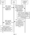
- an embodiment of this application provides a method for configuring a power consumption parameter. The following describes the method.
- a terminal device sends an expected value of a power consumption parameter to a relay device.
- the relay device receives the expected value of the power consumption parameter of the terminal device.
- the terminal device establishes a connection to the relay device, and accesses a RAN by using the relay device.
- the terminal device may be located near the relay device.
- the terminal device may establish the connection to the relay device by using various communications technologies, for example, a wireless fidelity (Wireless Fidelity, Wi-Fi) technology, a Bluetooth (Bluetooth) technology, an Ethernet technology, a zigbee (ZigBee) technology, a universal plug and play (Universal Plug and Play, UPnP) technology, a digital living network alliance (Digital Living Network Alliance, DLNA) technology, and the like.
- a wireless fidelity Wireless Fidelity, Wi-Fi
- Bluetooth Bluetooth
- Ethernet technology an Ethernet technology
- ZigBee ZigBee
- ZigBee ZigBee
- UPnP Universal Plug and Play
- UPnP digital living network alliance
- DLNA Digital Living Network Alliance
- the power consumption parameter may include at least one of PSM activation time, periodic location update timer duration, and eDRX cycle duration.
- data may be transmitted to ensure service performance, but when the terminal device and/or the relay device are/is in a sleep state, data transmission is not allowed, so that power consumption can be reduced.
- the terminal device is used as an example for describing the PSM activation time.
- a timer is started, where duration of the timer is set to a configured value of the PSM activation time.
- the terminal device enters a PSM from the idle state. In this case, the terminal device is in the sleep state, is disconnected from the relay device, and does not monitor a paging message, to reduce power consumption.
- the terminal device When the terminal device has uplink data or signaling to be transmitted to a network side, the terminal device exits the PSM, and enters the active state.
- the terminal device is still used as an example for describing the periodic location update timer duration.
- a periodic location update timer is started, where duration of the periodic location update timer is set to a configured value of the periodic location update timer duration.
- the terminal device may switch from the idle state to the active state.
- a value of periodic location update timer duration of a terminal device using a PSM technology is greater than a value of the foregoing PSM activation time. Therefore, when the terminal device enters the idle state, the terminal device starts the timer that is set to the configured value of the PSM activation time and starts the periodic location update timer, and then enters the PSM. After the timer that is set to the configured value of the PSM activation time expires, the terminal device enters the PSM from the idle state; and after the periodic location update timer expires, the terminal device switches from the PSM to the active state.
- the terminal device is still used as an example for describing the eDRX cycle duration.
- a terminal device using an eDRX technology continuously transmits data based on an eDRX cycle.
- Duration of the eDRX cycle is set to a configured value of the eDRX cycle duration.
- the terminal device In a specific time period (the terminal device is in the active state) of each eDRX cycle, the terminal device can transmit data, but in another specific time period (the terminal device is in the sleep state) of each eDRX cycle, the terminal device cannot transmit data.
- the terminal device may include all or some terminal devices that access the RAN by using the relay device.
- the terminal device may be one or more terminal devices. This is not limited herein.
- the relay device sends the expected value of the power consumption parameter of the terminal device and an expected value of the power consumption parameter of the relay device to a core network control plane device.
- the core network control plane device receives the expected value of the power consumption parameter of the relay device and the expected value of the power consumption parameter of the terminal device.
- the core network control plane device may be an MME.
- the core network control plane device may be an SGSN.
- the core network control plane device may be a CPF entity.
- the expected value of the power consumption parameter of the relay device may reflect a data transmission requirement and a power consumption reduction requirement of the relay device
- the expected value of the power consumption parameter of the terminal device may reflect a data transmission requirement and a power consumption reduction requirement of the terminal device
- the relay device may add the expected value of the power consumption parameter of the relay device and the expected value of the power consumption parameter of the terminal device to an attach request (Attach Request) message or a location update request (Location Update Request) message, and send the message to the core network control plane device.
- Attach Request an attach request
- Location Update Request Location Update Request
- the core network control plane device determines a configured value of the power consumption parameter of the relay device and a configured value of the power consumption parameter of the terminal device based on the expected value of the power consumption parameter of the relay device and the expected value of the power consumption parameter of the terminal device.
- the configured value of the power consumption parameter of the relay device is used to configure the power consumption parameter of the relay device, to reduce power consumption of the relay device.
- the configured value of the power consumption parameter of the terminal device may be the same as or different from the configured value of the power consumption parameter of the relay device, and is specifically used to configure the power consumption parameter of the terminal device, to reduce power consumption of the terminal device.
- the terminal device implements data transmission with a network by using the relay device.
- the relay device can transmit data; and when all terminal devices connected to the relay device are not allowed to transmit data, the relay device may be not allowed to transmit data.
- the configured value of the power consumption parameter of the relay device refers to the data transmission requirement and the power consumption reduction requirement of the terminal device connected to the relay device.
- the core network control plane device sends the configured value of the power consumption parameter of the relay device and the configured value of the power consumption parameter of the terminal device to the relay device.
- the relay device receives the configured value of the power consumption parameter of the relay device and the configured value of the power consumption parameter of the terminal device from the core network control plane device.
- the configured value of the power consumption parameter of the relay device and the configured value of the power consumption parameter of the terminal device may be sent to the relay device simultaneously.
- the configured value of the power consumption parameter of the relay device and the configured value of the power consumption parameter of the terminal device are carried in an attach accept (Attach Accept) message or a location update accept (Location Update Accept) message and sent to the relay device.
- the configured value of the power consumption parameter of the relay device and the configured value of the power consumption parameter of the terminal device may also be sent to the relay device separately at different times. This is not limited in this application.
- the relay device sends the configured value of the power consumption parameter of the terminal device to the terminal device.
- the terminal device receives the configured value of the power consumption parameter of the terminal device from the relay device.
- both the configured value of the power consumption parameter of the relay device and the configured value of the power consumption parameter of the terminal device that accesses the RAN by using the relay device are determined based on the expected value of the power consumption parameter of the terminal device and the expected value of the power consumption parameter of the relay device. This avoids data transmission failure caused by sending data to the network side by the terminal device through the relay device when the relay device is in the sleep state. Therefore, the method not only reduces power consumption of the relay device and the terminal device, but also ensures data transmission efficiency of the terminal device.
- the method further includes S206: The terminal device receives the configured value of the power consumption parameter from the relay device, and sets the power consumption parameter of the terminal device based on the configured value, or releases a connection between the terminal device and the relay device.
- the terminal device may be disconnected from the relay device. Further, the terminal device may reselect another relay device, and establish a connection to the reselected relay device.
- the method may further include: the relay device triggers the core network control plane device to reconfigure the power consumption parameter of the relay device and the power consumption parameter of the terminal device connected to the relay device.
- the relay device may notify the core network control plane device of the terminal device that is disconnected, and the core network control plane device excludes the expected value of the power consumption parameter of the terminal device.
- the method may further include: the relay device may instruct the terminal device to send the expected value of the power consumption parameter and perform S201 again.
- the terminal device sets the power consumption parameter of the terminal device based on the configured value in S206 specifically includes:
- the method further includes the following step: After receiving the configured value of the power consumption parameter of the relay device, the relay device sets the power consumption parameter of the relay device based on the received configured value of the power consumption parameter.
- S203 includes:
- the core network control plane device first configures the power consumption parameter of the terminal device based on the expected value of the power consumption parameter of the terminal device, so that the configured value of the power consumption parameter of the terminal device satisfies the data transmission requirement and the power consumption reduction requirement of the terminal device. Then the core network control plane device determines the configured value of the power consumption parameter of the relay device based on the configured value of the power consumption parameter of the terminal device and the expected value of the power consumption parameter of the relay device, so that the configured value of the power consumption parameter of the relay device ensures data transmission efficiency of the terminal device; in addition, the configured value of the power consumption parameter of the relay device also satisfies the power consumption reduction requirement of the relay device.
- the power consumption parameter includes the PSM activation time
- a configured value of PSM activation time of the relay device is greater than or equal to a largest one of configured values of PSM activation time of the terminal devices
- the configured value of the PSM activation time of the relay device is greater than or equal to an expected value of the PSM activation time of the relay device.
- the relay device does not enter the PSM either. To be specific, the relay device does not enter the PSM earlier than the terminal device. Therefore, data transmission efficiency of the terminal device is ensured, while power consumption of the relay device is reduced.
- the core network control plane device After performing S203, the core network control plane device sends the configured value of the power consumption parameter of the relay device and the configured value of the power consumption parameter of the terminal device to the relay device, and the relay device sends the configured value of the power consumption parameter of the terminal device to the terminal device. Because a distance between the relay device and the terminal device is relatively short, it may be considered that the relay device and the terminal device receive the configured values of their power consumption parameters simultaneously. In addition, because the relay device and the terminal device receive the configured values of their power consumption parameters simultaneously, that is, enter the idle state from a connected state simultaneously, it may be understood that the relay device and the terminal device start timers for entering PSM simultaneously.
- the power consumption parameter includes the periodic location update timer duration, a configured value of periodic location update timer duration of the relay device is less than or equal to a smallest one of configured values of periodic location update timer duration of the terminal devices, and the configured value of the periodic location update timer duration of the relay device is less than or equal to an expected value of the periodic location update timer duration of the relay device.
- the design can ensure that after both the relay device and the terminal device enter the idle state, the relay device can enter the active state earlier than the terminal device. To be specific, the relay device enters the active state when or before the terminal device enters the active state. This ensures that the relay device does not affect data transmission of the terminal device, and further ensures data transmission efficiency of the terminal device.
- the terminal device when the terminal device enters the idle state, the terminal device starts the periodic location update timer; and after the periodic location update timer expires, the terminal device enters the active state, and in this case, the terminal device can transmit data.
- the terminal device when the terminal device uses a PSM power consumption optimization manner, before the periodic location update timer expires, the terminal device may enter the PSM from the idle state; and after the periodic location update timer expires, the terminal device enters the active state from the PSM.
- the relay device and the terminal device because the relay device and the terminal device enter the idle state from the connected state simultaneously, the relay device and the terminal device start the periodic location update timers simultaneously.
- subscription data of the power consumption parameter of the terminal device and subscription data of the power consumption parameter of the relay device are further considered, to ensure that the configured value of the power consumption parameter of the relay device satisfies a requirement on the subscription data of the power consumption parameter of the relay device, and ensure that the configured value of the power consumption parameter of the terminal device satisfies a requirement on the subscription data of the power consumption parameter of the terminal device.
- that the core network control plane device determines the configured value of the power consumption parameter of the terminal device based on the expected value of the power consumption parameter of the terminal device may include:
- the core network control plane device determines the configured value of the power consumption parameter of the relay device based on the expected value of the power consumption parameter of the relay device and the configured value of the power consumption parameter of the terminal device may include: the core network control plane device determines the configured value of the power consumption parameter of the relay device based on the subscription data of the power consumption parameter of the relay device, the expected value of the power consumption parameter of the relay device, and the configured value of the power consumption parameter of the terminal device, where the configured value of the power consumption parameter of the relay device belongs to the subscription data of the power consumption parameter of the relay device.
- the subscription data of the power consumption parameter of the terminal device and the subscription data of the power consumption parameter of the relay device may be stored in the core network control plane device or an HSS.
- the core network control plane device may send a request message to obtain the subscription data of the power consumption parameter of the terminal device and the subscription data of the power consumption parameter of the relay device.
- the core network control plane device determines the configured value of the power consumption parameter of the terminal device based on the subscription data of the power consumption parameter of the terminal device and the expected value of the power consumption parameter of the terminal device specifically includes the following process: The core network control plane device determines whether the expected value belongs to the subscription data; and if the expected value belongs to the subscription data, the core network control plane device uses the expected value as the configured value (when the expected value is a specific value), or selects a largest value or a smallest value from the expected value as the configured value (when the expected value is a range). For example, when the power consumption configuration parameter is the PSM activation time, the largest value is selected; or when the power consumption configuration parameter is the periodic location update timer duration, the smallest value is selected.
- the core network control plane device selects a largest value or a smallest value from the subscription data as the configured value.
- a specific selection method is similar to the foregoing method for selecting the configured value from the expected value, and is not described again herein.
- the expected value reflects the requirement of the terminal device
- the configured value is preferentially determined in the expected value. Therefore, the method can ensure that the requirement of the terminal device is satisfied as far as possible, while ensuring that the configured value of the power consumption parameter of the terminal device belongs to the subscription data of the power consumption parameter of the terminal device.
- the core network control plane device determines that the expected value of the power consumption parameter of the relay device belongs to the subscription data of the power consumption parameter of the relay device and satisfies a condition for the configured value of the power consumption parameter of the relay device in the foregoing design
- the core network control plane device uses the expected value of the power consumption parameter of the relay device as the configured value of the power consumption parameter of the relay device (when the expected value is a specific value), or selects a largest value or a smallest value from the expected value as the configured value (when the expected value is a range).
- the core network control plane device uses the expected value of the power consumption parameter of the relay device as the configured value of the power consumption parameter of the relay device (when the expected value is a specific value), or selects a largest value or a smallest value from the expected value as the configured value (when the expected value is a range).
- the core network control plane device determines that the expected value of the power consumption parameter of the relay device does not belong to the subscription data of the power consumption parameter of the relay device, and/or that the expected value of the power consumption parameter of the relay device does not satisfy a condition for the configured value of the power consumption parameter of the relay device in the foregoing two designs
- the core network control plane device selects, from the subscription data of the power consumption parameter of the relay device, a value that satisfies the condition for the configured value of the power consumption parameter of the relay device in the foregoing design, as the configured value of the power consumption parameter of the relay device.
- the method can ensure that the requirement of the relay device is satisfied as far as possible, while ensuring that the configured value of the power consumption parameter of the relay device belongs to the subscription data of the power consumption parameter of the relay device.
- the core network control plane device considers the subscription data of the power consumption parameter of the terminal device and the subscription data of the power consumption parameter of the relay device (for example, a design of determining candidate configured values of the power consumption parameters of the terminal device and/or the relay device)
- step S203 includes at least the following three designs:
- the power consumption parameter includes the PSM activation time
- both a configured value of the PSM activation time of the relay device and a configured value of the PSM activation time of the terminal device are a larger one of an expected value of the PSM activation time of the terminal device and an expected value of the PSM activation time of the relay device.
- the method can ensure that the relay device does not enter the PSM earlier than the terminal device. Therefore, data transmission efficiency of the terminal device is ensured, while power consumption of the relay device is reduced.
- the power consumption parameter includes the periodic location update timer duration, and both a configured value of the periodic location update timer duration of the relay device and a configured value of the periodic location update timer duration of the terminal device are a smaller one of an expected value of the periodic location update timer duration of the terminal device and an expected value of the periodic location update timer duration of the relay device.
- the design can ensure that the relay device and the terminal device enter the active state simultaneously after both the relay device and the terminal device enter the idle state. This ensures that the relay device does not affect data transmission of the terminal device, and further ensures data transmission efficiency of the terminal device.
- the power consumption parameter includes the eDRX cycle duration, and both a configured value of eDRX cycle duration of the relay device and a configured value of eDRX cycle duration of the terminal device are a smaller one of an expected value of the eDRX cycle duration of the terminal device and an expected value of the eDRX cycle duration of the relay device.
- a device using the eDRX technology continuously transmits data based on an eDRX cycle, and can transmit data in a specific time period of each eDRX cycle, but cannot transmit data in another specific time period.
- duration of an eDRX cycle of the relay device needs to be the same as duration of an eDRX cycle of the terminal device.
- duration of an eDRX cycle of the relay device needs to be the same as duration of an eDRX cycle of the terminal device.
- the core network control plane device may first determine the configured value of the eDRX cycle duration of the relay device and a configured value of eDRX cycle duration of a first one of the N terminal devices, and then determine that a configured value of eDRX cycle duration of another one of the N terminal devices is equal to the configured value of the eDRX cycle duration of the first device.
- the core network control plane device first directly determines a smallest value, and then determines that both the expected value of the eDRX cycle duration of the relay device and an expected value of eDRX cycle duration of each of the N terminal devices are the smallest value.
- the eDRX cycle duration is related to a latency in receiving downlink data by the terminal device (or the relay device)
- sleep time of the terminal device is longer, and the terminal device (or the relay device) can receive downlink data only after the sleep ends. Consequently, the latency in receiving downlink data by the terminal device (or the relay device) is also higher.
- the core network control plane device determines that the configured value of the eDRX cycle duration of the relay device and the configured value of the eDRX cycle duration of the terminal device are both the smaller one of the expected value of the eDRX cycle duration of the terminal device and the expected value of the eDRX cycle duration of the relay device.
- the design can satisfy the requirements on latencies in receiving downlink data by the terminal device and the relay device, and ensure data transmission efficiency of the terminal device.
- S203 includes:
- the subscription data of the power consumption parameters of the relay device and the terminal device specifies usable values or ranges of the power consumption parameters that the relay device and the terminal device subscribe to, when the core network control plane device performs S203, the subscription data of the power consumption parameter of the terminal device and the subscription data of the power consumption parameter of the relay device further need to be considered, to further ensure that the determined configured value of the power consumption parameter of the relay device belongs to the subscription data of the power consumption parameter of the relay device, and ensure that the determined configured value of the power consumption parameter of the terminal device belongs to the subscription data of the power consumption parameter of the terminal device.
- the power consumption parameter includes the PSM activation time, and both a configured value of the PSM activation time of the relay device and a configured value of the PSM activation time of the terminal device are a larger one of a candidate configured value of the PSM activation time of the relay device and a candidate configured value of the PSM activation time of the terminal device.
- the method can ensure that the relay device does not enter the PSM earlier than the terminal device. Therefore, data transmission efficiency of the terminal device is ensured, while power consumption of the relay device is reduced.
- the power consumption parameter includes the periodic location update timer duration, and both a configured value of the periodic location update timer duration of the relay device and a configured value of the periodic location update timer duration of the terminal device are a smaller one of a candidate configured value of the periodic location update timer duration of the relay device and a candidate configured value of the periodic location update timer duration of the terminal device.
- the design can ensure that the relay device and the terminal device enter the active state simultaneously after both the relay device and the terminal device enter the idle state. This ensures that the relay device does not affect data transmission of the terminal device, and further ensures data transmission efficiency of the terminal device.
- the power consumption parameter includes the eDRX cycle duration, and both a configured value of eDRX cycle duration of the relay device and a configured value of the eDRX cycle duration of the terminal device are a smaller one of a candidate configured value of the eDRX cycle duration of the terminal device and a candidate configured value of the eDRX cycle duration of the relay device.
- the design can ensure that requirements on latencies in receiving downlink data by the terminal device and the relay device are satisfied, and ensure data transmission efficiency of the terminal device.
- the core network control plane device when the terminal device and the relay device use the eDRX technology to reduce power consumption, the core network control plane device not only needs to configure the eDRX cycle duration of the terminal device and the eDRX cycle duration of the relay device, but also needs to determine data transmission configurations in eDRX cycles of the terminal device and the relay device, for example, time of allowed uplink data transmission (for example, an activation time period), time of forbidding data transmission (for example, a sleep time period), a data forwarding time period (time of forwarding downlink data of the terminal device by the relay device to the terminal device), and the like. Therefore, data transmission efficiency of the terminal device can be further ensured.
- time of allowed uplink data transmission for example, an activation time period
- time of forbidding data transmission for example, a sleep time period
- a data forwarding time period time of forwarding downlink data of the terminal device by the relay device to the terminal device
- the method further includes: the core network control plane device determines the data transmission configurations in the eDRX cycles of the terminal device and the relay device. Specifically, the method includes but is not limited to the following two manners.
- the core network control plane device determines an activation time period and a data forwarding time period in the eDRX cycle of the relay device and a sleep time period and a data forwarding time period in the eDRX cycle of the terminal device, where the data forwarding time period in the eDRX cycle of the terminal device is the same as the data forwarding time period in the eDRX cycle of the relay device, and both duration of the eDRX cycle of the relay device and duration of the eDRX cycle of the terminal device are the configured value of the eDRX cycle duration of the relay device; and the core network control plane device sends the activation time period and the data forwarding time period in the eDRX cycle of the relay device and the sleep time period and the data forwarding time period in the eDRX cycle of the terminal device to the relay device.
- an activation time period in an eDRX cycle of any device is a time period in which the device sends uplink data in the eDRX cycle to the network;
- a sleep time period in the eDRX cycle of the device is a time period in which the device is not allowed to perform data (uplink data and downlink data) transmission in the eDRX cycle;
- a data forwarding time period in the eDRX cycle of the device may be a time period in which the device can perform downlink data transmission with another device having a same data forwarding time period.
- the data forwarding time period in the eDRX cycle of the terminal device is the same as the data forwarding time period in the eDRX cycle of the relay device. This can ensure that when the relay device receives downlink data of the terminal device from a network side (a core network user plane device), the downlink data can be forwarded to the terminal device in the data forwarding time period of the relay device.
- a network side a core network user plane device
- N terminal devices access a RAN by using a relay device.
- a data forwarding time period in an eDRX cycle of the relay terminal devices may be divided into a plurality of sub time periods. Each sub time period may be the same as data forwarding time periods of some of the N terminal devices.
- data forwarding time T3 of the relay device is divided into two sub time periods T31 and T32.
- T31 the relay device may forward downlink data that needs to be sent to a terminal device B to the terminal device B.
- T32 the relay device may forward downlink data that needs to be sent to a terminal device A to the terminal device A.
- the data forwarding time period in the eDRX cycle of the relay device may be the same as a data forwarding time period of each of the N terminal devices, as shown in FIG. 4 .
- the eDRX cycle of the relay device includes three time periods: the activation time period, a sleep time period, and the data forwarding time period. Therefore, the core network control plane device may determine only the activation time period and the data forwarding time period in the eDRX cycle of the relay device. Therefore, after the relay device receives the activation time period and the data forwarding time period in the eDRX cycle of the relay device, the relay device may also obtain the sleep time period in the eDRX cycle of the relay device by using the two time periods.
- the eDRX cycle of the terminal device may not include an activation time period.
- FIG. 3 and FIG. 4 are schematic diagrams of data transmission configurations in eDRX cycles of two terminal devices and a relay device.
- the core network control plane device further needs to reserve, in the eDRX cycle of the terminal device, the activation time period in the eDRX cycle of the terminal device, and ensure that an intersection set exists between activation time periods in the eDRX cycles of the N terminal devices and the activation time period in the eDRX cycle of the relay device.
- FIG. 5 is a schematic diagram of data transmission configurations in eDRX cycles of two terminal devices and a relay device. This can ensure that when the terminal device in the activation time period needs to send uplink data to the network side, the relay device is also in the activation time period, and can transmit the uplink data of the terminal device.
- the terminal device may send uplink data to the relay device in the data forwarding time period, and the relay device also forwards the uplink data to the network side in the data forwarding time period.
- the relay device may also receive, in the data forwarding time period in the eDRX cycle, downlink data of the relay device and/or the terminal device that is sent by the network side, to reduce a latency in transmitting downlink data, and improve efficiency of forwarding the downlink data.
- the core network control plane device determines a sleep time period and a data forwarding time period in the eDRX cycle of the relay device and a sleep time period and a data forwarding time period in the eDRX cycle of the terminal device, where the data forwarding time period in the eDRX cycle of the terminal device is the same as the data forwarding time period in the eDRX cycle of the relay device, and both duration of the eDRX cycle of the relay device and duration of the eDRX cycle of the terminal device are the configured value of the eDRX cycle duration of the relay device; and the core network control plane device sends the sleep time period and the data forwarding time period in the eDRX cycle of the relay device and the sleep time period and the data forwarding time period in the eDRX cycle of the terminal device to the relay device.
- the core network control plane device may send content determined in the manner 1 or the manner 2 to the relay device.
- the relay device After receiving the sleep time period and the data forwarding time period in the eDRX cycle of the terminal device, the relay device sends the sleep time period and the data forwarding time period in the eDRX cycle of the terminal device to the terminal device.
- the core network control plane device determines the sleep time period and the data forwarding time period in the eDRX cycle of the relay device, but in the manner 1, the core network control plane device determines the activation time period and the data forwarding time period in the eDRX cycle of the relay device. Therefore, mutual reference may be made for the two manners. Details are not described again herein.
- the eDRX cycle of the relay device includes three time periods: an activation time period, the sleep time period, and the data forwarding time period. Therefore, the core network control plane device may also determine the sleep time period and the data forwarding time period in the eDRX cycle of the relay device. Therefore, after the relay device receives the sleep time period and the data forwarding time period in the eDRX cycle of the relay device, the relay device may also obtain the activation time period in the eDRX cycle of the relay device by using the two time periods.
- the core network control plane device may determine the data transmission configurations in the eDRX cycles of the terminal device and the relay device, to further ensure data transmission efficiency of the terminal device.
- the core network control plane device may determine the sleep time period in the eDRX cycle of the terminal device and the activation time period (or the sleep time period) in the eDRX cycle of the relay device by using the following method:
- the core network control plane device determines the sleep time period in the eDRX cycle of the terminal device and the activation time period (or the sleep time period) in the eDRX cycle of the relay device based on power consumption status information of the terminal device and the relay device, where the power consumption status information includes at least one of the following: information about remaining power of a battery, a battery type, and a device type.
- the information about the remaining power of the battery may be a percentage of the remaining power of the battery, a status of the remaining power of the battery, a value of the remaining power of the battery, or the like.
- the battery type may be whether the battery is chargeable, whether the battery can be used repeatedly, or the like.
- a type of the terminal device includes a mobile phone, a wearable device, or the like.
- the core network may set a sleep time period of the terminal device A to be longer than a sleep time period of the terminal device B.
- the core network may set a sleep time period of the terminal device A to be shorter than a sleep time period of the terminal device B.
- the core network control plane device may determine the sleep time period in the eDRX cycle of the terminal device and the activation time period (or the sleep time period) in the eDRX cycle of the relay device based on the power consumption status information of the terminal device and the relay device. Therefore, power of the battery of the terminal device can be utilized properly, and utilization of the battery is improved.
- the core network control plane device may determine the data forwarding time periods in the eDRX cycles of the terminal device and the relay device by using the following method:
- the core network control plane device determines the data forwarding time period in the eDRX cycle of the terminal device based on service feature parameters of the terminal device and the relay device, where the service feature parameters include at least one of the following: communication duration and communication data amount information (for example, information such as a size of a communication data packet and a quantity of data packets).
- the core network control plane device may determine the data forwarding time periods in the eDRX cycles of the terminal device and the relay device based on the service feature parameters of the terminal device and the relay device. Therefore, the data forwarding time periods can be utilized properly, and resource utilization is improved.
- a plurality of terminal devices using the eDRX technology exist in a relatively small space range. Any one of the terminal devices may serve as a relay device for transmitting data of another terminal device.
- each terminal device may access the network in the foregoing two manners. How to configure eDRX cycles of the plurality of terminal devices to optimize power consumption of the plurality of terminal devices and ensure data transmission efficiency of the plurality of terminal devices in the scenarios is also a problem urgently to be resolved in this field.
- this application further provides another method for configuring a power consumption parameter, as shown in FIG. 6 .
- a core network control plane device receives expected values of eDRX cycle duration of N terminal devices, where N is an integer greater than or equal to 2.
- the core network control plane device may receive the expected values of the eDRX cycle duration of the N terminal devices in the following two manners.
- Manner a The core network control plane device receives the expected values of the eDRX cycle duration of the N terminal devices that are sent by one of the N terminal devices.
- each of other terminal devices than the terminal device N of the N terminal devices sends its expected value of eDRX cycle duration to the terminal device N; and in S601a, the terminal device N sends the expected values of the eDRX cycle duration of the N terminal devices (including the terminal device N and other terminal devices connected to the terminal device N) to the core network control plane device.
- Manner b The core network control plane device separately receives an expected value of eDRX cycle duration that is sent by each of the N terminal devices, where the eDRX cycle duration is eDRX cycle duration of the corresponding terminal device. As shown in the figure, in S601b, the core network control plane device separately receives an expected value of eDRX cycle duration of a terminal device 1 that is sent by the terminal device 1, and an expected value of eDRX cycle duration of a terminal device N that is sent by the terminal device N.
- the core network control plane device determines a configured value of the eDRX cycle duration based on the expected values of the eDRX cycle duration of the N terminal devices.
- Each of the N terminal devices may serve as a relay device for transmitting data of another terminal device. Therefore, as can be known from a principle for configuring the eDRX cycle duration of the N terminal devices and the relay device in the embodiment shown in FIG. 2 , to ensure data transmission efficiency of the N terminal devices, the eDRX cycle duration of the relay device needs to be the same as the eDRX cycle duration of all the N terminal devices. Therefore, in this embodiment of this application, to ensure data transmission efficiency of the N terminal devices, the configured value of the eDRX cycle duration determined by the core network control plane device is applicable to the N terminal devices. To be specific, configured values of the eDRX cycle duration of the N terminal devices are the same.
- the configured value of the eDRX cycle duration determined by the core network control plane device is a smallest one of the expected values of the eDRX cycle duration of the N terminal devices.
- the core network control plane device determines that the configured value of the eDRX cycle duration is the smallest one of the expected values of the eDRX cycle duration of the N terminal devices.
- the method can satisfy requirements on latencies in receiving downlink data by the N terminal devices, and ensure data transmission efficiency of the N terminal devices.
- subscription data of the eDRX cycle duration of the N terminal devices further needs to be considered, to ensure that the determined configured value of the eDRX cycle duration satisfies a requirement of the subscription data of the eDRX cycle duration of the N terminal devices.
- that the core network control plane device determines a configured value of the eDRX cycle duration based on the expected values of the eDRX cycle duration of the N terminal devices includes the following steps:
- the foregoing steps can ensure that the configured value of the eDRX cycle duration belongs to the subscription data of the eDRX cycle duration of the N devices.
- the configured value of the eDRX cycle duration is a smallest one of the candidate configured values of the eDRX cycle duration of the N terminal devices. Therefore, the configured value of the eDRX cycle duration can satisfy requirements on latencies in receiving downlink data by the N terminal devices, and ensure data transmission efficiency of the N terminal devices.
- the core network control plane device sends the configured value of the eDRX cycle duration to the N terminal devices.
- the core network control plane device may perform S603 in the following two manners.
- Manner a The core network control plane device sends the configured value of the eDRX cycle duration to one of the N terminal devices, and then the terminal device sends the configured value of the eDRX cycle duration to another terminal device of the N terminal devices.
- the core network control plane device sends the configured value of the eDRX cycle duration to the terminal device N of the N terminal devices; and then in S603a0, the terminal device N sends the configured value of the eDRX cycle duration to another terminal device (including the terminal device 1).
- Manner b The core network control plane device sends the configured value of the eDRX cycle duration to each of the N terminal devices separately. As shown in the figure, in S603b, the core network control plane device sends the configured value of the eDRX cycle duration to the terminal device 1 and sends the configured value of the eDRX cycle duration to the terminal device N separately.
- the N terminal devices set the eDRX cycle duration based on the configured value of the eDRX cycle duration.
- the method further includes:
- the data forwarding time period in the eDRX cycle of each of the N terminal devices is the same as the data forwarding time period in the eDRX cycle of at least one other terminal device of the N terminal devices. This can ensure that a plurality of terminal devices having a same data forwarding time period in eDRX cycles may perform downlink data forwarding.
- data received by a terminal device in an activation time period in the plurality of terminal devices may be forwarded to another terminal device in the data forwarding time period.
- each of the N terminal devices may send uplink data to the core network user plane device in the activation time period in the eDRX cycle; or each terminal device sends uplink data to the core network user plane device in the data forwarding time period in the eDRX cycle. This is not limited in this application.
- a mobile communications system includes two terminal devices: a terminal device A and a terminal device B; in this case, after the core network control plane device determines a configured value T of eDRX cycle duration of the two terminal devices, the core network control plane device determines that an activation time period, a sleep time period, and a data forwarding time period of each terminal device in T satisfy the foregoing two conditions, as shown in FIG. 7 .
- the terminal device A In a time period T1 in an eDRX cycle T, the terminal device A is in the activation time period and may receive first data sent by the core network user plane device in the mobile communications system, and the terminal device B is in the sleep time period; in a time period T2, the terminal device B is in the activation time period and may receive second data sent by the core network user plane device, and the terminal device A is in the sleep time period; and in a time period T3, the terminal device A and the terminal device B are both in the data forwarding time period, the terminal device A may send the received first data to the terminal device B, and the terminal device B may also send the received second data to the terminal device A.
- one data forwarding time period may exist.
- data forwarding time periods of the N terminal device overlap each other.
- a plurality of data forwarding time periods may also exist. This is not limited.
- each data forwarding time period specifies a data forwarding direction.
- the terminal device A can send data to the terminal device B in one direction only, as shown in the following example 2.
- each data forwarding time period specifies some terminal devices that perform data forwarding. For example, in a data forwarding time period, three of five terminal devices can forward data to each other, and in another data forwarding time period, the other two terminal devices forward data to each other.
- Example 2 Still using a scenario of the example 1 as an example, the core network control plane device determines that an activation time period, a sleep time period, and a data forwarding time period of each terminal device in T satisfy the foregoing two conditions, as shown in FIG. 8 .
- the terminal device A is in the activation time period and may receive first data sent by the core network user plane device in the mobile communications system, and the terminal device B is in the sleep time period; in a time period T2, the terminal device A and the terminal device B are both in the sleep time period; in a time period T3, the terminal device A and the terminal device B are both in the data forwarding time period, and the terminal device A may send the received first data to the terminal device B; in a time period T4, the terminal device B is in the activation time period and may receive second data sent by the core network user plane device in the mobile communications system, and the terminal device A is in the sleep time period; in a time period T5, the terminal device A and the terminal device B are both in the sleep time period; and in a time period T6, the terminal device A and the terminal device B are both in the data forwarding time period, and the terminal device B may send the received second data to the terminal device A.
- a mobile communications system includes three terminal devices: a terminal device A, a terminal device B, and a terminal device C; in this case, after the core network control plane device determines a configured value T of eDRX cycle duration of the three terminal devices, the core network control plane device determines that an activation time period, a sleep time period, and a data forwarding time period of each terminal device in an eDRX cycle T satisfy the foregoing two conditions, as shown in FIG. 9 .
- the terminal device A is in the activation time period and may receive first data sent by the core network user plane device in the mobile communications system, and the terminal device B and the terminal device C are in the sleep time period; in a time period T2, the terminal device B is in the activation time period and may receive second data send by the core network user plane device, and the terminal device A and the terminal device C are in the sleep time period; in a time period T3, the terminal device C is in the activation time period and may receive third data sent by the core network user plane device, and the terminal device A and the terminal device B are in the sleep time period; in a time period T4, the terminal device A, the terminal device B, and the terminal device C are all in the data forwarding time period, the terminal device A may send the received first data to the terminal device B or the terminal device C, the terminal device B may also send the received second data to the terminal device A or the terminal device C, and the terminal device C may also send the received third data to the terminal device A or the
- manners of configuring the activation time periods, the sleep time periods, and the data forwarding time periods in the eDRX cycles of the plurality of terminal devices shown in FIG. 7 to FIG. 9 are only several examples of this embodiment of this application, and the method for configuring the activation time periods, the sleep time periods, and the data forwarding time periods in the eDRX cycles of the plurality of terminal devices is not limited. Many other configuration manners satisfying the foregoing two conditions are also available, and are not illustrated in this embodiment of this application.
- the core network control plane device may determine the activation time periods in the eDRX cycles of the N terminal devices by using the following method:
- the core network control plane device determines the activation time periods in the eDRX cycles of the N terminal devices based on power consumption status information of the N terminal devices, where the power consumption status information includes at least one of the following: information about remaining power of a battery, a battery type, and a device type.
- the information about the remaining power of the battery may be a percentage of the remaining power of the battery, a status of the remaining power of the battery, a value of the remaining power of the battery, or the like.
- the battery type may be whether the battery is chargeable, whether the battery can be used repeatedly, or the like.
- a type of the terminal device includes a mobile phone, a wearable device, or the like.
- the core network may set an activation time period of the terminal device A to be shorter than an activation time period of the terminal device B.
- the core network may set an activation time period of the terminal device A to be longer than an activation time period of the terminal device B.
- the core network control plane device may determine an activation time period in the eDRX cycle of each terminal device based on power consumption status information of each terminal device. Therefore, power of a battery of each terminal device can be utilized properly, and utilization of the battery is improved.
- the core network control plane device may determine the data forwarding time periods in the eDRX cycles of the N terminal devices by using the following method: The core network control plane device determines the data forwarding time periods in the eDRX cycles of the N terminal devices based on service feature parameters of the N terminal devices, where the service feature parameters include at least one of the following: communication duration and communication data amount information (for example, information such as a size of a communication data packet and a quantity of data packets).
- the core network control plane device may determine a data forwarding time period in an eDRX cycle of each terminal device based on a service feature parameter of each terminal device. Therefore, data forwarding time can be utilized properly, and resource utilization is improved.
- the method further includes:
- the core network control plane device may determine, based on an overlapping relationship between the data forwarding time periods in the eDRX cycles of the N terminal devices, the forwarding terminal device that is in the activation time period and can be paged, so that the core network user plane device can first send the downlink data to the forwarding terminal device. Therefore, in data forwarding time periods in eDRX cycles of the forwarding terminal device and the target terminal device, the forwarding terminal device sends the downlink data to the target terminal device. This can ensure that the downlink data in the core network user plane device can be delivered to the terminal device in time, and prevent the core network user plane device from buffering excessive downlink data.
- a procedure for sending downlink data for a target terminal device includes the following steps, as shown in FIG. 10 .
- the core network user plane device receives downlink data of a target terminal device, where the target terminal device is one of the N terminal devices.
- the core network user plane device sends a downlink data notification message to the core network control plane device, to notify the core network control plane device that the core network user plane device has received the downlink data of the target terminal device.
- the core network control plane device determines a forwarding terminal device from the N terminal devices based on an activation time period, a sleep time period, and a data forwarding time period in an eDRX cycle of each of the N terminal devices.
- the forwarding terminal device is in an activation time period, and a data forwarding time period of the forwarding terminal device is the same as a data forwarding time period of the target terminal device.
- the core network control plane device sends a paging message to a RAN device accessed by the forwarding terminal device, where the paging message includes an identifier of the forwarding terminal device.
- the RAN device sends the paging message to the forwarding terminal device.
- the forwarding terminal device sends a service request (Service Request) message to the core network control plane device.
- Service Request Service Request
- the core network control plane device sends a modify bearer request (Modify Bearer Request) message to the core network user plane device to notify an address of the RAN device, to implement forwarding of the downlink data.
- modify bearer request Modify Bearer Request
- the core network user plane device feeds back a modify bearer response (Modify Bearer Response) message.
- modify bearer response Modify Bearer Response
- the core network user plane device may send the downlink data to the RAN device based on the address of the RAN device, and the RAN device forwards the downlink data to the forwarding terminal device.
- the forwarding terminal device buffers the downlink data.
- the forwarding terminal device sends the downlink data to the target terminal device when the forwarding terminal device is in the data forwarding time period.
- the core network control plane device may determine, based on an overlapping relationship between the data forwarding time periods in the eDRX cycles of the N terminal devices, the forwarding terminal device that is in the activation time period and can be paged, so that the core network user plane device can first send the downlink data to the forwarding terminal device. Therefore, in data forwarding time periods in eDRX cycles of the forwarding terminal device and the target terminal device, the forwarding terminal device sends the downlink data to the target terminal device. This can ensure that the downlink data in the core network user plane device can be delivered to the terminal device in time, and prevent the core network user plane device from buffering excessive downlink data.
- a subsequent paging procedure for the terminal device uses paging based on a temporary mobile subscriber identity (Serving-Temporary Mobile Subscriber Identity, S-TMSI).
- S-TMSI Serving-Temporary Mobile Subscriber Identity
- a paging message sent by a core network control plane device in the mobile communications system carries an S-TMSI of the terminal device.
- the core network control plane device stores the S-TMSI of the terminal device.
- the S-TMSI of the terminal device that is previously stored by the core network control plane device also disappears. Consequently, the core network control plane device cannot continue to use paging based on the S-TMSI, and the eDRX function and service processing of the terminal device are further affected.
- an embodiment of this application further provides two methods for configuring a power consumption parameter.
- the first method includes:
- the second method includes:
- the system broadcast message indicates that the eDRX function of the RAN device is not enabled, so that a terminal device and a relay device accessing the RAN device do not enable or stop the eDRX function either.
- the relay device after receiving the system broadcast message of the RAN device, the relay device that accesses the RAN device does not enable the eDRX function based on the system broadcast message.
- the relay device may send an eDRX deactivation indication to a connected terminal device, so that the terminal device does not enable the eDRX function.
- the RAN device after fault recovery of the core network control plane device in the mobile communications system, the RAN device sends the system broadcast message to instruct the relay device and the terminal device accessing the RAN device not to enable the eDRX function. This prevents the relay device and the terminal device in the mobile communications system from continuing to enable the eDRX function, and avoids impact on service processing of the terminal device.
- an embodiment of this application further provides a core network control plane device.
- the core network control plane device is configured to implement the method for configuring a power consumption parameter as shown in FIG. 2 .
- the core network control plane device 1100 includes a receiving unit 1101, a processing unit 1102, and a sending unit 1103.
- the receiving unit 1101 is configured to receive an expected value of a power consumption parameter of a relay device and an expected value of a power consumption parameter of a terminal device.
- the processing unit 1102 is configured to determine a configured value of the power consumption parameter of the relay device and a configured value of the power consumption parameter of the terminal device based on the expected value of the power consumption parameter of the relay device and the expected value of the power consumption parameter of the terminal device.
- the sending unit 1103 is configured to send the configured value of the power consumption parameter of the relay device and the configured value of the power consumption parameter of the terminal device to the relay device.
- the power consumption parameter includes at least one of power saving mode PSM activation time, periodic location update timer duration, and extended discontinuous reception eDRX cycle duration.
- processing unit 1102 is specifically configured to:
- the determining the configured value of the power consumption parameter of the terminal device based on the expected value of the power consumption parameter of the terminal device includes:
- the power consumption parameter includes the PSM activation time, and both a configured value of PSM activation time of the relay device and a configured value of PSM activation time of the terminal device are a larger one of an expected value of the PSM activation time of the terminal device and an expected value of the PSM activation time of the relay device; or
- processing unit 1102 is specifically configured to:
- the power consumption parameter includes the PSM activation time, and both a configured value of PSM activation time of the relay device and a configured value of PSM activation time of the terminal device are a larger one of a candidate configured value of the PSM activation time of the relay device and a candidate configured value of the PSM activation time of the terminal device; or
- the power consumption parameter includes the eDRX cycle duration
- the core network control plane device when the core network control plane device determines the configured value of the power consumption parameter of the relay device and the configured value of the power consumption parameter of the terminal device, the expected value of the power consumption parameter of the terminal device and the expected value of the power consumption parameter of the relay device are considered.
- the expected value of the power consumption parameter of the terminal device may reflect a data transmission requirement and a power consumption reduction requirement of the terminal device
- the expected value of the power consumption parameter of the relay device may reflect a data transmission requirement and a power consumption reduction requirement of the relay device. Therefore, the configured value of the power consumption parameter of the relay device satisfies the data transmission requirement of the terminal device, and ensures data transmission efficiency of the terminal device.
- the configured value of the power consumption parameter of the relay device and the configured value of the power consumption parameter of the terminal device also satisfy the power consumption reduction requirements of the relay device and the terminal device.
- an embodiment of this application further provides a terminal device.
- the terminal device is configured to implement the method for configuring a power consumption parameter as shown in FIG. 2 .
- the terminal device 1200 includes a sending unit 1201, a receiving unit 1202, and a processing unit 1203.
- the sending unit 1201 is configured to send an expected value of a power consumption parameter to a relay device.
- the receiving unit 1202 is configured to receive a configured value of the power consumption parameter of the terminal device from the relay device.
- the processing unit 1203 is configured to set the power consumption parameter of the terminal device based on the configured value, or release a connection between the terminal device and the relay device.
- the power consumption parameter includes at least one of power saving mode PSM activation time, periodic location update timer duration, and extended discontinuous reception eDRX cycle duration.
- the receiving unit 1202 is further configured to: receive a sleep time period and a data forwarding time period in an eDRX cycle of the terminal device from the relay device.
- the terminal device may send the expected value of the power consumption parameter to a core network control plane device through the relay device, so that when the core network control plane device determines a configured value of a power consumption parameter of the relay device and the configured value of the power consumption parameter of the terminal device, the expected value of the power consumption parameter of the terminal device and an expected value of the power consumption parameter of the relay device are considered.
- This can not only reduce power consumption of the terminal device, but also avoid data transmission failure caused by sending data to a network side by the terminal device through the relay device when the relay device is in a sleep state, and ensure data transmission efficiency of the terminal device.
- an embodiment of this application further provides a relay device.
- the relay device is configured to implement the method for configuring a power consumption parameter as shown in FIG. 2 .
- the terminal device 1300 includes a receiving unit 1301 and a sending unit 1302.
- the receiving unit 1301 is configured to receive an expected value of a power consumption parameter of a terminal device.
- the sending unit 1302 is configured to send the expected value of the power consumption parameter of the terminal device and an expected value of the power consumption parameter of the relay device to a core network control plane device.
- the receiving unit 1301 is further configured to receive a configured value of the power consumption parameter of the relay device and a configured value of the power consumption parameter of the terminal device from the core network control plane device.
- the sending unit 1302 is further configured to send the configured value of the power consumption parameter of the terminal device to the terminal device.
- the power consumption parameter includes at least one of power saving mode PSM activation time, periodic location update timer duration, and extended discontinuous reception eDRX cycle duration.
- the receiving unit 1301 is further configured to:
- the relay device may send the expected value of the power consumption parameter of the relay device and the expected value of the power consumption parameter of the terminal device to the core network control plane device, so that when the core network control plane device determines the configured value of the power consumption parameter of the relay device and the configured value of the power consumption parameter of the terminal device, the expected value of the power consumption parameter of the terminal device and the expected value of the power consumption parameter of the relay device are considered.
- This can not only reduce power consumption of the relay device and the terminal device, but also avoid data transmission failure caused by sending data to a network side by the terminal device through the relay device when the relay device is in a sleep state, and ensure data transmission efficiency of the terminal device.
- an embodiment of this application further provides a RAN device.
- the RAN device is configured to implement the method for configuring a power consumption parameter.
- the RAN device 1400 includes a receiving unit 1401 and a processing unit 1402.
- the receiving unit 1401 is configured to receive extended discontinuous reception eDRX deactivation information sent by a core network control plane device.
- the processing unit 1402 is configured to broadcast a system broadcast message based on the eDRX deactivation information, where the system broadcast message indicates that an eDRX function of the RAN device is not enabled.
- the RAN device after fault recovery of the core network control plane device in a mobile communications system, the RAN device sends the system broadcast message to instruct a relay device and a terminal device accessing the RAN device not to enable the eDRX function. This prevents the relay device and the terminal device in the mobile communications system from continuing to enable the eDRX function, and avoids impact on service processing of the terminal device.
- an embodiment of this application further provides a RAN device.
- the RAN device is configured to implement the method for configuring a power consumption parameter.
- the RAN device 1500 includes a receiving unit 1501 and a processing unit 1502.
- the receiving unit 1501 is configured to receive a paging message sent by a core network control plane device, where the paging message carries an international mobile subscriber identity IMSI of a terminal device.
- the processing unit 1502 is configured to broadcast a system broadcast message when an extended discontinuous reception eDRX function of the RAN device is enabled, where the system broadcast message indicates that the eDRX function of the RAN device is not enabled.
- the RAN device after fault recovery of the core network control plane device in a mobile communications system, the RAN device sends the system broadcast message to instruct a relay device and the terminal device accessing the RAN device not to enable the eDRX function. This prevents the relay device and the terminal device in the mobile communications system from continuing to enable the eDRX function, and avoids impact on service processing of the terminal device.
- unit division is an example, and is merely logical function division. In actual implementation, another division manner may be used.
- Functional units in the embodiments of this application may be integrated into one processing unit, or each of the units may exist alone physically, or two or more units are integrated into one unit.
- the integrated unit may be implemented in a form of hardware, or may be implemented in a form of a software functional unit.
- the integrated unit When the integrated unit is implemented in the form of a software functional unit and sold or used as an independent product, the integrated unit may be stored in a computer-readable storage medium. Based on such an understanding, the technical solutions of this application essentially, or the part contributing to the prior art, or all or some of the technical solutions may be implemented in the form of a software product.
- the computer software product is stored in a storage medium and includes several instructions for instructing a computer device (which may be a personal computer, a server, a network device, or the like) or a processor (processor) to perform all or some of the steps of the methods described in the embodiments of this application.
- the foregoing storage medium includes any medium that can store program code, such as a USB flash drive, a removable hard disk, a read-only memory (Read-Only Memory, ROM), a random access memory (Random Access Memory, RAM), a magnetic disk, or an optical disc.
- program code such as a USB flash drive, a removable hard disk, a read-only memory (Read-Only Memory, ROM), a random access memory (Random Access Memory, RAM), a magnetic disk, or an optical disc.
- an embodiment of this application further provides a core network control plane device.
- the core network control plane device is configured to implement the method for configuring a power consumption parameter as shown in FIG. 2 , and has a function of the core network control plane device 1100 shown in FIG. 11 .
- the core network control plane device includes a communications interface 1601, a processor 1602, and a memory 1604.
- the communications interface 1601, the processor 1602, and the memory 1604 are interconnected.
- the communications interface 1601, the processor 1602, and the memory 1604 are interconnected by a bus 1603.
- the bus 1603 may be a peripheral component interconnect (peripheral component interconnect, PCI) standard bus, an extended industry standard architecture (extended industry standard architecture, EISA) bus, or the like.
- PCI peripheral component interconnect
- EISA extended industry standard architecture
- the bus may be classified into an address bus, a data bus, a control bus, and the like. For ease of representation, only one thick line is used to represent the bus in FIG. 16 , but this does not mean that there is only one bus or only one type of bus.
- the communications interface 1601 is configured to communicate and interact with another device such as a relay device.
- the processor 1602 is configured to implement the method for configuring a power consumption parameter as shown in FIG. 2 , including:
- the power consumption parameter includes at least one of power saving mode PSM activation time, periodic location update timer duration, and extended discontinuous reception eDRX cycle duration.
- the determining a configured value of the power consumption parameter of the relay device and a configured value of the power consumption parameter of the terminal device based on the expected value of the power consumption parameter of the relay device and the expected value of the power consumption parameter of the terminal device includes:
- the determining the configured value of the power consumption parameter of the terminal device based on the expected value of the power consumption parameter of the terminal device includes:
- the power consumption parameter includes the PSM activation time, and both a configured value of PSM activation time of the relay device and a configured value of PSM activation time of the terminal device are a larger one of an expected value of the PSM activation time of the terminal device and an expected value of the PSM activation time of the relay device; or
- the determining a configured value of the power consumption parameter of the relay device based on the expected value of the power consumption parameter of the relay device and the expected value of the power consumption parameter of the terminal device includes:
- the power consumption parameter includes the PSM activation time, and both a configured value of PSM activation time of the relay device and a configured value of PSM activation time of the terminal device are a larger one of a candidate configured value of the PSM activation time of the relay device and a candidate configured value of the PSM activation time of the terminal device; or
- the processor 1602 is further configured to:
- the memory 1604 is configured to store an application program or the like.
- the application program may include program code, and the program code includes a computer operation instruction.
- the memory 1604 may include a random access memory (random access memory, RAM), or may further include a non-volatile memory (non-volatile memory), for example, at least one magnetic disk memory.
- the processor 1602 executes the application program stored in the memory 1604 to implement the foregoing function, to implement the method for configuring a power consumption parameter as shown in FIG. 2 .
- the core network control plane device when the core network control plane device determines the configured value of the power consumption parameter of the relay device and the configured value of the power consumption parameter of the terminal device, the expected value of the power consumption parameter of the terminal device and the expected value of the power consumption parameter of the relay device are considered.
- the expected value of the power consumption parameter of the terminal device may reflect a data transmission requirement and a power consumption reduction requirement of the terminal device
- the expected value of the power consumption parameter of the relay device may reflect a data transmission requirement and a power consumption reduction requirement of the relay device. Therefore, the configured value of the power consumption parameter of the relay device satisfies the data transmission requirement of the terminal device, and ensures data transmission efficiency of the terminal device.
- the configured value of the power consumption parameter of the relay device and the configured value of the power consumption parameter of the terminal device also satisfy the power consumption reduction requirements of the relay device and the terminal device.
- an embodiment of this application further provides a terminal device.
- the terminal device is configured to implement the method for configuring a power consumption parameter as shown in FIG. 2 , and has a function of the terminal device 1200 shown in FIG. 12 .
- the terminal device includes a transceiver 1701, a processor 1702, and a memory 1704.
- the transceiver 1701, the processor 1702, and the memory 1704 are interconnected.
- the transceiver 1701, the processor 1702, and the memory 1704 are interconnected by a bus 1703.
- the bus 1703 may be a PCI bus, an EISA bus, or the like.
- the bus may be classified into an address bus, a data bus, a control bus, and the like. For ease of representation, only one thick line is used to represent the bus in FIG. 17 , but this does not mean that there is only one bus or only one type of bus.
- the transceiver 1701 is configured to communicate and interact with a relay device.
- the processor 1702 is configured to implement the method for configuring a power consumption parameter as shown in FIG. 2 , including:
- the power consumption parameter includes at least one of power saving mode PSM activation time, periodic location update timer duration, and extended discontinuous reception eDRX cycle duration.
- the processor 1702 is further configured to: receive a sleep time period and a data forwarding time period in an eDRX cycle of the terminal device from the relay device.
- the memory 1704 is configured to store an application program or the like.
- the application program may include program code, and the program code includes a computer operation instruction.
- the memory 1704 may include a RAM, or may further include a non-volatile memory, for example, at least one magnetic disk memory.
- the processor 1702 executes the application program stored in the memory 1704 to implement the foregoing function, to implement the method for configuring a power consumption parameter as shown in FIG. 2 .
- the terminal device may send the expected value of the power consumption parameter to a core network control plane device through the relay device, so that when the core network control plane device determines a configured value of a power consumption parameter of the relay device and the configured value of the power consumption parameter of the terminal device, the expected value of the power consumption parameter of the terminal device and an expected value of the power consumption parameter of the relay device are considered.
- This can not only reduce power consumption of the terminal device, but also avoid data transmission failure caused by sending data to a network side by the terminal device through the relay device when the relay device is in a sleep state, and ensure data transmission efficiency of the terminal device.
- an embodiment of this application further provides a relay device.
- the relay device is configured to implement the method for configuring a power consumption parameter as shown in FIG. 2 , and has a function of the relay device 1300 shown in FIG. 13 .
- the relay device 1800 includes a transceiver 1801, a processor 1802, and a memory 1804.
- the transceiver 1801, the processor 1802, and the memory 1804 are interconnected.
- the transceiver 1801, the processor 1802, and the memory 1804 are interconnected by a bus 1803.
- the bus 1803 may be a PCI bus, an EISA bus, or the like.
- the bus may be classified into an address bus, a data bus, a control bus, and the like. For ease of representation, only one thick line is used to represent the bus in FIG. 18 , but this does not mean that there is only one bus or only one type of bus.
- the transceiver 1801 is configured to communicate and interact with a core network control plane device.
- the processor 1802 is configured to implement the method for configuring a power consumption parameter as shown in FIG. 2 , including:
- the power consumption parameter includes at least one of power saving mode PSM activation time, periodic location update timer duration, and extended discontinuous reception eDRX cycle duration.
- the processor 1802 is further configured to:
- the memory 1804 is configured to store an application program or the like.
- the application program may include program code, and the program code includes a computer operation instruction.
- the memory 1804 may include a RAM, or may further include a non-volatile memory, for example, at least one magnetic disk memory.
- the processor 1802 executes the application program stored in the memory 1804 to implement the foregoing function, to implement the method for configuring a power consumption parameter as shown in FIG. 2 .
- the relay device may send the expected value of the power consumption parameter of the relay device and the expected value of the power consumption parameter of the terminal device to the core network control plane device, so that when the core network control plane device determines the configured value of the power consumption parameter of the relay device and the configured value of the power consumption parameter of the terminal device, the expected value of the power consumption parameter of the terminal device and the expected value of the power consumption parameter of the relay device are considered.
- This can not only reduce power consumption of the relay device and the terminal device, but also avoid data transmission failure caused by sending data to a network side by the terminal device through the relay device when the relay device is in a sleep state, and ensure data transmission efficiency of the terminal device.
- an embodiment of this application further provides a RAN device.
- the RAN device is configured to implement the method for configuring a power consumption parameter in the foregoing embodiment, and has a function of the RAN device 1400 shown in FIG. 14 .
- the RAN device includes a transceiver 1901, a processor 1902, and a memory 1904.
- the transceiver 1901, the processor 1902, and the memory 1904 are interconnected.
- the transceiver 1901, the processor 1902, and the memory 1904 are interconnected by a bus 1903.
- the bus 1903 may be a PCI bus, an EISA bus, or the like.
- the bus may be classified into an address bus, a data bus, a control bus, and the like. For ease of representation, only one thick line is used to represent the bus in FIG. 19 , but this does not mean that there is only one bus or only one type of bus.
- the transceiver 1901 is configured to communicate and interact with another device such as a core network control plane device.
- the processor 1902 is configured to implement the method for configuring a power consumption parameter in the foregoing embodiment, including:
- the memory 1904 is configured to store an application program or the like.
- the application program may include program code, and the program code includes a computer operation instruction.
- the memory 1904 may include a RAM, or may further include a non-volatile memory, for example, at least one magnetic disk memory.
- the processor 1902 executes the application program stored in the memory 1904 to implement the foregoing function, to implement the method for configuring a power consumption parameter in the foregoing embodiment.
- the RAN device after fault recovery of the core network control plane device in a mobile communications system, the RAN device sends the system broadcast message to instruct a relay device and a terminal device accessing the RAN device not to enable the eDRX function. This prevents the relay device and the terminal device in the mobile communications system from continuing to enable the eDRX function, and avoids impact on service processing of the terminal device.
- an embodiment of this application further provides a RAN device.
- the RAN device is configured to implement the method for configuring a power consumption parameter in the foregoing embodiment, and has a function of the RAN device 1500 shown in FIG. 15 .
- the RAN device 2000 includes a transceiver 2001, a processor 2002, and a memory 2004.
- the transceiver 2001, the processor 2002, and the memory 2004 are interconnected.
- the transceiver 2001, the processor 2002, and the memory 2004 are interconnected by a bus 2003.
- the bus 2003 may be a PCI bus, an EISA bus, or the like.
- the bus may be classified into an address bus, a data bus, a control bus, and the like. For ease of representation, only one thick line is used to represent the bus in FIG. 20 , but this does not mean that there is only one bus or only one type of bus.
- the transceiver 2001 is configured to communicate and interact with another device such as a core network control plane device.
- the processor 2002 is configured to implement the method for configuring a power consumption parameter in the foregoing embodiment, including:
- the memory 2004 is configured to store an application program or the like.
- the program may include program code, and the program code includes a computer operation instruction.
- the memory 2004 may include a RAM, or may further include a non-volatile memory, for example, at least one magnetic disk memory.
- the processor 2002 executes the application program stored in the memory 2004 to implement the foregoing function, to implement the method for configuring a power consumption parameter in the foregoing embodiment.
- the RAN device after fault recovery of the core network control plane device in a mobile communications system, the RAN device sends the system broadcast message to instruct a relay device and the terminal device accessing the RAN device not to enable the eDRX function. This prevents the relay device and the terminal device in the mobile communications system from continuing to enable the eDRX function, and avoids impact on service processing of the terminal device.
- the embodiments of this application provide a method and an apparatus for configuring a power consumption parameter.
- a core network control plane device determines a configured value of a power consumption parameter of a relay device and a configured value of a power consumption parameter of a terminal device
- an expected value of the power consumption parameter of the terminal device and an expected value of the power consumption parameter of the relay device are considered.
- the expected value of the power consumption parameter of the terminal device may reflect a data transmission requirement and a power consumption reduction requirement of the terminal device
- the expected value of the power consumption parameter of the relay device may reflect a data transmission requirement and a power consumption reduction requirement of the relay device.
- the configured value of the power consumption parameter of the relay device satisfies the data transmission requirement of the terminal device, and ensures data transmission efficiency of the terminal device. This avoids data transmission failure caused by sending data to a network side by the terminal device through the relay device when the relay device is in a sleep state.
- the configured value of the power consumption parameter of the relay device and the configured value of the power consumption parameter of the terminal device also satisfy the power consumption reduction requirements of the relay device and the terminal device.
- this application may be provided as a method, a system, or a computer program product. Therefore, this application may use a form of hardware only embodiments, software only embodiments, or embodiments with a combination of software and hardware. Moreover, this application may use a form of a computer program product that is implemented on one or more computer-usable storage media (including but not limited to a magnetic disk memory, a CD-ROM, an optical memory, and the like) that include computer-usable program code.
- computer-usable storage media including but not limited to a magnetic disk memory, a CD-ROM, an optical memory, and the like
- These computer program instructions may be provided for a general-purpose computer, a dedicated computer, an embedded processor, or a processor of any other programmable data processing device to generate a machine, so that the instructions executed by a computer or a processor of any other programmable data processing device generate an apparatus for implementing a specific function in one or more processes in the flowcharts and/or in one or more blocks in the block diagrams.
- These computer program instructions may be stored in a computer-readable memory that can instruct the computer or any other programmable data processing device to work in a specific manner, so that the instructions stored in the computer-readable memory generate an artifact that includes an instruction apparatus.
- the instruction apparatus implements a specific function in one or more processes in the flowcharts and/or in one or more blocks in the block diagrams.
- These computer program instructions may be loaded onto a computer or another programmable data processing device, so that a series of operations and steps are performed on the computer or the another programmable device, thereby generating computer-implemented processing. Therefore, the instructions executed on the computer or the another programmable device provide steps for implementing a specific function in one or more processes in the flowcharts and/or in one or more blocks in the block diagrams.
Landscapes
- Engineering & Computer Science (AREA)
- Computer Networks & Wireless Communication (AREA)
- Signal Processing (AREA)
- Mobile Radio Communication Systems (AREA)
- Small-Scale Networks (AREA)
- Data Exchanges In Wide-Area Networks (AREA)
Claims (8)
- Verfahren zum Konfigurieren eines Leistungsverbrauchsparameters, das Folgendes umfasst:Empfangen (S201), durch eine Weiterleitungsvorrichtung, eines erwarteten Werts eines Leistungsverbrauchsparameters eines Endgeräts;Empfangen (S202), durch eine Kernnetzwerksteuerungsebenenvorrichtung, eines erwarteten Werts eines Leistungsverbrauchsparameters einer Weiterleitungsvorrichtung und des erwarteten Werts des Leistungsverbrauchsparameters des Endgeräts;Bestimmen (S203), durch die Kernnetzwerksteuerungsebenenvorrichtung, eines konfigurierten Werts des Leistungsverbrauchsparameters der Weiterleitungsvorrichtung und eines konfigurierten Werts des Leistungsverbrauchsparameters des Endgeräts basierend auf dem erwarteten Wert des Leistungsverbrauchsparameters der Weiterleitungsvorrichtung und dem erwarteten Wert des Leistungsverbrauchsparameters des Endgeräts; das Folgendes umfasstBestimmen, durch die Kernnetzwerksteuerungsebenenvorrichtung, des konfigurierten Werts des Leistungsverbrauchsparameters des Endgeräts basierend auf dem erwarteten Wert des Leistungsverbrauchsparameters des Endgeräts; undBestimmen, durch die Kernnetzwerksteuerungsebenenvorrichtung, des konfigurierten Werts des Leistungsverbrauchsparameters der Weiterleitungsvorrichtung basierend auf dem erwarteten Wert des Leistungsverbrauchsparameters der Weiterleitungsvorrichtung und des konfigurierten Werts des Leistungsverbrauchsparameters des Endgeräts; undSenden (S204), durch die Kernnetzwerksteuerungsebenenvorrichtung, des konfigurierten Werts des Leistungsverbrauchsparameters der Weiterleitungsvorrichtung und des konfigurierten Werts des Leistungsverbrauchsparameters des Endgeräts an die Weiterleitungsvorrichtung;Empfangen (S205), durch das Endgerät, eines konfigurierten Werts des Leistungsverbrauchsparameters des Endgeräts von der Weiterleitungsvorrichtung; undFestlegen (S206), durch das Endgerät, des Leistungsverbrauchsparameters des Endgeräts basierend auf dem konfigurierten Wert, oder Freigeben einer Verbindung zwischen dem Endgerät und der Weiterleitungsvorrichtung;dadurch gekennzeichnet, dass, wenn eine Anzahl von Endgeräten größer als 1 ist,der Leistungsverbrauchsparameter die PSM-Aktivierungszeit umfasst, ein konfigurierter Wert der PSM-Aktivierungszeit der Weiterleitungsvorrichtung größer als oder gleich einem größten von konfigurierten Werten der PSM-Aktivierungszeit der Endgeräte ist, und der konfigurierte Wert der PSM-Aktivierungszeit der Weiterleitungsvorrichtung größer als oder gleich einem erwarteten Wert der PSM-Aktivierungszeit der Weiterleitungsvorrichtung ist; und/oderder Leistungsverbrauchsparameter die Dauer eines periodischen Standortaktualisierungszeitgebers umfasst, ein konfigurierter Wert der Dauer des periodischen Standortaktualisierungszeitgebers der Weiterleitungsvorrichtung kleiner als oder gleich einem kleinsten von konfigurierten Werten der Dauer des periodischen Standortaktualisierungszeitgebers der Endgeräte ist, und der konfigurierte Wert der Dauer der periodischen Standortaktualisierungszeitgebers der Weiterleitungsvorrichtung kleiner als oder gleich einem erwarteten Wert der Dauer des periodischen Standortaktualisierungszeitgebers der Weiterleitungsvorrichtung ist.
- Verfahren nach Anspruch 1, wobei der Leistungsverbrauchsparameter die Leistungssparmodus (power saving mode - PSM)-Aktivierungszeit, die Dauer des periodischen Standortaktualisierungszeitgebers und/oder eine Zyklusdauer eines erweiterten diskontinuierlichen Empfangs (extended discontinuous reception - eDRX) umfasst.
- Verfahren nach Anspruch 1, wobeidas Bestimmen, durch die Kernnetzwerksteuerungsebenenvorrichtung, des konfigurierten Werts des Leistungsverbrauchsparameters des Endgeräts basierend auf dem erwarteten Wert des Leistungsverbrauchsparameters des Endgeräts Folgendes umfasst:Bestimmen, durch die Kernnetzwerksteuerungsebenenvorrichtung, des konfigurierten Werts des Leistungsverbrauchsparameters des Endgeräts basierend auf Abonnementdaten des Leistungsverbrauchsparameters des Endgeräts und dem erwarteten Wert des Leistungsverbrauchsparameters des Endgeräts; unddas Bestimmen, durch die Kernnetzwerksteuerungsebenenvorrichtung, des konfigurierten Werts des Leistungsverbrauchsparameters der Weiterleitungsvorrichtung basierend auf dem erwarteten Wert des Leistungsverbrauchsparameters der Weiterleitungsvorrichtung und des konfigurierten Werts des Leistungsverbrauchsparameters des Endgeräts Folgendes umfasst:Bestimmen, durch die Kernnetzwerksteuerungsebenenvorrichtung, des konfigurierten Werts des Leistungsverbrauchsparameters der Weiterleitungsvorrichtung basierend auf Abonnementdaten des Leistungsverbrauchsparameters der Weiterleitungsvorrichtung, dem erwarteten Wert des Leistungsverbrauchsparameters der Weiterleitungsvorrichtung, und dem konfigurierten Wert des Leistungsverbrauchsparameters des Endgeräts, wobei der konfigurierte Wert des Leistungsverbrauchsparameters der Weiterleitungsvorrichtung zu den Abonnementdaten des Leistungsverbrauchsparameters der Weiterleitungsvorrichtung gehört.
- Verfahren nach Anspruch 2, wobeider Leistungsverbrauchsparameter die PSM-Aktivierungszeit umfasst, und sowohl ein konfigurierter Wert der PSM-Aktivierungszeit der Weiterleitungsvorrichtung als auch ein konfigurierter Wert der PSM-Aktivierungszeit des Endgeräts ein größerer eines erwarteten Werts der PSM-Aktivierungszeit des Endgeräts und eines erwarteten Werts der PSM-Aktivierungszeit der Weiterleitungsvorrichtung sind; oderder Leistungsverbrauchsparameter die Dauer des periodischen Standortaktualisierungszeitgebers umfasst, und sowohl ein konfigurierter Wert der Dauer des periodischen Standortaktualisierungszeitgebers der Weiterleitungsvorrichtung als auch ein konfigurierter Wert der Dauer des periodischen Standortaktualisierungszeitgebers des Endgeräts ein kleinerer eines erwarteten Werts der Dauer des periodischen Standortaktualisierungszeitgebers des Endgeräts und eines erwarteten Werts der Dauer des periodischen Standortaktualisierungszeitgebers der Weiterleitungsvorrichtung sind; oderder Leistungsverbrauchsparameter die eDRX-Zyklusdauer umfasst, und sowohl ein konfigurierter Wert der eDRX-Zyklusdauer der Weiterleitungsvorrichtung als auch ein konfigurierter Wert der eDRX-Zyklusdauer des Endgeräts ein kleinerer eines erwarteten Werts der eDRX-Zyklusdauer des Endgeräts und eines erwarteten Werts der eDRX-Zyklusdauer der Weiterleitungsvorrichtung sind.
- Verfahren nach Anspruch 1 oder 2, wobei das Bestimmen, durch die Kernnetzwerksteuerungsebenenvorrichtung, eines konfigurierten Werts des Leistungsverbrauchsparameters der Weiterleitungsvorrichtung und eines konfigurierten Werts des Leistungsverbrauchsparameters des Endgeräts basierend auf dem erwarteten Wert des Leistungsverbrauchsparameters der Weiterleitungsvorrichtung und dem erwarteten Wert des Leistungsverbrauchsparameters des Endgeräts Folgendes umfasst:Bestimmen, durch die Kernnetzwerksteuerungsebenenvorrichtung, eines konfigurierten Kandidatenwerts des Leistungsverbrauchsparameters des Endgeräts basierend auf Abonnementdaten des Leistungsverbrauchsparameters des Endgeräts und dem erwarteten Wert des Leistungsverbrauchsparameters des Endgeräts;Bestimmen, durch die Kernnetzwerksteuerungsebenenvorrichtung, eines konfigurierten Kandidatenwerts des Leistungsverbrauchsparameters der Weiterleitungsvorrichtung basierend auf Abonnementdaten des Leistungsverbrauchsparameters der Weiterleitungsvorrichtung und dem erwarteten Wert des Leistungsverbrauchsparameters der Weiterleitungsvorrichtung; undBestimmen, durch die Kernnetzwerksteuerungsebenenvorrichtung, des konfigurierten Werts des Leistungsverbrauchsparameters der Weiterleitungsvorrichtung und des konfigurierten Werts des Leistungsverbrauchsparameters des Endgeräts basierend auf dem konfigurierten Kandidatenwert des Leistungsverbrauchsparameters der Weiterleitungsvorrichtung und dem konfigurierten Kandidatenwert des Leistungsverbrauchsparameters des Endgeräts.
- Verfahren nach Anspruch 5, wobeider Leistungsverbrauchsparameter die PSM-Aktivierungszeit umfasst, und sowohl ein konfigurierter Wert der PSM-Aktivierungszeit der Weiterleitungsvorrichtung als auch ein konfigurierter Wert der PSM-Aktivierungszeit des Endgeräts ein größerer eines konfigurierten Kandidatenwerts der PSM-Aktivierungszeit der Weiterleitungsvorrichtung und eines konfigurierten Kandidatenwerts der PSM-Aktivierungszeit des Endgeräts sind; oderder Leistungsverbrauchsparameter die Dauer des periodischen Standortaktualisierungszeitgebers umfasst, und sowohl ein konfigurierter Wert der Dauer des periodischen Standortaktualisierungszeitgebers der Weiterleitungsvorrichtung als auch ein konfigurierter Wert der Dauer des periodischen Standortaktualisierungszeitgebers des Endgeräts ein kleinerer eines konfigurierten Kandidatenwerts der Dauer des periodischen Standortaktualisierungszeitgebers der Weiterleitungsvorrichtung und eines konfigurierten Kandidatenwerts der Dauer des periodischen Standortaktualisierungszeitgebers des Endgeräts sind; oderder Leistungsverbrauchsparameter die eDRX-Zyklusdauer umfasst, und sowohl ein konfigurierter Wert der eDRX-Zyklusdauer der Weiterleitungsvorrichtung als auch ein konfigurierter Wert der eDRX-Zyklusdauer des Endgeräts ein kleinerer eines konfigurierten Kandidatenwerts der eDRX-Zyklusdauer des Endgeräts und eines konfigurierten Kandidatenwerts der eDRX-Zyklusdauer der Weiterleitungsvorrichtung sind.
- Verfahren nach Anspruch 4 oder 6, wobei, wenn der Leistungsverbrauchsparameter die eDRX-Zyklusdauer umfasst, das Verfahren ferner Folgendes umfasst:Bestimmen, durch die Kernnetzwerksteuerungsebenenvorrichtung, eines Aktivierungszeitraums und eines Datenweiterleitungszeitraums in einem eDRX-Zyklus der Weiterleitungsvorrichtung und eines Ruhezeitraums und eines Datenweiterleitungszeitraums in einem eDRX-Zyklus des Endgeräts, und Senden des Aktivierungszeitraums und des Datenweiterleitungszeitraums in dem eDRX-Zyklus der Weiterleitungsvorrichtung und des Ruhezeitraums und des Datenweiterleitungszeitraums in dem eDRX-Zyklus des Endgeräts an die Weiterleitungsvorrichtung, wobei der Datenweiterleitungszeitraum in dem eDRX-Zyklus des Endgeräts der gleiche wie der Datenweiterleitungszeitraum in dem eDRX-Zyklus der Weiterleitungsvorrichtung ist, und sowohl die Dauer des eDRX-Zyklus der Weiterleitungsvorrichtung als auch die Dauer des eDRX-Zyklus des Endgeräts der konfigurierte Wert der eDRX-Zyklusdauer der Weiterleitungsvorrichtung sind; oderBestimmen, durch die Kernnetzwerksteuerungsebenenvorrichtung, eines Ruhezeitraums und eines Datenweiterleitungszeitraums in einem eDRX-Zyklus der Weiterleitungsvorrichtung und eines Ruhezeitraums und eines Datenweiterleitungszeitraums in einem eDRX-Zyklus des Endgeräts, und Senden des Ruhezeitraums und des Datenweiterleitungszeitraums in dem eDRX-Zyklus der Weiterleitungsvorrichtung und des Ruhezeitraums und des Datenweiterleitungszeitraums in dem eDRX-Zyklus des Endgeräts an die Weiterleitungsvorrichtung, wobei der Datenweiterleitungszeitraum in dem eDRX-Zyklus des Endgeräts der gleiche wie der Datenweiterleitungszeitraum in dem eDRX-Zyklus der Weiterleitungsvorrichtung ist, und sowohl die Dauer des eDRX-Zyklus der Weiterleitungsvorrichtung als auch die Dauer des eDRX-Zyklus des Endgeräts der konfigurierte Wert der eDRX-Zyklusdauer der Weiterleitungsvorrichtung sind.
- Kommunikationsvorrichtung, die Folgendes umfasst: wenigstens einen Prozessor und einen Speicher, wobei der Speicher konfiguriert ist, um ein Programm zu speichern, und der wenigstens eine Prozessor das Programm in dem Speicher ausführt, um das Verfahren nach einem der Ansprüche 1 bis 7 durchzuführen.
Applications Claiming Priority (1)
| Application Number | Priority Date | Filing Date | Title |
|---|---|---|---|
| PCT/CN2017/078153 WO2018170911A1 (zh) | 2017-03-24 | 2017-03-24 | 一种功耗参数的配置方法及装置 |
Publications (3)
| Publication Number | Publication Date |
|---|---|
| EP3592043A1 EP3592043A1 (de) | 2020-01-08 |
| EP3592043A4 EP3592043A4 (de) | 2020-02-26 |
| EP3592043B1 true EP3592043B1 (de) | 2021-09-22 |
Family
ID=63584783
Family Applications (1)
| Application Number | Title | Priority Date | Filing Date |
|---|---|---|---|
| EP17902441.9A Active EP3592043B1 (de) | 2017-03-24 | 2017-03-24 | Verfahren und vorrichtung zur konfiguration von leistungsverbrauchsparametern |
Country Status (4)
| Country | Link |
|---|---|
| US (1) | US11224096B2 (de) |
| EP (1) | EP3592043B1 (de) |
| CN (1) | CN110050486B (de) |
| WO (1) | WO2018170911A1 (de) |
Families Citing this family (8)
| Publication number | Priority date | Publication date | Assignee | Title |
|---|---|---|---|---|
| JP6223625B1 (ja) * | 2016-08-29 | 2017-11-01 | 三菱電機株式会社 | 通信装置、通信方法及び通信プログラム |
| KR102349265B1 (ko) * | 2017-06-08 | 2022-01-10 | 삼성전자주식회사 | 무선 통신 시스템에서 동작 모드와 관련된 시간 구간을 제어하기 위한 장치 및 방법 |
| GB2593745B (en) * | 2020-03-31 | 2022-10-12 | Samsung Electronics Co Ltd | Improvements in and relating to HARQ in a non-terrestrial network |
| CN114630399A (zh) * | 2020-12-11 | 2022-06-14 | 索尼公司 | 电子设备、无线通信方法和计算机可读存储介质 |
| WO2023010577A1 (zh) * | 2021-08-06 | 2023-02-09 | 北京小米移动软件有限公司 | 配置推荐、推荐确定、配置接收方法和装置 |
| CN117880983A (zh) * | 2022-09-30 | 2024-04-12 | 腾讯科技(深圳)有限公司 | 数据传输方法、装置、计算机可读介质及电子设备 |
| EP4694371A1 (de) * | 2023-04-07 | 2026-02-11 | Huawei Technologies Co., Ltd. | Kommunikationsverfahren und -vorrichtung |
| KR20250043984A (ko) * | 2023-09-22 | 2025-03-31 | 삼성전자주식회사 | 무선 통신 시스템에서 네트워크 에너지 절감 방법 및 장치 |
Family Cites Families (15)
| Publication number | Priority date | Publication date | Assignee | Title |
|---|---|---|---|---|
| WO2008004099A2 (en) * | 2006-06-30 | 2008-01-10 | Nokia Corporation | Sleep mode for a wireless relay in ieee 802.16 networks ( ieee project 802.16j) |
| US20090315752A1 (en) * | 2008-06-23 | 2009-12-24 | International Business Machines Corporation | Method, apparatus and program product for automatically turning on or off multiple devices with a remote control |
| KR20110020005A (ko) * | 2009-08-21 | 2011-03-02 | 주식회사 팬택 | 무선통신시스템에서 데이터 송수신 방법 |
| CN101801072B (zh) | 2010-02-02 | 2012-09-05 | 华为终端有限公司 | 提供低功耗服务的方法和设备及通信系统 |
| CN102378329B (zh) * | 2010-08-16 | 2014-08-20 | 华为技术有限公司 | 实现非连续接收的方法和装置 |
| CN103179644B (zh) * | 2011-12-21 | 2016-03-30 | 华为技术有限公司 | 一种读取系统消息的方法、设备 |
| WO2013164025A1 (en) | 2012-05-03 | 2013-11-07 | Telefonaktiebolaget L M Ericsson (Publ) | Telecommunication systems with discontinuous reception |
| EP2946492A4 (de) * | 2013-01-17 | 2016-10-05 | Intel Ip Corp | Verfahren und systeme für verlängerten diskontinuierlichen empfang |
| CN103974347B (zh) * | 2013-02-05 | 2018-10-30 | 电信科学技术研究院 | 一种非连续接收方法、装置及系统 |
| CN104144480A (zh) | 2013-05-10 | 2014-11-12 | 中兴通讯股份有限公司 | 接入技术网络间互通方法和装置 |
| EP3141076B1 (de) * | 2014-05-08 | 2022-05-04 | Telefonaktiebolaget LM Ericsson (publ) | Zuordnung von aktivitätsperioden für eine benutzereinheit mit d2d- und mobilfunkbetrieb |
| US10560891B2 (en) * | 2014-09-09 | 2020-02-11 | Blackberry Limited | Medium Access Control in LTE-U |
| US9794873B2 (en) * | 2014-11-14 | 2017-10-17 | Telefonaktiebolaget Lm Ericsson (Publ) | Power saving in wireless transceiver device |
| EP3229551B1 (de) * | 2014-12-04 | 2019-07-24 | LG Electronics Inc. | Verfahren zum weiterleiten einer d2d-verbindung in einem drahtloskommunikationssystem und vorrichtung zur durchführung dafür |
| KR20160133384A (ko) * | 2015-05-12 | 2016-11-22 | 삼성전자주식회사 | D2d 통신을 지원하는 무선 통신 시스템에서 자원 할당 방법 및 장치 |
-
2017
- 2017-03-24 EP EP17902441.9A patent/EP3592043B1/de active Active
- 2017-03-24 WO PCT/CN2017/078153 patent/WO2018170911A1/zh not_active Ceased
- 2017-03-24 CN CN201780076184.1A patent/CN110050486B/zh active Active
-
2019
- 2019-09-23 US US16/579,503 patent/US11224096B2/en active Active
Also Published As
| Publication number | Publication date |
|---|---|
| US20200022216A1 (en) | 2020-01-16 |
| WO2018170911A1 (zh) | 2018-09-27 |
| EP3592043A4 (de) | 2020-02-26 |
| CN110050486B (zh) | 2021-07-16 |
| EP3592043A1 (de) | 2020-01-08 |
| US11224096B2 (en) | 2022-01-11 |
| CN110050486A (zh) | 2019-07-23 |
Similar Documents
| Publication | Publication Date | Title |
|---|---|---|
| EP3592043B1 (de) | Verfahren und vorrichtung zur konfiguration von leistungsverbrauchsparametern | |
| US11665641B2 (en) | Communications method and apparatus | |
| EP3606165B1 (de) | Verfahren, einrichtung und vorrichtung zum ermöglichen eines endgerätes zum bewegen zwischen 4g- und 5g-netzwerken | |
| US9635702B2 (en) | Method and apparatus for reducing signaling in a core network | |
| EP3039941B1 (de) | Kommunikationsvorrichtung und -verfahren | |
| JP7128897B6 (ja) | Rrc接続の回復方法、装置及びコンピュータ記憶媒体 | |
| US8428589B2 (en) | Method for reducing signalling | |
| CN109819485B (zh) | 一种通信方法、装置及系统 | |
| KR20170044705A (ko) | Mtc(machine type communication) 디바이스들을 위한 접속 제어 | |
| CN106658601B (zh) | 数据传输的处理方法及装置 | |
| CN110178433B (zh) | 一种通信方法、相关设备及系统 | |
| EP3461215B1 (de) | Verfahren und vorrichtung zur konfiguration des funkträgers einer wearable-vorrichtung | |
| WO2018019001A1 (zh) | 一种终端状态转换方法及装置 | |
| US20200359191A1 (en) | Tracking Area Update in RRC_Inactive | |
| KR20190073504A (ko) | 데이터 전송/수신 장치 및 방법, 및 통신 시스템 | |
| CN115529662A (zh) | 一种通信方法及装置 | |
| US20140162631A1 (en) | Load sharing method, base station, user equipment, load sharing node, and system | |
| EP3018963A1 (de) | Verfahren und vorrichtung zur steuerung von ddn-nachrichten und computerlesbares medium dafür | |
| KR101296578B1 (ko) | Lte 네트워크를 위한 페이징 노드 장치 및 페이징 방법 | |
| JP6450461B2 (ja) | 無線装置、ネットワークノード、および、それらにおける方法 | |
| US11968618B2 (en) | EPC enhancement for long DRX and power saving state | |
| WO2018014259A1 (zh) | 数据传输的方法、接入网设备、终端设备和网络实体 | |
| KR20180105512A (ko) | VoIP 망을 이용한 통화 제공 방법 및 장치 | |
| WO2022226945A1 (zh) | 信息处理方法及装置、通信设备及存储介质 | |
| WO2014071808A1 (zh) | 网络连接重激活的指示、处理方法及核心网设备 |
Legal Events
| Date | Code | Title | Description |
|---|---|---|---|
| STAA | Information on the status of an ep patent application or granted ep patent |
Free format text: STATUS: THE INTERNATIONAL PUBLICATION HAS BEEN MADE |
|
| PUAI | Public reference made under article 153(3) epc to a published international application that has entered the european phase |
Free format text: ORIGINAL CODE: 0009012 |
|
| STAA | Information on the status of an ep patent application or granted ep patent |
Free format text: STATUS: REQUEST FOR EXAMINATION WAS MADE |
|
| 17P | Request for examination filed |
Effective date: 20191001 |
|
| AK | Designated contracting states |
Kind code of ref document: A1 Designated state(s): AL AT BE BG CH CY CZ DE DK EE ES FI FR GB GR HR HU IE IS IT LI LT LU LV MC MK MT NL NO PL PT RO RS SE SI SK SM TR |
|
| AX | Request for extension of the european patent |
Extension state: BA ME |
|
| A4 | Supplementary search report drawn up and despatched |
Effective date: 20200124 |
|
| RIC1 | Information provided on ipc code assigned before grant |
Ipc: H04W 52/02 20090101AFI20200120BHEP |
|
| DAV | Request for validation of the european patent (deleted) | ||
| DAX | Request for extension of the european patent (deleted) | ||
| GRAP | Despatch of communication of intention to grant a patent |
Free format text: ORIGINAL CODE: EPIDOSNIGR1 |
|
| STAA | Information on the status of an ep patent application or granted ep patent |
Free format text: STATUS: GRANT OF PATENT IS INTENDED |
|
| INTG | Intention to grant announced |
Effective date: 20210503 |
|
| GRAS | Grant fee paid |
Free format text: ORIGINAL CODE: EPIDOSNIGR3 |
|
| GRAA | (expected) grant |
Free format text: ORIGINAL CODE: 0009210 |
|
| STAA | Information on the status of an ep patent application or granted ep patent |
Free format text: STATUS: THE PATENT HAS BEEN GRANTED |
|
| AK | Designated contracting states |
Kind code of ref document: B1 Designated state(s): AL AT BE BG CH CY CZ DE DK EE ES FI FR GB GR HR HU IE IS IT LI LT LU LV MC MK MT NL NO PL PT RO RS SE SI SK SM TR |
|
| REG | Reference to a national code |
Ref country code: GB Ref legal event code: FG4D |
|
| REG | Reference to a national code |
Ref country code: DE Ref legal event code: R096 Ref document number: 602017046597 Country of ref document: DE |
|
| REG | Reference to a national code |
Ref country code: IE Ref legal event code: FG4D |
|
| REG | Reference to a national code |
Ref country code: CH Ref legal event code: EP Ref country code: AT Ref legal event code: REF Ref document number: 1433349 Country of ref document: AT Kind code of ref document: T Effective date: 20211015 |
|
| REG | Reference to a national code |
Ref country code: LT Ref legal event code: MG9D |
|
| REG | Reference to a national code |
Ref country code: NL Ref legal event code: MP Effective date: 20210922 |
|
| PG25 | Lapsed in a contracting state [announced via postgrant information from national office to epo] |
Ref country code: RS Free format text: LAPSE BECAUSE OF FAILURE TO SUBMIT A TRANSLATION OF THE DESCRIPTION OR TO PAY THE FEE WITHIN THE PRESCRIBED TIME-LIMIT Effective date: 20210922 Ref country code: SE Free format text: LAPSE BECAUSE OF FAILURE TO SUBMIT A TRANSLATION OF THE DESCRIPTION OR TO PAY THE FEE WITHIN THE PRESCRIBED TIME-LIMIT Effective date: 20210922 Ref country code: FI Free format text: LAPSE BECAUSE OF FAILURE TO SUBMIT A TRANSLATION OF THE DESCRIPTION OR TO PAY THE FEE WITHIN THE PRESCRIBED TIME-LIMIT Effective date: 20210922 Ref country code: HR Free format text: LAPSE BECAUSE OF FAILURE TO SUBMIT A TRANSLATION OF THE DESCRIPTION OR TO PAY THE FEE WITHIN THE PRESCRIBED TIME-LIMIT Effective date: 20210922 Ref country code: NO Free format text: LAPSE BECAUSE OF FAILURE TO SUBMIT A TRANSLATION OF THE DESCRIPTION OR TO PAY THE FEE WITHIN THE PRESCRIBED TIME-LIMIT Effective date: 20211222 Ref country code: BG Free format text: LAPSE BECAUSE OF FAILURE TO SUBMIT A TRANSLATION OF THE DESCRIPTION OR TO PAY THE FEE WITHIN THE PRESCRIBED TIME-LIMIT Effective date: 20211222 Ref country code: LT Free format text: LAPSE BECAUSE OF FAILURE TO SUBMIT A TRANSLATION OF THE DESCRIPTION OR TO PAY THE FEE WITHIN THE PRESCRIBED TIME-LIMIT Effective date: 20210922 |
|
| REG | Reference to a national code |
Ref country code: AT Ref legal event code: MK05 Ref document number: 1433349 Country of ref document: AT Kind code of ref document: T Effective date: 20210922 |
|
| PG25 | Lapsed in a contracting state [announced via postgrant information from national office to epo] |
Ref country code: LV Free format text: LAPSE BECAUSE OF FAILURE TO SUBMIT A TRANSLATION OF THE DESCRIPTION OR TO PAY THE FEE WITHIN THE PRESCRIBED TIME-LIMIT Effective date: 20210922 Ref country code: GR Free format text: LAPSE BECAUSE OF FAILURE TO SUBMIT A TRANSLATION OF THE DESCRIPTION OR TO PAY THE FEE WITHIN THE PRESCRIBED TIME-LIMIT Effective date: 20211223 |
|
| PG25 | Lapsed in a contracting state [announced via postgrant information from national office to epo] |
Ref country code: AT Free format text: LAPSE BECAUSE OF FAILURE TO SUBMIT A TRANSLATION OF THE DESCRIPTION OR TO PAY THE FEE WITHIN THE PRESCRIBED TIME-LIMIT Effective date: 20210922 |
|
| PG25 | Lapsed in a contracting state [announced via postgrant information from national office to epo] |
Ref country code: IS Free format text: LAPSE BECAUSE OF FAILURE TO SUBMIT A TRANSLATION OF THE DESCRIPTION OR TO PAY THE FEE WITHIN THE PRESCRIBED TIME-LIMIT Effective date: 20220122 Ref country code: SK Free format text: LAPSE BECAUSE OF FAILURE TO SUBMIT A TRANSLATION OF THE DESCRIPTION OR TO PAY THE FEE WITHIN THE PRESCRIBED TIME-LIMIT Effective date: 20210922 Ref country code: RO Free format text: LAPSE BECAUSE OF FAILURE TO SUBMIT A TRANSLATION OF THE DESCRIPTION OR TO PAY THE FEE WITHIN THE PRESCRIBED TIME-LIMIT Effective date: 20210922 Ref country code: PT Free format text: LAPSE BECAUSE OF FAILURE TO SUBMIT A TRANSLATION OF THE DESCRIPTION OR TO PAY THE FEE WITHIN THE PRESCRIBED TIME-LIMIT Effective date: 20220124 Ref country code: PL Free format text: LAPSE BECAUSE OF FAILURE TO SUBMIT A TRANSLATION OF THE DESCRIPTION OR TO PAY THE FEE WITHIN THE PRESCRIBED TIME-LIMIT Effective date: 20210922 Ref country code: NL Free format text: LAPSE BECAUSE OF FAILURE TO SUBMIT A TRANSLATION OF THE DESCRIPTION OR TO PAY THE FEE WITHIN THE PRESCRIBED TIME-LIMIT Effective date: 20210922 Ref country code: ES Free format text: LAPSE BECAUSE OF FAILURE TO SUBMIT A TRANSLATION OF THE DESCRIPTION OR TO PAY THE FEE WITHIN THE PRESCRIBED TIME-LIMIT Effective date: 20210922 Ref country code: EE Free format text: LAPSE BECAUSE OF FAILURE TO SUBMIT A TRANSLATION OF THE DESCRIPTION OR TO PAY THE FEE WITHIN THE PRESCRIBED TIME-LIMIT Effective date: 20210922 Ref country code: CZ Free format text: LAPSE BECAUSE OF FAILURE TO SUBMIT A TRANSLATION OF THE DESCRIPTION OR TO PAY THE FEE WITHIN THE PRESCRIBED TIME-LIMIT Effective date: 20210922 Ref country code: AL Free format text: LAPSE BECAUSE OF FAILURE TO SUBMIT A TRANSLATION OF THE DESCRIPTION OR TO PAY THE FEE WITHIN THE PRESCRIBED TIME-LIMIT Effective date: 20210922 |
|
| REG | Reference to a national code |
Ref country code: DE Ref legal event code: R097 Ref document number: 602017046597 Country of ref document: DE |
|
| PG25 | Lapsed in a contracting state [announced via postgrant information from national office to epo] |
Ref country code: DK Free format text: LAPSE BECAUSE OF FAILURE TO SUBMIT A TRANSLATION OF THE DESCRIPTION OR TO PAY THE FEE WITHIN THE PRESCRIBED TIME-LIMIT Effective date: 20210922 |
|
| PLBE | No opposition filed within time limit |
Free format text: ORIGINAL CODE: 0009261 |
|
| STAA | Information on the status of an ep patent application or granted ep patent |
Free format text: STATUS: NO OPPOSITION FILED WITHIN TIME LIMIT |
|
| 26N | No opposition filed |
Effective date: 20220623 |
|
| PG25 | Lapsed in a contracting state [announced via postgrant information from national office to epo] |
Ref country code: MC Free format text: LAPSE BECAUSE OF FAILURE TO SUBMIT A TRANSLATION OF THE DESCRIPTION OR TO PAY THE FEE WITHIN THE PRESCRIBED TIME-LIMIT Effective date: 20210922 |
|
| REG | Reference to a national code |
Ref country code: CH Ref legal event code: PL |
|
| PG25 | Lapsed in a contracting state [announced via postgrant information from national office to epo] |
Ref country code: SI Free format text: LAPSE BECAUSE OF FAILURE TO SUBMIT A TRANSLATION OF THE DESCRIPTION OR TO PAY THE FEE WITHIN THE PRESCRIBED TIME-LIMIT Effective date: 20210922 |
|
| REG | Reference to a national code |
Ref country code: BE Ref legal event code: MM Effective date: 20220331 |
|
| PG25 | Lapsed in a contracting state [announced via postgrant information from national office to epo] |
Ref country code: LU Free format text: LAPSE BECAUSE OF NON-PAYMENT OF DUE FEES Effective date: 20220324 Ref country code: LI Free format text: LAPSE BECAUSE OF NON-PAYMENT OF DUE FEES Effective date: 20220331 Ref country code: IT Free format text: LAPSE BECAUSE OF FAILURE TO SUBMIT A TRANSLATION OF THE DESCRIPTION OR TO PAY THE FEE WITHIN THE PRESCRIBED TIME-LIMIT Effective date: 20210922 Ref country code: IE Free format text: LAPSE BECAUSE OF NON-PAYMENT OF DUE FEES Effective date: 20220324 Ref country code: FR Free format text: LAPSE BECAUSE OF NON-PAYMENT OF DUE FEES Effective date: 20220331 Ref country code: CH Free format text: LAPSE BECAUSE OF NON-PAYMENT OF DUE FEES Effective date: 20220331 |
|
| PG25 | Lapsed in a contracting state [announced via postgrant information from national office to epo] |
Ref country code: BE Free format text: LAPSE BECAUSE OF NON-PAYMENT OF DUE FEES Effective date: 20220331 |
|
| PG25 | Lapsed in a contracting state [announced via postgrant information from national office to epo] |
Ref country code: SM Free format text: LAPSE BECAUSE OF FAILURE TO SUBMIT A TRANSLATION OF THE DESCRIPTION OR TO PAY THE FEE WITHIN THE PRESCRIBED TIME-LIMIT Effective date: 20210922 Ref country code: MK Free format text: LAPSE BECAUSE OF FAILURE TO SUBMIT A TRANSLATION OF THE DESCRIPTION OR TO PAY THE FEE WITHIN THE PRESCRIBED TIME-LIMIT Effective date: 20210922 Ref country code: CY Free format text: LAPSE BECAUSE OF FAILURE TO SUBMIT A TRANSLATION OF THE DESCRIPTION OR TO PAY THE FEE WITHIN THE PRESCRIBED TIME-LIMIT Effective date: 20210922 |
|
| PG25 | Lapsed in a contracting state [announced via postgrant information from national office to epo] |
Ref country code: HU Free format text: LAPSE BECAUSE OF FAILURE TO SUBMIT A TRANSLATION OF THE DESCRIPTION OR TO PAY THE FEE WITHIN THE PRESCRIBED TIME-LIMIT; INVALID AB INITIO Effective date: 20170324 |
|
| PG25 | Lapsed in a contracting state [announced via postgrant information from national office to epo] |
Ref country code: MT Free format text: LAPSE BECAUSE OF FAILURE TO SUBMIT A TRANSLATION OF THE DESCRIPTION OR TO PAY THE FEE WITHIN THE PRESCRIBED TIME-LIMIT Effective date: 20210922 |
|
| PG25 | Lapsed in a contracting state [announced via postgrant information from national office to epo] |
Ref country code: TR Free format text: LAPSE BECAUSE OF FAILURE TO SUBMIT A TRANSLATION OF THE DESCRIPTION OR TO PAY THE FEE WITHIN THE PRESCRIBED TIME-LIMIT Effective date: 20210922 |
|
| PGFP | Annual fee paid to national office [announced via postgrant information from national office to epo] |
Ref country code: GB Payment date: 20260202 Year of fee payment: 10 |
|
| PGFP | Annual fee paid to national office [announced via postgrant information from national office to epo] |
Ref country code: DE Payment date: 20260204 Year of fee payment: 10 |