EP3592104A1 - Dispositif textile chauffable - Google Patents
Dispositif textile chauffable Download PDFInfo
- Publication number
- EP3592104A1 EP3592104A1 EP19184289.7A EP19184289A EP3592104A1 EP 3592104 A1 EP3592104 A1 EP 3592104A1 EP 19184289 A EP19184289 A EP 19184289A EP 3592104 A1 EP3592104 A1 EP 3592104A1
- Authority
- EP
- European Patent Office
- Prior art keywords
- basic structure
- temperature
- filament
- textile
- textile device
- Prior art date
- Legal status (The legal status is an assumption and is not a legal conclusion. Google has not performed a legal analysis and makes no representation as to the accuracy of the status listed.)
- Granted
Links
Images

Classifications
-
- H—ELECTRICITY
- H05—ELECTRIC TECHNIQUES NOT OTHERWISE PROVIDED FOR
- H05B—ELECTRIC HEATING; ELECTRIC LIGHT SOURCES NOT OTHERWISE PROVIDED FOR; CIRCUIT ARRANGEMENTS FOR ELECTRIC LIGHT SOURCES, IN GENERAL
- H05B3/00—Ohmic-resistance heating
- H05B3/20—Heating elements having extended surface area substantially in a two-dimensional [2D] plane, e.g. plate-heater
- H05B3/34—Heating elements having extended surface area substantially in a two-dimensional [2D] plane, e.g. plate-heater flexible, e.g. heating nets or webs
- H05B3/342—Heating elements having extended surface area substantially in a two-dimensional [2D] plane, e.g. plate-heater flexible, e.g. heating nets or webs heaters used in textiles
- H05B3/345—Heating elements having extended surface area substantially in a two-dimensional [2D] plane, e.g. plate-heater flexible, e.g. heating nets or webs heaters used in textiles knitted fabrics
-
- H—ELECTRICITY
- H05—ELECTRIC TECHNIQUES NOT OTHERWISE PROVIDED FOR
- H05B—ELECTRIC HEATING; ELECTRIC LIGHT SOURCES NOT OTHERWISE PROVIDED FOR; CIRCUIT ARRANGEMENTS FOR ELECTRIC LIGHT SOURCES, IN GENERAL
- H05B3/00—Ohmic-resistance heating
- H05B3/0004—Devices wherein the heating current flows through the material to be heated
-
- H—ELECTRICITY
- H05—ELECTRIC TECHNIQUES NOT OTHERWISE PROVIDED FOR
- H05B—ELECTRIC HEATING; ELECTRIC LIGHT SOURCES NOT OTHERWISE PROVIDED FOR; CIRCUIT ARRANGEMENTS FOR ELECTRIC LIGHT SOURCES, IN GENERAL
- H05B3/00—Ohmic-resistance heating
- H05B3/0019—Circuit arrangements
-
- H—ELECTRICITY
- H05—ELECTRIC TECHNIQUES NOT OTHERWISE PROVIDED FOR
- H05B—ELECTRIC HEATING; ELECTRIC LIGHT SOURCES NOT OTHERWISE PROVIDED FOR; CIRCUIT ARRANGEMENTS FOR ELECTRIC LIGHT SOURCES, IN GENERAL
- H05B3/00—Ohmic-resistance heating
- H05B3/10—Heating elements characterised by the composition or nature of the materials or by the arrangement of the conductor
- H05B3/12—Heating elements characterised by the composition or nature of the materials or by the arrangement of the conductor characterised by the composition or nature of the conductive material
- H05B3/14—Heating elements characterised by the composition or nature of the materials or by the arrangement of the conductor characterised by the composition or nature of the conductive material the material being non-metallic
- H05B3/145—Carbon only, e.g. carbon black, graphite
-
- H—ELECTRICITY
- H05—ELECTRIC TECHNIQUES NOT OTHERWISE PROVIDED FOR
- H05B—ELECTRIC HEATING; ELECTRIC LIGHT SOURCES NOT OTHERWISE PROVIDED FOR; CIRCUIT ARRANGEMENTS FOR ELECTRIC LIGHT SOURCES, IN GENERAL
- H05B3/00—Ohmic-resistance heating
- H05B3/20—Heating elements having extended surface area substantially in a two-dimensional [2D] plane, e.g. plate-heater
- H05B3/34—Heating elements having extended surface area substantially in a two-dimensional [2D] plane, e.g. plate-heater flexible, e.g. heating nets or webs
- H05B3/342—Heating elements having extended surface area substantially in a two-dimensional [2D] plane, e.g. plate-heater flexible, e.g. heating nets or webs heaters used in textiles
- H05B3/347—Heating elements having extended surface area substantially in a two-dimensional [2D] plane, e.g. plate-heater flexible, e.g. heating nets or webs heaters used in textiles woven fabrics
-
- H—ELECTRICITY
- H05—ELECTRIC TECHNIQUES NOT OTHERWISE PROVIDED FOR
- H05B—ELECTRIC HEATING; ELECTRIC LIGHT SOURCES NOT OTHERWISE PROVIDED FOR; CIRCUIT ARRANGEMENTS FOR ELECTRIC LIGHT SOURCES, IN GENERAL
- H05B2203/00—Aspects relating to Ohmic resistive heating covered by group H05B3/00
- H05B2203/002—Heaters using a particular layout for the resistive material or resistive elements
- H05B2203/005—Heaters using a particular layout for the resistive material or resistive elements using multiple resistive elements or resistive zones isolated from each other
-
- H—ELECTRICITY
- H05—ELECTRIC TECHNIQUES NOT OTHERWISE PROVIDED FOR
- H05B—ELECTRIC HEATING; ELECTRIC LIGHT SOURCES NOT OTHERWISE PROVIDED FOR; CIRCUIT ARRANGEMENTS FOR ELECTRIC LIGHT SOURCES, IN GENERAL
- H05B2203/00—Aspects relating to Ohmic resistive heating covered by group H05B3/00
- H05B2203/009—Heaters using conductive material in contact with opposing surfaces of the resistive element or resistive layer
-
- H—ELECTRICITY
- H05—ELECTRIC TECHNIQUES NOT OTHERWISE PROVIDED FOR
- H05B—ELECTRIC HEATING; ELECTRIC LIGHT SOURCES NOT OTHERWISE PROVIDED FOR; CIRCUIT ARRANGEMENTS FOR ELECTRIC LIGHT SOURCES, IN GENERAL
- H05B2203/00—Aspects relating to Ohmic resistive heating covered by group H05B3/00
- H05B2203/014—Heaters using resistive wires or cables not provided for in H05B3/54
-
- H—ELECTRICITY
- H05—ELECTRIC TECHNIQUES NOT OTHERWISE PROVIDED FOR
- H05B—ELECTRIC HEATING; ELECTRIC LIGHT SOURCES NOT OTHERWISE PROVIDED FOR; CIRCUIT ARRANGEMENTS FOR ELECTRIC LIGHT SOURCES, IN GENERAL
- H05B2203/00—Aspects relating to Ohmic resistive heating covered by group H05B3/00
- H05B2203/019—Heaters using heating elements having a negative temperature coefficient
-
- H—ELECTRICITY
- H05—ELECTRIC TECHNIQUES NOT OTHERWISE PROVIDED FOR
- H05B—ELECTRIC HEATING; ELECTRIC LIGHT SOURCES NOT OTHERWISE PROVIDED FOR; CIRCUIT ARRANGEMENTS FOR ELECTRIC LIGHT SOURCES, IN GENERAL
- H05B2203/00—Aspects relating to Ohmic resistive heating covered by group H05B3/00
- H05B2203/02—Heaters using heating elements having a positive temperature coefficient
Definitions
- the invention relates to a textile device with a flexible basic textile structure composed of textile threads with a surface and a lower surface.
- Textile devices of the type mentioned are used in the prior art for a wide variety of purposes in a wide variety of applications.
- the known textile devices have the disadvantage that they cannot be set automatically or reacting autonomously to a predetermined temperature to different outside temperatures and different air humidities. Such independence of the temperature of a textile from the meteorological environmental conditions is, however, necessary or at least advantageous and sensible in many areas of application.
- the object of the invention is therefore to provide a textile device which can be set to different outside temperatures and different atmospheric humidity automatically or reacting autonomously to a predetermined temperature.
- this object is achieved according to the invention in that the basic structure with at least one electrically conductive filament connected to a first voltage source and with at least one electrically conductive filament connected to a second voltage source for sensing a temperature or a Moisture of the basic structure is provided, wherein a control circuit electrically connected to at least one sensor thread is provided in order to control the intensity of a current flow through the at least one heating filament in response to a measured temperature or moisture, and a predetermined setpoint value for heat for each measured actual value to be entered in the basic structure.
- Preferred embodiments of the invention are the subject of the subclaims, the elements of which act in the sense of a further improvement of the solution approach of the object on which the invention is based.
- the combination of features enables the basic structure to be sensed with at least one electrically conductive heating filament connected to a first voltage source and with at least one electrically conductive filament connected to a second voltage source a temperature or a humidity of the basic structure is provided, wherein a control circuit electrically connected to at least one sensor thread is provided in order to control the intensity of a current flow through the at least one heating filament in response to a measured temperature or humidity by one for each measured actual value to enter a predetermined setpoint value of heat into the basic structure, an independence of a textile from existing meteorological framework conditions or a controllability and / or regulability of the temperature of a textile in the light of changing meteorological or on-site framework conditions such as change of the ambient temperature or change of the ambient Humidity reached.
- a temperature dimensioning that is independent of changing environmental conditions is made possible for the textile device according to the invention.
- the basic structure is provided both with a sensor thread for sensing a temperature of the basic structure and with a sensor thread for sensing moisture in the basic structure.
- the at least one heating filament and the at least one sensor filament can be attached in the area of the same upper or lower surface of the basic structure, or the at least one heating filament can be attached in the area of the surface of the basic structure and the at least one sensor filament in the area of the lower surface of the basic structure.
- control circuit is designed to control the intensity of a current flow through the filaments in response to a measured temperature or humidity in order to enter a predetermined desired value of heat in the basic structure for each measured actual value to bring the basic structure to a constant, predetermined temperature.
- control circuit is preferably designed to control an intensity of the current flowing through the at least one heating filament in the case of a sensor thread which has a non-linear measurement curve with a linear temperature increase or linear increase in humidity, in order to generate such a heat input into the basic structure that the temperature the basic structure is always constant regardless of the measured temperature or humidity.
- control circuit is designed to control the intensity of a current flow through the filaments in response to a measured temperature or humidity in order to enter a predetermined setpoint value of heat in the basic structure for each measured actual value to bring the basic structure to a temperature associated with a measured temperature or humidity.
- control circuit is preferably designed to at least have an intensity of at least one sensor thread, which has a non-linear measurement curve with a linear temperature increase or linear increase in humidity to control a filament flowing current in order to generate such a heat input into the basic structure that the temperature of the basic structure increases linearly with a linearly decreasing measured temperature or humidity.
- a heating filament is typically formed from a carbon filament, although a conventional electrical resistance wire or in particular also an electrically conductive coated textile filament can also be used as the heating filament.
- a temperature sensor thread can be formed by a thermistor with a negative temperature coefficient (NTC conductor) or by a PTC thermistor with a positive temperature coefficient (PTC conductor).
- NTC conductor negative temperature coefficient
- PTC conductor positive temperature coefficient
- a moisture sensor thread preferably contains a hydrophilic conductive material, the conductivity of which changes with the amount of water molecules embedded.
- the basic structure of the textile device according to the invention can be formed, for example, by a woven fabric, scrim, knitted fabric, knitted fabric, embroidery, a fleece or a film, with both the heating filaments and the sensor threads being woven into the basic structure, inserted, knitted, knitted in, embroidered or can be applied or applied in another way.
- one is in the The basic structure of the inserted filament is designed to run in a meandering shape in order to cover the largest possible surface area of the basic structure.
- a filament introduced into the basic structure preferably forms a self-contained loop with two adjacent ends, a first end to be connected to a first pole of the first voltage source and a second end to the second pole of the first voltage source. This ensures a simple coupling to a voltage source which generally has electrical poles arranged adjacent to one another.
- the loop of the heating filament can be introduced into the basic structure in a meandering manner in such a way that a first loop part, which leads from the first end of the heating filament to a reversal point of the heating filament, is parallel and at a predetermined distance from a second loop part, which Reversal point leads to the second end of the filament.
- the loop of the filament is introduced into the basic structure in a partially meandering manner such that a first loop part, which leads from the first end of the filament to a reversal point of the filament, is meandering at a predetermined distance parallel to the loop shape of the meandering one Sensor thread is introduced into the basic structure, and a second loop part, which runs from the point of reversal to the second end of the filament, is introduced into the basic structure in a straight line.
- a sensor thread introduced into the basic structure is also designed to run in a meandering manner in order to cover the largest possible surface area of the basic structure.
- a sensor thread introduced into the basic structure preferably forms a self-contained loop with two adjacent ends, a first end to be connected to a first pole of the first voltage source and a second end to the second pole of the first voltage source.
- the loop of the sensor thread can be introduced into the basic structure in a meandering manner in such a way that a first loop part, which leads from the first end of the sensor thread to a point of reversal of the sensor thread, is placed in parallel at a predetermined distance from a second loop part which is from the reversal point leads to the second end of the sensor thread.
- the loop of the sensor thread is introduced into the basic structure in a partially meandering manner in such a way that a first loop part, which leads from the first end of the sensor thread to a point of reversal of the sensor thread, meanders at a predetermined distance parallel to the loop shape of the meandering layer Heating thread is introduced into the basic structure, and a second loop part, which runs from the point of reversal to the second end of the sensor thread, is introduced into the basic structure in a straight line.
- An advantage of this arrangement also lies in a very effective large-scale coverage of the surface of a basic structure.
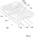
- the textile device 100 comprises a flexible textile basic structure 110 composed of textile threads 101 with a surface 111 and a lower surface 112, the basic structure 110 with at least one electrically conductive heating thread 120 connected to a first voltage source and with an electrically conductive and a second voltage source connected sensor thread 130 is provided for sensing a temperature of the basic structure 110.
- a control circuit electrically connected to at least one sensor thread 130 is provided in order to control the intensity of a current flow through the heating threads 120 in response to a measured temperature or humidity by one for each measured actual value enter predetermined target value of heat in the basic structure 110.
- the heating filament 120 and the sensor filament 130 are attached in the region of the same surface 111 of the basic structure 110.
- the control circuit is designed to control the intensity of a current flow through the heating filaments 120 in response to a measured temperature or humidity in order to enter a predetermined setpoint value of heat in the basic structure 110 for each measured actual value in order to ensure that the basic structure 110 always has the same predetermined value Bring temperature.
- the control circuit is also designed to control an intensity of the current flowing through the at least one filament 120 in the case of a sensor thread 130 which has a non-linear measurement curve in the case of a linear temperature increase or linear increase in humidity, in order to generate such a heat input into the basic structure 110 that the temperature of the base structure 110 is always constant regardless of the measured temperature or humidity.
- a heating filament 120 of the textile device 100 according to the invention is formed by a carbon filament.
- a temperature sensor thread 130 is formed by a PTC thermistor with a positive temperature coefficient (PTC conductor).
- the basic structure 110 is formed from a fabric and both the heating filament 120 and the sensor thread 130 are woven into the basic structure 110.
- a filament 120 introduced into the basic structure 110 is designed to run in a meandering manner in order to cover the largest possible surface area of the basic structure 110.
- the heating filament 120 introduced into the basic structure 110 forms a closed loop with two adjacent ends 121, 122, a first end 121 having to be connected to a first pole of the first voltage source and a second end 122 having to be connected to the second pole of the first voltage source ,
- the loop of the filament is in the Figure 1 Embodiment shown running introduced into the base structure 110 in a meandering manner in such a way that a first loop part 123, which leads from the first end 121 of the heating filament 120 to a reversal point 125 of the heating filament 120, is placed parallel at a predetermined distance from a second loop part 124 which extends from the reversal point 125 leads to the second end 122 of the filament 120.
- the loop of the heating filament 120 is introduced into the basic structure 110 in a partially meandering manner in such a way that a first loop part 123 ', which leads from the first end 121 of the heating filament 120 to a reversal point 125 of the heating filament 120, meanders in parallel at a predetermined distance the loop shape of the meandering sensor thread 130 is introduced into the basic structure 110, and a second loop part 124 ', which is from the point of reversal 125 extends to the second end 122 of the heating filament 120, is introduced into the basic structure 110 in a straight line.
Landscapes
- Engineering & Computer Science (AREA)
- Textile Engineering (AREA)
- Treatment Of Fiber Materials (AREA)
- Investigating Or Analyzing Materials Using Thermal Means (AREA)
- Control Of Resistance Heating (AREA)
Applications Claiming Priority (1)
| Application Number | Priority Date | Filing Date | Title |
|---|---|---|---|
| DE102018116474.2A DE102018116474A1 (de) | 2018-07-06 | 2018-07-06 | Beheizbare Textil-Vorrichtung |
Publications (2)
| Publication Number | Publication Date |
|---|---|
| EP3592104A1 true EP3592104A1 (fr) | 2020-01-08 |
| EP3592104B1 EP3592104B1 (fr) | 2022-03-16 |
Family
ID=67180582
Family Applications (1)
| Application Number | Title | Priority Date | Filing Date |
|---|---|---|---|
| EP19184289.7A Not-in-force EP3592104B1 (fr) | 2018-07-06 | 2019-07-04 | Dispositif textile chauffable |
Country Status (3)
| Country | Link |
|---|---|
| US (1) | US20200015326A1 (fr) |
| EP (1) | EP3592104B1 (fr) |
| DE (1) | DE102018116474A1 (fr) |
Cited By (1)
| Publication number | Priority date | Publication date | Assignee | Title |
|---|---|---|---|---|
| FR3099334A1 (fr) * | 2019-07-22 | 2021-01-29 | Valeo Systemes Thermiques | Structure chauffante pour véhicule automobile |
Families Citing this family (3)
| Publication number | Priority date | Publication date | Assignee | Title |
|---|---|---|---|---|
| US11267380B2 (en) | 2018-08-03 | 2022-03-08 | Illinois Tool Works Inc. | Suspension fabric seat heating system |
| FR3116408B1 (fr) * | 2020-11-19 | 2023-10-27 | Valeo Systemes Thermiques | Structure chauffante pour véhicule automobile |
| US11856661B1 (en) * | 2021-02-24 | 2023-12-26 | Automated Assembly Corporation | Flexible heating element |
Citations (2)
| Publication number | Priority date | Publication date | Assignee | Title |
|---|---|---|---|---|
| US4149066A (en) * | 1975-11-20 | 1979-04-10 | Akitoshi Niibe | Temperature controlled flexible electric heating panel |
| US20040004070A1 (en) * | 2002-07-08 | 2004-01-08 | Sunbeam Products, Inc. | Temperature sensor for a warming blanket |
Family Cites Families (6)
| Publication number | Priority date | Publication date | Assignee | Title |
|---|---|---|---|---|
| US5861610A (en) * | 1997-03-21 | 1999-01-19 | Micro Weiss Electronics | Heater wire with integral sensor wire and improved controller for same |
| WO2005089019A2 (fr) * | 2004-03-08 | 2005-09-22 | W.E.T. Automotive Systems Ag | Element de chauffage plat |
| KR20120031847A (ko) * | 2010-09-27 | 2012-04-04 | 주식회사 시몬스침대 | 온열 부위의 조절이 가능한 침대용 발열장치 |
| DE102013102228A1 (de) * | 2013-03-06 | 2014-09-25 | Kunert Fashion Gmbh & Co. Kg | Textiles Inkontinenzprodukt |
| DE102015100449A1 (de) * | 2014-02-04 | 2015-08-06 | HeizTex GmbH | Flächenhaftes, elektrisches Widerstandsheiznetz |
| DE102015004004A1 (de) * | 2015-03-30 | 2016-10-06 | I.G. Bauerhin Gmbh | Heizelement für benutzerberührbare Flächen |
-
2018
- 2018-07-06 DE DE102018116474.2A patent/DE102018116474A1/de not_active Ceased
-
2019
- 2019-07-04 EP EP19184289.7A patent/EP3592104B1/fr not_active Not-in-force
- 2019-07-08 US US16/504,708 patent/US20200015326A1/en not_active Abandoned
Patent Citations (2)
| Publication number | Priority date | Publication date | Assignee | Title |
|---|---|---|---|---|
| US4149066A (en) * | 1975-11-20 | 1979-04-10 | Akitoshi Niibe | Temperature controlled flexible electric heating panel |
| US20040004070A1 (en) * | 2002-07-08 | 2004-01-08 | Sunbeam Products, Inc. | Temperature sensor for a warming blanket |
Non-Patent Citations (1)
| Title |
|---|
| CHERENACK KUNIGUNDE ET AL: "Smart textiles: Challenges and opportunities", JOURNAL OF APPLIED PHYSICS, AMERICAN INSTITUTE OF PHYSICS, US, vol. 112, no. 9, 1 November 2012 (2012-11-01), pages 91301 - 91301, XP012167768, ISSN: 0021-8979, [retrieved on 20121107], DOI: 10.1063/1.4742728 * |
Cited By (1)
| Publication number | Priority date | Publication date | Assignee | Title |
|---|---|---|---|---|
| FR3099334A1 (fr) * | 2019-07-22 | 2021-01-29 | Valeo Systemes Thermiques | Structure chauffante pour véhicule automobile |
Also Published As
| Publication number | Publication date |
|---|---|
| DE102018116474A1 (de) | 2020-01-09 |
| US20200015326A1 (en) | 2020-01-09 |
| EP3592104B1 (fr) | 2022-03-16 |
Similar Documents
| Publication | Publication Date | Title |
|---|---|---|
| EP3592104A1 (fr) | Dispositif textile chauffable | |
| DE958945C (de) | Biegsames, drahtartiges, temperaturempfindliches Element mit einer Vorrichtung zur fortlaufenden UEberwachung oder Regelung eines Stromkreises | |
| DE102005050459B3 (de) | Flexibles Flächenheizelement, insbesondere für Sitzheizungen, und Verfahren zur Herstellung eines flexiblen Heizelements | |
| DE1291031B (de) | Elektrisches Widerstands-Heizband | |
| DE102014103978A1 (de) | Sensorgarn | |
| DE1540765C3 (de) | Elektrische Heizdecke oder Heizkissen | |
| DE102019130746A1 (de) | Kombinierte kapazitive Sensor- und Heizvorrichtung für eine Lenkeingabevorrichtung, Lenkeingabevorrichtung und Verfahren zum Betrieb einer Lenkeingabevorrichtung | |
| EP3197241A1 (fr) | Dispositif de chauffage et procede de mesure des temperatures sur un dispositif de chauffage | |
| DE2032235C3 (de) | Elektrisches Widerstandserhitzungskabel | |
| EP1601235B1 (fr) | Dispositif de surveillance pour éléments chauffants flexibles. | |
| DE19816816A1 (de) | Elektrisch erwärmbares Flächenheizelement | |
| DE102013216256A1 (de) | Temperaturfühleinrichtung und Temperaturregler | |
| DE69732406T2 (de) | Herstellungsverfahren für Flächenheizkörper und damit hergestellte Flächenheizkörper | |
| DE4311947A1 (de) | Meßelektrode für Leckortungssysteme | |
| DE102006020113A1 (de) | Sensor | |
| DE102018210036A1 (de) | Textiles Element, sowie Dichtung | |
| DE102018102471B3 (de) | Vorrichtung und Verfahren zur Messung einer Temperaturverteilung auf einer Oberfläche | |
| EP3016475B1 (fr) | Dispositif dote de surfaces pouvant etre chauffees pour la dissipation homogene de chaleur | |
| DE102022004262A1 (de) | Sensorvorrichtung | |
| DE1910026C3 (de) | Elektrische Flächenheizeinricmung | |
| WO2015117595A1 (fr) | Résistance chauffante électrique en forme de treillis plan | |
| DE3708945A1 (de) | Inhaliervorrichtung | |
| DE202015002364U1 (de) | Heizelement für benutzerberührbare Flächen | |
| WO1988000626A1 (fr) | Glissiere de contact pour arrets de fils electriques | |
| DE1808022B2 (de) | Biegsames elektrisches flaechenheizelement |
Legal Events
| Date | Code | Title | Description |
|---|---|---|---|
| PUAI | Public reference made under article 153(3) epc to a published international application that has entered the european phase |
Free format text: ORIGINAL CODE: 0009012 |
|
| STAA | Information on the status of an ep patent application or granted ep patent |
Free format text: STATUS: THE APPLICATION HAS BEEN PUBLISHED |
|
| AK | Designated contracting states |
Kind code of ref document: A1 Designated state(s): AL AT BE BG CH CY CZ DE DK EE ES FI FR GB GR HR HU IE IS IT LI LT LU LV MC MK MT NL NO PL PT RO RS SE SI SK SM TR |
|
| AX | Request for extension of the european patent |
Extension state: BA ME |
|
| STAA | Information on the status of an ep patent application or granted ep patent |
Free format text: STATUS: REQUEST FOR EXAMINATION WAS MADE |
|
| 17P | Request for examination filed |
Effective date: 20200416 |
|
| STAA | Information on the status of an ep patent application or granted ep patent |
Free format text: STATUS: EXAMINATION IS IN PROGRESS |
|
| 17Q | First examination report despatched |
Effective date: 20210520 |
|
| GRAP | Despatch of communication of intention to grant a patent |
Free format text: ORIGINAL CODE: EPIDOSNIGR1 |
|
| STAA | Information on the status of an ep patent application or granted ep patent |
Free format text: STATUS: GRANT OF PATENT IS INTENDED |
|
| INTG | Intention to grant announced |
Effective date: 20211123 |
|
| GRAS | Grant fee paid |
Free format text: ORIGINAL CODE: EPIDOSNIGR3 |
|
| GRAA | (expected) grant |
Free format text: ORIGINAL CODE: 0009210 |
|
| STAA | Information on the status of an ep patent application or granted ep patent |
Free format text: STATUS: THE PATENT HAS BEEN GRANTED |
|
| AK | Designated contracting states |
Kind code of ref document: B1 Designated state(s): AL AT BE BG CH CY CZ DE DK EE ES FI FR GB GR HR HU IE IS IT LI LT LU LV MC MK MT NL NO PL PT RO RS SE SI SK SM TR |
|
| REG | Reference to a national code |
Ref country code: GB Ref legal event code: FG4D Free format text: NOT ENGLISH |
|
| REG | Reference to a national code |
Ref country code: CH Ref legal event code: EP |
|
| REG | Reference to a national code |
Ref country code: DE Ref legal event code: R096 Ref document number: 502019003703 Country of ref document: DE |
|
| REG | Reference to a national code |
Ref country code: IE Ref legal event code: FG4D Free format text: LANGUAGE OF EP DOCUMENT: GERMAN |
|
| REG | Reference to a national code |
Ref country code: AT Ref legal event code: REF Ref document number: 1476785 Country of ref document: AT Kind code of ref document: T Effective date: 20220415 |
|
| REG | Reference to a national code |
Ref country code: LT Ref legal event code: MG9D |
|
| REG | Reference to a national code |
Ref country code: NL Ref legal event code: MP Effective date: 20220316 |
|
| PG25 | Lapsed in a contracting state [announced via postgrant information from national office to epo] |
Ref country code: SE Free format text: LAPSE BECAUSE OF FAILURE TO SUBMIT A TRANSLATION OF THE DESCRIPTION OR TO PAY THE FEE WITHIN THE PRESCRIBED TIME-LIMIT Effective date: 20220316 Ref country code: RS Free format text: LAPSE BECAUSE OF FAILURE TO SUBMIT A TRANSLATION OF THE DESCRIPTION OR TO PAY THE FEE WITHIN THE PRESCRIBED TIME-LIMIT Effective date: 20220316 Ref country code: NO Free format text: LAPSE BECAUSE OF FAILURE TO SUBMIT A TRANSLATION OF THE DESCRIPTION OR TO PAY THE FEE WITHIN THE PRESCRIBED TIME-LIMIT Effective date: 20220616 Ref country code: LT Free format text: LAPSE BECAUSE OF FAILURE TO SUBMIT A TRANSLATION OF THE DESCRIPTION OR TO PAY THE FEE WITHIN THE PRESCRIBED TIME-LIMIT Effective date: 20220316 Ref country code: HR Free format text: LAPSE BECAUSE OF FAILURE TO SUBMIT A TRANSLATION OF THE DESCRIPTION OR TO PAY THE FEE WITHIN THE PRESCRIBED TIME-LIMIT Effective date: 20220316 Ref country code: BG Free format text: LAPSE BECAUSE OF FAILURE TO SUBMIT A TRANSLATION OF THE DESCRIPTION OR TO PAY THE FEE WITHIN THE PRESCRIBED TIME-LIMIT Effective date: 20220616 |
|
| PG25 | Lapsed in a contracting state [announced via postgrant information from national office to epo] |
Ref country code: LV Free format text: LAPSE BECAUSE OF FAILURE TO SUBMIT A TRANSLATION OF THE DESCRIPTION OR TO PAY THE FEE WITHIN THE PRESCRIBED TIME-LIMIT Effective date: 20220316 Ref country code: GR Free format text: LAPSE BECAUSE OF FAILURE TO SUBMIT A TRANSLATION OF THE DESCRIPTION OR TO PAY THE FEE WITHIN THE PRESCRIBED TIME-LIMIT Effective date: 20220617 Ref country code: FI Free format text: LAPSE BECAUSE OF FAILURE TO SUBMIT A TRANSLATION OF THE DESCRIPTION OR TO PAY THE FEE WITHIN THE PRESCRIBED TIME-LIMIT Effective date: 20220316 |
|
| PG25 | Lapsed in a contracting state [announced via postgrant information from national office to epo] |
Ref country code: NL Free format text: LAPSE BECAUSE OF FAILURE TO SUBMIT A TRANSLATION OF THE DESCRIPTION OR TO PAY THE FEE WITHIN THE PRESCRIBED TIME-LIMIT Effective date: 20220316 |
|
| PG25 | Lapsed in a contracting state [announced via postgrant information from national office to epo] |
Ref country code: SM Free format text: LAPSE BECAUSE OF FAILURE TO SUBMIT A TRANSLATION OF THE DESCRIPTION OR TO PAY THE FEE WITHIN THE PRESCRIBED TIME-LIMIT Effective date: 20220316 Ref country code: SK Free format text: LAPSE BECAUSE OF FAILURE TO SUBMIT A TRANSLATION OF THE DESCRIPTION OR TO PAY THE FEE WITHIN THE PRESCRIBED TIME-LIMIT Effective date: 20220316 Ref country code: RO Free format text: LAPSE BECAUSE OF FAILURE TO SUBMIT A TRANSLATION OF THE DESCRIPTION OR TO PAY THE FEE WITHIN THE PRESCRIBED TIME-LIMIT Effective date: 20220316 Ref country code: PT Free format text: LAPSE BECAUSE OF FAILURE TO SUBMIT A TRANSLATION OF THE DESCRIPTION OR TO PAY THE FEE WITHIN THE PRESCRIBED TIME-LIMIT Effective date: 20220718 Ref country code: ES Free format text: LAPSE BECAUSE OF FAILURE TO SUBMIT A TRANSLATION OF THE DESCRIPTION OR TO PAY THE FEE WITHIN THE PRESCRIBED TIME-LIMIT Effective date: 20220316 Ref country code: EE Free format text: LAPSE BECAUSE OF FAILURE TO SUBMIT A TRANSLATION OF THE DESCRIPTION OR TO PAY THE FEE WITHIN THE PRESCRIBED TIME-LIMIT Effective date: 20220316 Ref country code: CZ Free format text: LAPSE BECAUSE OF FAILURE TO SUBMIT A TRANSLATION OF THE DESCRIPTION OR TO PAY THE FEE WITHIN THE PRESCRIBED TIME-LIMIT Effective date: 20220316 |
|
| PG25 | Lapsed in a contracting state [announced via postgrant information from national office to epo] |
Ref country code: PL Free format text: LAPSE BECAUSE OF FAILURE TO SUBMIT A TRANSLATION OF THE DESCRIPTION OR TO PAY THE FEE WITHIN THE PRESCRIBED TIME-LIMIT Effective date: 20220316 Ref country code: IS Free format text: LAPSE BECAUSE OF FAILURE TO SUBMIT A TRANSLATION OF THE DESCRIPTION OR TO PAY THE FEE WITHIN THE PRESCRIBED TIME-LIMIT Effective date: 20220716 Ref country code: AL Free format text: LAPSE BECAUSE OF FAILURE TO SUBMIT A TRANSLATION OF THE DESCRIPTION OR TO PAY THE FEE WITHIN THE PRESCRIBED TIME-LIMIT Effective date: 20220316 |
|
| REG | Reference to a national code |
Ref country code: DE Ref legal event code: R097 Ref document number: 502019003703 Country of ref document: DE |
|
| PLBE | No opposition filed within time limit |
Free format text: ORIGINAL CODE: 0009261 |
|
| STAA | Information on the status of an ep patent application or granted ep patent |
Free format text: STATUS: NO OPPOSITION FILED WITHIN TIME LIMIT |
|
| PG25 | Lapsed in a contracting state [announced via postgrant information from national office to epo] |
Ref country code: DK Free format text: LAPSE BECAUSE OF FAILURE TO SUBMIT A TRANSLATION OF THE DESCRIPTION OR TO PAY THE FEE WITHIN THE PRESCRIBED TIME-LIMIT Effective date: 20220316 |
|
| REG | Reference to a national code |
Ref country code: DE Ref legal event code: R119 Ref document number: 502019003703 Country of ref document: DE |
|
| 26N | No opposition filed |
Effective date: 20221219 |
|
| PG25 | Lapsed in a contracting state [announced via postgrant information from national office to epo] |
Ref country code: SI Free format text: LAPSE BECAUSE OF FAILURE TO SUBMIT A TRANSLATION OF THE DESCRIPTION OR TO PAY THE FEE WITHIN THE PRESCRIBED TIME-LIMIT Effective date: 20220316 Ref country code: MC Free format text: LAPSE BECAUSE OF FAILURE TO SUBMIT A TRANSLATION OF THE DESCRIPTION OR TO PAY THE FEE WITHIN THE PRESCRIBED TIME-LIMIT Effective date: 20220316 |
|
| REG | Reference to a national code |
Ref country code: CH Ref legal event code: PL |
|
| REG | Reference to a national code |
Ref country code: BE Ref legal event code: MM Effective date: 20220731 |
|
| PG25 | Lapsed in a contracting state [announced via postgrant information from national office to epo] |
Ref country code: LU Free format text: LAPSE BECAUSE OF NON-PAYMENT OF DUE FEES Effective date: 20220704 Ref country code: LI Free format text: LAPSE BECAUSE OF NON-PAYMENT OF DUE FEES Effective date: 20220731 Ref country code: FR Free format text: LAPSE BECAUSE OF NON-PAYMENT OF DUE FEES Effective date: 20220731 Ref country code: CH Free format text: LAPSE BECAUSE OF NON-PAYMENT OF DUE FEES Effective date: 20220731 |
|
| PG25 | Lapsed in a contracting state [announced via postgrant information from national office to epo] |
Ref country code: DE Free format text: LAPSE BECAUSE OF NON-PAYMENT OF DUE FEES Effective date: 20230201 Ref country code: BE Free format text: LAPSE BECAUSE OF NON-PAYMENT OF DUE FEES Effective date: 20220731 |
|
| PG25 | Lapsed in a contracting state [announced via postgrant information from national office to epo] |
Ref country code: IT Free format text: LAPSE BECAUSE OF FAILURE TO SUBMIT A TRANSLATION OF THE DESCRIPTION OR TO PAY THE FEE WITHIN THE PRESCRIBED TIME-LIMIT Effective date: 20220316 Ref country code: IE Free format text: LAPSE BECAUSE OF NON-PAYMENT OF DUE FEES Effective date: 20220704 |
|
| GBPC | Gb: european patent ceased through non-payment of renewal fee |
Effective date: 20230704 |
|
| PG25 | Lapsed in a contracting state [announced via postgrant information from national office to epo] |
Ref country code: HU Free format text: LAPSE BECAUSE OF FAILURE TO SUBMIT A TRANSLATION OF THE DESCRIPTION OR TO PAY THE FEE WITHIN THE PRESCRIBED TIME-LIMIT; INVALID AB INITIO Effective date: 20190704 |
|
| PG25 | Lapsed in a contracting state [announced via postgrant information from national office to epo] |
Ref country code: MK Free format text: LAPSE BECAUSE OF FAILURE TO SUBMIT A TRANSLATION OF THE DESCRIPTION OR TO PAY THE FEE WITHIN THE PRESCRIBED TIME-LIMIT Effective date: 20220316 Ref country code: CY Free format text: LAPSE BECAUSE OF FAILURE TO SUBMIT A TRANSLATION OF THE DESCRIPTION OR TO PAY THE FEE WITHIN THE PRESCRIBED TIME-LIMIT Effective date: 20220316 Ref country code: GB Free format text: LAPSE BECAUSE OF NON-PAYMENT OF DUE FEES Effective date: 20230704 |
|
| PG25 | Lapsed in a contracting state [announced via postgrant information from national office to epo] |
Ref country code: MT Free format text: LAPSE BECAUSE OF FAILURE TO SUBMIT A TRANSLATION OF THE DESCRIPTION OR TO PAY THE FEE WITHIN THE PRESCRIBED TIME-LIMIT Effective date: 20220316 |
|
| REG | Reference to a national code |
Ref country code: AT Ref legal event code: MM01 Ref document number: 1476785 Country of ref document: AT Kind code of ref document: T Effective date: 20240704 |
|
| PG25 | Lapsed in a contracting state [announced via postgrant information from national office to epo] |
Ref country code: AT Free format text: LAPSE BECAUSE OF NON-PAYMENT OF DUE FEES Effective date: 20240704 |
|
| PG25 | Lapsed in a contracting state [announced via postgrant information from national office to epo] |
Ref country code: TR Free format text: LAPSE BECAUSE OF FAILURE TO SUBMIT A TRANSLATION OF THE DESCRIPTION OR TO PAY THE FEE WITHIN THE PRESCRIBED TIME-LIMIT Effective date: 20220316 |
|
| PGFP | Annual fee paid to national office [announced via postgrant information from national office to epo] |
Ref country code: AT Payment date: 20260410 Year of fee payment: 5 |