EP3593002B1 - Dispositif d'embrayage et module hybride - Google Patents
Dispositif d'embrayage et module hybride Download PDFInfo
- Publication number
- EP3593002B1 EP3593002B1 EP18711220.6A EP18711220A EP3593002B1 EP 3593002 B1 EP3593002 B1 EP 3593002B1 EP 18711220 A EP18711220 A EP 18711220A EP 3593002 B1 EP3593002 B1 EP 3593002B1
- Authority
- EP
- European Patent Office
- Prior art keywords
- clutch
- clutch device
- pressure
- ramp
- ramp element
- Prior art date
- Legal status (The legal status is an assumption and is not a legal conclusion. Google has not performed a legal analysis and makes no representation as to the accuracy of the status listed.)
- Active
Links
Images
Classifications
-
- B—PERFORMING OPERATIONS; TRANSPORTING
- B60—VEHICLES IN GENERAL
- B60K—ARRANGEMENT OR MOUNTING OF PROPULSION UNITS OR OF TRANSMISSIONS IN VEHICLES; ARRANGEMENT OR MOUNTING OF PLURAL DIVERSE PRIME-MOVERS IN VEHICLES; AUXILIARY DRIVES FOR VEHICLES; INSTRUMENTATION OR DASHBOARDS FOR VEHICLES; ARRANGEMENTS IN CONNECTION WITH COOLING, AIR INTAKE, GAS EXHAUST OR FUEL SUPPLY OF PROPULSION UNITS IN VEHICLES
- B60K6/00—Arrangement or mounting of plural diverse prime-movers for mutual or common propulsion, e.g. hybrid propulsion systems comprising electric motors and internal combustion engines
- B60K6/20—Arrangement or mounting of plural diverse prime-movers for mutual or common propulsion, e.g. hybrid propulsion systems comprising electric motors and internal combustion engines the prime-movers consisting of electric motors and internal combustion engines, e.g. HEVs
- B60K6/22—Arrangement or mounting of plural diverse prime-movers for mutual or common propulsion, e.g. hybrid propulsion systems comprising electric motors and internal combustion engines the prime-movers consisting of electric motors and internal combustion engines, e.g. HEVs characterised by apparatus, components or means specially adapted for HEVs
- B60K6/38—Arrangement or mounting of plural diverse prime-movers for mutual or common propulsion, e.g. hybrid propulsion systems comprising electric motors and internal combustion engines the prime-movers consisting of electric motors and internal combustion engines, e.g. HEVs characterised by apparatus, components or means specially adapted for HEVs characterised by the driveline clutches
- B60K6/387—Actuated clutches, i.e. clutches engaged or disengaged by electric, hydraulic or mechanical actuating means
-
- F—MECHANICAL ENGINEERING; LIGHTING; HEATING; WEAPONS; BLASTING
- F16—ENGINEERING ELEMENTS AND UNITS; GENERAL MEASURES FOR PRODUCING AND MAINTAINING EFFECTIVE FUNCTIONING OF MACHINES OR INSTALLATIONS; THERMAL INSULATION IN GENERAL
- F16D—COUPLINGS FOR TRANSMITTING ROTATION; CLUTCHES; BRAKES
- F16D13/00—Friction clutches
- F16D13/22—Friction clutches with axially-movable clutching members
- F16D13/38—Friction clutches with axially-movable clutching members with flat clutching surfaces, e.g. discs
- F16D13/52—Clutches with multiple lamellae ; Clutches in which three or more axially moveable members are fixed alternately to the shafts to be coupled and are pressed from one side towards an axially-located member
- F16D13/54—Clutches with multiple lamellae ; Clutches in which three or more axially moveable members are fixed alternately to the shafts to be coupled and are pressed from one side towards an axially-located member with means for increasing the effective force between the actuating sleeve or equivalent member and the pressure member
-
- F—MECHANICAL ENGINEERING; LIGHTING; HEATING; WEAPONS; BLASTING
- F16—ENGINEERING ELEMENTS AND UNITS; GENERAL MEASURES FOR PRODUCING AND MAINTAINING EFFECTIVE FUNCTIONING OF MACHINES OR INSTALLATIONS; THERMAL INSULATION IN GENERAL
- F16D—COUPLINGS FOR TRANSMITTING ROTATION; CLUTCHES; BRAKES
- F16D23/00—Details of mechanically-actuated clutches not specific for one distinct type
- F16D23/12—Mechanical clutch-actuating mechanisms arranged outside the clutch as such
-
- F—MECHANICAL ENGINEERING; LIGHTING; HEATING; WEAPONS; BLASTING
- F16—ENGINEERING ELEMENTS AND UNITS; GENERAL MEASURES FOR PRODUCING AND MAINTAINING EFFECTIVE FUNCTIONING OF MACHINES OR INSTALLATIONS; THERMAL INSULATION IN GENERAL
- F16D—COUPLINGS FOR TRANSMITTING ROTATION; CLUTCHES; BRAKES
- F16D25/00—Fluid-actuated clutches
- F16D25/08—Fluid-actuated clutches with fluid-actuated member not rotating with a clutching member
- F16D25/082—Fluid-actuated clutches with fluid-actuated member not rotating with a clutching member the line of action of the fluid-actuated members co-inciding with the axis of rotation
-
- F—MECHANICAL ENGINEERING; LIGHTING; HEATING; WEAPONS; BLASTING
- F16—ENGINEERING ELEMENTS AND UNITS; GENERAL MEASURES FOR PRODUCING AND MAINTAINING EFFECTIVE FUNCTIONING OF MACHINES OR INSTALLATIONS; THERMAL INSULATION IN GENERAL
- F16D—COUPLINGS FOR TRANSMITTING ROTATION; CLUTCHES; BRAKES
- F16D23/00—Details of mechanically-actuated clutches not specific for one distinct type
- F16D23/12—Mechanical clutch-actuating mechanisms arranged outside the clutch as such
- F16D2023/123—Clutch actuation by cams, ramps or ball-screw mechanisms
-
- Y—GENERAL TAGGING OF NEW TECHNOLOGICAL DEVELOPMENTS; GENERAL TAGGING OF CROSS-SECTIONAL TECHNOLOGIES SPANNING OVER SEVERAL SECTIONS OF THE IPC; TECHNICAL SUBJECTS COVERED BY FORMER USPC CROSS-REFERENCE ART COLLECTIONS [XRACs] AND DIGESTS
- Y02—TECHNOLOGIES OR APPLICATIONS FOR MITIGATION OR ADAPTATION AGAINST CLIMATE CHANGE
- Y02T—CLIMATE CHANGE MITIGATION TECHNOLOGIES RELATED TO TRANSPORTATION
- Y02T10/00—Road transport of goods or passengers
- Y02T10/60—Other road transportation technologies with climate change mitigation effect
- Y02T10/62—Hybrid vehicles
Definitions
- the invention relates to a clutch device and a hybrid module with the clutch device according to the invention.
- the clutch device includes a main clutch with a friction pack and a displaceable pressure device for applying a contact pressure to the friction pack. Furthermore, the clutch device includes a ramp system for shifting the pressure device.
- clutch devices are used, with which the power provided by the combustion unit and / or the power provided by the electric machine on a Drive train is transferrable.
- clutch devices are often equipped with a pilot clutch and a main clutch. By actuating the pilot clutch, a moment can be generated which is used to close or open the main clutch.
- a coupling device is intended to separate the combustion unit from the drive train with as little loss as possible when the electric machine is in operation. It should be possible to close the clutch when the combustion unit is in operation. The actuation of the clutch device should be possible with a minimum of energy. Please refer WO 2016/165701 and US2014 353107 .
- a separating clutch for a hybrid drive With the separating clutch, an internal combustion engine of a vehicle can be separated from an electric machine and a transmission input shaft of a vehicle transmission or connected thereto.
- the electric machine can be used as a starter for starting the internal combustion engine.
- the separating clutch is partially closed by an actuator.
- a planetary gear, a ramp system and an eddy current brake are used to actuate the separating clutch.
- a Freewheel used as a pilot control element to generate a contact pressure with which the disk pack of the clutch is clamped. This freewheel enables the clutch to close automatically, essentially without supplying additional energy. Freewheeling means that the internal combustion engine cannot reach a higher speed than the electric machine or the drive train equipped with it.
- clutch devices that are to be arranged in hybrid modules are, of course, high performance with regard to the torque to be transmitted. Furthermore, in particular when starting the combustion unit using the electric machine, it is required to be able to control the torque to be transmitted from the electric machine to the combustion unit.
- the invention is therefore based on the object of providing a clutch device and a hybrid module with which a torque applied by a combustion unit can be transmitted to an output or to a drive train and also in a reliable and energy-efficient manner is transferrable in the reverse manner, and which ensure a controllable starting process of the combustion unit by means of the electric machine with a small structural volume and moderate production costs.
- the clutch device comprises a main clutch, which can be a dry or wet clutch in a single-plate or multi-plate design.
- This main clutch has a friction pack and a displaceable pressure device, preferably in the form of a pressure pot, for realizing a contact pressure force on the friction pack.
- the clutch device includes a ramp system for shifting the pressure device for the purpose of applying force to the friction pack.
- the clutch device also has a pilot clutch for the purpose of torque transmission to the ramp system.
- the pilot clutch includes a counter-plate and an actuating device for shifting the counter-plate. The pilot clutch can be opened and closed by moving the counter plate.
- the counter-plate can be displaced to such an extent that it can apply a force to the pressure device and in this way can move the pressure device.
- the clutch device has an inner cage and an outer cage, with the friction assembly being mechanically connected to the inner cage and the outer cage.
- the ramp system comprises a ramp element arranged on the inner cage and a ramp element that can be rotated relative thereto, the rotatable ramp element and the pilot clutch being mechanically connected to the inner cage and the outer cage when the pilot clutch is closed.
- the one on the inner basket arranged ramp element is connected to the inner basket by means of a freewheel, which blocks a rotational movement of the ramp element in relation to the inner basket in one direction of rotation and opposite to this direction of rotation are free.
- the friction clutch is set up to transmit torque from an output shaft to a consumer and vice versa.
- the pressure device applies a contact pressure force to the friction pack in order to compress the lamellae of the friction pack and thus to close the main clutch so that it can transmit torque from a combustion unit to a drive train.
- the pressure device is mechanically coupled to the ramp system.
- the torque generated by a combustion engine is transmitted to the ramp system by means of the pilot clutch.
- the pilot clutch is opened or closed by the movement of the counterplate, so that it can be controlled in such a way as to whether or not a torque is transmitted from a combustion unit to the ramp system via the pilot clutch.
- the second function of the counter-plate is to exert a force directly and preferably immediately on the pressure device when the counter-plate is displaced, so that the main clutch can also be closed in this way.
- the mentioned freewheel means a clutch device that only acts in one direction of rotation, which can transfer the rotary movement of the ramp element to the inner basket, but cannot transfer any rotary movement or torque from the inner basket to the connected ramp element in the same direction of rotation.
- the direction of rotation in which the freewheel can transmit the torque or the rotary movement of the ramp element to the inner basket is the direction of rotation of a combustion unit to be connected to the clutch device or an electric drive unit to be connected to the inner basket, such as an electric motor.
- the arranged on the inner basket ramp element and the rotatable ramp element are configured such that the rotatable
- Ramp element away from or approaching the ramp element arranged on the inner basket during a rotational movement due to inclined ramps.
- the configuration of the clutch device with the freewheel enables traction operation to be implemented in a simple manner in which the connected combustion unit applies a torque to the outer cage of the main clutch, and this rotational movement or this torque is transmitted to the ramp system when the pilot control clutch is actuated , which moves the pressure pot of the main clutch and thus closes the main clutch and thus connects the inner cage of the main clutch with the outer cage of the main clutch in a non-positive manner. Due to the locking effect of the freewheel, the rotatable ramp element can be rotated in relation to the ramp element connected to the inner cage, so that the two ramp elements are axially removed.
- a further advantage of the clutch device according to the invention is that with little technical means and with only a small overall volume, a force can be metered onto the pressure device by means of the counter-plate, so that a torque which, for. B. is generated by an electric machine, can be introduced into the main clutch, so that the combustion unit by means of the electric machine provided torque can be started.
- the technical means for realizing this starting process namely the counter-plate and the pressure device, thus have a dual function, namely the transmission of torque from the combustion unit to a drive train and the described function of conducting torque from the electric machine to the combustion unit, e.g. B. to start this.
- fewer components and also less installation space are required in comparison to conventional embodiments in hybrid modules.
- the coupling device is preferably implemented in such a way that the force that can be applied by the counter-plate to the pressure device can be exerted directly on the pressure device. This means that in this configuration of the coupling device, the counter-plate can be pressed against the pressure device in order to displace it.
- any thin intermediate layers are present between the backing plate and the printing device, such as e.g. B. layers of paint or other coatings.
- the pilot clutch has spring devices, in particular leaf springs.
- the forces acting in the pilot clutch can be defined with these spring devices.
- the actuating device for moving the counter-plate preferably comprises a plurality of pressure pins which act on the counter-plate.
- the counter plate can be moved with the pressure pins by applying tensile and compressive forces.
- the actuating device includes at least one mechanical releaser, which can be operated electromechanically or hydraulically or pneumatically.
- the movement of the pressure pins is advantageously realized by at least one hydraulic drive, which is mechanically coupled to the pressure pins.
- a friction disc of the pilot clutch is constantly connected to the outer basket. However, only when the pilot clutch is closed is the pilot clutch fully connected to the outer basket.
- Rolling bodies in particular balls, can be arranged between the two ramp elements.
- the ramp surfaces mentioned can then form running surfaces for the rolling bodies.
- the ramp surfaces are preferably arranged on the periphery of the ramp elements.
- the inner cage is supported on at least one support bearing parallel to the axis of rotation of the clutch device.
- This support bearing preferably forms a shoulder so that it is suitable for absorbing the axial forces.
- an axial bearing is advantageously arranged between the ramp system and in particular between the rotatable ramp element and the pressure device. This axial bearing also serves to absorb forces running axially, ie parallel to the axis of rotation.
- the pressure pins of the actuating device are preferably slidably mounted in the rotatable ramp element.
- the clutch device thus made available can function in particular as a separating clutch for a hybrid drive of a hybrid vehicle.
- the pilot clutch used can be actuated sequentially by an actuator in the form of pressure pins and preferably a hydraulic device. As a result, the pilot clutch can be opened in order to separate the combustion unit from an electric machine.
- the ramp system is essentially load-free so that the rotatable ramp element can rotate relative to the ramp element arranged on the inner cage and can be displaced axially such that the pressure device operatively connected thereto removes the contact pressure force on the friction pack of the main clutch. This opens the main clutch.
- the actuating device is used again used to apply a compressive force directly to the printing device.
- a hybrid module which has a first drive unit, in particular in the form of an internal combustion engine or a combustion unit, with this first drive unit having an output shaft. Furthermore, the hybrid module comprises a drive train with a second drive unit mechanically coupled thereto, in particular an electric machine.
- the hybrid module includes the clutch device according to the invention, wherein the output shaft of the first drive unit can be releasably connected to the drive train for torque transmission by means of the clutch device.
- the internal combustion engine or the combustion unit, the clutch device, the electric machine and a transmission unit can be arranged in the order mentioned in the hybrid module.
- the hybrid module can also have a torsional vibration damper, in particular a dual-mass flywheel. The torsional vibration damper can have an energy store.
- the combustion unit can be energy-efficiently coupled to the drive train or decoupled from the drive train by the coupling device of the hybrid module according to the invention.
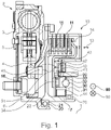
- the hybrid module shown in a sectional view has a dual-mass flywheel 2 which is connected to a centrifugal pendulum 5 .
- the two-mass flywheel 2 and the centrifugal pendulum 5 are connected in a torque-proof manner to an output shaft 6 via a primary side 3 of the two-mass flywheel 2 .
- the output shaft 6 rotates about an axis of rotation 1, which also represents the axis of rotation of the entire hybrid module.
- the secondary side 4 of the dual mass flywheel 2 is mechanically fixed to an outer cage 15 of a main clutch 10 .
- This main clutch 10 comprises a friction pack 11, the lamellae of which are connected to the outer cage 15 and the inner cage 16 in an alternating arrangement.
- the inner basket 16 forms a hub 17 which can also be rotated about the axis of rotation 1 .
- Another component of the main clutch 10 is a pressure device 12, which is designed here as a pressure pot.
- the printing device 12 can be displaced along the displacement direction 13 .
- By corresponding displacement of the pressure device 12, it can be pressed onto the friction assembly 11 with a contact pressure force 14 in order to close the main clutch 10 in this way.
- the inner basket 16 is supported via its hub 17 on a support bearing 20 which forms a shoulder 21 in order to be able to absorb axially acting forces.
- the hybrid module also includes a ramp system 30 which includes a fixed ramp element 31 arranged on the hub 17 by means of a freewheel 70 and a ramp element 32 which can be rotated relative thereto. Between the ramp elements 31, 32 a plurality of balls is arranged.
- the ramp elements 31, 32 are designed with sloping ramp surfaces, not shown separately, on which the balls run. Due to the contact between the sloping ramp surfaces, twisting the rotatable ramp element 32 causes a change in distance in relation to the ramp element 31 arranged on the hub 17 or the inner basket 16.
- the rotatable ramp element 32 is mounted on an axial bearing 34, which moves in the axial direction of the printing device 12 is supported.
- leaf springs 44 are also arranged between the ramp element 31 arranged on the hub 17 or the inner basket 16 and the pressure device 12 that can be displaced via the ramp system 30 .
- a section of the rotatable ramp element 32 forms part of the pilot clutch 40 .
- this pilot control clutch 40 also includes a friction disk 41 and a counterplate 42, which can be displaced parallel to the axis of rotation 1 and can therefore apply such a frictional force to the friction disk 41 between itself and the rotatable ramp element 32 that a torque of of the friction disc 41 can be transferred to the rotatable ramp element 32 and vice versa.
- the actuating device 50 in the form of the pressure pins shown, which can be coupled to a hydraulic, electric or pneumatic drive unit (not shown here), is actuated in such a way that the counter-plate 42 is pulled in the direction of the rotatable ramp element 32 .
- the pressure pins of the actuating device 50 are integrated in a translatory bearing 51 in the rotatable ramp element 32 .
- the pressure device 12 is shifted to the left so that it applies the contact pressure 14 to the friction assembly 11 and thereby the main clutch 10 is closed and the torque is transmitted from the output shaft 6 to the inner cage 16 or the hub 17 .
- the torque path via the pilot clutch 40 is interrupted, so that the ramp system 30 is essentially load-free and the rotatable ramp element 32 moves between the pressure device 12 and that on the hub due to the action of leaf springs 44 17 or the inner basket 16 arranged ramp element 31 shifted back to the right, so that the contact pressure 14 on the friction assembly 11 is canceled.
- the main clutch 10 is opened and the transmission of torque from the output shaft 6 to the inner cage 16 is interrupted.
- a torque introduced into the inner basket 16 by an electric drive is thus introduced into the friction pack 11 of the main clutch 10 and transmitted from this to the dual-mass flywheel 2 and consequently also to the output shaft 6, so that a combustion unit (not shown here) connected to the output shaft 6 is also involved kinetic energy and can be started.
- the actuating device 50 is again actuated, so that the force 45 applied by it is removed and the pressure device 12 is again shifted to the right and the main clutch 10 is opened.
- the torque introduced by the output shaft 6 is used to actuate the ramp system 30 and in this way in turn to shift the pressure device 12 to the left, so that it again applies the contact pressure 14 exerts on the friction pack 11 of the main clutch 10 and thus this main clutch 10 closes, so that the torque made available by the output shaft 6 is transmitted to the inner cage 16 .
- the axial force applied by the actuating device 50 is absorbed by the support bearing 20 , which applies a corresponding, opposing support force 42 to the hub 17 .
- the latter In order to adjust the forces prevailing in the pilot clutch 40 , the latter has leaf springs 33 , in particular between the counterplate 42 and the friction disk 41 .
- a combustion unit can be coupled energy-efficiently to a drive train both when torque is applied and in the driven state.
- the torque transmitted by the pilot clutch 40 is converted by the ramp system 30 into an axial force with which the friction assembly 11 of the main clutch 10 is clamped.
- the axial force generated by the ramp system 30 is absorbed by the hub 17 so that a connected combustion unit is not subjected to an axial load.
- the freewheel 70 arranged between the inner cage 16 and the ramp element 31 enables the rotatable ramp element to be rotated in relation to the ramp element connected to the inner cage, so that the two ramp elements 31, 32 are axially removed.
- a so-called “gliding operation” or a functional state can also be implemented in which the output side or the inner cage 16 of the clutch device rotates faster than the outer cage 15 or a combustion unit connected to it, as is the case, for example, with a Downhill driving a motor vehicle equipped with it can occur.
- a relative rotational movement of the ramp element 31 in relation to the inner cage 16 takes place in the opposite direction of rotation 90 and consequently the freewheel 70 releases the rotationally fixed connection between the inner cage 16 and the ramp element 31, so that the inner cage 16 can rotate faster than the ramp element connected to it 31 and the pilot clutch 40 coupled thereto.
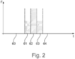
- the actuating device 50 In order to apply the force 45 to be applied by the counter-plate 42 to the pressure device 12, the actuating device 50 must be actuated with a relatively high force and consequently high energy. This state is identified by section 62.
- a torque applied by a combustion unit can be transmitted in a reliable manner to an output or to a drive train and also vice versa, with it being ensured that a combustion unit connected to the clutch device is operated in an energy-efficient manner at a higher speed can be used as a coupled electric machine, so that a controllable starting process of the combustion unit by means of the electric machine and speed-independent operation of the combustion unit can be carried out.
Landscapes
- Engineering & Computer Science (AREA)
- General Engineering & Computer Science (AREA)
- Mechanical Engineering (AREA)
- Chemical & Material Sciences (AREA)
- Combustion & Propulsion (AREA)
- Transportation (AREA)
- Mechanical Operated Clutches (AREA)
- Hybrid Electric Vehicles (AREA)
- Arrangement Of Transmissions (AREA)
Claims (10)
- Dispositif d'embrayage, comprenant un embrayage principal (10) avec un paquet de disques de friction (11) et un dispositif de pression (12) déplaçable pour la génération d'une force de pression (14) sur le paquet de disques de friction (11), ainsi qu'un système de rampe (30) pour le déplacement du dispositif de pression (12),le dispositif d'embrayage comportant également un embrayage pilote (40) pour la transmission d'un couple au système de rampe (30) et l'embrayage pilote (40) comprenant une contre-plaque (42) et un dispositif d'actionnement (50) pour le déplacement de la contre-plaque (42) et l'embrayage pilote (40) pouvant être ouvert et fermé par le déplacement de la contre-plaque (42) et le dispositif de pression (12) pouvant être déplacé par l'exercice d'une force (45) à partir de la contre-plaque (42) sur le dispositif de pression (12) et le dispositif d'embrayage comprenant également un panier intérieur (16) et un panier extérieur (15), le paquet de disques de friction (11) étant relié mécaniquement au panier intérieur (16) et au panier extérieur (15),le système de rampe (30) comprenant un élément de rampe (31) disposé sur le panier intérieur (16) et un élément de rampe (32) pouvant être pivoté par rapport à celui-ci et l'élément de rampe (32) pouvant être pivoté et l'embrayage pilote (40) étant reliés mécaniquement au panier intérieur (16) et au panier extérieur (15) lorsque l'embrayage pilote (40) est fermé,caractérisé en ce que l'élément de rampe (31) disposé sur le panier intérieur (16) est relié au panier intérieur (16) au moyen d'une roue libre (70) qui bloque un mouvement de rotation de l'élément de rampe (32) dans un sens de rotation (80) par rapport au panier intérieur (14) et le libère dans le sens inverse à ce sens de rotation (80).
- Dispositif d'embrayage selon la revendication 1, caractérisé en ce qu' il est agencé de manière à ce que la force (45) susceptible d'être appliquée à partir de la contre-plaque (42) sur le dispositif de pression (12) puisse s'exercer directement sur la dispositif de pression (12).
- Dispositif d'embrayage selon l'une quelconque des revendications précédentes, caractérisé en ce que l'embrayage pilote (40) comporte des dispositifs à ressort, notamment des ressorts à lames (33).
- Dispositif d'embrayage selon l'une quelconque des revendications précédentes, caractérisé en ce que le dispositif d'actionnement (50) comprend une pluralité d'axes de pression qui agissent sur la contre-plaque (42).
- Dispositif d'embrayage selon la revendication 4, caractérisé en ce que le dispositif d'actionnement comprend un entraînement hydraulique qui est couplé mécaniquement aux axes de pression.
- Dispositif d'embrayage selon l'une quelconque des revendications précédentes, caractérisé en ce que la roue libre (70) est disposée radialement entre le panier intérieur (16) et l'élément de rampe (31). D
- Dispositif d'embrayage selon la revendication 6, caractérisé en ce que le panier intérieur (16) prend appui sur un palier d'appui (20) parallèle à l'axe de rotation (1) du dispositif d'embrayage.
- Dispositif d'embrayage selon l'une quelconque des revendications précédentes, caractérisé en ce que le dispositif d'embrayage comporte un palier axial (34) entre le système de rampe (30) et le dispositif de pression (12).
- Dispositif d'embrayage selon l'une quelconque des revendications 4 à 8, caractérisé en ce que les axes de pression du dispositif d'actionnement (50) sont montés de manière déplaçable dans l'élément de rampe (32) pouvant être pivoté.
- Module hybride, comportant une première unité d'entraînement, en particulier un moteur à combustion interne, avec un arbre de sortie (6), une chaîne cinématique avec une seconde unité d'entraînement couplée mécaniquement à celle-ci, en particulier une machine électrique et un dispositif d'embrayage selon l'une quelconque des revendications précédentes, l'arbre de sortie (6) pouvant être relié de manière amovible à la chaîne cinématique au moyen du dispositif d'embrayage pour la transmission d'un couple.
Applications Claiming Priority (2)
| Application Number | Priority Date | Filing Date | Title |
|---|---|---|---|
| DE102017104743.3A DE102017104743A1 (de) | 2017-03-07 | 2017-03-07 | Kupplungseinrichtung und Hybridmodul |
| PCT/DE2018/100163 WO2018162001A1 (fr) | 2017-03-07 | 2018-02-23 | Dispositif d'embrayage et module hybride |
Publications (2)
| Publication Number | Publication Date |
|---|---|
| EP3593002A1 EP3593002A1 (fr) | 2020-01-15 |
| EP3593002B1 true EP3593002B1 (fr) | 2022-07-13 |
Family
ID=61655555
Family Applications (1)
| Application Number | Title | Priority Date | Filing Date |
|---|---|---|---|
| EP18711220.6A Active EP3593002B1 (fr) | 2017-03-07 | 2018-02-23 | Dispositif d'embrayage et module hybride |
Country Status (5)
| Country | Link |
|---|---|
| US (1) | US11518230B2 (fr) |
| EP (1) | EP3593002B1 (fr) |
| CN (1) | CN110382898B (fr) |
| DE (1) | DE102017104743A1 (fr) |
| WO (1) | WO2018162001A1 (fr) |
Families Citing this family (9)
| Publication number | Priority date | Publication date | Assignee | Title |
|---|---|---|---|---|
| DE102019100738B3 (de) | 2019-01-14 | 2020-07-02 | Schaeffler Technologies AG & Co. KG | Elektrische Achsantriebseinheit mit integrierter Bremseinrichtung mit axial beweglichem Bremsscheibenelement |
| DE112020003582T5 (de) * | 2019-07-26 | 2022-04-21 | Denso Corporation | Kupplungsvorrichtung |
| CN114144594A (zh) * | 2019-07-26 | 2022-03-04 | 株式会社电装 | 离合器装置 |
| JP7272216B2 (ja) * | 2019-07-26 | 2023-05-12 | 株式会社デンソー | クラッチ装置 |
| CN114144599A (zh) * | 2019-07-26 | 2022-03-04 | 株式会社电装 | 离合器装置 |
| DE112020003580T5 (de) * | 2019-07-26 | 2022-04-21 | Denso Corporation | Kupplungsvorrichtung |
| CN114144597A (zh) * | 2019-07-26 | 2022-03-04 | 株式会社电装 | 离合器装置 |
| CN114382801A (zh) * | 2020-10-19 | 2022-04-22 | 舍弗勒技术股份两合公司 | 车辆用制动系统及车辆 |
| DE112021006242T5 (de) * | 2020-12-03 | 2023-10-05 | Denso Corporation | Kupplungsaktuator |
Family Cites Families (9)
| Publication number | Priority date | Publication date | Assignee | Title |
|---|---|---|---|---|
| CN103998811B (zh) | 2011-12-14 | 2016-10-05 | 舍弗勒技术股份两合公司 | 离合器装置 |
| CN105247235A (zh) | 2013-05-28 | 2016-01-13 | 舍弗勒技术股份两合公司 | 具有齿轮推力激活装置的楔式单向离合器 |
| DE102014225961A1 (de) | 2013-12-17 | 2015-06-18 | Schaeffler Technologies AG & Co. KG | Freilaufeinrichtung |
| DE102015202039B4 (de) | 2015-02-05 | 2017-01-05 | Schaeffler Technologies AG & Co. KG | Kupplungseinrichtung und Antriebsstrang mit einer Kupplungseinrichtung |
| DE112016001782A5 (de) * | 2015-04-17 | 2018-01-18 | Schaeffler Technologies AG & Co. KG | Kupplungssystem |
| CN107429759B (zh) | 2015-04-17 | 2019-06-14 | 舍弗勒技术股份两合公司 | 离合器系统 |
| CN107532678B (zh) | 2015-05-20 | 2020-09-11 | 舍弗勒技术股份两合公司 | 扭转振动减振器和混合动力驱动系 |
| WO2017084667A1 (fr) | 2015-11-16 | 2017-05-26 | Schaeffler Technologies AG & Co. KG | Embrayage à friction présentant un axe de rotation |
| DE102016209019B3 (de) | 2016-05-24 | 2017-05-18 | Schaeffler Technologies AG & Co. KG | Kupplungseinrichtung und Hybridmodul |
-
2017
- 2017-03-07 DE DE102017104743.3A patent/DE102017104743A1/de not_active Withdrawn
-
2018
- 2018-02-23 US US16/476,326 patent/US11518230B2/en active Active
- 2018-02-23 CN CN201880015658.6A patent/CN110382898B/zh active Active
- 2018-02-23 WO PCT/DE2018/100163 patent/WO2018162001A1/fr not_active Ceased
- 2018-02-23 EP EP18711220.6A patent/EP3593002B1/fr active Active
Also Published As
| Publication number | Publication date |
|---|---|
| CN110382898A (zh) | 2019-10-25 |
| CN110382898B (zh) | 2021-06-25 |
| US11518230B2 (en) | 2022-12-06 |
| US20220001735A1 (en) | 2022-01-06 |
| DE102017104743A1 (de) | 2018-09-13 |
| WO2018162001A1 (fr) | 2018-09-13 |
| EP3593002A1 (fr) | 2020-01-15 |
Similar Documents
| Publication | Publication Date | Title |
|---|---|---|
| EP3516251B1 (fr) | Système d'actionnement et dispositif embrayage pour un véhicule automobile | |
| EP2791530B1 (fr) | Moteur électrique | |
| WO2018162001A1 (fr) | Dispositif d'embrayage et module hybride | |
| EP2718132B1 (fr) | Module hybride pour une chaîne cinématique d'un véhicule | |
| EP3430281A1 (fr) | Embrayage à friction | |
| EP3135522A1 (fr) | Module hybride et procédé permettant la transmission d'un couple dans une chaîne cinématique d'un véhicule automobile | |
| WO2018157879A1 (fr) | Système d'embrayage multiple et module hybride pour véhicule à moteur | |
| WO2018113839A1 (fr) | Dispositif d'embrayage, module hybride et système de propulsion pour un véhicule automobile | |
| WO2013004552A1 (fr) | Chaîne cinématique | |
| EP3704393B1 (fr) | Système d'embrayage multiple et module hybride pour véhicule automobile | |
| WO2016045672A1 (fr) | Embrayage de mise en circuit pour groupe motopropulseur hybride avec capteur de couple | |
| DE102016209019B3 (de) | Kupplungseinrichtung und Hybridmodul | |
| DE102015225421A1 (de) | Trennkupplung für ein Kraftfahrzeug | |
| DE102015225422A1 (de) | Trennkupplung für ein Kraftfahrzeug | |
| DE102013216268A1 (de) | Antriebsstrang | |
| EP3752379A1 (fr) | Module hybride et système d'entraînement pour véhicule à moteur | |
| DE19934853A1 (de) | Drehmomentübertragungssystem | |
| DE102016220712A1 (de) | Kupplungsanordnung für ein Hybridfahrzeug | |
| DE102019117059A1 (de) | Hybridmodul sowie Antriebsanordnung für ein Kraftfahrzeug | |
| DE102017113349A1 (de) | Fliehkraftkupplung mit spanlos gefertigten Fliehkraftmassen | |
| WO2019007620A1 (fr) | Ensemble chaîne cinématique et véhicule à moteur | |
| DE102014200432A1 (de) | Riemenscheibenanordnung zur Koppelung einer Antriebswelle eines Kraftfahrzeugmotors mit einem Starter zum Starten des Kraftfahrzeugmotors, Kupplungsaktorik zum Betätigen einer Doppelkupplung sowie Verfahren zum Ändern eines Übersetzungsverhältnisses zwischen einer Antriebswelle eines Kraftfahrzeugs und einer Riemenscheibe zum Antrieb von Nebenaggregaten des Kraftfahrzeugs | |
| DE102019210141A1 (de) | Antriebsstrang für ein Kraftfahrzeug | |
| DE102020113621A1 (de) | Kupplungsanordnung | |
| DE102018112999A1 (de) | Fliehkraftkupplung |
Legal Events
| Date | Code | Title | Description |
|---|---|---|---|
| STAA | Information on the status of an ep patent application or granted ep patent |
Free format text: STATUS: UNKNOWN |
|
| STAA | Information on the status of an ep patent application or granted ep patent |
Free format text: STATUS: THE INTERNATIONAL PUBLICATION HAS BEEN MADE |
|
| PUAI | Public reference made under article 153(3) epc to a published international application that has entered the european phase |
Free format text: ORIGINAL CODE: 0009012 |
|
| STAA | Information on the status of an ep patent application or granted ep patent |
Free format text: STATUS: REQUEST FOR EXAMINATION WAS MADE |
|
| 17P | Request for examination filed |
Effective date: 20191007 |
|
| AK | Designated contracting states |
Kind code of ref document: A1 Designated state(s): AL AT BE BG CH CY CZ DE DK EE ES FI FR GB GR HR HU IE IS IT LI LT LU LV MC MK MT NL NO PL PT RO RS SE SI SK SM TR |
|
| AX | Request for extension of the european patent |
Extension state: BA ME |
|
| DAV | Request for validation of the european patent (deleted) | ||
| DAX | Request for extension of the european patent (deleted) | ||
| GRAP | Despatch of communication of intention to grant a patent |
Free format text: ORIGINAL CODE: EPIDOSNIGR1 |
|
| STAA | Information on the status of an ep patent application or granted ep patent |
Free format text: STATUS: GRANT OF PATENT IS INTENDED |
|
| INTG | Intention to grant announced |
Effective date: 20220325 |
|
| GRAS | Grant fee paid |
Free format text: ORIGINAL CODE: EPIDOSNIGR3 |
|
| GRAA | (expected) grant |
Free format text: ORIGINAL CODE: 0009210 |
|
| STAA | Information on the status of an ep patent application or granted ep patent |
Free format text: STATUS: THE PATENT HAS BEEN GRANTED |
|
| AK | Designated contracting states |
Kind code of ref document: B1 Designated state(s): AL AT BE BG CH CY CZ DE DK EE ES FI FR GB GR HR HU IE IS IT LI LT LU LV MC MK MT NL NO PL PT RO RS SE SI SK SM TR |
|
| REG | Reference to a national code |
Ref country code: CH Ref legal event code: EP |
|
| REG | Reference to a national code |
Ref country code: DE Ref legal event code: R096 Ref document number: 502018010141 Country of ref document: DE |
|
| REG | Reference to a national code |
Ref country code: AT Ref legal event code: REF Ref document number: 1504435 Country of ref document: AT Kind code of ref document: T Effective date: 20220815 |
|
| REG | Reference to a national code |
Ref country code: IE Ref legal event code: FG4D Free format text: LANGUAGE OF EP DOCUMENT: GERMAN |
|
| REG | Reference to a national code |
Ref country code: LT Ref legal event code: MG9D |
|
| REG | Reference to a national code |
Ref country code: NL Ref legal event code: MP Effective date: 20220713 |
|
| PG25 | Lapsed in a contracting state [announced via postgrant information from national office to epo] |
Ref country code: SE Free format text: LAPSE BECAUSE OF FAILURE TO SUBMIT A TRANSLATION OF THE DESCRIPTION OR TO PAY THE FEE WITHIN THE PRESCRIBED TIME-LIMIT Effective date: 20220713 Ref country code: RS Free format text: LAPSE BECAUSE OF FAILURE TO SUBMIT A TRANSLATION OF THE DESCRIPTION OR TO PAY THE FEE WITHIN THE PRESCRIBED TIME-LIMIT Effective date: 20220713 Ref country code: PT Free format text: LAPSE BECAUSE OF FAILURE TO SUBMIT A TRANSLATION OF THE DESCRIPTION OR TO PAY THE FEE WITHIN THE PRESCRIBED TIME-LIMIT Effective date: 20221114 Ref country code: NO Free format text: LAPSE BECAUSE OF FAILURE TO SUBMIT A TRANSLATION OF THE DESCRIPTION OR TO PAY THE FEE WITHIN THE PRESCRIBED TIME-LIMIT Effective date: 20221013 Ref country code: NL Free format text: LAPSE BECAUSE OF FAILURE TO SUBMIT A TRANSLATION OF THE DESCRIPTION OR TO PAY THE FEE WITHIN THE PRESCRIBED TIME-LIMIT Effective date: 20220713 Ref country code: LV Free format text: LAPSE BECAUSE OF FAILURE TO SUBMIT A TRANSLATION OF THE DESCRIPTION OR TO PAY THE FEE WITHIN THE PRESCRIBED TIME-LIMIT Effective date: 20220713 Ref country code: LT Free format text: LAPSE BECAUSE OF FAILURE TO SUBMIT A TRANSLATION OF THE DESCRIPTION OR TO PAY THE FEE WITHIN THE PRESCRIBED TIME-LIMIT Effective date: 20220713 Ref country code: FI Free format text: LAPSE BECAUSE OF FAILURE TO SUBMIT A TRANSLATION OF THE DESCRIPTION OR TO PAY THE FEE WITHIN THE PRESCRIBED TIME-LIMIT Effective date: 20220713 Ref country code: ES Free format text: LAPSE BECAUSE OF FAILURE TO SUBMIT A TRANSLATION OF THE DESCRIPTION OR TO PAY THE FEE WITHIN THE PRESCRIBED TIME-LIMIT Effective date: 20220713 |
|
| PG25 | Lapsed in a contracting state [announced via postgrant information from national office to epo] |
Ref country code: PL Free format text: LAPSE BECAUSE OF FAILURE TO SUBMIT A TRANSLATION OF THE DESCRIPTION OR TO PAY THE FEE WITHIN THE PRESCRIBED TIME-LIMIT Effective date: 20220713 Ref country code: IS Free format text: LAPSE BECAUSE OF FAILURE TO SUBMIT A TRANSLATION OF THE DESCRIPTION OR TO PAY THE FEE WITHIN THE PRESCRIBED TIME-LIMIT Effective date: 20221113 Ref country code: HR Free format text: LAPSE BECAUSE OF FAILURE TO SUBMIT A TRANSLATION OF THE DESCRIPTION OR TO PAY THE FEE WITHIN THE PRESCRIBED TIME-LIMIT Effective date: 20220713 Ref country code: GR Free format text: LAPSE BECAUSE OF FAILURE TO SUBMIT A TRANSLATION OF THE DESCRIPTION OR TO PAY THE FEE WITHIN THE PRESCRIBED TIME-LIMIT Effective date: 20221014 |
|
| REG | Reference to a national code |
Ref country code: DE Ref legal event code: R097 Ref document number: 502018010141 Country of ref document: DE |
|
| PG25 | Lapsed in a contracting state [announced via postgrant information from national office to epo] |
Ref country code: SM Free format text: LAPSE BECAUSE OF FAILURE TO SUBMIT A TRANSLATION OF THE DESCRIPTION OR TO PAY THE FEE WITHIN THE PRESCRIBED TIME-LIMIT Effective date: 20220713 Ref country code: RO Free format text: LAPSE BECAUSE OF FAILURE TO SUBMIT A TRANSLATION OF THE DESCRIPTION OR TO PAY THE FEE WITHIN THE PRESCRIBED TIME-LIMIT Effective date: 20220713 Ref country code: DK Free format text: LAPSE BECAUSE OF FAILURE TO SUBMIT A TRANSLATION OF THE DESCRIPTION OR TO PAY THE FEE WITHIN THE PRESCRIBED TIME-LIMIT Effective date: 20220713 Ref country code: CZ Free format text: LAPSE BECAUSE OF FAILURE TO SUBMIT A TRANSLATION OF THE DESCRIPTION OR TO PAY THE FEE WITHIN THE PRESCRIBED TIME-LIMIT Effective date: 20220713 |
|
| PLBE | No opposition filed within time limit |
Free format text: ORIGINAL CODE: 0009261 |
|
| STAA | Information on the status of an ep patent application or granted ep patent |
Free format text: STATUS: NO OPPOSITION FILED WITHIN TIME LIMIT |
|
| PG25 | Lapsed in a contracting state [announced via postgrant information from national office to epo] |
Ref country code: SK Free format text: LAPSE BECAUSE OF FAILURE TO SUBMIT A TRANSLATION OF THE DESCRIPTION OR TO PAY THE FEE WITHIN THE PRESCRIBED TIME-LIMIT Effective date: 20220713 Ref country code: EE Free format text: LAPSE BECAUSE OF FAILURE TO SUBMIT A TRANSLATION OF THE DESCRIPTION OR TO PAY THE FEE WITHIN THE PRESCRIBED TIME-LIMIT Effective date: 20220713 |
|
| 26N | No opposition filed |
Effective date: 20230414 |
|
| P01 | Opt-out of the competence of the unified patent court (upc) registered |
Effective date: 20230522 |
|
| PG25 | Lapsed in a contracting state [announced via postgrant information from national office to epo] |
Ref country code: AL Free format text: LAPSE BECAUSE OF FAILURE TO SUBMIT A TRANSLATION OF THE DESCRIPTION OR TO PAY THE FEE WITHIN THE PRESCRIBED TIME-LIMIT Effective date: 20220713 |
|
| PG25 | Lapsed in a contracting state [announced via postgrant information from national office to epo] |
Ref country code: SI Free format text: LAPSE BECAUSE OF FAILURE TO SUBMIT A TRANSLATION OF THE DESCRIPTION OR TO PAY THE FEE WITHIN THE PRESCRIBED TIME-LIMIT Effective date: 20220713 |
|
| PG25 | Lapsed in a contracting state [announced via postgrant information from national office to epo] |
Ref country code: MC Free format text: LAPSE BECAUSE OF FAILURE TO SUBMIT A TRANSLATION OF THE DESCRIPTION OR TO PAY THE FEE WITHIN THE PRESCRIBED TIME-LIMIT Effective date: 20220713 |
|
| REG | Reference to a national code |
Ref country code: CH Ref legal event code: PL |
|
| REG | Reference to a national code |
Ref country code: BE Ref legal event code: MM Effective date: 20230228 |
|
| GBPC | Gb: european patent ceased through non-payment of renewal fee |
Effective date: 20230223 |
|
| PG25 | Lapsed in a contracting state [announced via postgrant information from national office to epo] |
Ref country code: LU Free format text: LAPSE BECAUSE OF NON-PAYMENT OF DUE FEES Effective date: 20230223 Ref country code: LI Free format text: LAPSE BECAUSE OF NON-PAYMENT OF DUE FEES Effective date: 20230228 Ref country code: CH Free format text: LAPSE BECAUSE OF NON-PAYMENT OF DUE FEES Effective date: 20230228 |
|
| REG | Reference to a national code |
Ref country code: IE Ref legal event code: MM4A |
|
| PG25 | Lapsed in a contracting state [announced via postgrant information from national office to epo] |
Ref country code: GB Free format text: LAPSE BECAUSE OF NON-PAYMENT OF DUE FEES Effective date: 20230223 |
|
| PG25 | Lapsed in a contracting state [announced via postgrant information from national office to epo] |
Ref country code: IT Free format text: LAPSE BECAUSE OF FAILURE TO SUBMIT A TRANSLATION OF THE DESCRIPTION OR TO PAY THE FEE WITHIN THE PRESCRIBED TIME-LIMIT Effective date: 20220713 Ref country code: IE Free format text: LAPSE BECAUSE OF NON-PAYMENT OF DUE FEES Effective date: 20230223 Ref country code: GB Free format text: LAPSE BECAUSE OF NON-PAYMENT OF DUE FEES Effective date: 20230223 Ref country code: FR Free format text: LAPSE BECAUSE OF NON-PAYMENT OF DUE FEES Effective date: 20230228 |
|
| PG25 | Lapsed in a contracting state [announced via postgrant information from national office to epo] |
Ref country code: BE Free format text: LAPSE BECAUSE OF NON-PAYMENT OF DUE FEES Effective date: 20230228 |
|
| REG | Reference to a national code |
Ref country code: AT Ref legal event code: MM01 Ref document number: 1504435 Country of ref document: AT Kind code of ref document: T Effective date: 20230223 |
|
| PG25 | Lapsed in a contracting state [announced via postgrant information from national office to epo] |
Ref country code: AT Free format text: LAPSE BECAUSE OF NON-PAYMENT OF DUE FEES Effective date: 20230223 |
|
| PG25 | Lapsed in a contracting state [announced via postgrant information from national office to epo] |
Ref country code: AT Free format text: LAPSE BECAUSE OF NON-PAYMENT OF DUE FEES Effective date: 20230223 |
|
| PG25 | Lapsed in a contracting state [announced via postgrant information from national office to epo] |
Ref country code: BG Free format text: LAPSE BECAUSE OF FAILURE TO SUBMIT A TRANSLATION OF THE DESCRIPTION OR TO PAY THE FEE WITHIN THE PRESCRIBED TIME-LIMIT Effective date: 20220713 |
|
| PG25 | Lapsed in a contracting state [announced via postgrant information from national office to epo] |
Ref country code: BG Free format text: LAPSE BECAUSE OF FAILURE TO SUBMIT A TRANSLATION OF THE DESCRIPTION OR TO PAY THE FEE WITHIN THE PRESCRIBED TIME-LIMIT Effective date: 20220713 |
|
| PG25 | Lapsed in a contracting state [announced via postgrant information from national office to epo] |
Ref country code: CY Free format text: LAPSE BECAUSE OF FAILURE TO SUBMIT A TRANSLATION OF THE DESCRIPTION OR TO PAY THE FEE WITHIN THE PRESCRIBED TIME-LIMIT; INVALID AB INITIO Effective date: 20180223 |
|
| PG25 | Lapsed in a contracting state [announced via postgrant information from national office to epo] |
Ref country code: HU Free format text: LAPSE BECAUSE OF FAILURE TO SUBMIT A TRANSLATION OF THE DESCRIPTION OR TO PAY THE FEE WITHIN THE PRESCRIBED TIME-LIMIT; INVALID AB INITIO Effective date: 20180223 |
|
| PG25 | Lapsed in a contracting state [announced via postgrant information from national office to epo] |
Ref country code: TR Free format text: LAPSE BECAUSE OF FAILURE TO SUBMIT A TRANSLATION OF THE DESCRIPTION OR TO PAY THE FEE WITHIN THE PRESCRIBED TIME-LIMIT Effective date: 20220713 |
|
| PGFP | Annual fee paid to national office [announced via postgrant information from national office to epo] |
Ref country code: DE Payment date: 20260228 Year of fee payment: 9 |