EP3593093B1 - Vorrichtung und verfahren zur messung der strömungsgeschwindigkeit eines fluids in einem rohr - Google Patents
Vorrichtung und verfahren zur messung der strömungsgeschwindigkeit eines fluids in einem rohr Download PDFInfo
- Publication number
- EP3593093B1 EP3593093B1 EP18707919.9A EP18707919A EP3593093B1 EP 3593093 B1 EP3593093 B1 EP 3593093B1 EP 18707919 A EP18707919 A EP 18707919A EP 3593093 B1 EP3593093 B1 EP 3593093B1
- Authority
- EP
- European Patent Office
- Prior art keywords
- pipe
- transducer
- ultrasonic
- fluid
- wall
- Prior art date
- Legal status (The legal status is an assumption and is not a legal conclusion. Google has not performed a legal analysis and makes no representation as to the accuracy of the status listed.)
- Active
Links
Images




Classifications
-
- G—PHYSICS
- G01—MEASURING; TESTING
- G01F—MEASURING VOLUME, VOLUME FLOW, MASS FLOW OR LIQUID LEVEL; METERING BY VOLUME
- G01F1/00—Measuring the volume flow or mass flow of fluid or fluent solid material wherein the fluid passes through a meter in a continuous flow
- G01F1/66—Measuring the volume flow or mass flow of fluid or fluent solid material wherein the fluid passes through a meter in a continuous flow by measuring frequency, phase shift or propagation time of electromagnetic or other waves, e.g. using ultrasonic flowmeters
- G01F1/667—Arrangements of transducers for ultrasonic flowmeters; Circuits for operating ultrasonic flowmeters
-
- G—PHYSICS
- G01—MEASURING; TESTING
- G01F—MEASURING VOLUME, VOLUME FLOW, MASS FLOW OR LIQUID LEVEL; METERING BY VOLUME
- G01F1/00—Measuring the volume flow or mass flow of fluid or fluent solid material wherein the fluid passes through a meter in a continuous flow
- G01F1/66—Measuring the volume flow or mass flow of fluid or fluent solid material wherein the fluid passes through a meter in a continuous flow by measuring frequency, phase shift or propagation time of electromagnetic or other waves, e.g. using ultrasonic flowmeters
- G01F1/662—Constructional details
-
- G—PHYSICS
- G01—MEASURING; TESTING
- G01F—MEASURING VOLUME, VOLUME FLOW, MASS FLOW OR LIQUID LEVEL; METERING BY VOLUME
- G01F1/00—Measuring the volume flow or mass flow of fluid or fluent solid material wherein the fluid passes through a meter in a continuous flow
- G01F1/66—Measuring the volume flow or mass flow of fluid or fluent solid material wherein the fluid passes through a meter in a continuous flow by measuring frequency, phase shift or propagation time of electromagnetic or other waves, e.g. using ultrasonic flowmeters
- G01F1/663—Measuring the volume flow or mass flow of fluid or fluent solid material wherein the fluid passes through a meter in a continuous flow by measuring frequency, phase shift or propagation time of electromagnetic or other waves, e.g. using ultrasonic flowmeters by measuring Doppler frequency shift
-
- G—PHYSICS
- G01—MEASURING; TESTING
- G01N—INVESTIGATING OR ANALYSING MATERIALS BY DETERMINING THEIR CHEMICAL OR PHYSICAL PROPERTIES
- G01N29/00—Investigating or analysing materials by the use of ultrasonic, sonic or infrasonic waves; Visualisation of the interior of objects by transmitting ultrasonic or sonic waves through the object
- G01N29/02—Analysing fluids
- G01N29/024—Analysing fluids by measuring propagation velocity or propagation time of acoustic waves
-
- G—PHYSICS
- G01—MEASURING; TESTING
- G01N—INVESTIGATING OR ANALYSING MATERIALS BY DETERMINING THEIR CHEMICAL OR PHYSICAL PROPERTIES
- G01N29/00—Investigating or analysing materials by the use of ultrasonic, sonic or infrasonic waves; Visualisation of the interior of objects by transmitting ultrasonic or sonic waves through the object
- G01N29/04—Analysing solids
- G01N29/07—Analysing solids by measuring propagation velocity or propagation time of acoustic waves
-
- G—PHYSICS
- G01—MEASURING; TESTING
- G01N—INVESTIGATING OR ANALYSING MATERIALS BY DETERMINING THEIR CHEMICAL OR PHYSICAL PROPERTIES
- G01N2291/00—Indexing codes associated with group G01N29/00
- G01N2291/02—Indexing codes associated with the analysed material
- G01N2291/028—Material parameters
- G01N2291/02836—Flow rate, liquid level
-
- G—PHYSICS
- G01—MEASURING; TESTING
- G01N—INVESTIGATING OR ANALYSING MATERIALS BY DETERMINING THEIR CHEMICAL OR PHYSICAL PROPERTIES
- G01N2291/00—Indexing codes associated with group G01N29/00
- G01N2291/04—Wave modes and trajectories
- G01N2291/042—Wave modes
- G01N2291/0427—Flexural waves, plate waves, e.g. Lamb waves, tuning fork, cantilever
-
- G—PHYSICS
- G01—MEASURING; TESTING
- G01N—INVESTIGATING OR ANALYSING MATERIALS BY DETERMINING THEIR CHEMICAL OR PHYSICAL PROPERTIES
- G01N2291/00—Indexing codes associated with group G01N29/00
- G01N2291/10—Number of transducers
- G01N2291/101—Number of transducers one transducer
-
- G—PHYSICS
- G01—MEASURING; TESTING
- G01N—INVESTIGATING OR ANALYSING MATERIALS BY DETERMINING THEIR CHEMICAL OR PHYSICAL PROPERTIES
- G01N2291/00—Indexing codes associated with group G01N29/00
- G01N2291/10—Number of transducers
- G01N2291/102—Number of transducers one emitter, one receiver
-
- G—PHYSICS
- G01—MEASURING; TESTING
- G01N—INVESTIGATING OR ANALYSING MATERIALS BY DETERMINING THEIR CHEMICAL OR PHYSICAL PROPERTIES
- G01N2291/00—Indexing codes associated with group G01N29/00
- G01N2291/26—Scanned objects
- G01N2291/263—Surfaces
- G01N2291/2634—Surfaces cylindrical from outside
Definitions
- the invention is related to an apparatus and a method for measuring the flow velocity of a fluid in a pipe.
- the invention and its scope of protection is defined in the appended independent claims.
- Ultrasonic flow meters are commonly used for measuring the volume flow of different fluid media in many industrial applications. Especially clamp-on ultrasonic flow meters are very convenient and flexible to use because they can be mounted without opening the pipe and without interruption of the process.
- two transducers for emitting and receiving ultrasonic signals are mounted on outer surface of the pipe.
- the transducers are emitting ultrasonic signals under a fixed angle through the pipe.
- the transducers are arranged on the same side of the pipe at such a distance to each other that the second transducer receives the signal emitted by the first transducer and reflected at the opposite pipe wall and vice versa.
- the transducers are arranged on opposite sides of a pipe but in a certain distance along the pipe axis and the signal transmitted straight through the pipe is detected. This avoids signal losses due to the reflection but generates a higher installation effort.
- the measurement principle for both configurations is the same.
- the transducers Due to the emitting of the sound under a fixed angle, the transducers have to be arranged in a specific way which is determined by the emitted beam angle and the dimension of the pipe, in particular the pipe diameter and the wall thickness. These parameters are varying strongly from pipe to pipe and are not known a priori. Therefore, the transducers cannot be arranged in fixed installations already during the production process but have to be manually adjusted on-site by the user. This generates a high effort for the user during the sensor installation. Also a wrong mounting of the transducers can result in significant measurement errors of the sensor or even a failure of the sensor operation. Due to these requirements and problems during the sensor installation, clamp-on flow meters gained a low reputation although they provide the advantage of a non-intrusive mounting and operation of the sensor.
- an ultrasonic flowmeter includes a conduit for receiving a flow of a fluid and a flexible printed circuit board including: a pair of ultrasonic transducers, wherein each transducer comprises a piezoelectric element divided into a plurality of segment electrodes and the flexible printed circuit board is bonded around the conduit; and a control circuit configured to sequentially activate the segment electrodes using a pulse train to cause at least one of the piezoelectric elements to emit a sonic signal.
- a delay time between activation of each successive segment electrode controls a phase velocity and an angle of emission of the corresponding sonic signal.
- an ultrasonic transducer includes: a piezoelectric element divided into a plurality of segments; a pulse generator configured to generate a pulse signal that comprises pulses of a certain frequency; and a control circuit that sequentially activates the segments to cause the element to emit a sonic signal, where a controlled delay time between activation of each segment varies the emission angle of the sonic signal so as to compensate for angle changes caused by either changes in Beam refraction or due to Beam Blowing caused by high flow velocity.
- US2012/271568A1 describes a method and apparatus utilizing a pair of ultrasonic transducers simultaneously transmitting and receiving to measure the mean time of flight of an ultrasonic signal over a given distance, and thereby the speed of sound of a fluid in a conduit at a given temperature, independent of flow rate, and the flow rate of the fluid.
- a signal source simultaneously drives an upstream transducer and a downstream transducer, each of which receive the signal transmitted by the other.
- the difference between the upstream and downstream signals is substantially invariant with rate of flow of the fluid, and measurement of parameters of this signal takes into account the speed of sound of the fluid.
- the time of flight for the upstream and downstream signals can then be used to calculate the flow rate.
- a phase locked loop providing feedback from the received signals to the signal source is utilized to maintain a predetermined number of cycles of the difference signal between the transducers, thereby automatically adjusting for variations of the speed of sound in the fluid in response to temperature changes.
- EP 3 1 15 753 A1 of the applicant proposes an ultrasonic transmitter/transducer for measuring the filling level in a vessel which allows the emitted beam angle to be electronically controlled, in order to adapt the emitter/transducer to different conditions.
- the ultrasonic transducers e.g. known piezo transmitters
- the ultrasonic transducers are mounted at the outer surface of the pipe by means of plastic wedges which cause the wall material of the pipe which is contacted by the associated surfaces of the wedges to emit ultrasonic waves at an angle which strongly depends on the excitation frequency of the emitter/transducer.
- the beam angle of the wave package generated in and emitted from the pipe wall to the inside of the pipe can be altered.
- EP 3 115 753 A1 discloses transmitters/transducers for generating an ultrasonic beam which is emitted at a variable beam angle into a vessel, the document is silent about measuring the height of a liquid or the volume flow of a liquid flowing through a pipe having a circular cross section with a high precision in a simple way without knowing the diameter and the wall thickness of the pipe, as well as the properties of the liquid.
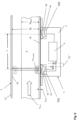
- an apparatus 1 for measuring the flow velocity V med of a fluid 5 in a pipe 2 which is herein after also called flow meter 1, comprises a housing 3 in which a first ultrasonic transducer TD1 and a second ultrasonic transducer TD2 are arranged at a predefined distance L to each other.
- the first ultrasonic transducer TD1 includes a first sound transmitting element 4a and a transmitter/receiver unit 6a which are adapted to emit first ultrasonic pulses P1 at different angles ⁇ 1 .
- the second ultrasonic transducer TD2 is adapted to receive said first ultrasonic pulses P1 and generate a first electronic output signal.
- the second ultrasonic transducer TD2 includes a second sound transmitting element 4b and a second transmitter/receiver unit 6b mounted thereto which are adapted to emit second ultrasonic pulses P2 at different angles ⁇ 2 .
- the first ultrasonic transducer TD1 is adapted to receive said second ultrasonic pulses P2 and generate a second electronic output signal.
- the first and second transducer TD1 and TD2 are connected to a control and evaluation unit 8 which drives both transducers TD1 and TD2 when operated in a transmitting mode and also evaluates the signals received by the transducers, when operated in a receiving mode.
- control and evaluation unit 8 is adapted to vary the angle ⁇ 1 of the ultrasonic pulses P1 which are emitted by the first transducer TD1 when operated in the transmitting mode to an angel which generates a first electronic output signal in the second transducer TD2 that has a maximum amplitude.
- control and evaluation unit 8 is adapted to vary the angle ⁇ 2 of the second ultrasonic pulses which are emitted by the second transducer TD2 when operated in a transmitting mode to an angle which generates an electronic output signal in the first transducer TD1 that has a maximum amplitude.
- the first transducer TD1 of the preferred embodiment of the invention comprises a first transmitter/receiver unit 6a, which is preferably a known piezo actuator and a first wedge shaped element 4a on which the transmitter/receiver unit 6a is mounted at an angle to the outer surface of the pipe.
- the second transducer TD2 includes a second transmitter/receiver unit 6b which is preferably a known piezo actuator and a second wedge shaped element 4b, on which the second transmitter/receiver unit 6a is mounted at an angle inverse to the one of the first wedge shaped element 4a to the outer surface of the pipe wall 12.
- the first and second transducers (TD1, TD2) are identical.
- the first sound transmitting element and/or the second sound transmitting element are wedge shaped elements 4a, 4b as described herein before.
- the wedge shaped elements are preferably plastic wedges or prisms made of e.g. polyurethane, polyamid, polyetherimid or another known plastic material which is able to conduct ultrasonic waves from the transmitter/receiver units 6a, 6b to a contacting area in which the wedge shaped elements 4a, 4b are in contact with the wall 12 of the pipe 2 as shown in Figs 1 and 2 .
- a known ultrasonic gel or a layer of soft plastics, preferably silicone rubber, may be arranged between the wedge shaped elements 4a, 4b and the outer wall surface.
- the ultrasonic waves generated by the transmitter/receiver units 6a, 6b of the first and second transducer TD1, TD2, when operated as an emitter, are diffracted in the sound transmitting elements 4a, 4b and generate vibrations in the wall 12 of the pipe 2 which in turn generate an ultrasonic wave front which is emitted at an angle ⁇ 1 , ⁇ 2 to the inner surface 2a of the pipe 2.
- the angle ⁇ 1 , ⁇ 2 strongly depends on the frequency f1, f2 of the ultrasonic waves which are emitted by the transmitter/receiver units 6a, 6b, so that by tuning the frequency f1, f2 of the transducers (TD1, TD2) over a certain range, e.g. from 100 kHz to 1 MHz, the angel ⁇ 1 , ⁇ 2 of the ultrasonic waves/pulses P1, P2 emitted from the transducers TD1, TD2 into the fluid 5 can be changed.
- the vibrations generated in the wall are typically Lamb waves which can exist in different wave modes having different properties in the interaction with the liquid.
- a preferable mode to be used for the generation of the emitted beam into the fluid is the fundamental asymmetric Lamb wave mode in the wall which is also called A0-mode.
- This asymmetric A0 Lamb wave mode provides for the advantage that it shows a strong interaction with the surrounding liquid and thus emits most of its acoustical energy already along a short travel path into the liquid.
- other known Lamb wave modes with a strong interaction with the liquid may be used.
- the transmitter/receiver units 6a, 6b of the first and second transducer TD1, TD2 can comprise a simple piezoelectric element which is mounted to the wall 12 by means of a sound transmitting element which is configured as a mechanical grating 4' that is located in between the piezoelectric element 6a, 6b and the wall 12, as it is shown in Fig. 8 .
- This grating preferably consists of two different materials, e.g. a first sound-transmitting material like metal and a second non-sound transmitting material like air or plastic, which are arranged in a 1-dimensional or 2-dimensional periodic order.
- the waves/ultrasonic pulses P1, P2 which are generated by the transmitter/receiver units (piezoelectric elements) 6a, 6b can only propagate in one of the materials, e.g. the metal, and are blocked in the other, e.g. the air or plastic, or they propagate with different propagation velocities so that a phase shift of the ultrasonic waves which form the pulses P1, P2 occurs at the wall 12. As applicant has found, this results in a periodical excitation of the acoustic waves in the wall 12, so that only one specific wave front or pulse is emitted at a specific angle ⁇ 1 , ⁇ 2 .
- the angle ⁇ 1 , ⁇ 2 under which the first and second ultrasonic pulses P1, P2 are emitted from the grating 4' into the liquid can be varied, and the angle can be tuned to an angle at which the amplitude of the signal received by the receiving transducer TD2, TD1 has a maximum, as it was set forth herein before with reference to the embodiment in which the sound transmitting elements are configured as wedges 4a, 4b.
- the periodicity is preferably selected in such a way that it fits to the wavelength of the required ultrasonic mode in the wall 12, so that as a result preferably only this mode is excited.
- an electronic grating 104 on the piezoelectric element of the transmitter/receiver units 6a, 6b can be used, in which a periodic electrode structure which comprises two or more nested sets of comb shaped electrodes 105, 106 extending into each other is printed on the outer surface of the piezoelectric element of the transmitter/receiver units 6a, 6b as it is shown in Fig. 9a and 9b .
- the two different sets of electrodes 105, 106 are connected to a frequency tunable signal generator 108, e.g. an AC-power supply which is part of the control and evaluation unit and which can be tuned to a frequency that generates lamb waves in the material of the wall 12.
- the comb shaped arrangement of electrodes 105, 106 also leads to a periodic excitation of acoustic waves in the wall 12 which finally results in ultrasonic pulses P1, P2 that are emitted into the liquid under an angle ⁇ 1 , ⁇ 2 which strongly depends on the frequency of the signals fed to the first and second transmitter/receiver units 6a, 6b.
- a transducer TD1, TD2 which can generate first and second ultrasonic pulses P1, P2 at different emitting angles ⁇ 1 , ⁇ 2
- a plurality of pairs of opposing electrodes 204a, 206b; 204b, 206b; 204c, 206c may be provided on the surface of the piezo electric elements of the transmitter/receiver units 6a, 6b, as it is shown in the exemplary embodiment of Fig. 9 in which 3 pairs of electrodes 204, 206 are shown for demonstrative purposes only.
- Each pair of electrodes 204, 206 is fed by a separate signal generator 208a to 208c with an individual periodic signal having the same frequency but comprising a phase shift.
- the emitting angle ⁇ 1 , ⁇ 2 of the superposed wave front which forms the ultrasonic pulses P1, P2 can be varied at a fixed frequency, as it is e.g. known from ultrasound scanning devices for scanning the human body.
- This embodiment provides for the advantage that the frequency which is fed to the electrodes of the ultrasonic emitter/receiver units 6a, 6b can be set to a desired lamb frequency which fits best for a specific material, and the angle ⁇ 1 , ⁇ 2 can afterwards be varied until the received pulses P1, P2 have a maximum amplitude by altering the phase shift between the pairs of electrodes 204, 206.
- the sound transmitting element may be a known ultrasonic gel or a flat layer of soft plastics 109, preferably silicone rubber as mentioned herein before.
- a further possible variant of a transmitter which is not shown in the drawings may comprise an electromagnetic acoustical transducer (EMAT) in which a more static magnetic field in combination with eddy currents is applied and generated inside the wall material.
- EMAT electromagnetic acoustical transducer
- the interaction between the eddy currents and the magnetic field results in mechanical movements inside the wall which in turn generate ultrasonic waves/pulses propagating in the wall.
- the angle ⁇ 1 of the emitted first pulses P1 is altered until a maximum amplitude signal in transducer TD2 is obtained and the flight time of the pulses P altered is measured by the control and evaluation unit 8.
- the angel ⁇ 1 at which the amplitude of the received signal in the receiving transducer TD2 becomes a maximum is determined by tuning the frequency of the first emitter/receiver unit 6a to a frequency f1 max which generates a maximum signal in the second transducer TD2.
- the angle ⁇ 1 at which the amplitude of the received signal in the receiving transducer TD2 becomes a maximum is determined by tuning the phase between the signals fed to the pairs of electrodes 204a, 206a; 204b, 206b and 204c, 206c by the separate signal generators 208a, 208b and 208c until the signal received by the second Transducer TD2 becomes a maximum.
- the apparatus is operated the other way round as shown in Fig. 2 , in order to measure the flight time T2 of ultrasonic pulses P2 which are emitted by the second transducer TD2 and received by the first transducer TD1.
- the fixed distance L may be obtained by an initial calibration of the apparatus 1 mounted to a known pipe 2 in which a known fluid is streaming with a known speed V med . After calculating and storing the corresponding value L for the (effective distance) from the afore-mentioned mathematical relation in a memory of the micro controller of the control and evaluation unit 8, this effective distance value L may be used for all further applications of the apparatus 1.
- the first transducer TD1 is further driven by the control and evaluation unit 8 to generate lamb waves 10 within the wall material of said pipe 2 having a first frequency f1 lamb .
- the lamb waves which are only schematically indicated in Fig. 3 for illustration purposes propagate inside the wall material and are received by the second transducer TD2.
- the second transducer TD2 which is operated in a receiving mode receives the lamb waves 10 and generates an electronic signal having a frequency f1 lamb which is transmitted to the control and evaluation unit 8.
- the first transducer TD1 is further driven in a transmitting/receiving mode in which the transmitter/receiver unit 6a is first operated as a transmitter and transmits a short pulse P1 of the afore-mentioned lamb waves 10 of a known first frequency f1 lamb .
- the first transducer TD1 is switched to the receiving mode in which the transmitter/receiver unit 6a is operated as a receiver which receives the lamb waves 10 which are travelling around the perimeter U of the pipe 2 in the pipe wall 12 .
- the perimeter U and the diameter D are not the exact perimeter /diameter values of the pipe, but are averaged values of the perimeter/diameter measured at about half way of the wall thickness.
- the apparatus according to the invention has the advantage that all of the afore-mentioned parameters can be measured without knowing any details about the pipe parameters itself which makes the apparatus highly flexible and allows the device to be used as a mobile, preferably also hand held clamp-on device for different kind of measuring applications.
- lamb wave modes with a low interaction with the surrounded liquid are used as e.g. the fundamental symmetric Lamb wave mode (so called SO-mode).
- the housing 3 of the apparatus 1 is adapted to be preferably releasable mounted at the bottom surface of a pipe 2, e.g. by means of holding flanges and straps (not shown) wrapped around the pipe or by magnets or releasable glue or the like.
- the apparatus 1 is operated similar to the embodiment of Fig. 3 for measuring the diameter D of the pipe 2 which is completely filled.
- the first transducer TD1 may be configured and controlled by the control and evaluation unit 8 to generate first ultrasonic pulses P1 parallel which are emitted in a direction parallel to the diameter D of the pipe 2 and receive reflections of the emitted ultrasonic pulses P1 parallel which are reflected at an adjacent inner wall surface 2a (not shown in detail) and/or at an upper surface 5a of the fluid 5 in a partially filled pipe 2 and/or at the inner wall surface 2a of the pipe 2 which is located opposite to said first transducer TD1, as shown in Fig. 6 .
- the second ultrasonic transducer TD2 may be employed instead of using the first transducer TD1 for generating the lamb waves 10 and ultrasonic pulses P1 parallel .
- the ultrasonic pulses P1 parallel are generated and received by the first transducer TD1 and the lamb waves 10 running through the wall 2 for measuring the sonic speed in the wall material are generated in the same configuration by the second transducer TD2 and vice versa.
- This provides for the advantage of an increased measuring speed and a shortened measuring time or even an improved measuring accuracy when repeating the measurements several time and calculating an average value from a series of measured single values.
- a method of measuring the flow velocity V med of a fluid 5 in a pipe 2 comprises the following steps:
- the method comprises the further method steps of
- the above-described method may comprise the further method steps of
- the diameter obtained from a runtime measurement of lamb waves 10 running in the wall 12 of the pipe may be used to calculate whether a pipe 2 is completely or only partially filled with a liquid medium 5.
- the control and evaluation unit 8 calculates if the measured diameter D or Di is equal to H fluid or not. If the measured value of H fluid is smaller than D or D i the pipe 2 is only partially filled.
- the values and parameters which can be measured with the apparatus 1 may be displayed on a display mounted to or included in the housing 3 and/or stored in the memory of the control and evaluation unit 8 and/or may be transmitted to a remote server or central control unit (not shown), e.g. via a known data communication network.
Landscapes
- Physics & Mathematics (AREA)
- General Physics & Mathematics (AREA)
- Electromagnetism (AREA)
- Fluid Mechanics (AREA)
- Life Sciences & Earth Sciences (AREA)
- Health & Medical Sciences (AREA)
- Acoustics & Sound (AREA)
- Chemical & Material Sciences (AREA)
- Analytical Chemistry (AREA)
- Biochemistry (AREA)
- General Health & Medical Sciences (AREA)
- Immunology (AREA)
- Pathology (AREA)
- Measuring Volume Flow (AREA)
Claims (8)
- Gerät (1) zum Messen der Strömungsgeschwindigkeit (Vmed) eines Fluids (5) in einem Rohr (2) mit einem kreisförmigen Querschnitt, umfassend ein Gehäuse (3), in dem ein erster Ultraschallwandler (TD1) und ein zweiter Ultraschallwandler (TD2) in einem vordefinierten Wirkabstand (L) zueinander angeordnet sind, wobei der erste Ultraschallwandler (TD1) ein erstes Schallübertragungselement (4a) und eine daran montierte Sender-/Empfängereinheit (6a) umfasst, die dazu eingerichtet sind, erste Ultraschallimpulse (P1) in unterschiedlichen Winkeln in dem Fluid zu emittieren, und der zweite Ultraschallwandler (TD2) dazu eingerichtet ist, die ersten Ultraschallimpulse (P1) zu empfangen und ein erstes elektronisches Ausgangssignal zu erzeugen, und wobei der zweite Ultraschallwandler (TD2) ein zweites Schallübertragungselement (4b) und eine daran montierte Sender-/Empfängereinheit (6b) umfasst, die dazu eingerichtet sind, zweite Ultraschallimpulse (P2) in unterschiedlichen Winkeln in dem Fluid zu emittieren, und wobei der erste Ultraschallwandler (TD1) dazu eingerichtet ist, die zweiten Ultraschallimpulse (P2) zu empfangen und ein zweites elektronisches Ausgangssignal zu erzeugen, eine Steuer- und Auswerteeinheit (8), die elektrisch mit dem ersten und zweiten Wandler (TD1, TD2) gekoppelt ist, wobei die Steuer- und Auswerteeinheit (8) dazu eingerichtet ist, den ersten Wandler (TD1) abzustimmen, um den Winkel der ersten Ultraschallimpulse (P1) auf einen Winkel zu verändern, der ein erstes elektronisches Ausgangssignal in dem zweiten Wandler (TD2) mit einer maximalen Amplitude erzeugt, und den zweiten Wandler (TD2) abzustimmen, um den Winkel der zweiten Ultraschallimpulse (P2) auf einen Winkel zu verändern, der ein zweites elektronisches Ausgangssignal in dem ersten Wandler (TD1) mit einer maximalen Amplitude erzeugt, und wobei die Steuer- und Auswerteeinheit (8) dazu eingerichtet ist, die Laufzeit (T1) der ersten Ultraschallimpulse (P1) in dem Fluid von dem ersten Ultraschallwandler (TD1) zu dem zweiten Ultraschallwandler (TD2) zu messen und die Laufzeit (T2) der zweiten Ultraschallimpulse (P2) in dem Fluid von dem zweiten Ultraschallwandler (TD2) zu dem ersten Ultraschallwandler (TD1) zu messen; und wobei die Steuer- und Auswerteeinheit dazu ausgelegt ist, eine Strömungsgeschwindigkeit des Fluids in dem Rohr auf Basis des vordefinierten Wirkabstands (L) und der Laufzeit (T1) der ersten Ultraschallimpulse (P1) in dem Fluid von dem ersten Ultraschallwandler (TD1) zu dem zweiten Ultraschallwandler (TD2) und der Laufzeit (T2) der zweiten Ultraschallimpulse (P2) in dem Fluid von dem zweiten Ultraschallwandler (TD2) zu dem ersten Ultraschallwandler (TD1) zu bestimmen;dadurch gekennzeichnet, dass der erste Ultraschallwandler (TD1) ferner dazu ausgelegt ist, Lambwellen in einer Wand (12) des Rohrs zu erzeugen, wobei die Lambwellen mindestens in einer Längenrichtung des Rohrs und in einer Umfangsrichtung des Rohrs emittiert werden, und wobei der zweite Ultraschallwandler (TD2) dazu ausgelegt ist, die in der Längenrichtung des Rohrs emittierten Lambwellen zu empfangen, und wobei die Steuer- und Auswerteeinheit (8) dazu ausgelegt ist, eine Laufzeit (T flight TD1-TD2) der Lambwellen in der Wand (12) zwischen dem ersten Ultraschallwandler (TD1) und dem zweiten Ultraschallwandler (TD2) zu messen, und wobei die Steuer- und Auswerteeinheit (8) dazu ausgelegt ist, eine Schallgeschwindigkeit (Cf1lamb) der Lambwellen auf Basis der Laufzeit (T flight TD1-TD2) der Lambwellen in der Wand (12) zwischen dem ersten Ultraschallwandler (TD1) und dem zweiten Ultraschallwandler (TD2) zu bestimmen;und dadurch, dass der erste Ultraschallwandler (TD1) ferner dazu ausgelegt ist, die in der Umfangsrichtung des Rohrs emittierten Lambwellen zu empfangen, und wobei die Steuer- und Auswerteeinheit (8) dazu ausgelegt ist, eine Laufzeit (T flight TD1-TD1) der Lambwellen zu messen, die um einen Umfang des Rohrs (2) in der Rohrwand (12) von dem ersten Ultraschallwandler (TD1) und zurück zu dem ersten Ultraschallwandler (TD1) wandern; undwobei die Steuer- und Auswerteeinheit (8) dazu ausgelegt ist, eine Länge (U) des Umfangs des Rohrs auf Basis der Schallgeschwindigkeit der Lambwellen (Cf1lamb) und der Laufzeit (T flight TD1-TD1) der Lambwellen zu bestimmen, die um den Umfang des Rohrs (2) in der Rohrwand (12) von dem ersten Ultraschallwandler (TD1) und zurück zu dem ersten Ultraschallwandler (TD1) wandern; unddadurch, dass die Steuer- und Auswerteeinheit dazu ausgelegt ist, einen Volumenstrom des Fluids in dem Rohr auf Basis einer Strömungsgeschwindigkeit des Fluids in dem Rohr und der Länge des Umfangs des Rohrs zu bestimmen.
- Gerät gemäß Anspruch 1,
wobei
das Gehäuse (3) dazu eingerichtet ist, an der Unterseite des Rohrs (2) montiert zu sein, und dass der erste Wandler (TD1) ferner dazu eingerichtet ist, erste Ultraschallimpulse (P1 parallel) zu erzeugen, die in einer Richtung parallel zu dem Durchmesser (D) des Rohrs (2) emittiert werden, und der erste Wandler (TD1) ferner dazu eingerichtet ist, Reflexionen der emittierten Ultraschallimpulse (P1 parallel) zu empfangen, die an einer angrenzenden Wandinnenfläche (2a) des Rohrs und/oder an einer Oberfläche (5a) des Fluids (5) in einem teilweise gefüllten Rohr (2) und/oder an der Wandinnenfläche (2a) des Rohrs (2), die gegenüber dem ersten Wandler (TD1) angeordnet ist, reflektiert werden, und wobei die Steuer- und Auswerteeinheit (8) ferner dazu eingerichtet ist, aus der durch den ersten Wandler (TD1) empfangenen Laufzeit (T1'), (T1") und (T1‴) der reflektierten Ultraschallimpulse (P1 parallel) die Wanddicke (dwall) des Rohrs (2) und/oder die Füllhöhe (Hfluid) eines Fluids (5) in einem teilweise gefüllten Rohr (2) und/oder den Innendurchmesser (Di) des Rohrs (2) gemäß den folgenden Beziehungen zu bestimmen:

 T1' die Laufzeit der durch den ersten Wandler (TD1) emittierten und empfangenen ersten Ultraschallimpulse (P1 parallel) ist, die an der Innenfläche (2a) der Rohrwand auf der Seite des Rohrs (2) reflektiert werden, die dem ersten Wandler (TD1) gegenüberliegt,T1" die Laufzeit der durch den ersten Wandler (TD1) emittierten und empfangenen ersten Ultraschallimpulse (P1 parallel) ist, die an einer Fläche (5a) des Fluids (5) in einem teilweise gefüllten Rohr (2) reflektiert werden,T1‴ die Laufzeit der durch den ersten Wandler (TD1) emittierten und empfangenen ersten Ultraschallimpulse (P1 parallel) ist, die an der angrenzenden Innenfläche (2a) der Rohrwand reflektiert werden,Di der Innendurchmesser des Rohrs (2) ist,Cmed die Schallgeschwindigkeit der ersten Ultraschallimpulse (P1 parallel) in dem Fluid (5) ist, undCwall die Schallgeschwindigkeit der ersten Ultraschallimpulse (P1 parallel) in dem Wandmaterial ist, die durch den ersten Wandler (TD1) in einer Richtung parallel zu dem Durchmesser (D) des Rohrs (2) emittiert werden; unddie Steuer- und Auswerteeinheit (8) ferner dazu eingerichtet ist, die Schallgeschwindigkeit (Cmed) in dem durch das Rohr (2) fließenden Fluid (5) gemäß der folgenden Beziehung zu bestimmen:
 T1 die Laufzeit der ersten Ultraschallimpulse (P1) ist, die durch den ersten Wandler (TD1) in einer Richtung parallel zu dem Durchmesser D des Rohrs (2) emittiert und durch den zweiten Wandler (TD2) in einem vollständig gefüllten Rohr (2) empfangen werden,T2 die Laufzeit der zweiten Ultraschallimpulse (P2) ist, die durch den zweiten Wandler (TD2) in einer Richtung parallel zu dem Durchmesser (D) des Rohrs (2) emittiert und durch den ersten Wandler (TD1) in einem vollständig gefüllten Rohr (2) empfangen werden,L der vorbestimmte Abstand zwischen dem ersten Wandler (TD1) und dem zweiten Wandler (TD2) in dem Gehäuse (3) ist,D der Durchmesser des Rohrs (2) ist,U der Umfang des Rohrs (2) ist, undπ 3,1415 ist.
 - Gerät gemäß einem der vorhergehenden Ansprüche, wobei das Gehäuse (3) lösbar an dem Rohr montierbar ist.
- Gerät gemäß einem der vorhergehenden Ansprüche, wobei das erste Schallübertragungselement ein keilförmiges Element (4a) oder ein mechanisches Gitter (4') ist, das zwischen der ersten Sender-/Empfängereinheit (6a) und einer Wand (12) des Rohrs angeordnet ist, und/oder die erste Sender-/Empfängereinheit (6a) und das erste Schallübertragungselement ein piezoelektrisches Element umfassen, das ein elektronisches Gitter (104) mit daran angeordneten Elektroden (105, 106) umfasst, das dazu eingerichtet ist, mit einer Wand (12) des Rohrs mittels des Schallübertragungselements (109) in Kontakt zu kommen.
- Verfahren zum Messen der Strömungsgeschwindigkeit (Vmed) eines Fluids (5) in einem Rohr (2) mit einem kreisförmigen Querschnitt mit einem Gerät gemäß einem der Ansprüche 1-4, wobei das Verfahren Folgendes umfasst:Abstimmen, mit der Steuer- und Auswerteeinheit, des ersten Wandlers (TD1), um den Winkel der ersten Ultraschallimpulse (P1) auf einen Winkel zu verändern, der ein erstes elektronisches Ausgangssignal in dem zweiten Wandler (TD2) mit einer maximalen Amplitude erzeugt;Abstimmen, mit der Steuer- und Auswerteeinheit, des zweiten Wandlers (TD2), um den Winkel der zweiten Ultraschallimpulse (P2) auf einen Winkel zu verändern, der ein zweites elektronisches Ausgangssignal in dem ersten Wandler (TD1) mit einer maximalen Amplitude erzeugt;Messen, mit der Steuer- und Auswerteeinheit (8), der Laufzeit (T1) der ersten Ultraschallimpulse (P1) in dem Fluid von dem ersten Ultraschallwandler (TD1) zu dem zweiten Ultraschallwandler (TD2);Messen, mit der Steuer- und Auswerteeinheit (89, der Laufzeit (T2) der zweiten Ultraschallimpulse (P2) in dem Fluid von dem zweiten Ultraschallwandler (TD2) zu dem ersten Ultraschallwandler (TD1);Bestimmen, mit der Steuer- und Auswerteeinheit, einer Strömungsgeschwindigkeit des Fluids in dem Rohr auf Basis des vordefinierten Wirkabstands (L) und der Laufzeit (T1) der ersten Ultraschallimpulse (P1) in dem Fluid von dem ersten Ultraschallwandler (TD1) zu dem zweiten Ultraschallwandler (TD2) und der Laufzeit (T2) der zweiten Ultraschallimpulse (P2) in dem Fluid von dem zweiten Ultraschallwandler (TD2) zu dem ersten Ultraschallwandler (TD1);dadurch gekennzeichnet, dass das Verfahren ferner Folgendes umfasst:Erzeugen, durch den ersten Ultraschallwandler (TD1), von Lambwellen in einer Wand (12) des Rohrs, wobei die Lambwellen mindestens in einer Längenrichtung des Rohrs und in einer Umfangsrichtung des Rohrs emittiert werden, und das Empfangen, durch den zweiten Ultraschallwandler (TD2), der in der Längenrichtung des Rohrs emittierten Lambwellen, und Messen, mit der Steuer- und Auswerteeinheit (8), einer Laufzeit (T flight TD1-TD2) der Lambwellen in der Wand (12) zwischen dem ersten Ultraschallwandler (TD1) und dem zweiten Ultraschallwandler (TD2);Bestimmen, durch die Steuer- und Auswerteeinheit, einer Schallgeschwindigkeit (Cf1lamb) der Lambwellen auf Basis der Laufzeit (T flight TD1-TD2) der Lambwellen in der Wand (12) zwischen dem ersten Ultraschallwandler (TD1) und dem zweiten Ultraschallwandler (TD2);Empfangen, durch den ersten Ultraschallwandler (TD1), der in der Umfangsrichtung des Rohrs emittierten Lambwellen, und Messen, durch die Steuer- und Auswerteeinheit (8), einer Laufzeit (T flight TD1-TD1) der Lambwellen, die um einen Umfang des Rohrs (2) in der Rohrwand (12) von dem ersten Ultraschallwandler (TD1) und zurück zu dem ersten Ultraschallwandler (TD1) wandern;Bestimmen, durch die Steuer- und Auswerteeinheit, einer Länge (U) des Umfangs des Rohrs auf Basis der Schallgeschwindigkeit der Lambwellen (Cf1lamb) und der Laufzeit (T flight TD1-TD1) der Lambwellen, die um den Umfang des Rohrs (2) in der Rohrwand (12) von dem ersten Ultraschallwandler (TD1) und zurück zu dem ersten Ultraschallwandler (TD1) wandern; undBestimmen, durch die Steuer- und Auswerteeinheit, eines Volumenstroms des Fluids in dem Rohr auf Basis der Strömungsgeschwindigkeit des Fluids in dem Rohr und der Länge des Umfangs des Rohrs.
- Verfahren gemäß Anspruch 5,
wobeidas Gehäuse (3) dazu eingerichtet ist, auf der Unterseite des Rohrs (2) montiert zu sein, und wobei das Verfahren Folgendes umfasstErzeugen, durch den ersten Wandler (TD1), von ersten Ultraschallimpulsen (P1 parallel), die in einer Richtung parallel zu dem Durchmesser (D) des Rohrs (2) emittiert werden, und Empfangen, durch den ersten Wandler (TD1), von Reflexionen der emittierten Ultraschallimpulse (P1 parallel), die an einer angrenzenden Wandinnenfläche (2a) des Rohrs und/oder an einer Oberfläche (5a) des Fluids (5) in einem teilweise gefüllten Rohr (2) und/oder an der Wandinnenfläche (2a) des Rohrs (2), die sich gegenüber dem ersten Wandler (TD1) befindet, reflektiert werden, und Bestimmen, durch die Steuer- und Auswerteeinheit (8) aus der durch den ersten Wandler (TD1) empfangenen Laufzeit (T1'), (T1") und (T1‴) der reflektierten Ultraschallimpulse (P1 parallel), der Wanddicke (dwall) des Rohrs (2) und/oder der Füllhöhe (Hfluid) eines Fluids (5) in einem teilweise gefüllten Rohr (2) und/oder des Innendurchmessers (Di) des Rohrs (2) gemäß den folgenden Beziehungen:

 T1' die Laufzeit der durch den ersten Wandler (TD1) emittierten und empfangenen ersten Ultraschallimpulse (P1 parallel) ist, die an der Innenfläche (2a) der Rohrwand auf der Seite des Rohrs (2) reflektiert werden, die dem ersten Wandler (TD1) gegenüberliegt,T1" die Laufzeit der durch den ersten Wandler (TD1) emittierten und empfangenen ersten Ultraschallimpulse (P1 parallel) ist, die an einer Fläche (5a) des Fluids (5) in einem teilweise gefüllten Rohr (2) reflektiert werden,T1‴ die Laufzeit der durch den ersten Wandler (TD1) emittierten und empfangenen ersten Ultraschallimpulse (P1 parallel) ist, die an der angrenzenden Innenfläche (2a) der Rohrwand reflektiert werden,Di der Innendurchmesser des Rohrs (2) ist,Cmed die Schallgeschwindigkeit der ersten Ultraschallimpulse (P1 parallel) in dem Fluid (5) ist, undCwall die Schallgeschwindigkeit der ersten Ultraschallimpulse (P1 parallel) in dem Wandmaterial ist, die durch den ersten Wandler (TD1) in einer Richtung parallel zu dem Durchmesser (D) des Rohrs (2) emittiert werden; undBestimmen, durch die Steuer- und Auswerteeinheit (8), der Schallgeschwindigkeit (Cmed) in dem durch das Rohr (2) fließenden Fluid (5) gemäß der folgenden Beziehung:
 T1 die Laufzeit der ersten Ultraschallimpulse (P1) ist, die durch den ersten Wandler (TD1) in einer Richtung parallel zu dem Durchmesser D des Rohrs (2) emittiert und durch den zweiten Wandler (TD2) in einem vollständig gefüllten Rohr (2) empfangen werden,T2 die Laufzeit der zweiten Ultraschallimpulse (P2) ist, die durch den zweiten Wandler (TD2) in einer Richtung parallel zu dem Durchmesser (D) des Rohrs (2) emittiert und durch den ersten Wandler (TD1) in einem vollständig gefüllten Rohr (2) empfangen werden,L der vorbestimmte Abstand zwischen dem ersten Wandler (TD1) und dem zweiten Wandler (TD2) in dem Gehäuse (3) ist,D der Durchmesser des Rohrs (2) ist,U der Umfang des Rohrs (2) ist, undπ 3,1415 ist.
 - Verfahren gemäß einem der Ansprüche 5-6,
wobei das Gehäuse (3) lösbar an dem Rohr montierbar ist. - Verfahren gemäß einem der Ansprüche 5-7,
wobei das erste Schallübertragungselement ein keilförmiges Element (4a) oder ein mechanisches Gitter (4') ist, das zwischen der ersten Sender-/Empfängereinheit (6a) und einer Wand (12) des Rohrs angeordnet ist, und/oder die erste Sender-/Empfängereinheit (6a) und das erste Schallübertragungselement ein piezoelektrisches Element umfassen, das ein elektronisches Gitter (104) mit daran angeordneten Elektroden (105, 106) umfasst, das dazu eingerichtet ist, mit einer Wand (12) des Rohrs mittels des Schallübertragungselements (109) in Kontakt zu kommen.
Applications Claiming Priority (2)
| Application Number | Priority Date | Filing Date | Title |
|---|---|---|---|
| EP17159550 | 2017-03-07 | ||
| PCT/EP2018/055148 WO2018162340A1 (en) | 2017-03-07 | 2018-03-02 | Apparatus and method for measuring the flow velocity of a fluid in a pipe |
Publications (2)
| Publication Number | Publication Date |
|---|---|
| EP3593093A1 EP3593093A1 (de) | 2020-01-15 |
| EP3593093B1 true EP3593093B1 (de) | 2024-02-21 |
Family
ID=58261576
Family Applications (1)
| Application Number | Title | Priority Date | Filing Date |
|---|---|---|---|
| EP18707919.9A Active EP3593093B1 (de) | 2017-03-07 | 2018-03-02 | Vorrichtung und verfahren zur messung der strömungsgeschwindigkeit eines fluids in einem rohr |
Country Status (4)
| Country | Link |
|---|---|
| US (1) | US11215489B2 (de) |
| EP (1) | EP3593093B1 (de) |
| CN (1) | CN110383014B (de) |
| WO (1) | WO2018162340A1 (de) |
Families Citing this family (15)
| Publication number | Priority date | Publication date | Assignee | Title |
|---|---|---|---|---|
| JP6894863B2 (ja) * | 2018-03-14 | 2021-06-30 | 株式会社キーエンス | クランプオン式超音波流量センサ |
| DE102018132055B4 (de) * | 2018-12-13 | 2022-08-25 | Endress + Hauser Flowtec Ag | Ultraschallwandleranordnung einer Clamp-On-Ultraschall-Durchflussmessstelle, und eine Clamp-On-Ultraschall-Durchflussmessstelle sowie Verfahren zur Inbetriebnahme der Clamp-On-Ultraschall-Durchflussmessstelle |
| CN110455230A (zh) * | 2019-09-26 | 2019-11-15 | 西安热工研究院有限公司 | 一种高温管道周长在线监测系统及方法 |
| CN110470254B (zh) * | 2019-09-26 | 2024-08-06 | 西安热工研究院有限公司 | 一种管道蠕变测量系统及方法 |
| US11359950B2 (en) | 2019-12-10 | 2022-06-14 | Johnson Controls Tyco IP Holdings LLP | Reduced length valve assembly with ultrasonic flow sensor |
| EP4081763A1 (de) * | 2019-12-23 | 2022-11-02 | Belimo Holding AG | System und verfahren zur messung eines gasflusses durch einen kanal |
| DE102020127360A1 (de) | 2020-10-16 | 2022-04-21 | Endress + Hauser Flowtec Ag | Verfahren zur Verifikation eines Clamp-On-Ultraschall-Messgeräts |
| CN119301425A (zh) * | 2022-04-29 | 2025-01-10 | 森西亚荷兰有限公司 | 具有不对称换能器窗口的超声波流量计 |
| WO2023227652A1 (de) * | 2022-05-24 | 2023-11-30 | Ifm Electronic Gmbh | Ultraschall-durchflussmessvorrichtung zum bestimmen eines durchflusses eines fluiden mediums durch eine rohrleitung |
| CN115163038B (zh) * | 2022-08-18 | 2026-04-28 | 西安思坦仪器股份有限公司 | 一种油田分注井的外置式流量测量装置、配水器及流量测量方法 |
| WO2024137605A1 (en) * | 2022-12-22 | 2024-06-27 | Lixil Corporation | Ultrasonic monitoring device and system |
| CN116164801A (zh) * | 2023-01-16 | 2023-05-26 | 华能南京金陵发电有限公司 | 一种火电机组烟气流量测量系统及方法 |
| DE102023130466B3 (de) | 2023-11-03 | 2025-01-23 | Ifm Electronic Gmbh | Verfahren zum Bestimmen eines Durchflusses eines fluiden Mediums durch eine Rohrleitung sowie eine Messvorrichtung |
| TW202526362A (zh) * | 2023-12-26 | 2025-07-01 | 大陸商茂丞(鄭州)超聲科技有限公司 | 超聲波模組及應用其之超聲波滑鼠 |
| DE102024121074A1 (de) | 2024-07-24 | 2026-01-29 | Sensaru GmbH | Ultraschall-Durchflussmessvorrichtung |
Citations (1)
| Publication number | Priority date | Publication date | Assignee | Title |
|---|---|---|---|---|
| EP3115753B1 (de) * | 2015-07-06 | 2022-01-05 | ABB Schweiz AG | System und verfahren zur nicht-invasiven und kontinuierlichen füllstandsmessung einer flüssigkeit |
Family Cites Families (35)
| Publication number | Priority date | Publication date | Assignee | Title |
|---|---|---|---|---|
| US4024760A (en) * | 1975-07-25 | 1977-05-24 | Westinghouse Electric Corporation | Fluid flow measurement apparatus |
| US4109523A (en) * | 1977-10-21 | 1978-08-29 | Westinghouse Electric Corp. | Method of determining acoustic flow meter correction factor |
| US4432243A (en) * | 1979-02-28 | 1984-02-21 | Ocean Research Equipment, Inc. | Flow calculator with velocity curve fitting circuit means |
| US4317178A (en) * | 1979-03-01 | 1982-02-23 | Fischer & Porter Company | Multiple velocity traverse flow rate measuring technique |
| JPS6098313A (ja) * | 1983-11-02 | 1985-06-01 | Fuji Electric Co Ltd | 超音波流量計 |
| JP2543505B2 (ja) * | 1986-07-22 | 1996-10-16 | 安川商事 株式会社 | 時空間微分法を用いた信号処理装置および計測装置 |
| US5251487A (en) * | 1989-03-29 | 1993-10-12 | Martin Marietta Corporation | Apparatus for acoustically coupling an ultrasonic transducer with a body |
| DE4241226A1 (de) * | 1992-12-08 | 1994-06-09 | Abb Patent Gmbh | Durchflußmeßvorrichtung |
| WO1995017650A1 (de) | 1993-12-23 | 1995-06-29 | Endress + Hauser Flowtec Ag | Clamp-on-ultraschall-volumendurchfluss-messgerät |
| SE9800074D0 (sv) * | 1998-01-15 | 1998-01-15 | Siemens Elema Ab | Acoustic flow meter |
| US6067861A (en) * | 1998-06-18 | 2000-05-30 | Battelle Memorial Institute | Method and apparatus for ultrasonic doppler velocimetry using speed of sound and reflection mode pulsed wideband doppler |
| US6158288A (en) * | 1999-01-28 | 2000-12-12 | Dolphin Technology, Inc. | Ultrasonic system for measuring flow rate, fluid velocity, and pipe diameter based upon time periods |
| JP2001133306A (ja) * | 1999-11-04 | 2001-05-18 | Nippon Soken Inc | 音波による伝搬時間の測定方法、測定装置及び流量測定装置 |
| US6595071B1 (en) * | 2000-01-06 | 2003-07-22 | Transoma Medical, Inc. | Estimation of error angle in ultrasound flow measurement |
| DE10012395B4 (de) * | 2000-03-15 | 2010-04-29 | Abb Research Ltd. | Durchflussmesser |
| DE102005018396A1 (de) * | 2005-04-20 | 2006-10-26 | Endress + Hauser Flowtec Ag | Verfahren zur Bestimmung des Volumen- oder Massedurchflusses eines Mediums |
| DE102006000693A1 (de) * | 2006-01-02 | 2007-07-05 | Endress + Hauser Flowtec Ag | Vorrichtung zur Bestimmung und/oder Überwachung des Volumen- oder des Massedurchflusses eines Mediums |
| WO2009071870A1 (en) * | 2007-12-05 | 2009-06-11 | Schlumberger Technology B.V. | Ultrasonic clamp-on multiphase flowmeter |
| MX341582B (es) * | 2009-08-18 | 2016-08-25 | Rubicon Res Pty Ltd | Ensamble de medidor de flujo, ensambles de compuerta y metodos para medicion de flujo. |
| DE102010056279B4 (de) * | 2010-12-24 | 2013-07-04 | Abb Technology Ag | Vortex-Durchflussmessgerät mit optimierter Temperaturerfassung |
| JP6124410B2 (ja) * | 2011-03-18 | 2017-05-10 | ソネター, インク.Soneter, Inc. | 流体流測定方法および装置 |
| US8700344B2 (en) * | 2011-04-20 | 2014-04-15 | Neptune Technology Group Inc. | Ultrasonic flow meter |
| DE102011075997A1 (de) * | 2011-05-17 | 2012-11-22 | Endress + Hauser Flowtec Ag | Ultraschall-Durchflussmessgerät |
| GB2504297A (en) * | 2012-07-24 | 2014-01-29 | Titan Entpr Ltd | Acoustic flow meter |
| US20140107950A1 (en) * | 2012-10-12 | 2014-04-17 | Texas Instruments Incorporated | Bandpass adc sampling for fluid velocity determination |
| JP5971428B2 (ja) * | 2013-10-23 | 2016-08-17 | 富士電機株式会社 | 流体計測装置 |
| US9494454B2 (en) * | 2013-12-06 | 2016-11-15 | Joseph Baumoel | Phase controlled variable angle ultrasonic flow meter |
| US10801868B2 (en) * | 2014-06-10 | 2020-10-13 | Texas Instruments Incorporated | Extended range ADC flow meter |
| CN106716172B (zh) * | 2014-08-14 | 2020-06-05 | 皇家飞利浦有限公司 | 用于流体池检测和识别的声流 |
| CN105738649B (zh) * | 2014-12-10 | 2020-02-07 | 通用电气公司 | 用于计算流速的系统和方法 |
| US9752907B2 (en) * | 2015-04-14 | 2017-09-05 | Joseph Baumoel | Phase controlled variable angle ultrasonic flow meter |
| EP3115755B1 (de) * | 2015-07-06 | 2022-02-16 | ABB Schweiz AG | System und verfahren zur messung einer schallgeschwindigkeit in einer flüssigen oder gasförmigen medium |
| CN105181997A (zh) * | 2015-08-20 | 2015-12-23 | 天津市众中科技发展有限公司 | 非接触式超声波水流流速计及非接触式流速检测方法 |
| CN106153132B (zh) * | 2016-06-23 | 2020-03-27 | 西南大学 | 基于Lamb波的非接触式流体流量测量系统及方法 |
| FR3099586B1 (fr) * | 2019-07-29 | 2021-08-06 | Supersonic Imagine | Système ultrasonore pour détecter un flux d’un fluide dans un milieu |
-
2018
- 2018-03-02 CN CN201880016617.9A patent/CN110383014B/zh active Active
- 2018-03-02 EP EP18707919.9A patent/EP3593093B1/de active Active
- 2018-03-02 WO PCT/EP2018/055148 patent/WO2018162340A1/en not_active Ceased
-
2019
- 2019-09-05 US US16/561,139 patent/US11215489B2/en active Active
Patent Citations (1)
| Publication number | Priority date | Publication date | Assignee | Title |
|---|---|---|---|---|
| EP3115753B1 (de) * | 2015-07-06 | 2022-01-05 | ABB Schweiz AG | System und verfahren zur nicht-invasiven und kontinuierlichen füllstandsmessung einer flüssigkeit |
Non-Patent Citations (1)
| Title |
|---|
| CHUL-HO LEE ET AL: "An implementation of ultrasonic water meter using dToF measurement", COGENT ENGINEERING, vol. 4, no. 1, 29 August 2017 (2017-08-29), XP055477650, DOI: 10.1080/23311916.2017.1371577 * |
Also Published As
| Publication number | Publication date |
|---|---|
| CN110383014B (zh) | 2022-01-04 |
| EP3593093A1 (de) | 2020-01-15 |
| US11215489B2 (en) | 2022-01-04 |
| CN110383014A (zh) | 2019-10-25 |
| US20190390991A1 (en) | 2019-12-26 |
| WO2018162340A1 (en) | 2018-09-13 |
Similar Documents
| Publication | Publication Date | Title |
|---|---|---|
| EP3593093B1 (de) | Vorrichtung und verfahren zur messung der strömungsgeschwindigkeit eines fluids in einem rohr | |
| US11035708B2 (en) | Clamp-on ultrasonic sensor having coupling element adapted for respective measuring tube | |
| RU2478190C2 (ru) | Способ и измерительная система для определения и/или контроля расхода измеряемой среды через измерительную трубу | |
| US7069793B2 (en) | Ultrasonic flow meter and ultrasonic sensor | |
| JP4782327B2 (ja) | クランプオン型超音波流量計 | |
| EP3115755A1 (de) | System und verfahren zur messung einer schallgeschwindigkeit in einer flüssigen oder gasförmigen mediumsspezifikation | |
| US9752907B2 (en) | Phase controlled variable angle ultrasonic flow meter | |
| JP2003075219A (ja) | クランプオン型超音波流量計 | |
| KR20040065555A (ko) | 관 또는 홈형상의 유로를 이동하는 유체유량의 측정방법 | |
| KR101951533B1 (ko) | 초음파 유량계 | |
| KR20150141876A (ko) | 클램프온식 초음파 유량계 및 유량 계측 방법 | |
| CN100383495C (zh) | 用于在容器上定位夹合式流量计的设备 | |
| US20200209028A1 (en) | Ultrasonic Gas Flowmeter | |
| EP3710795B1 (de) | Vorrichtung und verfahren zur detektion von abscheidungsschichten in einer leitung zum transport einer flüssigkeit oder eines weichen mediums und/oder zur pegeldetektion | |
| KR101195438B1 (ko) | 초음파 유량계 및 초음파 유량측정방법 | |
| JPWO2006040996A1 (ja) | 超音波流量計 | |
| JP2009109299A (ja) | 流量測定装置 | |
| JP6149250B2 (ja) | 超音波流量計 | |
| EP2074388B1 (de) | Durchflussmesser basierend auf einem piezoelektrischen polymer | |
| JP2017187310A (ja) | 超音波流量計 | |
| JP2004524515A (ja) | 超音波変換器および超音波流量計 | |
| JP2000298045A5 (de) | ||
| JP2005077146A (ja) | 超音波流量計 | |
| JP2008151812A (ja) | 超音波流量計 | |
| JP4179896B2 (ja) | 超音波流量計 |
Legal Events
| Date | Code | Title | Description |
|---|---|---|---|
| STAA | Information on the status of an ep patent application or granted ep patent |
Free format text: STATUS: UNKNOWN |
|
| STAA | Information on the status of an ep patent application or granted ep patent |
Free format text: STATUS: THE INTERNATIONAL PUBLICATION HAS BEEN MADE |
|
| TPAC | Observations filed by third parties |
Free format text: ORIGINAL CODE: EPIDOSNTIPA |
|
| PUAI | Public reference made under article 153(3) epc to a published international application that has entered the european phase |
Free format text: ORIGINAL CODE: 0009012 |
|
| STAA | Information on the status of an ep patent application or granted ep patent |
Free format text: STATUS: REQUEST FOR EXAMINATION WAS MADE |
|
| 17P | Request for examination filed |
Effective date: 20190726 |
|
| AK | Designated contracting states |
Kind code of ref document: A1 Designated state(s): AL AT BE BG CH CY CZ DE DK EE ES FI FR GB GR HR HU IE IS IT LI LT LU LV MC MK MT NL NO PL PT RO RS SE SI SK SM TR |
|
| AX | Request for extension of the european patent |
Extension state: BA ME |
|
| RIN1 | Information on inventor provided before grant (corrected) |
Inventor name: LENNER, MIKLOS Inventor name: NENNINGER, PHILIPP Inventor name: PAPE, DETLEF |
|
| DAV | Request for validation of the european patent (deleted) | ||
| DAX | Request for extension of the european patent (deleted) | ||
| STAA | Information on the status of an ep patent application or granted ep patent |
Free format text: STATUS: EXAMINATION IS IN PROGRESS |
|
| 17Q | First examination report despatched |
Effective date: 20220314 |
|
| REG | Reference to a national code |
Ipc: G01F0001663000 Ref country code: DE Ref legal event code: R079 Ref document number: 602018065490 Country of ref document: DE Free format text: PREVIOUS MAIN CLASS: G01F0001660000 Ipc: G01F0001663000 |
|
| GRAP | Despatch of communication of intention to grant a patent |
Free format text: ORIGINAL CODE: EPIDOSNIGR1 |
|
| STAA | Information on the status of an ep patent application or granted ep patent |
Free format text: STATUS: GRANT OF PATENT IS INTENDED |
|
| RIC1 | Information provided on ipc code assigned before grant |
Ipc: G01N 29/024 20060101ALI20230921BHEP Ipc: G01N 29/07 20060101ALI20230921BHEP Ipc: G01F 1/66 20060101ALI20230921BHEP Ipc: G01F 1/663 20220101AFI20230921BHEP |
|
| INTG | Intention to grant announced |
Effective date: 20231017 |
|
| GRAS | Grant fee paid |
Free format text: ORIGINAL CODE: EPIDOSNIGR3 |
|
| GRAA | (expected) grant |
Free format text: ORIGINAL CODE: 0009210 |
|
| STAA | Information on the status of an ep patent application or granted ep patent |
Free format text: STATUS: THE PATENT HAS BEEN GRANTED |
|
| AK | Designated contracting states |
Kind code of ref document: B1 Designated state(s): AL AT BE BG CH CY CZ DE DK EE ES FI FR GB GR HR HU IE IS IT LI LT LU LV MC MK MT NL NO PL PT RO RS SE SI SK SM TR |
|
| RAP3 | Party data changed (applicant data changed or rights of an application transferred) |
Owner name: ABB SCHWEIZ AG |
|
| REG | Reference to a national code |
Ref country code: GB Ref legal event code: FG4D |
|
| REG | Reference to a national code |
Ref country code: CH Ref legal event code: EP |
|
| REG | Reference to a national code |
Ref country code: IE Ref legal event code: FG4D |
|
| REG | Reference to a national code |
Ref country code: DE Ref legal event code: R096 Ref document number: 602018065490 Country of ref document: DE |
|
| REG | Reference to a national code |
Ref country code: LT Ref legal event code: MG9D |
|
| REG | Reference to a national code |
Ref country code: NL Ref legal event code: MP Effective date: 20240221 |
|
| PG25 | Lapsed in a contracting state [announced via postgrant information from national office to epo] |
Ref country code: IS Free format text: LAPSE BECAUSE OF FAILURE TO SUBMIT A TRANSLATION OF THE DESCRIPTION OR TO PAY THE FEE WITHIN THE PRESCRIBED TIME-LIMIT Effective date: 20240621 |
|
| PG25 | Lapsed in a contracting state [announced via postgrant information from national office to epo] |
Ref country code: LT Free format text: LAPSE BECAUSE OF FAILURE TO SUBMIT A TRANSLATION OF THE DESCRIPTION OR TO PAY THE FEE WITHIN THE PRESCRIBED TIME-LIMIT Effective date: 20240221 |
|
| PG25 | Lapsed in a contracting state [announced via postgrant information from national office to epo] |
Ref country code: GR Free format text: LAPSE BECAUSE OF FAILURE TO SUBMIT A TRANSLATION OF THE DESCRIPTION OR TO PAY THE FEE WITHIN THE PRESCRIBED TIME-LIMIT Effective date: 20240522 |
|
| REG | Reference to a national code |
Ref country code: AT Ref legal event code: MK05 Ref document number: 1659483 Country of ref document: AT Kind code of ref document: T Effective date: 20240221 |
|
| PG25 | Lapsed in a contracting state [announced via postgrant information from national office to epo] |
Ref country code: RS Free format text: LAPSE BECAUSE OF FAILURE TO SUBMIT A TRANSLATION OF THE DESCRIPTION OR TO PAY THE FEE WITHIN THE PRESCRIBED TIME-LIMIT Effective date: 20240521 Ref country code: HR Free format text: LAPSE BECAUSE OF FAILURE TO SUBMIT A TRANSLATION OF THE DESCRIPTION OR TO PAY THE FEE WITHIN THE PRESCRIBED TIME-LIMIT Effective date: 20240221 Ref country code: NL Free format text: LAPSE BECAUSE OF FAILURE TO SUBMIT A TRANSLATION OF THE DESCRIPTION OR TO PAY THE FEE WITHIN THE PRESCRIBED TIME-LIMIT Effective date: 20240221 |
|
| PG25 | Lapsed in a contracting state [announced via postgrant information from national office to epo] |
Ref country code: ES Free format text: LAPSE BECAUSE OF FAILURE TO SUBMIT A TRANSLATION OF THE DESCRIPTION OR TO PAY THE FEE WITHIN THE PRESCRIBED TIME-LIMIT Effective date: 20240221 |
|
| PG25 | Lapsed in a contracting state [announced via postgrant information from national office to epo] |
Ref country code: AT Free format text: LAPSE BECAUSE OF FAILURE TO SUBMIT A TRANSLATION OF THE DESCRIPTION OR TO PAY THE FEE WITHIN THE PRESCRIBED TIME-LIMIT Effective date: 20240221 |
|
| PG25 | Lapsed in a contracting state [announced via postgrant information from national office to epo] |
Ref country code: RS Free format text: LAPSE BECAUSE OF FAILURE TO SUBMIT A TRANSLATION OF THE DESCRIPTION OR TO PAY THE FEE WITHIN THE PRESCRIBED TIME-LIMIT Effective date: 20240521 Ref country code: NO Free format text: LAPSE BECAUSE OF FAILURE TO SUBMIT A TRANSLATION OF THE DESCRIPTION OR TO PAY THE FEE WITHIN THE PRESCRIBED TIME-LIMIT Effective date: 20240521 Ref country code: NL Free format text: LAPSE BECAUSE OF FAILURE TO SUBMIT A TRANSLATION OF THE DESCRIPTION OR TO PAY THE FEE WITHIN THE PRESCRIBED TIME-LIMIT Effective date: 20240221 Ref country code: LT Free format text: LAPSE BECAUSE OF FAILURE TO SUBMIT A TRANSLATION OF THE DESCRIPTION OR TO PAY THE FEE WITHIN THE PRESCRIBED TIME-LIMIT Effective date: 20240221 Ref country code: IS Free format text: LAPSE BECAUSE OF FAILURE TO SUBMIT A TRANSLATION OF THE DESCRIPTION OR TO PAY THE FEE WITHIN THE PRESCRIBED TIME-LIMIT Effective date: 20240621 Ref country code: HR Free format text: LAPSE BECAUSE OF FAILURE TO SUBMIT A TRANSLATION OF THE DESCRIPTION OR TO PAY THE FEE WITHIN THE PRESCRIBED TIME-LIMIT Effective date: 20240221 Ref country code: GR Free format text: LAPSE BECAUSE OF FAILURE TO SUBMIT A TRANSLATION OF THE DESCRIPTION OR TO PAY THE FEE WITHIN THE PRESCRIBED TIME-LIMIT Effective date: 20240522 Ref country code: FI Free format text: LAPSE BECAUSE OF FAILURE TO SUBMIT A TRANSLATION OF THE DESCRIPTION OR TO PAY THE FEE WITHIN THE PRESCRIBED TIME-LIMIT Effective date: 20240221 Ref country code: ES Free format text: LAPSE BECAUSE OF FAILURE TO SUBMIT A TRANSLATION OF THE DESCRIPTION OR TO PAY THE FEE WITHIN THE PRESCRIBED TIME-LIMIT Effective date: 20240221 Ref country code: BG Free format text: LAPSE BECAUSE OF FAILURE TO SUBMIT A TRANSLATION OF THE DESCRIPTION OR TO PAY THE FEE WITHIN THE PRESCRIBED TIME-LIMIT Effective date: 20240221 Ref country code: AT Free format text: LAPSE BECAUSE OF FAILURE TO SUBMIT A TRANSLATION OF THE DESCRIPTION OR TO PAY THE FEE WITHIN THE PRESCRIBED TIME-LIMIT Effective date: 20240221 |
|
| PG25 | Lapsed in a contracting state [announced via postgrant information from national office to epo] |
Ref country code: PL Free format text: LAPSE BECAUSE OF FAILURE TO SUBMIT A TRANSLATION OF THE DESCRIPTION OR TO PAY THE FEE WITHIN THE PRESCRIBED TIME-LIMIT Effective date: 20240221 Ref country code: PT Free format text: LAPSE BECAUSE OF FAILURE TO SUBMIT A TRANSLATION OF THE DESCRIPTION OR TO PAY THE FEE WITHIN THE PRESCRIBED TIME-LIMIT Effective date: 20240621 |
|
| PG25 | Lapsed in a contracting state [announced via postgrant information from national office to epo] |
Ref country code: SE Free format text: LAPSE BECAUSE OF FAILURE TO SUBMIT A TRANSLATION OF THE DESCRIPTION OR TO PAY THE FEE WITHIN THE PRESCRIBED TIME-LIMIT Effective date: 20240221 Ref country code: PT Free format text: LAPSE BECAUSE OF FAILURE TO SUBMIT A TRANSLATION OF THE DESCRIPTION OR TO PAY THE FEE WITHIN THE PRESCRIBED TIME-LIMIT Effective date: 20240621 Ref country code: PL Free format text: LAPSE BECAUSE OF FAILURE TO SUBMIT A TRANSLATION OF THE DESCRIPTION OR TO PAY THE FEE WITHIN THE PRESCRIBED TIME-LIMIT Effective date: 20240221 Ref country code: LV Free format text: LAPSE BECAUSE OF FAILURE TO SUBMIT A TRANSLATION OF THE DESCRIPTION OR TO PAY THE FEE WITHIN THE PRESCRIBED TIME-LIMIT Effective date: 20240221 |
|
| PG25 | Lapsed in a contracting state [announced via postgrant information from national office to epo] |
Ref country code: DK Free format text: LAPSE BECAUSE OF FAILURE TO SUBMIT A TRANSLATION OF THE DESCRIPTION OR TO PAY THE FEE WITHIN THE PRESCRIBED TIME-LIMIT Effective date: 20240221 |
|
| PG25 | Lapsed in a contracting state [announced via postgrant information from national office to epo] |
Ref country code: SM Free format text: LAPSE BECAUSE OF FAILURE TO SUBMIT A TRANSLATION OF THE DESCRIPTION OR TO PAY THE FEE WITHIN THE PRESCRIBED TIME-LIMIT Effective date: 20240221 |
|
| PG25 | Lapsed in a contracting state [announced via postgrant information from national office to epo] |
Ref country code: CZ Free format text: LAPSE BECAUSE OF FAILURE TO SUBMIT A TRANSLATION OF THE DESCRIPTION OR TO PAY THE FEE WITHIN THE PRESCRIBED TIME-LIMIT Effective date: 20240221 Ref country code: EE Free format text: LAPSE BECAUSE OF FAILURE TO SUBMIT A TRANSLATION OF THE DESCRIPTION OR TO PAY THE FEE WITHIN THE PRESCRIBED TIME-LIMIT Effective date: 20240221 |
|
| PG25 | Lapsed in a contracting state [announced via postgrant information from national office to epo] |
Ref country code: SK Free format text: LAPSE BECAUSE OF FAILURE TO SUBMIT A TRANSLATION OF THE DESCRIPTION OR TO PAY THE FEE WITHIN THE PRESCRIBED TIME-LIMIT Effective date: 20240221 |
|
| PG25 | Lapsed in a contracting state [announced via postgrant information from national office to epo] |
Ref country code: SM Free format text: LAPSE BECAUSE OF FAILURE TO SUBMIT A TRANSLATION OF THE DESCRIPTION OR TO PAY THE FEE WITHIN THE PRESCRIBED TIME-LIMIT Effective date: 20240221 Ref country code: SK Free format text: LAPSE BECAUSE OF FAILURE TO SUBMIT A TRANSLATION OF THE DESCRIPTION OR TO PAY THE FEE WITHIN THE PRESCRIBED TIME-LIMIT Effective date: 20240221 Ref country code: RO Free format text: LAPSE BECAUSE OF FAILURE TO SUBMIT A TRANSLATION OF THE DESCRIPTION OR TO PAY THE FEE WITHIN THE PRESCRIBED TIME-LIMIT Effective date: 20240221 Ref country code: EE Free format text: LAPSE BECAUSE OF FAILURE TO SUBMIT A TRANSLATION OF THE DESCRIPTION OR TO PAY THE FEE WITHIN THE PRESCRIBED TIME-LIMIT Effective date: 20240221 Ref country code: DK Free format text: LAPSE BECAUSE OF FAILURE TO SUBMIT A TRANSLATION OF THE DESCRIPTION OR TO PAY THE FEE WITHIN THE PRESCRIBED TIME-LIMIT Effective date: 20240221 Ref country code: CZ Free format text: LAPSE BECAUSE OF FAILURE TO SUBMIT A TRANSLATION OF THE DESCRIPTION OR TO PAY THE FEE WITHIN THE PRESCRIBED TIME-LIMIT Effective date: 20240221 |
|
| REG | Reference to a national code |
Ref country code: CH Ref legal event code: PL |
|
| PG25 | Lapsed in a contracting state [announced via postgrant information from national office to epo] |
Ref country code: LU Free format text: LAPSE BECAUSE OF NON-PAYMENT OF DUE FEES Effective date: 20240302 |
|
| PG25 | Lapsed in a contracting state [announced via postgrant information from national office to epo] |
Ref country code: MC Free format text: LAPSE BECAUSE OF FAILURE TO SUBMIT A TRANSLATION OF THE DESCRIPTION OR TO PAY THE FEE WITHIN THE PRESCRIBED TIME-LIMIT Effective date: 20240221 |
|
| REG | Reference to a national code |
Ref country code: DE Ref legal event code: R097 Ref document number: 602018065490 Country of ref document: DE |
|
| PG25 | Lapsed in a contracting state [announced via postgrant information from national office to epo] |
Ref country code: MC Free format text: LAPSE BECAUSE OF FAILURE TO SUBMIT A TRANSLATION OF THE DESCRIPTION OR TO PAY THE FEE WITHIN THE PRESCRIBED TIME-LIMIT Effective date: 20240221 Ref country code: LU Free format text: LAPSE BECAUSE OF NON-PAYMENT OF DUE FEES Effective date: 20240302 |
|
| PG25 | Lapsed in a contracting state [announced via postgrant information from national office to epo] |
Ref country code: IT Free format text: LAPSE BECAUSE OF FAILURE TO SUBMIT A TRANSLATION OF THE DESCRIPTION OR TO PAY THE FEE WITHIN THE PRESCRIBED TIME-LIMIT Effective date: 20240221 |
|
| REG | Reference to a national code |
Ref country code: BE Ref legal event code: MM Effective date: 20240331 |
|
| PLBE | No opposition filed within time limit |
Free format text: ORIGINAL CODE: 0009261 |
|
| STAA | Information on the status of an ep patent application or granted ep patent |
Free format text: STATUS: NO OPPOSITION FILED WITHIN TIME LIMIT |
|
| PG25 | Lapsed in a contracting state [announced via postgrant information from national office to epo] |
Ref country code: IT Free format text: LAPSE BECAUSE OF FAILURE TO SUBMIT A TRANSLATION OF THE DESCRIPTION OR TO PAY THE FEE WITHIN THE PRESCRIBED TIME-LIMIT Effective date: 20240221 |
|
| PG25 | Lapsed in a contracting state [announced via postgrant information from national office to epo] |
Ref country code: BE Free format text: LAPSE BECAUSE OF NON-PAYMENT OF DUE FEES Effective date: 20240331 |
|
| PG25 | Lapsed in a contracting state [announced via postgrant information from national office to epo] |
Ref country code: FR Free format text: LAPSE BECAUSE OF NON-PAYMENT OF DUE FEES Effective date: 20240421 |
|
| PG25 | Lapsed in a contracting state [announced via postgrant information from national office to epo] |
Ref country code: IE Free format text: LAPSE BECAUSE OF NON-PAYMENT OF DUE FEES Effective date: 20240302 |
|
| 26N | No opposition filed |
Effective date: 20241122 |
|
| PG25 | Lapsed in a contracting state [announced via postgrant information from national office to epo] |
Ref country code: IE Free format text: LAPSE BECAUSE OF NON-PAYMENT OF DUE FEES Effective date: 20240302 Ref country code: FR Free format text: LAPSE BECAUSE OF NON-PAYMENT OF DUE FEES Effective date: 20240421 Ref country code: BE Free format text: LAPSE BECAUSE OF NON-PAYMENT OF DUE FEES Effective date: 20240331 Ref country code: CH Free format text: LAPSE BECAUSE OF NON-PAYMENT OF DUE FEES Effective date: 20240331 |
|
| PG25 | Lapsed in a contracting state [announced via postgrant information from national office to epo] |
Ref country code: SI Free format text: LAPSE BECAUSE OF FAILURE TO SUBMIT A TRANSLATION OF THE DESCRIPTION OR TO PAY THE FEE WITHIN THE PRESCRIBED TIME-LIMIT Effective date: 20240221 |
|
| PG25 | Lapsed in a contracting state [announced via postgrant information from national office to epo] |
Ref country code: CY Free format text: LAPSE BECAUSE OF FAILURE TO SUBMIT A TRANSLATION OF THE DESCRIPTION OR TO PAY THE FEE WITHIN THE PRESCRIBED TIME-LIMIT; INVALID AB INITIO Effective date: 20180302 |
|
| PG25 | Lapsed in a contracting state [announced via postgrant information from national office to epo] |
Ref country code: HU Free format text: LAPSE BECAUSE OF FAILURE TO SUBMIT A TRANSLATION OF THE DESCRIPTION OR TO PAY THE FEE WITHIN THE PRESCRIBED TIME-LIMIT; INVALID AB INITIO Effective date: 20180302 |
|
| PG25 | Lapsed in a contracting state [announced via postgrant information from national office to epo] |
Ref country code: TR Free format text: LAPSE BECAUSE OF FAILURE TO SUBMIT A TRANSLATION OF THE DESCRIPTION OR TO PAY THE FEE WITHIN THE PRESCRIBED TIME-LIMIT Effective date: 20240221 |
|
| PGFP | Annual fee paid to national office [announced via postgrant information from national office to epo] |
Ref country code: GB Payment date: 20260324 Year of fee payment: 9 |
|
| PGFP | Annual fee paid to national office [announced via postgrant information from national office to epo] |
Ref country code: DE Payment date: 20260319 Year of fee payment: 9 |