EP3593115B1 - Procédé de détection de la corrosion générée localement d'un élément métallique - Google Patents
Procédé de détection de la corrosion générée localement d'un élément métallique Download PDFInfo
- Publication number
- EP3593115B1 EP3593115B1 EP18707931.4A EP18707931A EP3593115B1 EP 3593115 B1 EP3593115 B1 EP 3593115B1 EP 18707931 A EP18707931 A EP 18707931A EP 3593115 B1 EP3593115 B1 EP 3593115B1
- Authority
- EP
- European Patent Office
- Prior art keywords
- pair
- sponge
- terminals
- corrosive environment
- voltage
- Prior art date
- Legal status (The legal status is an assumption and is not a legal conclusion. Google has not performed a legal analysis and makes no representation as to the accuracy of the status listed.)
- Active
Links
Images





Classifications
-
- G—PHYSICS
- G01—MEASURING; TESTING
- G01N—INVESTIGATING OR ANALYSING MATERIALS BY DETERMINING THEIR CHEMICAL OR PHYSICAL PROPERTIES
- G01N17/00—Investigating resistance of materials to the weather, to corrosion, or to light
- G01N17/04—Corrosion probes
Definitions
- the present invention relates to a method of detecting a locally generated corrosion of a metal element when exposing said metal element to a corrosive environment, and to a system for detecting a locally generated corrosion of a metal element when exposing said metal element to a corrosive environment.
- the present invention also relates to a system for detecting locally generated corrosion of a metal element when exposing said metal element to a corrosive environment.
- Corrosion is a process, which converts a refined metal such as steel to a more chemically-stable form, such as its oxide, hydroxide, or sulfide. It is the gradual destruction of the steel by a chemical and/or an electrochemical reaction with the environment.
- a corrosive environment typically comprises water and ions, which constitute an electrolyte solution that can carry charges and conduct current. Especially under water or under ground the environment can be seen as an electrolyte solution which conducts electric charges and chemically reacts with metal. In general, the more ions there are in the electrolyte solution the more conductive the electrolyte solution becomes.
- the resistance of an element is a function of its length, width, thickness and the resistivity of the metal that the element is made of.
- the resistance is inverse proportional to the thickness of the element, which means that the resistance increases as the thickness decreases due to corrosion.
- US6936158 describes a system where the corrosion of an object exposed to a corrosive environment is implicitly monitored. A probe with a metal is placed proximate to the object. The resistance of the metal is then measured. US7541817 describes another system for implicitly monitoring the corrosion of an object exposed to a corrosive environment.
- EP 2124034 A1 discloses a corrosion sensor for sensing the effect of pitting corrosion to a structure.
- the sensor comprises a stacked arrangement of two metallic layers, and a porous dielectric layer interposed between the metallic layers.
- a first metallic layer of the two metallic layers is exposed to corrosive media such that, on formation of a corrosion pit in the first metallic layer, electrolyte ingress into the porous layer will change the conductivity between the two metallic layers.
- EP 1605247 A1 describes a measurement probe for determining the depth of corrosion in a body subject to corrosion by carrying out resistance measurements between the body and an electrode that are separated by an insulator and each contacted by a cable.
- US 2007/229095 A1 describes a corrosion monitoring device for monitoring corrosion in fluid containing systems and other equipment exposed to a corrosive environment comprising sensor elements having a composition substantially the same as the equipment being monitored.
- Some of the above examples of systems for implicitly monitoring the corrosion of an object exposed to a corrosive environment are not suitable for monitoring pitting corrosion, or pitting, which is a form of extremely localized corrosion that leads to the creation of small holes in the metal.
- the driving power for pitting corrosion is the depassivation of a small area, which becomes anodic while an unknown but potentially vast area becomes cathodic, leading to very localized galvanic corrosion.
- the corrosion penetrates the mass of the metal, with a limited diffusion of ions.
- a method of detecting a locally generated corrosion of a metal element when exposing said metal element to a corrosive environment comprising:
- a method of detecting a locally generated corrosion of a metal element when exposing said metal element to a corrosive environment comprising:
- the sponge may be made of a laboratory grade filter paper so that the wetting of the sponge does not differ with more than 20 % from one sponge in one probe to another sponge in another probe. In this way, the output data from a probe becomes more consistent between probes.
- the sponge and the second element are on top of each other and constitute a two layer structure. The sponge separates the second element from the first element. The sponge and the second element needs to be protected from the environment around the probe at least until a pinhole is in the first element. The first element is placed on top of the sponge so that the second surface faces the sponge.
- a housing may encapsulate or shield the second element and the sponge.
- the housing may comprise an opening or a window, in which the first element is placed with the first surface facing the surrounding environment/corrosive environment. In this way, the first surface of the first element is directly exposed to the corrosive environment while the second element is indirectly exposed and becomes directly exposed when a pinhole is in the first element.
- the second element and the sponge may be encapsulated at the remaining sides by an epoxy.
- the first pair of terminals is constituted by a first terminal and a second terminal.
- a terminal may be an area on the first element on which a connector is soldered or connected to the first element.
- the first terminal is at a first end of the first element and the second terminal is at a second end of the first element. The first end and the second end being opposite.
- the first pair of electrical connectors is constituted by a first connector and a second connector.
- the first connector is connected to the first terminal and the second connector is connected to the second terminal.
- the first pair of electrical connectors establishes an electric circuit path in which electrons may move, i.e. the first connector is a connection from a first current generator to the first terminal, and the second connector is a return path from the second terminal to the first current generator.
- a first resistor with a high resistor value such as 10 K ⁇ or more may be connected in series with the first element.
- the current may be an alternating current (AC current) of a frequency between 0.5 kHz and 10 kHz.
- the voltage across the first element is measured by a first analyzing unit, wherein a voltmeter function is implemented.
- a first pair of wires constituted by a first wire and a second wire may connect the first terminal and the second terminal respectively with the first analyzing unit.
- a specific electric current means a current of a specific value such as 10 mA or less, which does not change with the voltage across the first element (the voltage drop or simply voltage between the first terminal and the second terminal). This makes the current a known parameter and with a measured value of the voltage across the first element, the resistance of the first element can be determined from Ohm's law.
- the resistance of the first element depends primarily on the material it is made of and its shape.
- the thickness of the first element may be derived from the resistance derived from the current and the voltage. As the voltage is monitored as a function of time, the thickness can be monitored as a function of time.
- the resistance or the thickness of the first element may be compared to a first threshold value, i.e. if the thickness is 50 % less than the initial thickness an alarm may be set or if the resistance is 50 % greater than the initial resistance an alarm may be set.
- the corrosion of the first element may result in a pinhole in the first element, i.e. a through hole in the first element. If that happens, the encapsulation of the sponge and the second element is no longer complete and an electrolyte solution in the corrosive environment may flow through the pinhole and wet the sponge making the sponge and second element a shunt with respect to the first element. This effectively decreases the resistance between the first terminal and the second terminal, which means that the voltage across the first element decreases, since the current is held constant.
- the first analyzing unit may compare the voltage with a threshold value, i.e. if the voltage has decreased with 50 % an alarm is set, the comparison may be conditioned upon a time window, i.e. a flag is set if the voltage has decreased with 20 % within a period of 10 or 5 minutes.
- the second element may comprise a back terminal, wherein a second element wire is provided and the back terminal is contacted by the second element wire for measuring the impedance between the second element and the ground electrode.
- the second element wire may connect the back terminal with the second analyzing unit wherein an impedance measuring function is implemented.
- the first analyzing unit and the second analyzing units may be an integral unit.
- the impedance may be a result of an induced current in the electrolyte solution in the ground or water due to a nearby powerline.
- an AC current will flow in the electrolyte solution between the ground electrode and the second element.
- the second analyzing unit determines the magnitude of the impedance and the phase difference between the induced AC current and voltage.
- a second current generator or a voltage source may be used to induce an AC current in the electrolyte solution such that a current may flow between the ground electrode and the second element.
- the ground electrode is connected to a ground, which may serve reasonably as a constant potential reference against which other potentials can be measured.
- a ground is usually idealized as an infinite source or sink for charge, which can absorb an unlimited amount of current without changing its potential/voltage.
- the ground electrode is an earth electrode placed into the earth proximate to the first element, which means that the ground electrode is not more than 10 m from the first element. If the first element is placed in water, the ground electrode may be inserted down into the seabed.
- a third element of a metal for defining a temperature reference with respect to the first element may be provided.
- the third element being encapsulated for preventing exposure to said corrosive environment.
- the third element may comprise a second pair of terminals, wherein a second pair of electrical connectors is provided and each connector of the second pair of electrical connectors is contacted with a respective terminal of the second pair of terminals for allowing an injection of an electric current into the third element.
- a specific electric current may be injected into the third element via the second pair of electrical connectors, and a voltage between the terminals of the second pair of terminals may be measured
- the voltage between the terminals of the first pair of terminals may be compared with the voltage between the terminals of the second pair of terminals for determining a voltage bias of the first element.
- the first element may be provided with a first shape constituted by a first length, a first width, and a first thickness
- the second element may be provided with a second shape constituted by a second length, a second width, and a second thickness, wherein a difference between the first shape and the second shape is less than 20 %.
- the first thickness may be determined as a function of the specific electric current and the voltage between the terminals of the first pair of terminals.
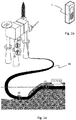
- Fig. 1a illustrates an application and use of a probe for detecting a locally generated corrosion of a metal element when exposing said metal element to a corrosive environment.
- a pipeline 16 leads a hydrocarbon fluid from an oil and gas well.
- a number of probes 1 are placed in proximity to structural elements of the system, which are exposed to a corrosive environment.
- the probe 1 comprises a housing 6 for housing a metal element constituting a first element 2.
- the first element 2 is made of the same material as the structural element, which the probe is proximate to. Alternatively, the first element is made of steel. In this way, a corrosion of the first element is an indication of a corrosion of the structural element.
- the probes are placed in proximity to an underground pipeline, an underwater pipeline, an underwater structural building element and an overwater structural building element.
- Fig. 1b is an enlarged view of the type of probe installed in the four sections I to IV of fig. 1a .
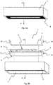
- Fig. 2a is a view of a probe 1 for detecting a locally generated corrosion of a metal element when exposing said metal element to a corrosive environment
- fig. 2b is an exploded view of the probe.
- the metal element constitutes a first element 2.
- the first element is made of a first strip of steel with a width of approximately 0.5 cm, a thickness of approximately 2 mm and a length of approximately 10 cm.
- the first element has a first bend and a second bend for providing a first pair of terminals constituted by a first terminal 9 and a second terminal 10.
- Each of the first and second bends has an angle of 70°, and is approximately 1 cm from each end of the first element.
- the pair of terminals is thus defined by a first terminal at a first end of the first element and a second terminal at a second end of the first element.
- a first pair of electric connectors can be soldered to a respective terminal of the first pair of terminals such that a first electric connector is soldered to the first terminal and a second electric connector is soldered to the second terminal.
- the first element has a first surface 14 constituting an outer surface facing in a first direction, and a second surface 15 constituting an inner surface facing in a second direction, which is opposite to the first direction so that the first and second surfaces are opposite.
- the probe has a housing 6.
- the housing is rectangular with a width of approximately 2 cm, a height of approximately 3 cm and a length of approximately 15 cm.
- the housing has an opening 7.
- the probe also has a second element 4.
- the second element is made of a steel foil with a width of approximately 0.3 cm so that it is less wide than the width of the first element, a thickness of approximately 0.1 mm and a length of approximately 8 cm so that it is not longer than the distance between the bends of the first element.
- the steel foil is cut so that a foil terminal protrudes from the rest of steel foil at approximately the centre of the steel foil.
- the foil terminal constitutes a back terminal 11.
- the back terminal 11 is bent at an angle of approximately 90° so that it faces away from the opening 7 towards the interior of the housing 6.
- a second element wire can be soldered to the back terminal 11.
- the second element wire establishing a connection to a first analyzing unit 18.
- the second element 4 is accommodated in a sponge 3 made of a laboratory grade filter paper with a pore size of 6 ⁇ m and a thickness of 0.2 mm.
- the sponge 3 has a length corresponding to the length of the second element, a width approximately twice the width of the second element.
- the sponge is folded along the length for sandwiching the second element 4 between a top layer 3a of the sponge and a bottom layer 3b of the sponge 3.
- the top layer 3a of the sponge is adjacent the second surface 15 of the first element 2 so that the top layer 3a of the sponge 3 is sandwiched between the first element 2 and the second element 4.
- the probe 1 has a third element 5 made of a second strip of steel with a width of approximately 0.5 cm, a thickness of approximately 2 mm and a length of approximately 10 cm, so that the difference between the dimensions of the first element 2 and the third element 5 is less than 20 %, when the first element has not yet been exposed to a corroding environment.
- the third element 5 has a third bend and a fourth bend for providing a second pair of terminals constituted by a third terminal 12 and a fourth terminal 13.
- Each of the third and fourth bends has an angle of 80° so that the angles are greater than the angles of the bends on the first element.
- the third and fourth bends are approximately 1 cm from each end of the third element.
- a second pair of electric connectors can be soldered to a respective terminal of the second pair of terminals such that a third electric connector is soldered to the third terminal 12 and a fourth electric connector is soldered to the fourth terminal 13.
- the third element 5 is adjacent the bottom layer 3b of the sponge 3 so that the bottom layer of the sponge is sandwiched between the second element 4 and the third element 5.
- the second pair of terminals extends in a direction away from the opening 7 towards the interior of the housing 6.
- Fig. 3a illustrates the B-B' cross section in fig. 2a and fig. 3b illustrates the A-A' cross section in fig. 2b .
- the sponge 3 accommodates the second element 4 and surrounds the second element 4 on three sides.
- the probe 1 is a layered structure comprising the first element 2, the top layer 3a of the sponge, the second element 4, the bottom layer 3b of the sponge and the third element 5.
- the first element 2 is in an opening 7 in a housing 6 so that the first surface 14 is exposed to an environment surrounding the housing.
- the first pair of terminals extends in a direction away from the opening towards the interior of the housing.
- An electrical insulator 8 in the form of an epoxy is between the first element 2 and the housing 6, i.e. between the perimeter of the first element and the perimeter of the housing so that the opening is closed by the first element and the epoxy.
- the epoxy is an electric insulator and does not corrode as fast as the first element.
- the epoxy surrounds the layered structure inside the housing so that only the first surface 14 is exposed to the environment surrounding the housing and so that the layered structure is fixed to the housing.
- the first pair of terminals, second pair of terminals and back terminal extend out from the epoxy.
- Fig. 4a is a view of a probe for detecting a locally generated corrosion of a metal element when exposing said metal element to a corrosive environment
- fig. 4b is an exploded view of the probe.
- the metal element constitutes a first element 2.
- the first element 2 is made of a first strip of steel with a width of approximately 0.5 cm, a thickness of approximately 2 mm and a length of approximately 8 cm.
- the first element 2 has a first surface 14 constituting an outer surface facing in a first direction, and a second surface 15 constituting an inner surface facing in a second direction, which is opposite to the first direction so that the first and second surfaces are opposite.
- the first element 2 has a first end and a second end, which constitute a first pair of terminals.
- a first pair of electric connectors can be soldered to a respective terminal of a first pair of terminals such that a first electric connector is soldered to a first terminal and a second electric connector is soldered to a second terminal.
- the probe has a housing 6.
- the housing is cylindrical with a diameter of approximately 4 cm, and a length of approximately 20 cm.
- the housing has a conical shape at a first end and a lid at a second end.
- the housing has an opening 7.
- the opening is rectangular with a length of approximately 7 cm and a width of approximately 0.4 cm so that the opening is smaller than the first element 2.
- the probe has a second element 4.
- the second element is made of steel and has the shape of a half cylinder.
- the second element has a length of approximately 18 cm, a width of approximately 3 cm and a height of approximately 1.5 cm so that it fits inside the housing.
- a sponge 3 made of a laboratory grade filter paper is on the second element.
- the sponge extend on the convex surface of the second element until 0.5 cm from the edges of the second element.
- the probe has a third element 5 made of a second strip of steel with a width of approximately 0.5 cm, a thickness of approximately 2 mm and a length of approximately 8 cm so that the difference between the dimensions of the first element and the third element is less than 20 % when the first element has not yet been exposed to a corroding environment.
- the third element 5 has a third end and a fourth end, which constitute a second pair of terminals.
- a second pair of electric connectors can be soldered to a respective terminal of the second pair of terminals such that a third electric connector is soldered to a third terminal and a fourth electric connector is soldered to a fourth terminal.
- a second element wire can be soldered to the second element for establishing a connection to a first analyzing unit 18.
- the first element 2 is on the sponge 3 and extend in the longitudinal direction of the sponge.
- the first element is followed by the third element 5 with the second end of the first element being adjacent to third end of the third element.
- the first element 2 is in the opening 7 of the housing 6 so that the first surface is exposed to an environment surrounding the housing.
- the housing seals the inside from the outside of the housing.
- the housing is an electric insulator which together with the first element encapsulates the second element and the sponge for preventing the second element and the sponge from being directly exposed to the outside environment.
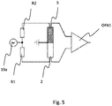
- Fig. 5 shows the first element 2 and the third element 5 in a bridge circuit.
- the circuit comprises a first current generator 19a for supplying a first AC current at a frequency of approximately 1 kHz.
- the first AC current is split into two equal excitation currents in the first pair of electrical connectors and the second pair of electrical connectors (in fig. 5 the return path is illustrated as a ground connection, i.e. the first connector is connected to the first terminal of the first element via a first resistor R1 and current returns via the second connector connected to the second terminal.
- the third connector is connected to the third terminal of the third element via a second resistor R2 and current returns via the fourth connector connected to the fourth terminal.)
- the first and second resistors R1 and R2 provide electrical resistance, which differ by less than 10 %.
- the resistance of the first resistor is 10 K ⁇ and the resistance of the second resistor is 10 K ⁇ so that the resistance of the first and second resistors R1 and R2 are much larger than the resistance of the first element and the resistance of the third element. This means that the excitation current will be substantially evenly distributed through the first and second resistors R1 and R2, even if the resistance of the first element and the resistance of the third element is changing.
- the excitation current induces a first voltage across the first element and a second voltage across the third element. A subtraction of the first and second voltage constitutes a voltage difference.
- a differential amplifier OPA1 is connected to the first terminal and the fourth terminal and amplifies the differential voltage.
- Fig. 6 shows the first element 2 and the third element 5 in a bridge circuit, which in addition to the bridge circuit in fig. 5 has a second amplifier OPA2 and a third amplifier OPA3 for amplifying the voltage across the first element 2 and the third element 5 respectively. Furthermore, the bridge circuit in fig. 6 has a second current generator 19b for supplying a second AC current at a frequency of approximately 2 kHz, so that the frequency of first AC current and the frequency of the second AC current are different.
- the second AC current is split into two excitation currents in a fifth connector and a sixth connector.
- the fifth connector is connected to the first terminal of the first element via a first potentiometer P1.
- the fifth connector is connected to the fourth terminal of the third element via a second potentiometer P2.
- the first potentiometer and the second potentiometers both having a range of 100 ⁇ to 10 K ⁇ .
- the value of the first potentiometer and/or the second potentiometer may be adjusted until the initial resistance difference is zero.
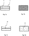
- Fig. 7a illustrates the first element 2 and the second element 4 seen from the side before the first element has been exposed to a corroding environment
- fig. 7b illustrates the first element and the second element seen from above in a direction towards the first surface defining an exposed outer surface to be exposed to a corrosive environment.
- Fig. 7c illustrates the first element and the second element seen from the side after the first element has been exposed to a corroding environment.
- Corrosion is a process, which converts a refined metal such as steel to a more chemically-stable form, such as its oxide, hydroxide, or sulfide. It is the gradual destruction of the steel by a chemical and/or an electrochemical reaction with the environment. Especially under water or under ground, the environment can be seen as an electrolyte solution, which conducts electric charges and chemically reacts with the first element. In general, the more ions there are in the electrolyte solution, the more conductive the electrolyte solution becomes.
- the corrosion may be uniform across the first surface of the first element and/or it may only be a pinhole 20 as described further in the next paragraph regarding fig. 7c .
- the resistance is inverse proportional to the thickness of the first element, which means that the resistance increases as the thickness decreases.
- the first element has been exposed to a corroding environment in a time period (from initial exposure to a penetration time t p ) so that the first element has started to corrode and a local corrosion has created a pinhole 20 down to the second element exposing the second element to the corrosive environment.
- This is also called pitting corrosion, or pitting, which is a form of extremely localized corrosion that leads to the creation of small holes in the metal.
- the driving power for pitting corrosion is the depassivation of a small area, which becomes anodic while an unknown but potentially vast area becomes cathodic, leading to very localized galvanic corrosion.
- the corrosion penetrates the mass of the metal, with a limited diffusion of ions.
- Fig. 7d illustrates a top view of the first element and the second element shown in fig. 7c .
- the first element and the second element is seen from above in a direction towards the first surface after the first element has been exposed to a corroding environment.
- Fig. 8a is a measurement of the voltage V between the first terminal 9 and the second terminal 10 of the first element 2 shown in fig. 2a as a function of time t.
- Four different stages of corrosion of the first element is illustrated in figs. 8b-8e corresponding to the first element 2 and second element 4 seen at times 0, 1, 2, 3 in fig. 8a .
- the first element experiences a corrosion, which is illustrated by the thickness of the first element at time 1 is less than at time 0. This results in an increased resistance of the first element.
- the increased resistance results in an increased voltage over the first element (between the first terminal and the second terminal).
- a local corrosion of the first element has created a pinhole 20 in the first element so that the second element has become directly exposed to the environment.
- Current in the first element can be lead through the wetted sponge, through the second element and back through the wetted sponge into the first element. Effectively, the wetted sponge and the second element establishes a shunt, in which current is allowed to pass through.
- the resistance between the first terminal and the second terminal suddenly becomes lower, which results in a decreased voltage between the first terminal and the second terminal.
- the second element Since the second element has become exposed to the environment at time 2, it starts to corrode, which is illustrated at time 3 by a part of the second element being corroded. As this happens, the shunt becomes less effective and the voltage starts to go up again.
- Fig. 9 is a view of a system for detecting a locally generated corrosion of a metal element when exposing said metal element to a corrosive environment.
- the metal element 2 is in the probe shown in fig. 6 , which is proximate to a pipeline 16.
- a first cable comprises a number of wires for connecting the probe 1 with a first analyzing unit 18.
- a second cable connects a ground electrode 17 with the first analyzing unit.
- a third cable connects the pipeline 16 with the first analyzing unit 18.
- the first analyzing unit comprises an AC voltmeter for measuring voltage and current between terminals.
- the magnitude of the impedance between terminals is the ratio between voltage and current and the phase of the impedance is the phase between the voltage and the current.
- the first analyzing unit can measure the impedance between the ground electrode and the pipeline, the first element and the second element respectively.
- the first analyzing unit can also measure the impedance between the pipeline and the first element and the second element respectively.
- the first analyzing unit comprises a power source for providing an AC current between the second element and the ground electrode.
- the AC current has a frequency of approximately 1 kHz so that noise from example power lines in the vicinity of the pipeline influences the measurement as little as possible.
- Fig. 10a is a measurement of the impedance R between the ground electrode shown in fig. 9 and the second element of the probe shown in fig. 9 as a function of time t.
- Four different stages of corrosion of the first element is illustrated in figs. 10b-10e corresponding to the probe (first element and second element) seen at times 0, 1, 2, 3 in fig. 10a .
- the impedance between the ground electrode and the second element is infinite, which in praxis means at least 2 M ⁇ .
- the first element experiences a corrosion, which is illustrated by the thickness of the first element at time 1 is less than at time 0.
- the impedance between the ground electrode and the second element is still infinite, because even though the first element is corroded, the corrosion has not penetrated the first element.
- a local corrosion of the first element has created a pinhole in the first element so that the second element has become directly exposed to the environment. Current can therefore pass through the pinhole.
- the pinhole is approximately 1 mm wide.
- the impedance falls to a finite value of approximately 1 K ⁇ .
- the impedance is proportional to the size of the pinhole. The wider the pinhole, the lower is the impedance. Since the second element has become exposed to the environment at time 2, it starts to corrode, which is illustrated at time 3 by a part of the second element being corroded.
Landscapes
- Life Sciences & Earth Sciences (AREA)
- Biodiversity & Conservation Biology (AREA)
- Ecology (AREA)
- Environmental & Geological Engineering (AREA)
- Environmental Sciences (AREA)
- Physics & Mathematics (AREA)
- Health & Medical Sciences (AREA)
- Chemical & Material Sciences (AREA)
- Analytical Chemistry (AREA)
- Biochemistry (AREA)
- General Health & Medical Sciences (AREA)
- General Physics & Mathematics (AREA)
- Immunology (AREA)
- Pathology (AREA)
- Testing Resistance To Weather, Investigating Materials By Mechanical Methods (AREA)
Claims (14)
- Procédé de détection d'une corrosion générée localement d'un élément métallique lorsque cet élément métallique est exposé à un environnement corrosif, comprenant:l'approvisionnement d'un élément métallique constituant un premier élément (2) définissant des première et deuxième surfaces opposées (14, 15), ladite première surface (14) définissant une surface extérieure exposée, à être exposée audit environnement corrosif, ledit premier élément (2) comprenant une première paire de bornes (9, 10),l'approvisionnement d'une première paire de connecteurs électriques, et contactant chaque connecteur de ladite première paire de connecteurs électriques avec une borne respective de ladite première paire de bornes (9, 10) pour permettre une injection d'un courant électrique dans ledit premier élément (2),l'approvisionnement d'une éponge (3), ladite éponge (3) constituant à l'état sec un isolant électrique et constituant un conducteur électrique lorsque mouillé dans ledit environnement corrosif, et appliquer ladite éponge (3) à ladite deuxième surface (15) dudit premier élément (2),l'approvisionnement d'un deuxième élément (4) d'un matériau électriquement conducteur, et l'agencement dudit deuxième élément (4) à l'opposé de ladite deuxième surface (15) dudit premier élément (2), et placer ladite éponge (3) entre ledit premier élément (2) et ledit deuxième élément (4),l'approvisionnement d'un isolant électrique (8), ledit isolant électrique (8) encapsulant avec ledit premier élément (2) ledit deuxième élément (4) et ladite éponge (3) pour empêcher ledit deuxième élément (4) et ladite éponge (3) d'être directement exposés audit environnement corrosif,caractérisé par l'injection d'un courant électrique spécifique dans ledit premier élément (2) par l'intermédiaire de ladite première paire de connecteurs électriques, et la mesure d'une tension entre les bornes de ladite première paire de bornes (9, 10), et la surveillance d'une augmentation progressive de ladite tension en raison d'une corrosion dudit premier élément (2), etla détection d'une diminution de ladite tension à cause d'un orifice (20) étant généré dans ledit premier élément (2), causant à ladite éponge (3) d'être mouillée et permettant audit deuxième élément (4) de fournir un shunt par rapport audit premier élément (2), réduisant ainsi une résistance entre les bornes de ladite première paire de bornes (9, 10).
- Procédé de détection d'une corrosion générée localement d'un élément métallique lorsque cet élément métallique est exposé à un environnement corrosif, comprenant:l'approvisionnement dudit élément métallique constituant un premier élément (2) définissant des première et deuxième surfaces opposées (14, 15), ladite première surface (14) définissant une surface extérieure exposée à être exposée audit environnement corrosif, ledit premier élément (2) comprenant une première paire de bornes (9, 10),l'approvisionnement d'une première paire de connecteurs électrique, et contactant chaque connecteur de ladite première paire de connecteurs électriques avec une borne respective de ladite première paire de bornes (9, 10) pour permettre une injection d'un courant électrique dans ledit premier élément (2),l'approvisionnement d'une éponge (3), ladite éponge (3) constituant à l'état sec un isolant électrique et constituant un conducteur électrique lorsque mouillé dans ledit environnement corrosif, et l'application de ladite éponge (3) à ladite deuxième surface (15) dudit premier élément (2),l'approvisionnement d'un deuxième élément (4) d'un matériau électriquement conducteur, et l'agencement dudit deuxième élément (4) à l'opposé de ladite deuxième surface (15) dudit premier élément (2), et placant ladite éponge (3) entre ledit premier élément (2) et ledit deuxième élément (4),l'approvisionnement d'un isolant électrique (8), ledit isolant électrique (8) encapsulant avec ledit premier élément (2) ledit deuxième élément (4) et ladite éponge (3) pour empêcher ledit deuxième élément (4) et ladite éponge (3) d'être directement exposés audit environnement corrosif,caractérisé par la mesure d'une impédance entre ledit deuxième élément (4) et une électrode de terre (17), et la surveillance d'une diminution de ladite impédance d'une impédance infinie à une impédance finie causée par un orifice (20) étant généré dans ledit premier élément (2), causant à ladite éponge (3) d'être mouillée et à un chemin de conduction électrique d'être établi entre ledit deuxième élément (4) et ladite électrode de terre (17).
- Système de détection d'une corrosion générée localement d'un élément métallique lorsque cet élément métallique est exposé à un environnement corrosif, ledit système comprenant ledit élément métallique,où ledit élément métallique constitue un premier élément (2) définissant des première et deuxième surfaces opposées (14, 15), ladite première surface (14) définissant une surface extérieure exposée, à être exposée à un environnement corrosif, ledit premier élément (2) comprenant une première paire de bornes (9, 10),ledit système comprenant en outre une première paire de connecteurs électriques, où chaque connecteur de ladite première paire de connecteurs électriques est connecté à une borne respective de ladite première paire de bornes (9, 10) pour permettre une injection d'un courant électrique dans ledit premier élément (2),une éponge (3), ladite éponge (3) constituant à l'état sec un isolant électrique et constituant un conducteur électrique lorsque mouillé dans ledit environnement corrosif,où ladite éponge (3) est juxtaposée ladite deuxième surface (15) dudit premier élément (2),un deuxième élément (4) d'un matériau électriquement conducteur,où ledit deuxième élément (4) se situe à l'opposé de ladite deuxième surface (15) dudit premier élément (2) et où ladite éponge (3) est placée entre ledit premier élément (2) et ledit deuxième élément (4),un isolant électrique (8), ledit isolant électrique (8) encapsulant avec ledit premier élément (2) ledit deuxième élément (4) et ladite éponge (3) pour empêcher ledit deuxième élément (4) et ladite éponge (3) d'être directement exposés audit environnement corrosif,caractérisé en ce que le système comprend en outreun générateur de courant configuré pour injecter un courant électrique spécifique dans ledit premier élément (2) par l'intermédiaire de ladite première paire de connecteurs électriques (9, 10),un voltmètre configuré pour mesurer une tension entre les bornes de ladite première paire de bornes (9, 10), et surveillant l'augmentation progressive de ladite tension dûe à la corrosion dudit premier élément (2), etune unité d'analyse configurée pour détecter la diminution de ladite tension causée par un orifice (20) étant généré dans ledit premier élément (2), causant à ladite éponge (3) d'être mouillée et permettant audit deuxième élément (4) de fournir un shunt par rapport audit premier élément (2), réduisant ainsi la résistance entre les bornes de ladite première de bornes (9, 10).
- Système de détection d'une corrosion générée localement d'un élément métallique lorsque cet élément métallique est exposé à un environnement corrosif, ledit système comprenant ledit élément métallique,où ledit élément métallique constitue un premier élément (2) définissant des première et deuxième surfaces opposées (14, 15), ladite première surface (14) définissant une surface extérieure exposée, à être exposée à un environnement corrosif, ledit premier élément (2) comprenant une première paire de bornes (9, 10),ledit système comprenant en outre une première paire de connecteurs électriques, où chaque connecteur de ladite première paire de connecteurs électriques est connecté à une borne respective de ladite première paire de bornes (9, 10) pour permettre une injection d'un courant électrique dans ledit premier élément (2),une éponge (3), ladite éponge (3) constituant à l'état sec un isolant électrique et constituant un conducteur électrique lorsque mouillé dans ledit environnement corrosif,où ladite éponge (3) est juxtaposée ladite deuxième surface (15) dudit premier élément (2),un deuxième élément (4) d'un matériau électriquement conducteur,où ledit deuxième élément (4) se situe à l'opposé de ladite deuxième surface (15) dudit premier élément (2) et où ladite éponge (3) est placée entre ledit premier élément (2) et ledit deuxième élément (4),un isolant électrique (8), ledit isolant électrique (8) encapsulant avec ledit premier élément (2) ledit deuxième élément (4) et ladite éponge (3) pour empêcher ledit deuxième élément (4) et ladite éponge (3) d'être directement exposés audit environnement corrosif,caractérisé en ce que le système comprend en outreun générateur de courant configuré pour injecter un courant électrique spécifique dans ledit premier élément (2) par l'intermédiaire de ladite première paire de connecteurs électriques,un voltmètre configuré pour mesurer une tension entre les bornes de ladite première paire de bornes (9, 10), et surveillant une augmentation progressive de ladite tension dûe à la corrosion dudit premier élément (2), etune unité de mesure configurée pour mesurer une impédance entre ledit deuxième élément (2) et une électrode de terre (17) etune unité d'analyse configurée pour surveiller une diminution de ladite impédance d'une impédance infinie à une impédance finie causée par un orifice (20) étant généré dans ledit premier élément (2), causant à ladite éponge (3) d'être mouillée et à un chemin de conduction électrique d'être établi entre ledit deuxième élément (4) et ladite électrode de terre (17).
- Procédé selon la revendication 2, où ledit deuxième élément (4) comprend une borne arrière (11).
- Procédé selon la revendication 5, comprenant
l'approvisionnement d'un troisième connecteur, et contactant ledit troisième connecteur avec ladite borne arrière (11) afin de mesurer ladite impédance entre ledit deuxième élément (2) et ladite électrode de terre (17). - Procédé selon la revendication 1 ou la revendication 2, comprenant
l'approvisionnement d'un troisième élément (5) d'un métal pour définir une référence de température par rapport au premier élément (2), ledit troisième élément (5) étant encapsulé pour empêcher l'exposition audit environnement corrosif. - Procédé selon la revendication 7, où ledit troisième élément (5) comprend une deuxième paire de bornes (12, 13).
- Procédé selon la revendication 8, comprenant:
l'approvisionnement d'une deuxième paire de connecteurs éléctriques, et contactant chaque connecteur de ladite deuxième paire de connecteurs électriques avec une borne respective de ladite deuxième paire de bornes (12, 13) pour permettre une injection d'un courant électrique dans ledit troisième élément (5). - Procédé selon la revendication 9, comprenant:
l'injection d'un courant électrique spécifique dans ledit troisième élément (5) par ladite deuxième paire de connecteurs électriques, et la mesure d'une tension entre les bornes de ladite deuxième de bornes (12, 13). - Procédé selon la revendication 10, comprenant:
la comparaison de ladite tension entre les bornes de ladite première paire de bornes (9, 10) avec ladite tension entre les bornes de ladite deuxième paire de bornes (12, 13) pour déteminer une polarisation de tension dudit premier élément (2). - Procédé selon l'une quelconque des revendications 1 ou 2, comprenant la détemination d'une épaisseur du premier élément en fonction dudit courant électrique spécifique et ladite tension entre les bornes de ladite première paire de bornes (9, 10).
- Procédé selon l'une quelconque des revendications 1 ou 2, où ladite éponge (3) est faite d'un papier filtre de laboratoire.
- Procédé selon l'une quelconque des revendications 1 ou 2, où ledit isolant électrique (8) est un époxy.
Applications Claiming Priority (2)
| Application Number | Priority Date | Filing Date | Title |
|---|---|---|---|
| EP17159834.5A EP3372987A1 (fr) | 2017-03-08 | 2017-03-08 | Procédé de détection de la corrosion générée localement d'un élément métallique |
| PCT/EP2018/055475 WO2018162483A1 (fr) | 2017-03-08 | 2018-03-06 | Procédé de détection de la corrosion générée localement d'un élément métallique |
Publications (2)
| Publication Number | Publication Date |
|---|---|
| EP3593115A1 EP3593115A1 (fr) | 2020-01-15 |
| EP3593115B1 true EP3593115B1 (fr) | 2021-05-05 |
Family
ID=58397995
Family Applications (2)
| Application Number | Title | Priority Date | Filing Date |
|---|---|---|---|
| EP17159834.5A Withdrawn EP3372987A1 (fr) | 2017-03-08 | 2017-03-08 | Procédé de détection de la corrosion générée localement d'un élément métallique |
| EP18707931.4A Active EP3593115B1 (fr) | 2017-03-08 | 2018-03-06 | Procédé de détection de la corrosion générée localement d'un élément métallique |
Family Applications Before (1)
| Application Number | Title | Priority Date | Filing Date |
|---|---|---|---|
| EP17159834.5A Withdrawn EP3372987A1 (fr) | 2017-03-08 | 2017-03-08 | Procédé de détection de la corrosion générée localement d'un élément métallique |
Country Status (4)
| Country | Link |
|---|---|
| US (1) | US11262291B2 (fr) |
| EP (2) | EP3372987A1 (fr) |
| DK (1) | DK3593115T3 (fr) |
| WO (1) | WO2018162483A1 (fr) |
Family Cites Families (7)
| Publication number | Priority date | Publication date | Assignee | Title |
|---|---|---|---|---|
| WO2001042764A2 (fr) | 1999-12-10 | 2001-06-14 | Vn-Instrument I/S | Procede et appareil pour mesurer un taux cumule et immediat d'une perte materielle ou d'un gain materiel |
| EP1571438A1 (fr) | 2004-03-01 | 2005-09-07 | MetriCorr ApS | Procédé et système de diagnostic du risque d'oxydation d'un tuyau ou d'une canalisation dans le sol |
| CH697044A5 (de) * | 2004-06-09 | 2008-03-31 | Markus Buechler | Messprobe zur Bestimmung der Korrosionsangriffstiefe. |
| US7388386B2 (en) * | 2006-03-31 | 2008-06-17 | General Electric Company | Method and apparatus for corrosion detection |
| EP2124034A1 (fr) * | 2008-05-20 | 2009-11-25 | BAE Systems PLC | Capteurs de corrosion |
| JP5942349B2 (ja) * | 2011-07-07 | 2016-06-29 | セイコーエプソン株式会社 | センサー装置 |
| ITMI20130484A1 (it) * | 2013-03-29 | 2014-09-30 | St Microelectronics Srl | Dispositivo elettronico integrato per il monitoraggio di umidita' e/o acidita'/basicita' ambientali e/o corrosione |
-
2017
- 2017-03-08 EP EP17159834.5A patent/EP3372987A1/fr not_active Withdrawn
-
2018
- 2018-03-06 EP EP18707931.4A patent/EP3593115B1/fr active Active
- 2018-03-06 DK DK18707931.4T patent/DK3593115T3/da active
- 2018-03-06 WO PCT/EP2018/055475 patent/WO2018162483A1/fr not_active Ceased
- 2018-03-06 US US16/491,877 patent/US11262291B2/en active Active
Also Published As
| Publication number | Publication date |
|---|---|
| US20200041403A1 (en) | 2020-02-06 |
| EP3372987A1 (fr) | 2018-09-12 |
| WO2018162483A1 (fr) | 2018-09-13 |
| DK3593115T3 (da) | 2021-08-09 |
| EP3593115A1 (fr) | 2020-01-15 |
| US11262291B2 (en) | 2022-03-01 |
Similar Documents
| Publication | Publication Date | Title |
|---|---|---|
| US6894502B2 (en) | pH sensor with internal solution ground | |
| US4481474A (en) | Device for measurement of the potential with respect to the soil of a cathodically protected metallic structure | |
| US4861453A (en) | Corrosion detecting probe for steel buried in concrete | |
| US9335287B2 (en) | Specification device for water status of soil, and method for same | |
| US5712559A (en) | Cathodic protection reference cell and corrosion sensor | |
| US7508223B1 (en) | Multihole and multiwire sensors for localized and general corrosion monitoring | |
| US3649492A (en) | Method for determining the completeness of cathodic protection of corrodible metal structure | |
| JP4137058B2 (ja) | 腐食・防食状態評価方法 | |
| WO2004097906A2 (fr) | Electrode de reference semi-permanente | |
| US7388386B2 (en) | Method and apparatus for corrosion detection | |
| EP3862465B1 (fr) | Électrode de référence permanente sur gel de cuivre/de sulfate de cuivre pour la mesure du potentiel réel et de la densité de courant de structures métalliques enfouies | |
| JP2001215203A (ja) | 電気伝導度測定装置、土壌導電率測定方法及び土壌溶液導電率測定装置 | |
| JPS59132354A (ja) | パイプラツプ被膜の非破壊的陰極分離試験方法及び装置 | |
| EP2277033B1 (fr) | Dispositif de mesure pour mesurer des propriétés électriques d'échantillons géologiques solides ou liquides | |
| CN111788478A (zh) | 腐蚀测量装置 | |
| KR102143685B1 (ko) | 토양의 전기 전도도 측정 장치 | |
| US11262291B2 (en) | Method of detecting the locally generated corrosion of a metal element | |
| EP0441659A1 (fr) | Détection d'une fissure dans la paroi d'un capteur électrochimique | |
| RU2471171C1 (ru) | Устройство для оценки защищенности от коррозии по величине смещения от естественного потенциала | |
| US3549993A (en) | Corrosion rate measuring method by maintaining electrolytic contact and excluding any substantial oxygen contact with a test specimen | |
| CN216082580U (zh) | 一种管道涂层老化状态监测探头 | |
| RU2748862C2 (ru) | Система мониторинга герметичности гидроизоляционного слоя кровли | |
| RU90204U1 (ru) | Устройство для контроля защищенности подземных металлических сооружений | |
| RU2143107C1 (ru) | Устройство для контроля степени локальной коррозии металлических сооружений | |
| RU237047U1 (ru) | Комбинированный сенсор скорости коррозии |
Legal Events
| Date | Code | Title | Description |
|---|---|---|---|
| STAA | Information on the status of an ep patent application or granted ep patent |
Free format text: STATUS: UNKNOWN |
|
| STAA | Information on the status of an ep patent application or granted ep patent |
Free format text: STATUS: THE INTERNATIONAL PUBLICATION HAS BEEN MADE |
|
| PUAI | Public reference made under article 153(3) epc to a published international application that has entered the european phase |
Free format text: ORIGINAL CODE: 0009012 |
|
| STAA | Information on the status of an ep patent application or granted ep patent |
Free format text: STATUS: REQUEST FOR EXAMINATION WAS MADE |
|
| 17P | Request for examination filed |
Effective date: 20191008 |
|
| AK | Designated contracting states |
Kind code of ref document: A1 Designated state(s): AL AT BE BG CH CY CZ DE DK EE ES FI FR GB GR HR HU IE IS IT LI LT LU LV MC MK MT NL NO PL PT RO RS SE SI SK SM TR |
|
| AX | Request for extension of the european patent |
Extension state: BA ME |
|
| DAV | Request for validation of the european patent (deleted) | ||
| DAX | Request for extension of the european patent (deleted) | ||
| STAA | Information on the status of an ep patent application or granted ep patent |
Free format text: STATUS: EXAMINATION IS IN PROGRESS |
|
| 17Q | First examination report despatched |
Effective date: 20200820 |
|
| GRAP | Despatch of communication of intention to grant a patent |
Free format text: ORIGINAL CODE: EPIDOSNIGR1 |
|
| STAA | Information on the status of an ep patent application or granted ep patent |
Free format text: STATUS: GRANT OF PATENT IS INTENDED |
|
| INTG | Intention to grant announced |
Effective date: 20201127 |
|
| GRAS | Grant fee paid |
Free format text: ORIGINAL CODE: EPIDOSNIGR3 |
|
| GRAA | (expected) grant |
Free format text: ORIGINAL CODE: 0009210 |
|
| STAA | Information on the status of an ep patent application or granted ep patent |
Free format text: STATUS: THE PATENT HAS BEEN GRANTED |
|
| AK | Designated contracting states |
Kind code of ref document: B1 Designated state(s): AL AT BE BG CH CY CZ DE DK EE ES FI FR GB GR HR HU IE IS IT LI LT LU LV MC MK MT NL NO PL PT RO RS SE SI SK SM TR |
|
| REG | Reference to a national code |
Ref country code: GB Ref legal event code: FG4D |
|
| REG | Reference to a national code |
Ref country code: CH Ref legal event code: EP |
|
| REG | Reference to a national code |
Ref country code: AT Ref legal event code: REF Ref document number: 1390412 Country of ref document: AT Kind code of ref document: T Effective date: 20210515 |
|
| REG | Reference to a national code |
Ref country code: IE Ref legal event code: FG4D |
|
| REG | Reference to a national code |
Ref country code: DE Ref legal event code: R096 Ref document number: 602018016617 Country of ref document: DE |
|
| REG | Reference to a national code |
Ref country code: DK Ref legal event code: T3 Effective date: 20210804 |
|
| REG | Reference to a national code |
Ref country code: LT Ref legal event code: MG9D |
|
| REG | Reference to a national code |
Ref country code: AT Ref legal event code: MK05 Ref document number: 1390412 Country of ref document: AT Kind code of ref document: T Effective date: 20210505 |
|
| PG25 | Lapsed in a contracting state [announced via postgrant information from national office to epo] |
Ref country code: HR Free format text: LAPSE BECAUSE OF FAILURE TO SUBMIT A TRANSLATION OF THE DESCRIPTION OR TO PAY THE FEE WITHIN THE PRESCRIBED TIME-LIMIT Effective date: 20210505 Ref country code: LT Free format text: LAPSE BECAUSE OF FAILURE TO SUBMIT A TRANSLATION OF THE DESCRIPTION OR TO PAY THE FEE WITHIN THE PRESCRIBED TIME-LIMIT Effective date: 20210505 Ref country code: FI Free format text: LAPSE BECAUSE OF FAILURE TO SUBMIT A TRANSLATION OF THE DESCRIPTION OR TO PAY THE FEE WITHIN THE PRESCRIBED TIME-LIMIT Effective date: 20210505 Ref country code: BG Free format text: LAPSE BECAUSE OF FAILURE TO SUBMIT A TRANSLATION OF THE DESCRIPTION OR TO PAY THE FEE WITHIN THE PRESCRIBED TIME-LIMIT Effective date: 20210805 Ref country code: AT Free format text: LAPSE BECAUSE OF FAILURE TO SUBMIT A TRANSLATION OF THE DESCRIPTION OR TO PAY THE FEE WITHIN THE PRESCRIBED TIME-LIMIT Effective date: 20210505 |
|
| PG25 | Lapsed in a contracting state [announced via postgrant information from national office to epo] |
Ref country code: GR Free format text: LAPSE BECAUSE OF FAILURE TO SUBMIT A TRANSLATION OF THE DESCRIPTION OR TO PAY THE FEE WITHIN THE PRESCRIBED TIME-LIMIT Effective date: 20210806 Ref country code: IS Free format text: LAPSE BECAUSE OF FAILURE TO SUBMIT A TRANSLATION OF THE DESCRIPTION OR TO PAY THE FEE WITHIN THE PRESCRIBED TIME-LIMIT Effective date: 20210905 Ref country code: LV Free format text: LAPSE BECAUSE OF FAILURE TO SUBMIT A TRANSLATION OF THE DESCRIPTION OR TO PAY THE FEE WITHIN THE PRESCRIBED TIME-LIMIT Effective date: 20210505 Ref country code: NO Free format text: LAPSE BECAUSE OF FAILURE TO SUBMIT A TRANSLATION OF THE DESCRIPTION OR TO PAY THE FEE WITHIN THE PRESCRIBED TIME-LIMIT Effective date: 20210805 Ref country code: PL Free format text: LAPSE BECAUSE OF FAILURE TO SUBMIT A TRANSLATION OF THE DESCRIPTION OR TO PAY THE FEE WITHIN THE PRESCRIBED TIME-LIMIT Effective date: 20210505 Ref country code: PT Free format text: LAPSE BECAUSE OF FAILURE TO SUBMIT A TRANSLATION OF THE DESCRIPTION OR TO PAY THE FEE WITHIN THE PRESCRIBED TIME-LIMIT Effective date: 20210906 Ref country code: SE Free format text: LAPSE BECAUSE OF FAILURE TO SUBMIT A TRANSLATION OF THE DESCRIPTION OR TO PAY THE FEE WITHIN THE PRESCRIBED TIME-LIMIT Effective date: 20210505 Ref country code: RS Free format text: LAPSE BECAUSE OF FAILURE TO SUBMIT A TRANSLATION OF THE DESCRIPTION OR TO PAY THE FEE WITHIN THE PRESCRIBED TIME-LIMIT Effective date: 20210505 |
|
| REG | Reference to a national code |
Ref country code: NL Ref legal event code: MP Effective date: 20210505 |
|
| PG25 | Lapsed in a contracting state [announced via postgrant information from national office to epo] |
Ref country code: NL Free format text: LAPSE BECAUSE OF FAILURE TO SUBMIT A TRANSLATION OF THE DESCRIPTION OR TO PAY THE FEE WITHIN THE PRESCRIBED TIME-LIMIT Effective date: 20210505 |
|
| PG25 | Lapsed in a contracting state [announced via postgrant information from national office to epo] |
Ref country code: ES Free format text: LAPSE BECAUSE OF FAILURE TO SUBMIT A TRANSLATION OF THE DESCRIPTION OR TO PAY THE FEE WITHIN THE PRESCRIBED TIME-LIMIT Effective date: 20210505 Ref country code: EE Free format text: LAPSE BECAUSE OF FAILURE TO SUBMIT A TRANSLATION OF THE DESCRIPTION OR TO PAY THE FEE WITHIN THE PRESCRIBED TIME-LIMIT Effective date: 20210505 Ref country code: SK Free format text: LAPSE BECAUSE OF FAILURE TO SUBMIT A TRANSLATION OF THE DESCRIPTION OR TO PAY THE FEE WITHIN THE PRESCRIBED TIME-LIMIT Effective date: 20210505 Ref country code: SM Free format text: LAPSE BECAUSE OF FAILURE TO SUBMIT A TRANSLATION OF THE DESCRIPTION OR TO PAY THE FEE WITHIN THE PRESCRIBED TIME-LIMIT Effective date: 20210505 Ref country code: CZ Free format text: LAPSE BECAUSE OF FAILURE TO SUBMIT A TRANSLATION OF THE DESCRIPTION OR TO PAY THE FEE WITHIN THE PRESCRIBED TIME-LIMIT Effective date: 20210505 Ref country code: RO Free format text: LAPSE BECAUSE OF FAILURE TO SUBMIT A TRANSLATION OF THE DESCRIPTION OR TO PAY THE FEE WITHIN THE PRESCRIBED TIME-LIMIT Effective date: 20210505 |
|
| REG | Reference to a national code |
Ref country code: DE Ref legal event code: R097 Ref document number: 602018016617 Country of ref document: DE |
|
| PLBE | No opposition filed within time limit |
Free format text: ORIGINAL CODE: 0009261 |
|
| STAA | Information on the status of an ep patent application or granted ep patent |
Free format text: STATUS: NO OPPOSITION FILED WITHIN TIME LIMIT |
|
| 26N | No opposition filed |
Effective date: 20220208 |
|
| PG25 | Lapsed in a contracting state [announced via postgrant information from national office to epo] |
Ref country code: IS Free format text: LAPSE BECAUSE OF FAILURE TO SUBMIT A TRANSLATION OF THE DESCRIPTION OR TO PAY THE FEE WITHIN THE PRESCRIBED TIME-LIMIT Effective date: 20210905 Ref country code: AL Free format text: LAPSE BECAUSE OF FAILURE TO SUBMIT A TRANSLATION OF THE DESCRIPTION OR TO PAY THE FEE WITHIN THE PRESCRIBED TIME-LIMIT Effective date: 20210505 |
|
| PG25 | Lapsed in a contracting state [announced via postgrant information from national office to epo] |
Ref country code: IT Free format text: LAPSE BECAUSE OF FAILURE TO SUBMIT A TRANSLATION OF THE DESCRIPTION OR TO PAY THE FEE WITHIN THE PRESCRIBED TIME-LIMIT Effective date: 20210505 |
|
| PG25 | Lapsed in a contracting state [announced via postgrant information from national office to epo] |
Ref country code: MC Free format text: LAPSE BECAUSE OF FAILURE TO SUBMIT A TRANSLATION OF THE DESCRIPTION OR TO PAY THE FEE WITHIN THE PRESCRIBED TIME-LIMIT Effective date: 20210505 |
|
| REG | Reference to a national code |
Ref country code: CH Ref legal event code: PL |
|
| PG25 | Lapsed in a contracting state [announced via postgrant information from national office to epo] |
Ref country code: LU Free format text: LAPSE BECAUSE OF NON-PAYMENT OF DUE FEES Effective date: 20220306 Ref country code: LI Free format text: LAPSE BECAUSE OF NON-PAYMENT OF DUE FEES Effective date: 20220331 Ref country code: IE Free format text: LAPSE BECAUSE OF NON-PAYMENT OF DUE FEES Effective date: 20220306 Ref country code: CH Free format text: LAPSE BECAUSE OF NON-PAYMENT OF DUE FEES Effective date: 20220331 |
|
| PG25 | Lapsed in a contracting state [announced via postgrant information from national office to epo] |
Ref country code: MK Free format text: LAPSE BECAUSE OF FAILURE TO SUBMIT A TRANSLATION OF THE DESCRIPTION OR TO PAY THE FEE WITHIN THE PRESCRIBED TIME-LIMIT Effective date: 20210505 Ref country code: CY Free format text: LAPSE BECAUSE OF FAILURE TO SUBMIT A TRANSLATION OF THE DESCRIPTION OR TO PAY THE FEE WITHIN THE PRESCRIBED TIME-LIMIT Effective date: 20210505 |
|
| PG25 | Lapsed in a contracting state [announced via postgrant information from national office to epo] |
Ref country code: HU Free format text: LAPSE BECAUSE OF FAILURE TO SUBMIT A TRANSLATION OF THE DESCRIPTION OR TO PAY THE FEE WITHIN THE PRESCRIBED TIME-LIMIT; INVALID AB INITIO Effective date: 20180306 |
|
| PG25 | Lapsed in a contracting state [announced via postgrant information from national office to epo] |
Ref country code: MT Free format text: LAPSE BECAUSE OF FAILURE TO SUBMIT A TRANSLATION OF THE DESCRIPTION OR TO PAY THE FEE WITHIN THE PRESCRIBED TIME-LIMIT Effective date: 20210505 |
|
| PG25 | Lapsed in a contracting state [announced via postgrant information from national office to epo] |
Ref country code: TR Free format text: LAPSE BECAUSE OF FAILURE TO SUBMIT A TRANSLATION OF THE DESCRIPTION OR TO PAY THE FEE WITHIN THE PRESCRIBED TIME-LIMIT Effective date: 20210505 |
|
| PGFP | Annual fee paid to national office [announced via postgrant information from national office to epo] |
Ref country code: GB Payment date: 20260317 Year of fee payment: 9 |
|
| PGFP | Annual fee paid to national office [announced via postgrant information from national office to epo] |
Ref country code: DE Payment date: 20260318 Year of fee payment: 9 Ref country code: DK Payment date: 20260325 Year of fee payment: 9 |
|
| PGFP | Annual fee paid to national office [announced via postgrant information from national office to epo] |
Ref country code: BE Payment date: 20260317 Year of fee payment: 9 |
|
| PGFP | Annual fee paid to national office [announced via postgrant information from national office to epo] |
Ref country code: FR Payment date: 20260317 Year of fee payment: 9 |