EP3594411A2 - Structure d'anode pour fondation offshore, et procédé de réduction de la corrosion dans une fondation offshore - Google Patents
Structure d'anode pour fondation offshore, et procédé de réduction de la corrosion dans une fondation offshore Download PDFInfo
- Publication number
- EP3594411A2 EP3594411A2 EP19205690.1A EP19205690A EP3594411A2 EP 3594411 A2 EP3594411 A2 EP 3594411A2 EP 19205690 A EP19205690 A EP 19205690A EP 3594411 A2 EP3594411 A2 EP 3594411A2
- Authority
- EP
- European Patent Office
- Prior art keywords
- anode
- offshore foundation
- surface region
- anode structure
- exposed surface
- Prior art date
- Legal status (The legal status is an assumption and is not a legal conclusion. Google has not performed a legal analysis and makes no representation as to the accuracy of the status listed.)
- Withdrawn
Links
- 238000005260 corrosion Methods 0.000 title claims description 24
- 230000007797 corrosion Effects 0.000 title claims description 10
- 238000000034 method Methods 0.000 title claims description 6
- 230000015572 biosynthetic process Effects 0.000 claims abstract description 32
- 238000005755 formation reaction Methods 0.000 claims abstract description 32
- 239000011248 coating agent Substances 0.000 claims abstract description 13
- 238000000576 coating method Methods 0.000 claims abstract description 13
- 239000000463 material Substances 0.000 claims abstract description 6
- 239000003973 paint Substances 0.000 claims description 6
- 230000013011 mating Effects 0.000 claims description 4
- 239000010405 anode material Substances 0.000 description 8
- 238000009434 installation Methods 0.000 description 5
- 229910000831 Steel Inorganic materials 0.000 description 4
- 239000010959 steel Substances 0.000 description 4
- 230000007704 transition Effects 0.000 description 3
- XLYOFNOQVPJJNP-UHFFFAOYSA-N water Substances O XLYOFNOQVPJJNP-UHFFFAOYSA-N 0.000 description 3
- 238000007689 inspection Methods 0.000 description 2
- 229910000510 noble metal Inorganic materials 0.000 description 2
- 239000000725 suspension Substances 0.000 description 2
- RYGMFSIKBFXOCR-UHFFFAOYSA-N Copper Chemical compound [Cu] RYGMFSIKBFXOCR-UHFFFAOYSA-N 0.000 description 1
- 229910001335 Galvanized steel Inorganic materials 0.000 description 1
- FYYHWMGAXLPEAU-UHFFFAOYSA-N Magnesium Chemical compound [Mg] FYYHWMGAXLPEAU-UHFFFAOYSA-N 0.000 description 1
- HCHKCACWOHOZIP-UHFFFAOYSA-N Zinc Chemical compound [Zn] HCHKCACWOHOZIP-UHFFFAOYSA-N 0.000 description 1
- 229910045601 alloy Inorganic materials 0.000 description 1
- 239000000956 alloy Substances 0.000 description 1
- 238000004210 cathodic protection Methods 0.000 description 1
- 239000004020 conductor Substances 0.000 description 1
- 238000010276 construction Methods 0.000 description 1
- 229910052802 copper Inorganic materials 0.000 description 1
- 239000010949 copper Substances 0.000 description 1
- 230000008878 coupling Effects 0.000 description 1
- 238000010168 coupling process Methods 0.000 description 1
- 238000005859 coupling reaction Methods 0.000 description 1
- 230000000694 effects Effects 0.000 description 1
- 238000004880 explosion Methods 0.000 description 1
- 239000008397 galvanized steel Substances 0.000 description 1
- 230000005484 gravity Effects 0.000 description 1
- 229910052749 magnesium Inorganic materials 0.000 description 1
- 239000011777 magnesium Substances 0.000 description 1
- 238000012423 maintenance Methods 0.000 description 1
- 229910052751 metal Inorganic materials 0.000 description 1
- 239000002184 metal Substances 0.000 description 1
- 238000012544 monitoring process Methods 0.000 description 1
- 239000000843 powder Substances 0.000 description 1
- 239000013535 sea water Substances 0.000 description 1
- 239000000758 substrate Substances 0.000 description 1
- 230000001960 triggered effect Effects 0.000 description 1
- 239000011701 zinc Substances 0.000 description 1
- 229910052725 zinc Inorganic materials 0.000 description 1
Images
Classifications
-
- E—FIXED CONSTRUCTIONS
- E02—HYDRAULIC ENGINEERING; FOUNDATIONS; SOIL SHIFTING
- E02B—HYDRAULIC ENGINEERING
- E02B17/00—Artificial islands mounted on piles or like supports, e.g. platforms on raisable legs or offshore constructions; Construction methods therefor
- E02B17/0017—Means for protecting offshore constructions
- E02B17/0026—Means for protecting offshore constructions against corrosion
Definitions
- the present invention relates to an anode structure for providing cathodic protection from corrosion to the surface of an offshore foundation, and particularly foundations for offshore wind turbines.
- the present invention also relates to an offshore foundation, an assembly, and to a method for minimising corrosion of an offshore foundation using said anode structure.
- foundations installed in the seabed.
- Such foundation structures are commonly monopiles.
- Other example foundations include jackets, suction buckets, floating foundations, gravity-based foundation and other foundation structures known to a person skilled in the art.
- a monopile foundation comprises a body formed of a hollow tube that typically has a conical section. As such, the lower seabed-facing end is wider in diameter than the upper end facing the wind turbine tower.
- the monopile body forms a primary structure.
- a transition piece is commonly used as an interface between the two. The transition piece is connected on a lower side thereof to the monopile and on an upper side thereof to the wind turbine tower.
- the transition piece can, if desired, be provided with additional constructions such as a work platform, a boat landing and other useful applications. These are considered to be secondary structures which are attached to the primary structure once it is installed.
- the monopile is preferably installed by pile driving it into the seabed. It hence sits in the seawater and is thus susceptible to corrosion. In order to make a monopile corrosion-resistant, it is generally coated with corrosion-preventing paint to reduce corrosion. On top of this, it is also common to further provide an anode structure for providing galvanic corrosion protection.
- a common type of anode structure is called an anode cage, which comprises from a plurality of anode tubes arranged around the monopile on a ring-like frame which sits under water in use.
- the anodes are made of a less noble metal than the monopile's body and hence function as sacrificial anodes corroding instead of the monopile.
- the monopile is for this purpose generally provided with suspension points which can only have limited dimensions. Suspension points with oversized dimensions are not desirable because they can affect the fatigue resistance of the monopile and form an obstacle during installation of the monopile.
- the anode cage thus preferably has to be arranged around the monopile with little clearance, and then electrically connected to the monopile using cables.
- ROVs Remotely operated vehicles
- EP3483342 discloses an auxiliary device for positioning and securing an anode cage to a monopile.
- the device can be suspended from a hoisting means using a coupling and can be carried into the vicinity of the primary structure, i.e. the offshore wind turbine foundation.
- the support body of the auxiliary device comprises a number of remotely controlled tools for positioning the secondary structure, i.e. the anode cage, and forming the electrical and mechanical connections between the secondary and primary structures.
- EP3483342 uses an earthing cable connected to the anode cage at one end and to an earthing plate at the other.
- a powder activated tool provided on the auxiliary device may then be triggered to drive the earthing plate into the monopile body under the force of a controlled explosion.
- the earthing cable must have sufficient slack to accommodate the movement required by this direct fixing method.
- the present invention seeks to address the above problems associated with the prior art.
- an anode structure for connection to an offshore foundation having a body with a coated surface region and an exposed surface region without a coating
- the anode structure comprising: one or more anode elements formed of a material having a more negative electrode potential than the body of the offshore foundation; an electrically conductive frame for supporting the one or more anode elements and for attachment to the body of the offshore foundation; wherein the electrically conductive frame comprises one or more electrical contact formations for contacting the exposed surface region when the frame is attached to the body.
- the present invention thereby allows the anode structure to be electrically connected directly to the foundation body, without requiring separate connection cables. This provides for more straightforward installation and a more reliable earthing connection between the structures.
- the present invention also avoids or minimises the need to employ divers or ROVs devices to install the anode structure.
- the anode structure is an anode cage.
- the offshore foundation is a monopile.
- the coated surface region is coated with an anti-corrosion coating. More preferably, the anti-corrosion coating is an anti-corrosion paint.
- the one or more electrical contact formations comprise a plurality of electrical contact formations for contacting the exposed surface region.
- the electrical contact formations project inward from the electrically conductive frame.
- the electrical contact formations are provided on an upper ring of the electrically conductive frame.
- the body of the offshore foundation comprises a conical section
- the electrically conductive frame comprises a upper ring and a lower ring having a larger diameter than the upper ring, and where the upper and lower rings are sized for mating with the conical section of the body at a position for aligning the one or more electrical contact formations with the exposed surface region.
- an offshore foundation for receiving an anode structure according to any of the above statements, the offshore foundation comprising: a body; a coated surface region on the surface of the body; and an exposed surface region on the surface of the body, the exposed surface region being without the coating; wherein the body and the exposed surface region are configured for the frame of the anode structure to be attached to the body such that the electrical contact formations are aligned to contact the exposed surface region.
- the coated surface region is coated with an anti-corrosion coating. More preferably, the anti-corrosion coating is an anti-corrosion paint.
- the body comprises a plurality of exposed surface regions
- the one or more electrical contact formations comprise a plurality of electrical contact formations for contacting the plurality of exposed surface regions.
- the body of the offshore foundation comprises a conical section
- the electrically conductive frame of the anode structure comprises a upper ring and a lower ring having a larger diameter than the upper ring, and where the upper and lower rings are sized for mating with the conical section of the body at a position for aligning the one or more electrical contact formations with the exposed surface region.
- an assembly comprising an anode structure according to any of the above statements and an offshore foundation according to any of the above statements.
- a method for reducing corrosion in an offshore foundation comprising: providing an offshore foundation according to any of the above statements; providing an anode structure according to any of the above statements; and attaching the anode structure to the body of the offshore foundation such that the one or more electrical contact formations contact the exposed surface region.
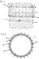
- anode structure 1 according to an illustrative embodiment of the invention will now be described in reference to Figures 1 to 5 .
- the anode structure 1 is provided as an anode cage.
- the anode cage 1 comprises a frame formed of an upper ring 3, a lower ring 6, and a plurality of anode pipes 4 connecting between the two rings.
- the frame may be made of engineering steel and is configured to receive the monopile body 2 through its bore, as shown in Figure 1 , and from above in Figure 2 .
- the lower ring 6 also has a slightly larger diameter than the upper ring 3 so that the anode cage 1 fits over and mates to the conical section of the body 2.
- the connection points for the anode cage 1 may be welded or otherwise installed onto the monopile.
- each anode pipe 4 comprises a jacket of anode material 5 surrounding the section of anode pipe 4 between the upper and lower rings 3 and 6.
- each jacket of anode material 5 forms an anode element between the two rings 3 and 6.
- the anode material 5 is formed of a material having a lower electrode potential than the body of the monopile 2.
- suitable anode materials are less noble metals, such as zinc or magnesium, or alloys thereof.
- the anode material 5 is electrically connected to the anode pipe 4 and, in turn, the upper and lower rings 3 and 6.
- Figure 1 shows a side view of a section of the monopile body 2.
- the bulk of the body's surface is covered in an anti-corrosion paint 7.
- the body 2 further comprises an unpainted horizontal strip 8 around its circumference.
- the width of the strip 8 is relatively large to allow for tolerances in the position of where the anode cage sits when fitted, and in preferred embodiments may be 1-2 meters wide.
- the surface of the monopile body 2 is substantially defined by a larger coated region 7 and a smaller uncoated region 8 which exposes the underlying substrate material of the body 2.
- the monopile body 2 is further provided with an auxiliary access strip 11 located below the unpainted horizontal strip 8 for allowing a cable to be separately retrofitted between the monopile body 2 and the anode cage 1 if the primary electrical connection described below is disrupted.
- the lower ring 6 is provided with a plurality of connection elements 10 which can be securely fastened to the monopile body 2 once the anode cage 1 has been correctly positioned.
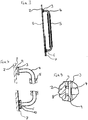
- Figure 3 shows a vertical cross-sectional view through one of the anode elements 5 when contacting the monopile body 2.
- Figure 4 shows enlarged views of each end of the anode element shown in Figure 3 .
- the middle of the anode pipe 4 is surrounded by anode material 5, and its ends terminate in the upper and lower rings 3 and 6.
- connection element 10 which, once the anode cage is installed, rests on the monopile body 2 and stabilises the cage structure 1.
- the connection elements 10 may be fastened to the monopile body 2 to secure the anode cage in position.
- the end terminating with the upper ring 3 is provided with a contact formation 9 which, once the anode cage is installed, aligns with the uncoated region 8 on the monopile body 2.
- Figure 5 shows an enlarged horizontal cross sectional view of the contact formation 9.
- the contact formation 9 comprises two inwardly projecting projections which engage with the surface of the uncoated region 8 to provide an electrical connection thereto.
- the two projections of the contact formation 10 project inward by different distances. That is, one of the projections is a primary projection that extends further inward than the other, secondary projection.
- the primary projection forms the primary electrical connection with the body 2, with the secondary projection providing a backup contact in the event that the primary projection fails or is otherwise damaged.
- connection element 10 and contact formation 9 are associated with both a connection element 10 and contact formation 9, it will be understood that not every anode pipe 4 needs to have these. That is, a smaller number of connection elements 10 and contact formations 9 may be distributed around the anode cage to provide a simplified arrangement. As such, some anode pipes 4 may simply provide the framework between the upper and lower rings 3 and 6.
- the anode cage 1 may be lowered over the monopile body 2 until the contact formations 9 align and engage with the uncoated region 8.
- the connection elements 10 may also rest on the surface of the body 2 at a fixing location.
- the connection elements 10 may then be fastened at the fixing location for securing the anode cage 1.
- the anode elements 5 are thereby electrically connected to the monopile 2 and, owning to their lower electrode potential, act to provide galvanic corrosion resistance. In this way, when exposed to water, the anode material 5 will be sacrificially corroded, rather than the monopile 2.
- the present invention allows the anode structure 1 to be electrically connected directly to the foundation body 2, without requiring separate connection cables. This thereby allows for more straightforward installation and a more reliable earthing connection between the structures.
- the present invention also avoids or minimises the need to employ divers or ROVs devices to install the anode structure.
- the anode structure and the foundation itself may be constructed from a variety of materials. It will also be understood that the various foundation types and configurations may be used. It is also preferable that the anode structure comprises at least 3 contact elements 10 and connection formations 9 for assuring mechanical and electrical connections to the foundation body.
- anode structure may further comprise sensors as auxiliary means for monitoring the status of the foundation.
- the anode cage is generally made of steel or similar metal (black steel, galvanized steel, etc.), the anodes are fixed on dedicated inserts which are generally welded and/or bolted on the upper and lower ring.
- the supports connecting the anode cage to the foundation via direct contact are welded or bolted to the upper ring (or alternatively to the lower ring or both to upper and to lower ring).
- the weight of the anode cage itself causes the frame and/or the supports to deform to enhance the contact area between supports and the foundation body.
- the supports can be made of any conductive material, such as steel or copper.
- the anode cage is positioned by means of a suitable crane, and simply lowered onto the foundation body until it finally sits in the planned position.
- no specific orientation is required as the anode cage can be freely oriented since it is not necessary to align any cables or connection terminals to establish the electric connectivity between the anode cage and the foundation.
Landscapes
- Engineering & Computer Science (AREA)
- General Engineering & Computer Science (AREA)
- Mechanical Engineering (AREA)
- Civil Engineering (AREA)
- Structural Engineering (AREA)
- Prevention Of Electric Corrosion (AREA)
Priority Applications (1)
| Application Number | Priority Date | Filing Date | Title |
|---|---|---|---|
| EP19205690.1A EP3594411A3 (fr) | 2019-10-28 | 2019-10-28 | Structure d'anode pour fondation offshore, et procédé de réduction de la corrosion dans une fondation offshore |
Applications Claiming Priority (1)
| Application Number | Priority Date | Filing Date | Title |
|---|---|---|---|
| EP19205690.1A EP3594411A3 (fr) | 2019-10-28 | 2019-10-28 | Structure d'anode pour fondation offshore, et procédé de réduction de la corrosion dans une fondation offshore |
Publications (2)
| Publication Number | Publication Date |
|---|---|
| EP3594411A2 true EP3594411A2 (fr) | 2020-01-15 |
| EP3594411A3 EP3594411A3 (fr) | 2020-01-22 |
Family
ID=68382341
Family Applications (1)
| Application Number | Title | Priority Date | Filing Date |
|---|---|---|---|
| EP19205690.1A Withdrawn EP3594411A3 (fr) | 2019-10-28 | 2019-10-28 | Structure d'anode pour fondation offshore, et procédé de réduction de la corrosion dans une fondation offshore |
Country Status (1)
| Country | Link |
|---|---|
| EP (1) | EP3594411A3 (fr) |
Cited By (2)
| Publication number | Priority date | Publication date | Assignee | Title |
|---|---|---|---|---|
| CN113062365A (zh) * | 2021-02-09 | 2021-07-02 | 中国能源建设集团广东省电力设计研究院有限公司 | 套笼装置 |
| EP4184005A1 (fr) * | 2021-11-23 | 2023-05-24 | Siemens Gamesa Renewable Energy A/S | Cage de monopieu d'une éolienne offshore, tour d'une éolienne offshore, éolienne offshore et procédé d'installation d'une tour d'une éolienne offshore |
Citations (1)
| Publication number | Priority date | Publication date | Assignee | Title |
|---|---|---|---|---|
| EP3483342A1 (fr) | 2017-11-10 | 2019-05-15 | GeoSea NV | Dispositif et procédé d'agencement d'une construction secondaire sur une construction primaire offshore |
Family Cites Families (3)
| Publication number | Priority date | Publication date | Assignee | Title |
|---|---|---|---|---|
| US3719049A (en) * | 1969-12-22 | 1973-03-06 | Durant D | Corrosion preventing apparatus and method |
| US4659255A (en) * | 1984-07-19 | 1987-04-21 | Nippon Steel Corporation | Marine structure of precoated corrosion resistant steel pipe piles |
| US4609307A (en) * | 1984-11-05 | 1986-09-02 | Exxon Production Research Co. | Anode pod system for offshore structures and method of installation |
-
2019
- 2019-10-28 EP EP19205690.1A patent/EP3594411A3/fr not_active Withdrawn
Patent Citations (1)
| Publication number | Priority date | Publication date | Assignee | Title |
|---|---|---|---|---|
| EP3483342A1 (fr) | 2017-11-10 | 2019-05-15 | GeoSea NV | Dispositif et procédé d'agencement d'une construction secondaire sur une construction primaire offshore |
Cited By (3)
| Publication number | Priority date | Publication date | Assignee | Title |
|---|---|---|---|---|
| CN113062365A (zh) * | 2021-02-09 | 2021-07-02 | 中国能源建设集团广东省电力设计研究院有限公司 | 套笼装置 |
| EP4184005A1 (fr) * | 2021-11-23 | 2023-05-24 | Siemens Gamesa Renewable Energy A/S | Cage de monopieu d'une éolienne offshore, tour d'une éolienne offshore, éolienne offshore et procédé d'installation d'une tour d'une éolienne offshore |
| US12247368B2 (en) | 2021-11-23 | 2025-03-11 | Siemens Gamesa Renewable Energy A/S | Cage for a monopile of an offshore wind turbine, tower for an offshore wind turbine, offshore wind turbine and method for installing a tower of an offshore wind turbine |
Also Published As
| Publication number | Publication date |
|---|---|
| EP3594411A3 (fr) | 2020-01-22 |
Similar Documents
| Publication | Publication Date | Title |
|---|---|---|
| EP2185816B2 (fr) | Fondation monopieu pour une éolienne située en mer | |
| EP3255210B1 (fr) | Procédé d'installation d'une structure en mer | |
| KR20220058921A (ko) | 해상 전력 분배 | |
| US20150292175A1 (en) | Working Platform For An Offshore Wind Energy Plant And Method For Manufacturing The Same | |
| CA2778376A1 (fr) | Support pour anodes destine a des dispositifs de protection anticorrosion cathodique de tubes de fondation d'eoliennes en mer, tube de fondation d'une eolienne en mer et structurede liaison placee entre un support pour anodes et un tube de fondation, dispositif de protection anticorrosion cathodique pour tubes de fondation d'eoliennes en mer et eolienne en | |
| US20080199258A1 (en) | Retrievable surface installed cathodic protection for marine structures | |
| CA1313510C (fr) | Systeme de protection cathodique par courant impose pour plates-formes marines, a cables anodiques tendus | |
| GB2473058A (en) | Transition piece with conduit located around the pile of an offshore installation | |
| TWI773758B (zh) | 離岸設施 | |
| CN113062365A (zh) | 套笼装置 | |
| US10738431B2 (en) | Connection structure for a marine installation, marine installation and method of erecting a marine installation | |
| CN113981454B (zh) | 浮式平台的外加电流阴极保护局部修复装置及其修复方法 | |
| CN104278277A (zh) | 阴极保护快速修复用牺牲阳极堆 | |
| WO2023088786A1 (fr) | Procédé pour l'agencement d'au moins un composant pendant l'installation d'une éolienne | |
| CN207738843U (zh) | 一种海洋平台张紧式外加电流阴极保护系统 | |
| US4609307A (en) | Anode pod system for offshore structures and method of installation | |
| CN116315944A (zh) | 基于水下插拔电连接器阴极保护快速修复装置及修复方法 | |
| CN103835304B (zh) | 一种高桩承台基础结构 | |
| EP4385877A1 (fr) | Ensemble de connexion flottant temporaire | |
| US12624458B2 (en) | Gravity-contact sacrificial anode | |
| CN114016040A (zh) | 吸力筒导管架基础外加电流阴极保护系统 | |
| CN220393913U (zh) | 一种海上风力发电机组外加电流专用阳极装置 | |
| CN112048723A (zh) | 一种用于深海的阴极保护装置 | |
| CN222274703U (zh) | 桩桶复合基础外加电流阴极保护系统 | |
| CN203716170U (zh) | 一种高桩承台基础结构 |
Legal Events
| Date | Code | Title | Description |
|---|---|---|---|
| PUAI | Public reference made under article 153(3) epc to a published international application that has entered the european phase |
Free format text: ORIGINAL CODE: 0009012 |
|
| STAA | Information on the status of an ep patent application or granted ep patent |
Free format text: STATUS: THE APPLICATION HAS BEEN PUBLISHED |
|
| PUAL | Search report despatched |
Free format text: ORIGINAL CODE: 0009013 |
|
| AK | Designated contracting states |
Kind code of ref document: A2 Designated state(s): AL AT BE BG CH CY CZ DE DK EE ES FI FR GB GR HR HU IE IS IT LI LT LU LV MC MK MT NL NO PL PT RO RS SE SI SK SM TR |
|
| AX | Request for extension of the european patent |
Extension state: BA ME |
|
| AK | Designated contracting states |
Kind code of ref document: A3 Designated state(s): AL AT BE BG CH CY CZ DE DK EE ES FI FR GB GR HR HU IE IS IT LI LT LU LV MC MK MT NL NO PL PT RO RS SE SI SK SM TR |
|
| AX | Request for extension of the european patent |
Extension state: BA ME |
|
| RIC1 | Information provided on ipc code assigned before grant |
Ipc: E02B 17/00 20060101AFI20191219BHEP |
|
| STAA | Information on the status of an ep patent application or granted ep patent |
Free format text: STATUS: THE APPLICATION IS DEEMED TO BE WITHDRAWN |
|
| 18D | Application deemed to be withdrawn |
Effective date: 20200723 |