EP3594571A1 - Brenner für handwerkzeug mit gasverbrennung, und mit einem solchen brenner ausgestattetes handwerkzeug - Google Patents
Brenner für handwerkzeug mit gasverbrennung, und mit einem solchen brenner ausgestattetes handwerkzeug Download PDFInfo
- Publication number
- EP3594571A1 EP3594571A1 EP19185680.6A EP19185680A EP3594571A1 EP 3594571 A1 EP3594571 A1 EP 3594571A1 EP 19185680 A EP19185680 A EP 19185680A EP 3594571 A1 EP3594571 A1 EP 3594571A1
- Authority
- EP
- European Patent Office
- Prior art keywords
- lance
- burner
- injector
- intermediate tube
- tube
- Prior art date
- Legal status (The legal status is an assumption and is not a legal conclusion. Google has not performed a legal analysis and makes no representation as to the accuracy of the status listed.)
- Pending
Links
Images


Classifications
-
- F—MECHANICAL ENGINEERING; LIGHTING; HEATING; WEAPONS; BLASTING
- F23—COMBUSTION APPARATUS; COMBUSTION PROCESSES
- F23D—BURNERS
- F23D14/00—Burners for combustion of a gas, e.g. of a gas stored under pressure as a liquid
- F23D14/02—Premix gas burners, i.e. in which gaseous fuel is mixed with combustion air upstream of the combustion zone
- F23D14/04—Premix gas burners, i.e. in which gaseous fuel is mixed with combustion air upstream of the combustion zone induction type, e.g. Bunsen burner
- F23D14/08—Premix gas burners, i.e. in which gaseous fuel is mixed with combustion air upstream of the combustion zone induction type, e.g. Bunsen burner with axial outlets at the burner head
-
- F—MECHANICAL ENGINEERING; LIGHTING; HEATING; WEAPONS; BLASTING
- F23—COMBUSTION APPARATUS; COMBUSTION PROCESSES
- F23D—BURNERS
- F23D14/00—Burners for combustion of a gas, e.g. of a gas stored under pressure as a liquid
- F23D14/38—Torches, e.g. for brazing or heating
-
- F—MECHANICAL ENGINEERING; LIGHTING; HEATING; WEAPONS; BLASTING
- F23—COMBUSTION APPARATUS; COMBUSTION PROCESSES
- F23D—BURNERS
- F23D14/00—Burners for combustion of a gas, e.g. of a gas stored under pressure as a liquid
- F23D14/46—Details
- F23D14/48—Nozzles
- F23D14/52—Nozzles for torches; for blow-pipes
Definitions
- the invention relates to a burner for a gas-fired hand tool, of the type comprising a tubular lance, associated on one side with a high pressure injector and, on the other, with a flame attachment zone. , the lance having at least a first intake of ambient air.
- the lance constitutes the body of the burner. It has at least a first intake of ambient air, so that gas leaving the injector mixes with this air inside the lance, along the latter, before reaching the zone of flame catch, where the mixture ignites.
- a lance is characterized by its elongated shape, relatively long in comparison with its diameter. Generally, the length to diameter ratio of a lance is greater than 4. Burners with lance are distinguished from short burners, in particular torch type burners, the ratio in question is generally close to 2 or 3. Burners with lance produces a flame in the general form of a dart, accompanied by an essentially surface combustion. Flames of this type are generally more efficient than those produced by short burners, which are generally apple-shaped and are accompanied by essentially mass or volume combustion.
- the high pressure injector is connected to a gas source via a flow variator, typically integrated into the tool, which is controlled using a trigger or a tap, for example.
- This variator makes it possible to vary the flow rate to a large extent, in particular in a ratio of 1 to 2.5 or 3. This ratio typically corresponds to a flow rate varying between 1 and 4 bars approximately.
- burners of the type described above which is designated "with a premix flame" it may happen that flames penetrate inside the lance from the flame attachment zone. This is particularly the case when the injection pressure weakens, for example due to a lower gas flow rate following a shutdown of the fuel gas supply.
- the flashbacks are favored when the lance has a large cross section in comparison with its length, that is to say when the ratio of the length of the lance to the diameter thereof. This is weak.
- an injector of a certain power corresponding to the nominal power of the tool, on the lance of a tool of higher nominal power, longer, one practically eliminates any risk of flashback.
- a difficulty is that, for reasons of ergonomics, tools of lower power are used precisely for their shorter lance.
- the Applicant has set itself the objective of improving this situation.
- this involves providing a burner in which the lance can be shortened, without impact on the risk of flashback, or the shape of this flame.
- a burner for a gas combustion hand tool of the type comprising a tubular lance, associated on one side with a high pressure gas injector and, on the other with a combustion zone.
- the lance has at least a first intake of ambient air.
- This burner further comprises an intermediate tube, partially housed at least inside the lance, between the injector and the combustion zone.
- This intermediate tube has a second intake of ambient air. This second intake is located near the first and the injector.
- the intermediate tube has a smaller diameter than the lance.
- the second air intake is closer to the injector than to an end of the intermediate tube opposite the injector.
- the gas first borrows the intermediate tube where it mixes with air which it sucks in through the second intake. It is a first path of mixing.
- the first air intake is closer to the second intake than to the end of the intermediate tube opposite the injector.
- the gas / air mixture borrows the lance where it mixes with air which it sucks in through the first intake. It is a second mixing path.
- the gas When the gas pressure is low at the injector, the gas has a low air suction capacity, which results from a low speed of this gas leaving the injector. However, the need for air is reduced because the amount of gas injected is also reduced.
- the air is mainly sucked into the intermediate tube, through the second air intake.
- the central section of the intermediate tube is preponderant: the gas is mainly diluted in this tube.
- the burner works as if its dilution neck consisted of the intermediate tube only. The dilution rate is good.
- the speed of the mixture is high enough to limit the risk of a flashback.
- the gas When the gas pressure is high at the injector, the gas has a high air suction capacity, which results from a high speed of this gas at the outlet of the injector.
- the need for air is increased because the quantity of gas injected is also increased.
- a first part of the air of the mixture is sucked through the second inlet, into the intermediate tube, while a second part of this air is sucked through the first inlet, into the space between the outside of the intermediate tube and the interior of the lance.
- the gas is first diluted in the intermediate tube and then in the lance. The dilution rate remains good. The risk of flashback is not increased.
- the first path and the second path are not mutually exclusive. In practice, the air / gas mixture is done on these two paths. It is their relative influence which varies: at low pressure, the first path is preponderant, the mixing is mainly done along the intermediate tube while at high pressure, it is the second path which predominates, the mixing is mainly along the lance, downstream of the intermediate tube to the flame attachment zone.
- a gas combustion hand tool comprising a burner of the type proposed above.
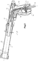
- a gas combustion hand tool 1 comprises an elongated body 3 and a gripping member in the form of a handle 5 integral with the body 3.
- the tool 1 further comprises a burner 7 mounted at a longitudinal end of the body 3 , here in a removable manner.
- the body 3 is connected to the handle 5 at one end of this handle 5.
- the handle 5 carries a gas connection 9 able to be connected to a source of pressurized combustible gas, in particular by through a flexible hose.
- the handle 5 also houses a gas pressure regulator 11, an inlet of which is fluidly connected to an outlet of the gas connection 9, an all-or-nothing valve 13, of which an inlet is fluidly connected to the outlet of the regulator 11, and a second T-connector 15, one inlet of which is fluidly connected to the outlet of the valve 13.
- the body 3 also houses an injector 17, an inlet of which is fluidly connected to an outlet of the second fitting 15.
- the injector 13 is of the high pressure type, that is to say that in practice the injector 17 is capable of operating at injection pressures between 0.9 bar and 4 bar.
- the injector 17 is in the form of an elongated nozzle, the outlet of which constitutes the outlet of the injector 17.
- the value 0.9 bar corresponds by definition to the high pressure threshold, when the gas enters a sonic regime at the injector 17. In this case, there is no defined ceiling value for high pressure. However, for liquefied petroleum gas, the maximum injection pressure should not exceed the pressure at the critical point. In practice, propane is generally used in a relaxed form, which corresponds to a ceiling value of 4 bars.
- the valve 13 is actuated by a lever 18 moved by the upper part of a trigger 19 mounted in translation on the handle 5.
- the gas flow at the inlet of the valve 13 is regulated by the regulator 11, which is actuated by a part lower of the trigger 19. This lower part is able to pivot slightly with respect to the upper part of the trigger 19.
- the valve 13 prohibits any supply of combustible gas to the second connector 15 and to the injector 17. If the lower part of this trigger 19 is not pressed, the regulator 11 delivers at its output its smallest operating pressure. This pressure corresponds to an ignition pressure. Pressing the lower part of the trigger 19 increases the pressure of the combustible gas at the outlet of the regulator 11, up to a maximum pressure, here close to 4 bars.
- the burner 7 comprises an elongated body, or lance 21, generally tubular.
- the burner 7 further comprises a device 23, arranged at one end of the lance 23.
- the lance 21 is associated with at least part of the injection assembly 13.
- the lance 21 is here produced in the form of a tube section of circular section, of diameter D2 and of length L2.
- the ratio of the length L2 of this portion to its diameter D2 is greater than 4, and more particularly greater than 5 and / or less than 8, depending in particular on the power of the injector 17.
- the device 23 here comprises an end piece 25 in the general form of a nozzle, mounted at one end of the lance 21 opposite to the injector 17.
- the end piece 25 has a general shape of revolution, here frustoconical.
- the end piece 25 includes a first large face by the intermediary of which the endpiece 25 is threaded onto the lance 21 and a second large face, axially opposite the first, on which the flame is intended to hang.
- the endpiece 25 comprises a bore which extends axially from the first to the second large face of the endpiece 25.
- This bore has a first segment 27 whose profile corresponds to the profile of the lance 21, at least over a zone of this lance 21 near its end.
- the first segment 27 is open on the first face of the nozzle 25.
- the first segment 27 receives an end portion of the lance 21.
- the bore of the endpiece 25 comprises a second segment 29, which extends axially from the first bore 27 to the second face of the endpiece 25.
- the second segment 29 is generally frustoconical.
- the device 23 further comprises a core part 31, generally frustoconical, held inside the second segment 29, coaxially with the latter, by means of a fin washer 33.
- the core 31 is traversed axially by a bore 35, here generally cylindrical.
- the bore 35 of the core 31 acts as a main conduit capable of fluidly connecting the interior of the lance 21 to the flame attachment surface.
- a secondary conduit 36 which extends axially and peripherally around the main conduit.
- the secondary conduit 36 is generally frustoconical and of annular cross section. The secondary conduit 36 opens onto the flame attachment zone in a generally transverse manner after having passed through the fins of the washer 33.
- the burner 7 comprises a sleeve-shaped part 37 by means of which the lance 21 is mounted on the body 3.
- the sleeve 37 has a general appearance of revolution, and two end faces mutually opposite along the axis of the sleeve 37.
- the sleeve 37 comprises a first bore 39 open on an end face of the sleeve 37 and which houses an end portion of the lance 21 opposite to the nozzle 25.
- the sleeve 37 also comprises a second bore 41, in the axis of the first, which opens onto an end face of the sleeve 37 remote from the lance 21.
- the second bore 41 houses a part at less than the injector 17.
- the injector 17 is held in the sleeve 37 so that it projects into the first bore 39.
- the sleeve 37 holds the injector 17 and the lance 23 coaxially.
- the injector 17 opens here at a distance from the proximal end of the lance 21.
- the first bore 39 of the sleeve 37 comprises a first end segment 43 in shape correspondence with an end portion of the lance 21, here cylindrical.
- This first bore 39 also comprises a second end segment 45, axially opposite the first end segment 43.
- the second segment 45 is here generally cylindrical, with a diameter less than the diameter of the first segment 43.
- the first bore 39 of the sleeve 37 also has an intermediate segment 47 which connects the first end segment 43 to the second end segment 45 by forming a shoulder surface 49 oriented towards the first end segment 43.
- the shoulder 49 forms an axial abutment against which the proximal end of the lance 21 rests.
- This lance 21 is fixed to the sleeve 37 by a screw 51 disposed across a wall of the sleeve 37 and of a wall of the lance. 21.
- the sleeve 37 is perforated.
- the sleeve 37 is pierced with louvers 53 which each place the inside of the first bore 39 in fluid communication with the outside of the sleeve 37.
- the louvers 53 are arranged opposite the first end segment 43 and the intermediate segment 47. Each opening 53 forms a primary air intake in the first bore 39, this primary air being taken from the ambient air.
- One end of the lance 21 opens into this first bore 39, near the intermediate segment 47.
- the lance 21 is in fluid communication with the first bore 39.
- the primary air admitted into the first bore 39 in particular at through gills 53, can penetrate inside the lance 21.
- the end in question of the lance 21 forms a primary air intake in the lance 21.
- the injector 17 opens here at the right of this admission of primary air in the first bore 39, that is to say vents 53 formed in the part 37.
- the injector 17 can be positioned axially in a different manner. In particular, the injector 17 can open axially beyond the end of the lance 21, or an air intake in this lance 21.
- the burner 7 comprises an additional tube 55 interposed between the outlet of the injector 17 and the outlet of the lance 21.
- the tube 55 is mounted in the sleeve 37, in the vicinity of the outlet of the injector 17 and coaxially with this last.
- the tube 55 is partially housed at least inside the lance 21, that is to say here in the bore of the tube portion forming this lance 21, coaxially.
- the tube 55 is housed in the end portion of the lance 21 which is received in the sleeve 37.
- the tube 55 protrudes from this end of the lance 21.
- the tube 55 opens firstly into the first bore 39 and, on the other hand, inside the lance 21, at a distance from the device 25. This distance is first of all useful for ignition: a short distance makes it more difficult to ignite the mixture with the device 25. A large distance also allows the mixture to adopt a laminar regime well before reaching the device 25 which also reduces the risk of flashback.
- the tube 55 has a length L1 much less than the length L2 of the lance 21.
- the ratio of the length L1 to the diameter D1 is preferably greater than 3, and more particularly greater than 3.5 or less than 5.
- the tube 55 abuts the intermediate segment 47, here in the immediate vicinity of the outlet of the injector 17.
- the tube 55 opens into the first bore 39 opposite the gills 53.
- the tube 55 is in fluid communication with the first bore 39.
- the primary air from this first bore 39 in particular admitted into through gills 53, can penetrate inside the tube 55 through this end.
- the end in question forms a primary air intake in the tube 55.
- the air intake in the tube 55 is closer to the outlet of the injector 17 than at one end of the tube 55 opposite the outlet of this nozzle 17.
- the air intake in the lance 21 is more as close to the air intake in the tube 55 as to the end of this tube 55 opposite the injector 17.
- the injector 17 opens at a distance A from the tube 55, in the axis and upstream of the latter.
- the distance A is small compared to the length of the tube 55.
- this distance A is less than 5 millimeters and / or greater than 3 millimeters.
- the tube 55 is held in position inside the lance 21 by a set of pins or feet 57, here six in number, arranged between the inside of the lance 21 and the intermediate tube 55.
- the feet 57 are distributed in two sets, arranged respectively on two zones axially distant from each other, ie distant from each other in a longitudinal direction of the intermediate tube 55.
- the feet 57 are fixed to the tube 55.
- the feet 57 s 'press against the wall of the lance 21.
- the feet 57 provide long guidance of the tube 55 inside the lance 21. A long guide prevents swiveling.
- the intermediate tube 55 is retained in the lance 21 at least in part by virtue of a threaded element disposed radially through the wall of the intermediate tube 55, here in the form of the screw 51 arranged across a wall of the sleeve 37 and d 'a wall of the lance 21.
- the burner 7 has two paths for the admission of ambient air and the mixing of this air with the combustion gas.
- combustion gas is ejected from the injector 17 into the tube 55.
- This ejection of pressurized gas causes a suction of primary air through the intake which is close to the injector 17, here l end of the tube 55.
- This primary air is sucked into the first bore 39 through the vents 53.
- the combustion gas and the primary air mix with each other inside the tube 55, as as the gas travels along it.
- the movement of the mixture causes a second suction of air, the admission of air, here through the end of the lance 21 close to the injector 17.
- This air is always sucked into the first bore 39 through the vents 53.
- This ambient air travels inside the lance 21, along it and outside the tube 55. It is the second path .
- the mixture of the first path combines with the air sucked in by the second path. This mixing continues as the mixture travels along the lance 21, until it reaches the device 25 where this mixture is ignited.
- Burner Injector power P (kW) Injector diameter (mm) A (mm) L1 (mm) L2 (mm) D1 (mm) D2 (mm) I 30 0.83 -0.5 60 130 12 23.6 II 70 1.2 3 50 150 14 23.6 III 90 1.6 3.4 80 180 17 33.1
- the following table 2 collects values calculated from the dimensional values of table 1. Burner L1 / P L2 / P D2 / D1 D1 / P D2 / P I 2.00 4.33 1.97 0.40 0.79 II 0.71 2.14 1.69 0.20 0.34 III 0.89 2.00 1.95 0.19 0.37
- the L1 / P and L2 / P ratios are quite similar for burners II and III. These ratios are higher for burner I.
- the length L2 of the burner I can be reduced compared to the value indicated in table 1, at least from a fluid point of view. Other considerations may lead to deviating from an optimal ratio, close to the ratio of burners II and III. For example, the length L2 can be kept greater than a minimum value to allow the mounting of a tar scraper, and the length L1 to allow a sufficient distance between the feet 57 to prevent the tube 55 from swiveling.
- the length L1 of the lance can be between 0.5 and 1.2 times the power P of the injector, expressed in kilowatt.
- the length L2 of the intermediate tube is between 1.5 and 2.5 times the power P of the injector expressed in kilowatt.
- the D1 / P and D2 / P ratios are quite similar for burners II and III. These ratios are higher for burner I.
- the diameters D1 and D2 of the burner I can be reduced, at least from a fluid point of view.
- the diameter D2 has not been modified in accordance with an optimized ratio, close to that of the burners II and III in order to allow the mounting of existing accessories.
- the diameter D1 has not been modified in order to keep the ratio D2 / D1 close to that of burner II.
- the ratio D2 / D1 is greater for burner I than for burner II, and lower for burner II than for burner III.
- a restriction ring can be added to the lance in order to artificially reduce the diameter of the lance 21 at the inlet (diameter D3).
- the diameter D3 is worth 25.40 millimeters, which corresponds to a ratio D3 / D1 close to 1.49.
- distance A is similar for burners II and III. This value is very different for burner I. This results from the fact that the dimensional values of burners I are effective but not necessarily optimized.
- the diameter D1 of the tube 55 can be determined, at least in part, as a function of the diameter D2 of the lance 21.
- the ratio between the diameter D2 and the diameter D1 can vary depending on the value of the length ratio L1 of the lance 21 on its diameter D1.
- the ratio of these diameters D2 and D1 can also vary depending on the pressure range expected. For example, the lower the minimum pressure, the smaller the diameter D1 of the tube 55 relative to the diameter D2 of the lance 21.
- the burner 37 has an electrode wire 59 for ignition.
- This wire 59 runs inside the lance 21, along the latter, from the end of the lance 23 near the injector 17 to near the device 25.
- This electrode wire is partly at least housed in the annular space which is between the inside of the lance 21 and the outside of the tube 55. In this intermediate space, there is almost exclusively fresh ambient air, without combustion gas. In the event of a flashback, the latter is fixed inside the tube 55. This tube protects the wire 59 from this flame.
- the graph shows the results of a test comparing two identical burners, one fitted with an intermediate tube of the type of tube 55 described above (burner A), the other without (burner B).
- the dimensions of burners A and B are the same, except for the length of the burner lance B which varies during the test.
- a pressure value corresponding to a flashback is measured, with a lance of length much less than the original length of the lance of burner B, here close to 180 millimeters (mark A in the shape of a square ).
- the A mark indicates a critical operating point for burner A: below this pressure value, there is a risk of flashback. However, this operating point is far from the curve C and from the marks B. Above all, this operating point is far below the curve C.
- the relative flame re-entry pressure decreases, here from 380 to 70 millibars. It's an 82 percent gain.
- the length of the lance can be reduced, here from 320 millimeters to 180 millimeters, a reduction of 44 percent.
- the proposed burner makes it possible to reduce the length of the lance with an equivalent risk, or to reduce this risk by keeping the same length of lance.
- the technician begins by determining the power of the injector required, essentially on the basis of the work to be carried out.
- the technician can deduce therefrom a conventional length of the dilution neck, that is to say the shortest length between (i) the air intake in the lance and the flame attachment zone and (ii) l injection of gas into the lance and the flame attachment zone.
- This classic length can be obtained from abacuses or by reproducing an existing burner. It can do the same for the diameter of this neck.
- the technician inserts a tube similar to the tube 55 described above. It can keep a lance length in accordance with the conventional length. Advantageously, however, it reduces the length of the lance compared to this conventional length, for example in a proportion greater than 40 percent, for example 44 percent. Other technical considerations, such as the management of manufacturing ranges, may lead to achieving this gain only partially.
- the intermediate tube can be integrated with burners having other geometries.
- the injector opens axially at the level of the air intake of the intermediate tube. This makes it possible to mix the primary air and the combustion gas over the entire path of the gas between the injection and the outlet of the intermediate tube. And as the air intake in the intermediate tube is done at the end of this tube, we optimize the size of this tube, in particular its length, according to a rate dilution sought. This further facilitates the design of the intermediate tube.
- the air introduced into the intermediate tube is already directed along the longitudinal axis of the intermediate tube, which is beneficial for the mixture. For the same reason, it is advantageous for the air to be admitted into the lance at one of the ends of the latter.
- the space is secondary, it is possible to unblock the injector inside the intermediate tube or upstream of it, and / or provide for air intakes in the intermediate tube and / or the lance. elsewhere than at their ends.
- the values of the lengths L1 and L2 indicated above are to be considered from their respective air intakes.
- An intermediate tube has been described which protrudes from the proximal end of the lance. It could be provided that the lance ends at the right of the intermediate tube, or beyond the proximal end of the latter.
- the sleeve 37 serves as a lance holder.
- the sleeve 37 is arranged on the one hand for mounting the lance 21 on the elongated body 3.
- the holding in position of the intermediate tube 55 relative to the injector 17 is essentially achieved by positioning this tube 55 relative to the lance 21.
- the sleeve 37 could be replaced, at least in part, by a longer lance, mounted for example directly on the elongated body 3.
- air intakes functionally analogous to the gills 53 are provided in the lance 21.
Landscapes
- Engineering & Computer Science (AREA)
- Chemical & Material Sciences (AREA)
- Combustion & Propulsion (AREA)
- Mechanical Engineering (AREA)
- General Engineering & Computer Science (AREA)
- Gas Burners (AREA)
Applications Claiming Priority (1)
| Application Number | Priority Date | Filing Date | Title |
|---|---|---|---|
| FR1856442A FR3083847B1 (fr) | 2018-07-12 | 2018-07-12 | Bruleur pour un outil a main a combustion de gaz et outil a main equipe d'un tel bruleur |
Publications (1)
| Publication Number | Publication Date |
|---|---|
| EP3594571A1 true EP3594571A1 (de) | 2020-01-15 |
Family
ID=65861324
Family Applications (1)
| Application Number | Title | Priority Date | Filing Date |
|---|---|---|---|
| EP19185680.6A Pending EP3594571A1 (de) | 2018-07-12 | 2019-07-11 | Brenner für handwerkzeug mit gasverbrennung, und mit einem solchen brenner ausgestattetes handwerkzeug |
Country Status (2)
| Country | Link |
|---|---|
| EP (1) | EP3594571A1 (de) |
| FR (1) | FR3083847B1 (de) |
Citations (4)
| Publication number | Priority date | Publication date | Assignee | Title |
|---|---|---|---|---|
| BE458552A (fr) * | 1941-07-19 | 1945-05-31 | Brûleur perfectionné, à gaz d'éclairage et autres gaz combustibles donnant avec l'air un mélange explosif | |
| FR2651559A1 (fr) * | 1989-09-01 | 1991-03-08 | Guilbert Express Sa | Chalumeau comprenant une poignee munie de deux organes de manóoeuvre. |
| EP0841518A2 (de) * | 1996-11-08 | 1998-05-13 | Shrinkfast Corporation | Heizpistole mit Hochleistungsstrahlpumpe und schnellwechselbaren Teilen |
| US20060018637A1 (en) * | 2004-07-26 | 2006-01-26 | Arlo Lin | Nozzle of gas hot air gun |
-
2018
- 2018-07-12 FR FR1856442A patent/FR3083847B1/fr active Active
-
2019
- 2019-07-11 EP EP19185680.6A patent/EP3594571A1/de active Pending
Patent Citations (4)
| Publication number | Priority date | Publication date | Assignee | Title |
|---|---|---|---|---|
| BE458552A (fr) * | 1941-07-19 | 1945-05-31 | Brûleur perfectionné, à gaz d'éclairage et autres gaz combustibles donnant avec l'air un mélange explosif | |
| FR2651559A1 (fr) * | 1989-09-01 | 1991-03-08 | Guilbert Express Sa | Chalumeau comprenant une poignee munie de deux organes de manóoeuvre. |
| EP0841518A2 (de) * | 1996-11-08 | 1998-05-13 | Shrinkfast Corporation | Heizpistole mit Hochleistungsstrahlpumpe und schnellwechselbaren Teilen |
| US20060018637A1 (en) * | 2004-07-26 | 2006-01-26 | Arlo Lin | Nozzle of gas hot air gun |
Also Published As
| Publication number | Publication date |
|---|---|
| FR3083847A1 (fr) | 2020-01-17 |
| FR3083847B1 (fr) | 2020-07-24 |
Similar Documents
| Publication | Publication Date | Title |
|---|---|---|
| CA2647145C (fr) | Dispositif de guidage d'un element dans un orifice d'une paroi de chambre de combustion de turbomachine | |
| CA2621843C (fr) | Controle d'alignement pour un systeme de decoupe par jet d'eau | |
| CA2679015C (fr) | Generateur d'air chaud | |
| EP2037174B1 (de) | Handwerkzeug mit verbesserter Gasverbrennung | |
| EP3594571A1 (de) | Brenner für handwerkzeug mit gasverbrennung, und mit einem solchen brenner ausgestattetes handwerkzeug | |
| FR3078142A1 (fr) | Chambre de combustion comportant deux types d'injecteurs dans lesquels les organes d'etancheite ont un seuil d'ouverture different | |
| FR2938444A1 (fr) | Dispositif de generation de mousse d'une lance a incendie | |
| FR2651559A1 (fr) | Chalumeau comprenant une poignee munie de deux organes de manóoeuvre. | |
| EP3977013B1 (de) | Verbrennungsanordnung mit einem vorverdampfungsrohr | |
| FR2884894A1 (fr) | Cartouche de gaz de combustion pour appareil de fixation a gaz | |
| EP2568217B1 (de) | Strahlrohr für Handwerkzeug, das sich ohne Temperaturdispersion entlang des Rohrs aufheizt | |
| EP3477197B1 (de) | Heizwerkzeug mit gasverbrennung, insbesondere vom typ lötkolben oder eisen zum kantenabstossen | |
| CA2152397A1 (fr) | Buse de chalumeau a gaz | |
| FR2864206A3 (fr) | Bruleur pour un gril de barbecue a gaz | |
| EP0882522A1 (de) | Lanze und Vorrichtung zur Erzeugung eines Strahles aus flüssigem CO2 und dessen Anwendung in einer Oberflächenreinigungseinrichtung | |
| FR2536679A1 (fr) | Lance perfectionnee de projection d'un produit fluide ou solide et en particulier lance a incendie | |
| EP4249084A1 (de) | Lanze für feuerlöscher und feuerlöscher mit einer solchen lanze | |
| FR2859120A1 (fr) | Fer a souder a caracteristiques d'echauffement ameliorees | |
| FR2713311A1 (fr) | Brûleur à gaz et dispositif d'optimisation de l'allumage de ce brûleur. | |
| FR2989451A1 (fr) | Deflecteur a tenue thermique amelioree pour systeme d'injection de chambre de combustion de turbomachine | |
| FR2847184A1 (fr) | Fer a souder a allumage a pierre | |
| FR2977125A1 (fr) | Desherbeur thermique a gaz sans flamme visible | |
| WO2003098109A1 (fr) | Chalumeau et dispositif permettant de former un chalumeau | |
| BE373650A (de) | ||
| FR2743407A1 (fr) | Veilleuse de controle d'atmosphere pour appareil a gaz |
Legal Events
| Date | Code | Title | Description |
|---|---|---|---|
| PUAI | Public reference made under article 153(3) epc to a published international application that has entered the european phase |
Free format text: ORIGINAL CODE: 0009012 |
|
| STAA | Information on the status of an ep patent application or granted ep patent |
Free format text: STATUS: THE APPLICATION HAS BEEN PUBLISHED |
|
| AK | Designated contracting states |
Kind code of ref document: A1 Designated state(s): AL AT BE BG CH CY CZ DE DK EE ES FI FR GB GR HR HU IE IS IT LI LT LU LV MC MK MT NL NO PL PT RO RS SE SI SK SM TR |
|
| AX | Request for extension of the european patent |
Extension state: BA ME |
|
| STAA | Information on the status of an ep patent application or granted ep patent |
Free format text: STATUS: REQUEST FOR EXAMINATION WAS MADE |
|
| 17P | Request for examination filed |
Effective date: 20200618 |
|
| STAA | Information on the status of an ep patent application or granted ep patent |
Free format text: STATUS: EXAMINATION IS IN PROGRESS |
|
| 17Q | First examination report despatched |
Effective date: 20220211 |