EP3594699A2 - Differentialschutzvorrichtung - Google Patents
Differentialschutzvorrichtung Download PDFInfo
- Publication number
- EP3594699A2 EP3594699A2 EP19177898.4A EP19177898A EP3594699A2 EP 3594699 A2 EP3594699 A2 EP 3594699A2 EP 19177898 A EP19177898 A EP 19177898A EP 3594699 A2 EP3594699 A2 EP 3594699A2
- Authority
- EP
- European Patent Office
- Prior art keywords
- detection
- fault
- secondary winding
- control module
- processing unit
- Prior art date
- Legal status (The legal status is an assumption and is not a legal conclusion. Google has not performed a legal analysis and makes no representation as to the accuracy of the status listed.)
- Granted
Links
Images

Classifications
-
- H—ELECTRICITY
- H02—GENERATION; CONVERSION OR DISTRIBUTION OF ELECTRIC POWER
- H02H—EMERGENCY PROTECTIVE CIRCUIT ARRANGEMENTS
- H02H3/00—Emergency protective circuit arrangements for automatic disconnection directly responsive to an undesired change from normal electric working condition with or without subsequent reconnection ; integrated protection
- H02H3/26—Emergency protective circuit arrangements for automatic disconnection directly responsive to an undesired change from normal electric working condition with or without subsequent reconnection ; integrated protection responsive to difference between voltages or between currents; responsive to phase angle between voltages or between currents
- H02H3/32—Emergency protective circuit arrangements for automatic disconnection directly responsive to an undesired change from normal electric working condition with or without subsequent reconnection ; integrated protection responsive to difference between voltages or between currents; responsive to phase angle between voltages or between currents involving comparison of the voltage or current values at corresponding points in different conductors of a single system, e.g. of currents in go and return conductors
- H02H3/33—Emergency protective circuit arrangements for automatic disconnection directly responsive to an undesired change from normal electric working condition with or without subsequent reconnection ; integrated protection responsive to difference between voltages or between currents; responsive to phase angle between voltages or between currents involving comparison of the voltage or current values at corresponding points in different conductors of a single system, e.g. of currents in go and return conductors using summation current transformers
- H02H3/332—Emergency protective circuit arrangements for automatic disconnection directly responsive to an undesired change from normal electric working condition with or without subsequent reconnection ; integrated protection responsive to difference between voltages or between currents; responsive to phase angle between voltages or between currents involving comparison of the voltage or current values at corresponding points in different conductors of a single system, e.g. of currents in go and return conductors using summation current transformers with means responsive to DC component in the fault current
-
- G—PHYSICS
- G01—MEASURING; TESTING
- G01R—MEASURING ELECTRIC VARIABLES; MEASURING MAGNETIC VARIABLES
- G01R19/00—Arrangements for measuring currents or voltages or for indicating presence or sign thereof
- G01R19/0007—Frequency selective voltage or current level measuring
-
- G—PHYSICS
- G01—MEASURING; TESTING
- G01R—MEASURING ELECTRIC VARIABLES; MEASURING MAGNETIC VARIABLES
- G01R19/00—Arrangements for measuring currents or voltages or for indicating presence or sign thereof
- G01R19/10—Measuring sum, difference or ratio
-
- H—ELECTRICITY
- H02—GENERATION; CONVERSION OR DISTRIBUTION OF ELECTRIC POWER
- H02H—EMERGENCY PROTECTIVE CIRCUIT ARRANGEMENTS
- H02H1/00—Details of emergency protective circuit arrangements
- H02H1/06—Arrangements for supplying operative power
- H02H1/063—Arrangements for supplying operative power primary power being supplied by fault current
-
- H—ELECTRICITY
- H02—GENERATION; CONVERSION OR DISTRIBUTION OF ELECTRIC POWER
- H02H—EMERGENCY PROTECTIVE CIRCUIT ARRANGEMENTS
- H02H1/00—Details of emergency protective circuit arrangements
- H02H1/06—Arrangements for supplying operative power
- H02H1/063—Arrangements for supplying operative power primary power being supplied by fault current
- H02H1/066—Arrangements for supplying operative power primary power being supplied by fault current and comprising a shunt regulator
-
- H—ELECTRICITY
- H02—GENERATION; CONVERSION OR DISTRIBUTION OF ELECTRIC POWER
- H02H—EMERGENCY PROTECTIVE CIRCUIT ARRANGEMENTS
- H02H3/00—Emergency protective circuit arrangements for automatic disconnection directly responsive to an undesired change from normal electric working condition with or without subsequent reconnection ; integrated protection
- H02H3/26—Emergency protective circuit arrangements for automatic disconnection directly responsive to an undesired change from normal electric working condition with or without subsequent reconnection ; integrated protection responsive to difference between voltages or between currents; responsive to phase angle between voltages or between currents
- H02H3/32—Emergency protective circuit arrangements for automatic disconnection directly responsive to an undesired change from normal electric working condition with or without subsequent reconnection ; integrated protection responsive to difference between voltages or between currents; responsive to phase angle between voltages or between currents involving comparison of the voltage or current values at corresponding points in different conductors of a single system, e.g. of currents in go and return conductors
- H02H3/33—Emergency protective circuit arrangements for automatic disconnection directly responsive to an undesired change from normal electric working condition with or without subsequent reconnection ; integrated protection responsive to difference between voltages or between currents; responsive to phase angle between voltages or between currents involving comparison of the voltage or current values at corresponding points in different conductors of a single system, e.g. of currents in go and return conductors using summation current transformers
-
- H—ELECTRICITY
- H02—GENERATION; CONVERSION OR DISTRIBUTION OF ELECTRIC POWER
- H02H—EMERGENCY PROTECTIVE CIRCUIT ARRANGEMENTS
- H02H3/00—Emergency protective circuit arrangements for automatic disconnection directly responsive to an undesired change from normal electric working condition with or without subsequent reconnection ; integrated protection
- H02H3/26—Emergency protective circuit arrangements for automatic disconnection directly responsive to an undesired change from normal electric working condition with or without subsequent reconnection ; integrated protection responsive to difference between voltages or between currents; responsive to phase angle between voltages or between currents
- H02H3/32—Emergency protective circuit arrangements for automatic disconnection directly responsive to an undesired change from normal electric working condition with or without subsequent reconnection ; integrated protection responsive to difference between voltages or between currents; responsive to phase angle between voltages or between currents involving comparison of the voltage or current values at corresponding points in different conductors of a single system, e.g. of currents in go and return conductors
- H02H3/34—Emergency protective circuit arrangements for automatic disconnection directly responsive to an undesired change from normal electric working condition with or without subsequent reconnection ; integrated protection responsive to difference between voltages or between currents; responsive to phase angle between voltages or between currents involving comparison of the voltage or current values at corresponding points in different conductors of a single system, e.g. of currents in go and return conductors of a three-phase system
- H02H3/347—Emergency protective circuit arrangements for automatic disconnection directly responsive to an undesired change from normal electric working condition with or without subsequent reconnection ; integrated protection responsive to difference between voltages or between currents; responsive to phase angle between voltages or between currents involving comparison of the voltage or current values at corresponding points in different conductors of a single system, e.g. of currents in go and return conductors of a three-phase system using summation current transformers
-
- H—ELECTRICITY
- H02—GENERATION; CONVERSION OR DISTRIBUTION OF ELECTRIC POWER
- H02H—EMERGENCY PROTECTIVE CIRCUIT ARRANGEMENTS
- H02H9/00—Emergency protective circuit arrangements for limiting excess current or voltage without disconnection
- H02H9/04—Emergency protective circuit arrangements for limiting excess current or voltage without disconnection responsive to excess voltage
- H02H9/041—Emergency protective circuit arrangements for limiting excess current or voltage without disconnection responsive to excess voltage using a short-circuiting device
Definitions
- the present invention relates to the field of differential protection devices, preferably of type B and / or B +, as well as electrical protection devices comprising such a differential protection device.
- a differential protection device of type B and / or B + in particular allows the detection of fault currents with DC and AC components. More particularly, a type B differential protection device makes it possible to detect fault currents for frequencies ranging from 0 to 1 kiloHertz, while a type B + differential protection device makes it possible to detect fault currents ranging from 0 to 20 kiloHertz.
- a differential protection device of type B and / or B + usually comprises a module for measuring a fault current configured to supply a fault signal proportional to the fault current comprising at least one toroid crossed by at least two conductors, of an electrical installation, forming a primary winding and comprising a secondary winding capable of supplying the fault signal representing the fault current.
- the device further comprises a detection and control module configured to process the fault signal and to control an actuator that the device comprises if the fault signal crosses a predetermined tripping threshold.
- a selective type B and / or B + differential protection device the tripping threshold of which is, for example, 300 milliamps, in order to protect the fire-fighting premises.
- the standards currently in force, and in particular the IEC 62423 and IEC 61008 standards require that the tripping times of a selective type B and / or B + differential protection device, having a tripping threshold of Idn, be between 150 milliseconds and 500 milliseconds for a frequency equal to 50 Hertz at Idn and for a frequency of 1 kilohertz at 14 Idn, the trigger time must be between 130 milliseconds and 500 milliseconds.
- the aforementioned standards impose a test at 5 Amps and at 50 Hertz, for which the trigger times must be between 40 milliseconds and 150 milliseconds and another test at 4.2 Amps and 1000 Hertz, for which the trigger times must be between 130 milliseconds and 500 milliseconds.
- protective devices of type B and / or B + selective, functional and in accordance with the abovementioned standards have the drawback of at least partially depending on the supply of the network to guarantee their operation at high frequency, c '' i.e. for frequencies between a few tens of Hertz to a few tens of kiloHertz.
- the object of the present invention is to overcome these drawbacks by proposing a solution in accordance with the above-mentioned standards and which does not need to be supplied by the network.
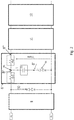
- the measurement module 3 and the detection and control module 6 form an AC / A / HI / G / F module.
- the detection and control module 6 only requires the electrical energy supplied by the fault current. No electrical supply, nor any electrical connection to the network is necessary to guarantee the proper functioning of this detection and control module 6.
- the processing unit 8 which, for an identical fault current , makes it possible to process both a fault signal at the frequency of 50 Hertz and a fault signal at the frequency of 1000 Hertz, that is to say by allowing actuator 7 to trip according to a trip time conforms to standards IEC 62423 and IEC 61008.
- this processing unit 8 it is possible, by providing a processed signal such that the voltage at 50 Hertz Vtore (50Hz) is greater than the voltage at 1 kiloHertz Vtore (1000Hz ), for the same level of fault current and for high currents, the intensity of which is for example between 4 Amperes and 5 Amperes, to increase the actuator trip time 7 for a frequency of 10 00 Hertz, without increasing the actuator 7 trip time for a frequency of 50 Hertz.
- the device 1 can have tripping times between 130 milliseconds and 150 milliseconds, for example for a fault current of 4.5 Amperes, both at 50 Hertz and 1000 Hertz.
- This device 1 can consist of a selective type B or B + differential protection device.
- this device 1 can have a sensitivity of 100 milliamps or 300 milliamps or 500 milliamps or 1 amps or 2 amps.
- This supply network 2, 2 ', 2 ", N can be: a three-phase network with neutral 2, 2', 2" and N; a three-phase network without neutral 2, 2 'and 2 "; a two-phase network 2, 2' or even a single-phase network 2, N (2, 2 ', 2": phase conductors / N: neutral).
- This detection and control module 6 can be of the AC / A, Hi / G or F type.
- this detection and control module 6 can be configured to process an alternative component of the fault signal whose frequencies are between 30 Hertz and 250 kiloHertz.
- the device 1 comprises a single secondary winding 5 and the detection and control module 6 is connected to the terminals 5a, 5b of the single secondary winding 5.
- the device 1 comprises a first secondary winding 5 and a second secondary winding 5 "and the detection and control module 6 is connected to the terminals 5a, 5b of the first secondary winding and to at least one terminal 5c of the second secondary winding 5" .
- the second secondary winding 5 can comprise a number of turns which is greater than or equal to the number of turns of the first secondary winding 5.
- the number of turns of the second secondary winding 5 "can be twice the number of turns of the first secondary winding 5.
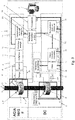
- the processing unit 8 comprises an electronic circuit comprising a first branch 8 ′ comprising a capacitor Cz, of which at least the impedance at 50 Hertz Zcz (50Hz) is greater than the impedance at 1000 Hertz Zcz (1000Hz), in series with at least one component whose impedance varies as a function of the voltage, preferably a diode D1.
- This component the impedance of which varies as a function of the voltage, preferably a diode D1 is provided to increase the time of tripping at 1000 Hertz, by influencing the value of the voltage Vtore for strong currents.
- adding this diode D1 alone also increases the tripping times to 50 Hertz for strong currents. This is why, it is necessary to combine the diode D1 in series with a capacitor Cz, preferentially located upstream of this one, whose impedance Zcz varies according to the frequency, so that the impedance at 50 Hertz Zcz (50Hz) is greater than the impedance at 1000 Hertz Zcz (1000Hz).
- Vtore 50Hz
- Vtore 1000Hz
- a voltage threshold is obtained which varies according to the frequency. It follows that in this configuration the device 1 provides a solution in accordance with the aforementioned standards, which does not need to be supplied by the network and which, moreover, is inexpensive, since only two electronic components are necessary for its implementation. .
- the diode D1 is a Zener diode, and this lets the current flow when the voltage across its terminals reaches the Zener voltage VZener, then maintains this voltage value VZener across its terminals.
- Vtore VZener + ZczxI
- I the intensity of the current passing through the first branch 8 '
- VD1 the voltage of the diode D1, I and VZener being constants
- the value of the Zener VZener voltage is 2.4 Volts.
- the diode D1 is a Transil diode.
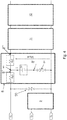
- this electronic circuit of the processing unit 8 may further comprise a second branch 8 "comprising a first resistor Rs1 connected to a first node NI of the first branch 8 'upstream of the latter ( figures 2 and 4 ).
- this first resistance Rs1 is intended to influence and adjust the difference between the amplitude at 50 Hertz and the amplitude at 1 kiloHertz for a given current.
- this electronic circuit of the processing unit 8 can further comprise a third branch 8 '"comprising a second resistor Rs2 connected to the first node NI downstream of the latter ( figures 2 and 4 ).
- This second resistance Rs2 is intended to influence and regulate the level of resistance of the 8/20 microsecond wave which is 5 kiloAmps for selective products.
- This electronic circuit of the processing unit 8 can be provided to be supplied by the fault signal coming from the measurement module 3.
- the first branch 8 ′ can be connected to the terminals 5a, 5b of the single winding secondary 5 or at the terminals 5c of the second secondary winding 5 ".
- This electronic circuit of the processing unit 8 can be provided to be supplied by the fault signal having undergone a pretreatment, for example by means of a filtering 9 described below.
- the detection and control module 6 further comprises a filtering circuit 9 for filtering a frequency bandwidth of the fault signal, connected to terminals 5a, 5b, 5c of said at least one secondary winding 5, 5 "between the measurement module 3 and the processing unit 8.
- the filtering circuit 9 makes it possible to control the bandwidth of the detection and control module 6.
- this bandwidth can be between 25 Hertz and 250 kiloHertz.
- the filtering circuit 9 is connected to terminals 5a, 5b of the single secondary winding 5.
- the filtering circuit 9 is connected to terminals 5a, 5b of said first secondary winding 5.
- the detection and control module 6 further comprises a protection element 10 against a strong fault current, for example the threshold may be between 1 Volt and 4 Volts depending on the number of turns of the torus 4, upstream of the processing unit 8.
- this protection element is provided to protect in particular the processing unit 8.
- This protective element 10 can consist of a Transil diode.
- the protection element 10 is electrically connected between the filtering circuit 9 and the processing unit 8.
- the protective element 10 is connected in parallel, downstream of the filtering circuit 9 and upstream of the processing unit 8.
- the protective element 10 is connected in parallel, upstream of the processing unit 8, on the one hand, to a terminal 5b which is connected to the filtering circuit 9 and, on the other hand, to a terminal 5c of the second secondary winding 5 ".
- the detection and control module 6 further comprises a voltage multiplier circuit 11 electrically connected downstream of the processing unit 8.
- the voltage multiplier circuit 11 is provided for multiplying the voltage of the incoming signal by a factor n.
- This factor n can, for example, be equal to 2 or 4 or 8.
- this configuration makes it possible to store the energy of the fault current, to decrease the volume of the toroid 4, which can be more compact, and to set the trigger times.
- the detection and control module 6 further comprises energy storage means 12 for controlling said actuator 7, electrically connected downstream of the voltage multiplier circuit 11.
- These energy storage means 12 are provided for storing the electrical energy necessary for actuating the actuator 7.
- the energy storage means 12 can for example consist of a capacitor.
- the detection and control module 6 may comprise a comparator circuit 13 disposed downstream of the energy storage means 12 and configured to compare said signal coming from the energy storage means 12 with a threshold value and conditionally delivering or selectively a control signal SC of the actuator 7, depending on the result of said comparison ( figures 1 and 3 ).
- the detection and control module 6 may include a control circuit 15 downstream of the comparator circuit 13 and upstream of the actuator 7 configured to control the actuator 7 from the control signal SC.
- This control circuit 15 may comprise a control member of the semiconductor type, such as a thyristor or a transistor.
- the device 1 can further comprise a detection and control module 6 ′ which is functionally active or operational for frequencies of the fault signal from 0 Hertz to a few tens of Hertz, this detection and control module 6 being supplied by the network.
- This detection and control module 6 ′ comprises a measurement module 3 ′ of a fault current configured to supply a fault signal proportional to the fault current in the event of a fault in the electrical installation comprising at least one toroid 4 ′ crossed by at least two of the conductors 2, 2 ', 2 ", N forming a primary winding and comprising at least one secondary winding 5' capable of providing the fault signal.
- This detection and control module 6 ′ may include a circuit 16 for excitation of the toroid 4 ′ comprising an alternating signal generator 17 producing a periodic carrier SPE, and, finally, a measurement winding 5 ′ suitable and intended to generate a fault signal resulting from the appearance of a differential fault in the network, said measurement winding 5 'being connected to circuits 18, 19, 20 for processing and evaluating the fault signal and transmitting a control signal SC 'for the actuator 7, the aforementioned circuits 18 to 20 being arranged to form an operational electronic chain belonging to the detection and control module 6' ( figures 1 and 3 ).
- the detection and control module 6 forms a DC module.
- the two detection and control modules 6 and 6 ′ are connected, at their output, via an OR circuit 14 to the single actuator 7 of the device 1.
- a device 1 comprising two modules 6 and 6 'in parallel and in competition is for example known from the document WO 2017/093670 of the plaintiff.
- the invention also relates to an electrical protection device.
- the electrical protection device is characterized in that it comprises the differential protection device according to the invention, as described above.
- the electrical protection device can consist of a differential switch or a type B or B + differential circuit breaker, preferably selective.
Landscapes
- Engineering & Computer Science (AREA)
- Power Engineering (AREA)
- Physics & Mathematics (AREA)
- General Physics & Mathematics (AREA)
- Emergency Protection Circuit Devices (AREA)
Applications Claiming Priority (1)
| Application Number | Priority Date | Filing Date | Title |
|---|---|---|---|
| FR1856437A FR3083926B1 (fr) | 2018-07-12 | 2018-07-12 | Dispositif de protection differentielle |
Publications (3)
| Publication Number | Publication Date |
|---|---|
| EP3594699A2 true EP3594699A2 (de) | 2020-01-15 |
| EP3594699A3 EP3594699A3 (de) | 2020-07-01 |
| EP3594699B1 EP3594699B1 (de) | 2023-11-01 |
Family
ID=63312158
Family Applications (1)
| Application Number | Title | Priority Date | Filing Date |
|---|---|---|---|
| EP19177898.4A Active EP3594699B1 (de) | 2018-07-12 | 2019-06-03 | Differentialschutzvorrichtung |
Country Status (3)
| Country | Link |
|---|---|
| EP (1) | EP3594699B1 (de) |
| FR (1) | FR3083926B1 (de) |
| PT (1) | PT3594699T (de) |
Cited By (3)
| Publication number | Priority date | Publication date | Assignee | Title |
|---|---|---|---|---|
| CN110120653A (zh) * | 2019-04-30 | 2019-08-13 | 天津大学 | 一种适用于对称双极直流线路的纵联行波差动保护方法 |
| EP4216386A1 (de) * | 2022-01-25 | 2023-07-26 | Legrand France | Schutzvorrichtung für eine elektrische anlage in wechselstrom und/oder gleichstrom |
| PL446907A1 (pl) * | 2023-11-30 | 2025-06-02 | Politechnika Gdańska | Układ wyłącznika różnicowoprądowego |
Citations (1)
| Publication number | Priority date | Publication date | Assignee | Title |
|---|---|---|---|---|
| WO2017093670A1 (fr) | 2015-12-03 | 2017-06-08 | Hager-Electro Sas (Société Par Actions Simplifiée) | Dispositif de protection différentielle du type b ou b+ comportant deux modules en parallèle et en concurrence |
Family Cites Families (8)
| Publication number | Priority date | Publication date | Assignee | Title |
|---|---|---|---|---|
| US3512045A (en) * | 1968-06-28 | 1970-05-12 | Gen Signal Corp | Ground fault responsive apparatus for electric power distribution apparatus |
| JP2710622B2 (ja) * | 1988-03-23 | 1998-02-10 | 河村電器産業株式会社 | 漏電ブレーカ |
| DE19937061A1 (de) * | 1999-08-05 | 2001-02-08 | Siemens Ag | Fehlerstrom-Schutzeinrichtung |
| DE19940344A1 (de) * | 1999-08-25 | 2001-03-01 | Siemens Ag | Schutzeinrichtung, insbesondere Fehlerstrom-Schutzeinrichtung |
| GB0607331D0 (en) * | 2006-04-12 | 2006-05-24 | Deepstream Technologies Ltd | Residual current device having voltage dependent and voltage independent modes of operation |
| EP2445074B1 (de) * | 2010-10-22 | 2017-03-29 | Shakira Limited | Fehlererkennungsvorrichtung für elektrische Einrichtungen und Ausrüstungen |
| DE102011011984B4 (de) * | 2011-02-22 | 2021-06-10 | Doepke Schaltgeräte GmbH | Fehlerstrom-Schutzeinrichtung mit frequenzabhängiger Schaltung zur Spannungsvervielfachung |
| FR3043270B1 (fr) * | 2015-10-29 | 2021-04-30 | Hager Electro Sas | Dispositif de protection differentielle avec une fonction coupe-feu |
-
2018
- 2018-07-12 FR FR1856437A patent/FR3083926B1/fr active Active
-
2019
- 2019-06-03 PT PT191778984T patent/PT3594699T/pt unknown
- 2019-06-03 EP EP19177898.4A patent/EP3594699B1/de active Active
Patent Citations (1)
| Publication number | Priority date | Publication date | Assignee | Title |
|---|---|---|---|---|
| WO2017093670A1 (fr) | 2015-12-03 | 2017-06-08 | Hager-Electro Sas (Société Par Actions Simplifiée) | Dispositif de protection différentielle du type b ou b+ comportant deux modules en parallèle et en concurrence |
Cited By (5)
| Publication number | Priority date | Publication date | Assignee | Title |
|---|---|---|---|---|
| CN110120653A (zh) * | 2019-04-30 | 2019-08-13 | 天津大学 | 一种适用于对称双极直流线路的纵联行波差动保护方法 |
| EP4216386A1 (de) * | 2022-01-25 | 2023-07-26 | Legrand France | Schutzvorrichtung für eine elektrische anlage in wechselstrom und/oder gleichstrom |
| FR3132184A1 (fr) * | 2022-01-25 | 2023-07-28 | Legrand France | Appareil électrique de protection d’une installation électrique en courants alternatif et/ou continu |
| PL446907A1 (pl) * | 2023-11-30 | 2025-06-02 | Politechnika Gdańska | Układ wyłącznika różnicowoprądowego |
| PL249165B1 (pl) * | 2023-11-30 | 2026-03-09 | Politechnika Gdanska | Układ wyłącznika różnicowoprądowego |
Also Published As
| Publication number | Publication date |
|---|---|
| FR3083926B1 (fr) | 2021-08-06 |
| FR3083926A1 (fr) | 2020-01-17 |
| PT3594699T (pt) | 2024-01-23 |
| EP3594699A3 (de) | 2020-07-01 |
| EP3594699B1 (de) | 2023-11-01 |
Similar Documents
| Publication | Publication Date | Title |
|---|---|---|
| EP0407310B1 (de) | Festkörperauslöser mit einer Desensibilisierungsvorrichtung für den Erdschutz | |
| FR2694142A1 (fr) | Disjoncteur de protection contre des défauts à la terre. | |
| EP3594699B1 (de) | Differentialschutzvorrichtung | |
| FR2942352B1 (fr) | Identification et protection d'un systeme de courant c.a-c.c aerospatial en presence de contenu de courant c.c en raison des charges defectueuses | |
| EP3577672B1 (de) | Hochspannungsgleichstromunterbrechungsvorrichtung | |
| FR2863115A1 (fr) | Interrupteur de circuit en cas de defaut a la terre. | |
| EP3561523B1 (de) | Elektrische vorrichtung, die mittel zum prüfen eines prüfbaren stromwandlers umfasst | |
| EP3300541B1 (de) | Differentialschutzvorrichtung mit brandschutzfunktion | |
| FR3055495A1 (fr) | Procede et dispositif de circuit pour couper une source de tension d'au moins un consommateur | |
| FR3073660A1 (fr) | Liaison electrique comprenant un dispositif de protection electrique. | |
| EP0936716B1 (de) | Differentialschutz | |
| EP0180506B1 (de) | Sicherheitseinrichtung für Differenzstromschutzgerät | |
| EP2980941B1 (de) | Vorrichtung zum anpassen eines elektrischen stromversorgungssignals, entsprechendes stromversorgungssystem und verfahren zur anpassung des stromversorgungssignals | |
| CA1227832A (fr) | Appareil de detection de la defaillance d'une alimentation electrique a decoupage | |
| EP3832687A1 (de) | In reihe geschaltete zweistufige elektrische schutzvorrichtungen | |
| EP3883077B1 (de) | Geräte zum elektrischen schutz und entsprechende verfahren | |
| FR3116392A1 (fr) | Appareillage de protection à coupure électronique | |
| EP0813283B1 (de) | Gegen unbeabsichtigtes Auslösen immunisiertes Differentialschutz | |
| EP3139485B1 (de) | Progressives anlassverfahren eines elektromotors | |
| EP1003263B1 (de) | Differentialschutz | |
| EP4586297A1 (de) | Elektrische schutzvorrichtung und steuerungsverfahren dafür | |
| EP4661230A1 (de) | Schutzschaltung für ein dreiphasiges stromversorgungssystem | |
| EP1279084B1 (de) | Spannungsadaptereinheit | |
| WO2024209145A1 (fr) | Système et méthode de protection d'un système électronique d'actionnement contre un sur-courant | |
| EP3300540B1 (de) | Differentialschutzvorrichtung mit mitteln zum isolieren eines relais oder analoga |
Legal Events
| Date | Code | Title | Description |
|---|---|---|---|
| PUAI | Public reference made under article 153(3) epc to a published international application that has entered the european phase |
Free format text: ORIGINAL CODE: 0009012 |
|
| STAA | Information on the status of an ep patent application or granted ep patent |
Free format text: STATUS: THE APPLICATION HAS BEEN PUBLISHED |
|
| AK | Designated contracting states |
Kind code of ref document: A2 Designated state(s): AL AT BE BG CH CY CZ DE DK EE ES FI FR GB GR HR HU IE IS IT LI LT LU LV MC MK MT NL NO PL PT RO RS SE SI SK SM TR |
|
| AX | Request for extension of the european patent |
Extension state: BA ME |
|
| PUAL | Search report despatched |
Free format text: ORIGINAL CODE: 0009013 |
|
| PUAF | Information related to the publication of a search report (a3 document) modified or deleted |
Free format text: ORIGINAL CODE: 0009199SEPU |
|
| AK | Designated contracting states |
Kind code of ref document: A3 Designated state(s): AL AT BE BG CH CY CZ DE DK EE ES FI FR GB GR HR HU IE IS IT LI LT LU LV MC MK MT NL NO PL PT RO RS SE SI SK SM TR |
|
| AX | Request for extension of the european patent |
Extension state: BA ME |
|
| RIC1 | Information provided on ipc code assigned before grant |
Ipc: H02H 3/33 20060101ALI20200420BHEP Ipc: H02H 1/06 20060101ALI20200420BHEP Ipc: H02H 9/04 20060101ALI20200420BHEP Ipc: G01R 19/10 20060101ALI20200420BHEP Ipc: H02H 3/347 20060101ALI20200420BHEP Ipc: G01R 19/00 20060101AFI20200420BHEP |
|
| PUAL | Search report despatched |
Free format text: ORIGINAL CODE: 0009013 |
|
| D17D | Deferred search report published (deleted) | ||
| RIC1 | Information provided on ipc code assigned before grant |
Ipc: H02H 1/06 20060101ALI20200520BHEP Ipc: H02H 3/33 20060101ALI20200520BHEP Ipc: H02H 9/04 20060101ALI20200520BHEP Ipc: G01R 19/00 20060101AFI20200520BHEP Ipc: H02H 3/347 20060101ALI20200520BHEP Ipc: G01R 19/10 20060101ALI20200520BHEP |
|
| AK | Designated contracting states |
Kind code of ref document: A3 Designated state(s): AL AT BE BG CH CY CZ DE DK EE ES FI FR GB GR HR HU IE IS IT LI LT LU LV MC MK MT NL NO PL PT RO RS SE SI SK SM TR |
|
| AX | Request for extension of the european patent |
Extension state: BA ME |
|
| STAA | Information on the status of an ep patent application or granted ep patent |
Free format text: STATUS: REQUEST FOR EXAMINATION WAS MADE |
|
| 17P | Request for examination filed |
Effective date: 20201228 |
|
| RBV | Designated contracting states (corrected) |
Designated state(s): AL AT BE BG CH CY CZ DE DK EE ES FI FR GB GR HR HU IE IS IT LI LT LU LV MC MK MT NL NO PL PT RO RS SE SI SK SM TR |
|
| STAA | Information on the status of an ep patent application or granted ep patent |
Free format text: STATUS: EXAMINATION IS IN PROGRESS |
|
| 17Q | First examination report despatched |
Effective date: 20220518 |
|
| GRAP | Despatch of communication of intention to grant a patent |
Free format text: ORIGINAL CODE: EPIDOSNIGR1 |
|
| STAA | Information on the status of an ep patent application or granted ep patent |
Free format text: STATUS: GRANT OF PATENT IS INTENDED |
|
| INTG | Intention to grant announced |
Effective date: 20230516 |
|
| P01 | Opt-out of the competence of the unified patent court (upc) registered |
Effective date: 20230606 |
|
| GRAS | Grant fee paid |
Free format text: ORIGINAL CODE: EPIDOSNIGR3 |
|
| GRAA | (expected) grant |
Free format text: ORIGINAL CODE: 0009210 |
|
| STAA | Information on the status of an ep patent application or granted ep patent |
Free format text: STATUS: THE PATENT HAS BEEN GRANTED |
|
| AK | Designated contracting states |
Kind code of ref document: B1 Designated state(s): AL AT BE BG CH CY CZ DE DK EE ES FI FR GB GR HR HU IE IS IT LI LT LU LV MC MK MT NL NO PL PT RO RS SE SI SK SM TR |
|
| REG | Reference to a national code |
Ref country code: GB Ref legal event code: FG4D Free format text: NOT ENGLISH |
|
| REG | Reference to a national code |
Ref country code: CH Ref legal event code: EP |
|
| REG | Reference to a national code |
Ref country code: IE Ref legal event code: FG4D Free format text: LANGUAGE OF EP DOCUMENT: FRENCH |
|
| REG | Reference to a national code |
Ref country code: DE Ref legal event code: R096 Ref document number: 602019040418 Country of ref document: DE |
|
| REG | Reference to a national code |
Ref country code: PT Ref legal event code: SC4A Ref document number: 3594699 Country of ref document: PT Date of ref document: 20240123 Kind code of ref document: T Free format text: AVAILABILITY OF NATIONAL TRANSLATION Effective date: 20240116 |
|
| REG | Reference to a national code |
Ref country code: NL Ref legal event code: FP |
|
| REG | Reference to a national code |
Ref country code: SE Ref legal event code: TRGR |
|
| REG | Reference to a national code |
Ref country code: LT Ref legal event code: MG9D |
|
| PG25 | Lapsed in a contracting state [announced via postgrant information from national office to epo] |
Ref country code: GR Free format text: LAPSE BECAUSE OF FAILURE TO SUBMIT A TRANSLATION OF THE DESCRIPTION OR TO PAY THE FEE WITHIN THE PRESCRIBED TIME-LIMIT Effective date: 20240202 |
|
| PG25 | Lapsed in a contracting state [announced via postgrant information from national office to epo] |
Ref country code: IS Free format text: LAPSE BECAUSE OF FAILURE TO SUBMIT A TRANSLATION OF THE DESCRIPTION OR TO PAY THE FEE WITHIN THE PRESCRIBED TIME-LIMIT Effective date: 20240301 |
|
| PG25 | Lapsed in a contracting state [announced via postgrant information from national office to epo] |
Ref country code: LT Free format text: LAPSE BECAUSE OF FAILURE TO SUBMIT A TRANSLATION OF THE DESCRIPTION OR TO PAY THE FEE WITHIN THE PRESCRIBED TIME-LIMIT Effective date: 20231101 |
|
| PG25 | Lapsed in a contracting state [announced via postgrant information from national office to epo] |
Ref country code: ES Free format text: LAPSE BECAUSE OF FAILURE TO SUBMIT A TRANSLATION OF THE DESCRIPTION OR TO PAY THE FEE WITHIN THE PRESCRIBED TIME-LIMIT Effective date: 20231101 |
|
| PG25 | Lapsed in a contracting state [announced via postgrant information from national office to epo] |
Ref country code: LT Free format text: LAPSE BECAUSE OF FAILURE TO SUBMIT A TRANSLATION OF THE DESCRIPTION OR TO PAY THE FEE WITHIN THE PRESCRIBED TIME-LIMIT Effective date: 20231101 Ref country code: IS Free format text: LAPSE BECAUSE OF FAILURE TO SUBMIT A TRANSLATION OF THE DESCRIPTION OR TO PAY THE FEE WITHIN THE PRESCRIBED TIME-LIMIT Effective date: 20240301 Ref country code: GR Free format text: LAPSE BECAUSE OF FAILURE TO SUBMIT A TRANSLATION OF THE DESCRIPTION OR TO PAY THE FEE WITHIN THE PRESCRIBED TIME-LIMIT Effective date: 20240202 Ref country code: ES Free format text: LAPSE BECAUSE OF FAILURE TO SUBMIT A TRANSLATION OF THE DESCRIPTION OR TO PAY THE FEE WITHIN THE PRESCRIBED TIME-LIMIT Effective date: 20231101 Ref country code: BG Free format text: LAPSE BECAUSE OF FAILURE TO SUBMIT A TRANSLATION OF THE DESCRIPTION OR TO PAY THE FEE WITHIN THE PRESCRIBED TIME-LIMIT Effective date: 20240201 |
|
| PG25 | Lapsed in a contracting state [announced via postgrant information from national office to epo] |
Ref country code: RS Free format text: LAPSE BECAUSE OF FAILURE TO SUBMIT A TRANSLATION OF THE DESCRIPTION OR TO PAY THE FEE WITHIN THE PRESCRIBED TIME-LIMIT Effective date: 20231101 Ref country code: PL Free format text: LAPSE BECAUSE OF FAILURE TO SUBMIT A TRANSLATION OF THE DESCRIPTION OR TO PAY THE FEE WITHIN THE PRESCRIBED TIME-LIMIT Effective date: 20231101 Ref country code: NO Free format text: LAPSE BECAUSE OF FAILURE TO SUBMIT A TRANSLATION OF THE DESCRIPTION OR TO PAY THE FEE WITHIN THE PRESCRIBED TIME-LIMIT Effective date: 20240201 Ref country code: LV Free format text: LAPSE BECAUSE OF FAILURE TO SUBMIT A TRANSLATION OF THE DESCRIPTION OR TO PAY THE FEE WITHIN THE PRESCRIBED TIME-LIMIT Effective date: 20231101 Ref country code: HR Free format text: LAPSE BECAUSE OF FAILURE TO SUBMIT A TRANSLATION OF THE DESCRIPTION OR TO PAY THE FEE WITHIN THE PRESCRIBED TIME-LIMIT Effective date: 20231101 |
|
| PG25 | Lapsed in a contracting state [announced via postgrant information from national office to epo] |
Ref country code: DK Free format text: LAPSE BECAUSE OF FAILURE TO SUBMIT A TRANSLATION OF THE DESCRIPTION OR TO PAY THE FEE WITHIN THE PRESCRIBED TIME-LIMIT Effective date: 20231101 |
|
| PG25 | Lapsed in a contracting state [announced via postgrant information from national office to epo] |
Ref country code: CZ Free format text: LAPSE BECAUSE OF FAILURE TO SUBMIT A TRANSLATION OF THE DESCRIPTION OR TO PAY THE FEE WITHIN THE PRESCRIBED TIME-LIMIT Effective date: 20231101 |
|
| PG25 | Lapsed in a contracting state [announced via postgrant information from national office to epo] |
Ref country code: SK Free format text: LAPSE BECAUSE OF FAILURE TO SUBMIT A TRANSLATION OF THE DESCRIPTION OR TO PAY THE FEE WITHIN THE PRESCRIBED TIME-LIMIT Effective date: 20231101 |
|
| PG25 | Lapsed in a contracting state [announced via postgrant information from national office to epo] |
Ref country code: SM Free format text: LAPSE BECAUSE OF FAILURE TO SUBMIT A TRANSLATION OF THE DESCRIPTION OR TO PAY THE FEE WITHIN THE PRESCRIBED TIME-LIMIT Effective date: 20231101 Ref country code: SK Free format text: LAPSE BECAUSE OF FAILURE TO SUBMIT A TRANSLATION OF THE DESCRIPTION OR TO PAY THE FEE WITHIN THE PRESCRIBED TIME-LIMIT Effective date: 20231101 Ref country code: EE Free format text: LAPSE BECAUSE OF FAILURE TO SUBMIT A TRANSLATION OF THE DESCRIPTION OR TO PAY THE FEE WITHIN THE PRESCRIBED TIME-LIMIT Effective date: 20231101 Ref country code: DK Free format text: LAPSE BECAUSE OF FAILURE TO SUBMIT A TRANSLATION OF THE DESCRIPTION OR TO PAY THE FEE WITHIN THE PRESCRIBED TIME-LIMIT Effective date: 20231101 Ref country code: CZ Free format text: LAPSE BECAUSE OF FAILURE TO SUBMIT A TRANSLATION OF THE DESCRIPTION OR TO PAY THE FEE WITHIN THE PRESCRIBED TIME-LIMIT Effective date: 20231101 |
|
| REG | Reference to a national code |
Ref country code: DE Ref legal event code: R097 Ref document number: 602019040418 Country of ref document: DE |
|
| PLBE | No opposition filed within time limit |
Free format text: ORIGINAL CODE: 0009261 |
|
| STAA | Information on the status of an ep patent application or granted ep patent |
Free format text: STATUS: NO OPPOSITION FILED WITHIN TIME LIMIT |
|
| 26N | No opposition filed |
Effective date: 20240802 |
|
| PG25 | Lapsed in a contracting state [announced via postgrant information from national office to epo] |
Ref country code: SI Free format text: LAPSE BECAUSE OF FAILURE TO SUBMIT A TRANSLATION OF THE DESCRIPTION OR TO PAY THE FEE WITHIN THE PRESCRIBED TIME-LIMIT Effective date: 20231101 |
|
| PG25 | Lapsed in a contracting state [announced via postgrant information from national office to epo] |
Ref country code: SI Free format text: LAPSE BECAUSE OF FAILURE TO SUBMIT A TRANSLATION OF THE DESCRIPTION OR TO PAY THE FEE WITHIN THE PRESCRIBED TIME-LIMIT Effective date: 20231101 |
|
| PG25 | Lapsed in a contracting state [announced via postgrant information from national office to epo] |
Ref country code: MC Free format text: LAPSE BECAUSE OF FAILURE TO SUBMIT A TRANSLATION OF THE DESCRIPTION OR TO PAY THE FEE WITHIN THE PRESCRIBED TIME-LIMIT Effective date: 20231101 |
|
| PG25 | Lapsed in a contracting state [announced via postgrant information from national office to epo] |
Ref country code: LU Free format text: LAPSE BECAUSE OF NON-PAYMENT OF DUE FEES Effective date: 20240603 |
|
| PG25 | Lapsed in a contracting state [announced via postgrant information from national office to epo] |
Ref country code: IE Free format text: LAPSE BECAUSE OF NON-PAYMENT OF DUE FEES Effective date: 20240603 |
|
| PG25 | Lapsed in a contracting state [announced via postgrant information from national office to epo] |
Ref country code: BE Free format text: LAPSE BECAUSE OF NON-PAYMENT OF DUE FEES Effective date: 20240630 |
|
| REG | Reference to a national code |
Ref country code: BE Ref legal event code: MM Effective date: 20240630 |
|
| PGFP | Annual fee paid to national office [announced via postgrant information from national office to epo] |
Ref country code: DE Payment date: 20250627 Year of fee payment: 7 |
|
| PGFP | Annual fee paid to national office [announced via postgrant information from national office to epo] |
Ref country code: GB Payment date: 20250627 Year of fee payment: 7 |
|
| PGFP | Annual fee paid to national office [announced via postgrant information from national office to epo] |
Ref country code: NL Payment date: 20250626 Year of fee payment: 7 |
|
| PGFP | Annual fee paid to national office [announced via postgrant information from national office to epo] |
Ref country code: PT Payment date: 20250520 Year of fee payment: 7 |
|
| PGFP | Annual fee paid to national office [announced via postgrant information from national office to epo] |
Ref country code: FR Payment date: 20250625 Year of fee payment: 7 |
|
| PGFP | Annual fee paid to national office [announced via postgrant information from national office to epo] |
Ref country code: AT Payment date: 20250521 Year of fee payment: 7 |
|
| PGFP | Annual fee paid to national office [announced via postgrant information from national office to epo] |
Ref country code: SE Payment date: 20250627 Year of fee payment: 7 |
|
| PG25 | Lapsed in a contracting state [announced via postgrant information from national office to epo] |
Ref country code: CY Free format text: LAPSE BECAUSE OF FAILURE TO SUBMIT A TRANSLATION OF THE DESCRIPTION OR TO PAY THE FEE WITHIN THE PRESCRIBED TIME-LIMIT; INVALID AB INITIO Effective date: 20190603 |
|
| PG25 | Lapsed in a contracting state [announced via postgrant information from national office to epo] |
Ref country code: FI Free format text: LAPSE BECAUSE OF FAILURE TO SUBMIT A TRANSLATION OF THE DESCRIPTION OR TO PAY THE FEE WITHIN THE PRESCRIBED TIME-LIMIT Effective date: 20231101 |
|
| PGFP | Annual fee paid to national office [announced via postgrant information from national office to epo] |
Ref country code: IT Payment date: 20250619 Year of fee payment: 7 |
|
| PGFP | Annual fee paid to national office [announced via postgrant information from national office to epo] |
Ref country code: CH Payment date: 20250701 Year of fee payment: 7 |
|
| PG25 | Lapsed in a contracting state [announced via postgrant information from national office to epo] |
Ref country code: RO Free format text: LAPSE BECAUSE OF FAILURE TO SUBMIT A TRANSLATION OF THE DESCRIPTION OR TO PAY THE FEE WITHIN THE PRESCRIBED TIME-LIMIT Effective date: 20231101 |
|
| PG25 | Lapsed in a contracting state [announced via postgrant information from national office to epo] |
Ref country code: HU Free format text: LAPSE BECAUSE OF FAILURE TO SUBMIT A TRANSLATION OF THE DESCRIPTION OR TO PAY THE FEE WITHIN THE PRESCRIBED TIME-LIMIT; INVALID AB INITIO Effective date: 20190603 |
|
| REG | Reference to a national code |
Ref country code: AT Ref legal event code: UEP Ref document number: 1627793 Country of ref document: AT Kind code of ref document: T Effective date: 20231101 |