EP3594893A1 - Dispositif de traitement d'informations, procédé de traitement d'informations et programme - Google Patents
Dispositif de traitement d'informations, procédé de traitement d'informations et programme Download PDFInfo
- Publication number
- EP3594893A1 EP3594893A1 EP17899352.3A EP17899352A EP3594893A1 EP 3594893 A1 EP3594893 A1 EP 3594893A1 EP 17899352 A EP17899352 A EP 17899352A EP 3594893 A1 EP3594893 A1 EP 3594893A1
- Authority
- EP
- European Patent Office
- Prior art keywords
- user
- comfort
- degree
- particular user
- information processing
- Prior art date
- Legal status (The legal status is an assumption and is not a legal conclusion. Google has not performed a legal analysis and makes no representation as to the accuracy of the status listed.)
- Withdrawn
Links
Images


Classifications
-
- G—PHYSICS
- G06—COMPUTING OR CALCULATING; COUNTING
- G06Q—INFORMATION AND COMMUNICATION TECHNOLOGY [ICT] SPECIALLY ADAPTED FOR ADMINISTRATIVE, COMMERCIAL, FINANCIAL, MANAGERIAL OR SUPERVISORY PURPOSES; SYSTEMS OR METHODS SPECIALLY ADAPTED FOR ADMINISTRATIVE, COMMERCIAL, FINANCIAL, MANAGERIAL OR SUPERVISORY PURPOSES, NOT OTHERWISE PROVIDED FOR
- G06Q50/00—Information and communication technology [ICT] specially adapted for implementation of business processes of specific business sectors, e.g. utilities or tourism
- G06Q50/40—Business processes related to the transportation industry
-
- B—PERFORMING OPERATIONS; TRANSPORTING
- B61—RAILWAYS
- B61L—GUIDING RAILWAY TRAFFIC; ENSURING THE SAFETY OF RAILWAY TRAFFIC
- B61L15/00—Indicators provided on the vehicle or train for signalling purposes
- B61L15/0072—On-board train data handling
-
- B—PERFORMING OPERATIONS; TRANSPORTING
- B61—RAILWAYS
- B61L—GUIDING RAILWAY TRAFFIC; ENSURING THE SAFETY OF RAILWAY TRAFFIC
- B61L25/00—Recording or indicating positions or identities of vehicles or trains or setting of track apparatus
- B61L25/02—Indicating or recording positions or identities of vehicles or trains
- B61L25/025—Absolute localisation, e.g. providing geodetic coordinates
-
- G—PHYSICS
- G01—MEASURING; TESTING
- G01G—WEIGHING
- G01G19/00—Weighing apparatus or methods adapted for special purposes not provided for in the preceding groups
- G01G19/44—Weighing apparatus or methods adapted for special purposes not provided for in the preceding groups for weighing persons
-
- H—ELECTRICITY
- H04—ELECTRIC COMMUNICATION TECHNIQUE
- H04L—TRANSMISSION OF DIGITAL INFORMATION, e.g. TELEGRAPHIC COMMUNICATION
- H04L67/00—Network arrangements or protocols for supporting network services or applications
- H04L67/01—Protocols
- H04L67/12—Protocols specially adapted for proprietary or special-purpose networking environments, e.g. medical networks, sensor networks, networks in vehicles or remote metering networks
Definitions
- the present disclosure relates to an information processing apparatus, an information processing method, and a program.
- a user wants to learn the degree of comfort of an area different from the area where the user is located (hereinafter, also referred to as "another area"). For example, there is a demand that the user wants to learn where the area is, of which the degree of comfort is higher than the degree of comfort of the area where the user is located. In a case where the user learns an area with a higher degree of comfort, for example, the user can move to the area with a higher degree of comfort.
- Patent Document 1 Japanese Patent Application Laid-Open No. 2015-36836
- an information processing apparatus including: a comfort degree calculation unit that calculates a degree of comfort of a particular user on the basis of sensor data of another user; and an output control unit that controls such that information regarding the degree of comfort is output to a terminal of the particular user.
- an information processing method including: calculating a degree of comfort of a particular user on the basis of sensor data of another user; and controlling, by a processor, such that information regarding the degree of comfort is output to a terminal of the particular user.
- a program causing a computer to function as an information processing apparatus including: a comfort degree calculation unit that calculates a degree of comfort of a particular user on the basis of sensor data of another user; and an output control unit that controls such that information regarding the degree of comfort is output to a terminal of the particular user.
- the present disclosure there is provided a technology capable of improving the accuracy of the degree of comfort in another area to be learned by a user.
- the above-mentioned effect is not necessarily limited, and any effects indicated in the present description or other effects that can be learned from the present description may be exhibited together with the above-mentioned effect or instead of the above-mentioned effect.
- a plurality of constituent elements having substantially the same or equivalent functional configuration is sometimes distinguished by attaching different numerals after the same reference numeral.
- first the same reference numeral is attached.
- equivalent constituent elements of different embodiments are sometimes distinguished by attaching different alphabets after the same reference numeral.
- only the same reference numeral is attached.
- a user wants to learn the degree of comfort of an area different from the area where the user is located (another area). For example, there is a demand that the user wants to learn where the area is, of which the degree of comfort is higher than the degree of comfort of the area where the user is located. In a case where the user learns an area with a higher degree of comfort, for example, the user can move to the area with a higher degree of comfort.
- the present description it is desired to provide a technology capable of improving the accuracy of the degree of comfort in another area to be learned by the user. Furthermore, the present description will propose a technology for finding out a position with a higher degree of comfort according to a plurality of environmental parameters and a situation in which the user is placed, and also automatically updating the method of finding out the degree of comfort depending on the result of the user's behavior. Moreover, the present description will propose a technology that can follow a position with a higher degree of comfort even in a case where the position with a high degree of comfort changes every moment.
- a user located at a platform of a station is notified of movement to a more comfortable car.
- a car of a train is mentioned as an example of an area where a user is located, the area where a user is located is not limited to the car of the train.
- Fig. 1 is a diagram for explaining an example in which a user located at a platform of a station is notified of movement to a more comfortable car. As illustrated in Fig. 1 , a case where a train made up of a plurality of cars is traveling toward a station ST is assumed. A user U0 is waiting for a train at a platform of the station ST. Furthermore, users U1 to U5 are riding on the train.
- the number of cars is six, but the number of cars is not limited.
- the user U1 is on board the leading car
- the user U2 is on board the third car
- the user U3 is on board the fourth car
- the user U4 is on board the fifth car
- the user U5 is on board the sixth car; however, the number of users riding on the train is not limited.
- the user U0 wears a sensor apparatus (hereinafter also referred to as "detection apparatus") 20-0.
- Fig. 1 illustrates a case where the detection apparatus 20-0 is a bracelet.
- the form of the detection apparatus 20-0 is not particularly limited.
- the form of the detection apparatus 20-0 may be a necklace type, a head-mounted type, or a glasses type.
- the detection apparatus 20-0 may be contained in a terminal held by the user U0 (hereinafter also referred to as "presentation apparatus").
- the users U1 to U5 wear detection apparatuses 20-1 to 20-5.
- the detection apparatuses 20-0 to 20-5 have sensors. In the following, an example in which the detection apparatuses 20-0 to 20-5 have position sensors, temperature sensors, humidity sensors, odor sensors, sound sensors, and CO 2 sensors will be mainly described. However, the types of sensors included in the detection apparatuses 20-0 to 20-5 are not limited.
- the detection apparatuses 20-0 to 20-5 each transmit sensor data (hereinafter also referred to as "sensor output values") obtained by the sensors via a network 931 (for example, every predetermined time) to an information processing apparatus (hereinafter also referred to as "server") 10 (S0 to S5).
- the degree of comfort of the user U0 in each car is calculated on the basis of the sensor output values obtained from the detection apparatuses 20-0 to 20-5. Then, information regarding the degree of comfort of the user U0 in each car is notified from the server 10 to the presentation apparatus 30 of the user U0 via the network 931 (S0). At this time, in a case where there is a car having a higher degree of comfort than a car expected to be boarded by the user U0, the car having the higher degree is notified from the server 10 to the presentation apparatus 30 of the user U0.
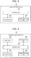
- FIG. 2 is a block diagram illustrating a functional configuration example of the server 10 according to the embodiment of the present disclosure.
- the server 10 includes a control unit 110, a storage unit 130, and a communication unit 140.
- these functional blocks included in the server 10 will be described.
- the control unit 110 executes control of each unit of the server 10.
- the control unit 110 may be configured from one or a plurality of processing units such as central processing units (CPUs).
- CPUs central processing units
- this processing unit may be configured from an electronic circuit.
- the control unit 110 has a data acquisition unit 112, a comfort degree calculation unit 113, and an output control unit 114. These blocks included in the control unit 110 will be described in detail later.
- the storage unit 130 is configured with a memory included and is a recording device that stores a program executed by the control unit 110 and stores data necessary for the execution of the program. Furthermore, the storage unit 130 temporarily stores data for computation by the control unit 110. Note that the storage unit 130 may be a magnetic storage unit device, a semiconductor storing device, an optical storing device, or a magneto-optical storing device.
- the communication unit 140 is configured with a communication circuit included and has a function of communicating with another apparatus via the network 931 ( Fig. 1 ).
- the communication unit 140 is configured from a communication interface.
- the communication unit 140 is capable of communicating with the detection apparatus 20 and the presentation apparatus 30 via the network 931 ( Fig. 1 ).
- FIG. 3 is a block diagram illustrating a functional configuration example of the detection apparatus 20 according to the embodiment of the present disclosure.
- the detection apparatus 20 includes a control unit 210, a storage unit 230, and a communication unit 240 in addition to the above-described sensors.
- these functional blocks included in the detection apparatus 20 will be described.
- the control unit 210 executes control of each unit of the detection apparatus 20.
- the control unit 210 may be configured from one or a plurality of processing units such as central processing units (CPUs).
- CPUs central processing units
- this processing unit may be configured from an electronic circuit.
- the storage unit 230 is configured with a memory included and is a recording device that stores a program executed by the control unit 210 and stores data necessary for the execution of the program. Furthermore, the storage unit 230 temporarily stores data for computation by the control unit 210. Note that the storage unit 230 may be a magnetic storage unit device, a semiconductor storing device, an optical storing device, or a magneto-optical storing device.
- the communication unit 240 is configured with a communication circuit included and has a function of communicating with another apparatus via the network 931 ( Fig. 1 ).
- the communication unit 240 is configured from a communication interface.
- the communication unit 240 is capable of communicating with the server 10 via the network 931 ( Fig. 1 ).
- the communication unit 240 may be capable of communicating with the server 10 via a terminal.
- FIG. 4 is a block diagram illustrating a functional configuration example of the presentation apparatus 30 according to the embodiment of the present disclosure.
- the presentation apparatus 30 includes a control unit 310, an input unit 320, a storage unit 330, a communication unit 340, and a presentation unit 350.
- these functional blocks included in the presentation apparatus 30 will be described.
- the control unit 310 executes control of each unit of the presentation apparatus 30.
- the control unit 310 may be configured from one or a plurality of processing units such as central processing units (CPUs).
- CPUs central processing units
- this processing unit may be configured from an electronic circuit.
- the input unit 320 has a function of accepting an input of an operation by the user U0.
- the input unit 320 may include a mouse, a keyboard, a touch panel, a switch, a lever, and the like.
- the input unit 320 may include a microphone that detects the voice of the user U0.
- the storage unit 330 is configured with a memory included and is a recording device that stores a program executed by the control unit 310 and stores data necessary for the execution of the program. Furthermore, the storage unit 330 temporarily stores data for computation by the control unit 310. Note that the storage unit 330 may be a magnetic storage unit device, a semiconductor storing device, an optical storing device, or a magneto-optical storing device.
- the communication unit 340 is configured with a communication circuit included and has a function of communicating with another apparatus via the network 931 ( Fig. 1 ).
- the communication unit 240 is configured from a communication interface.
- the communication unit 340 is capable of communicating with the server 10 via the network 931 ( Fig. 1 ).
- the presentation unit 350 outputs various types of information.
- the presentation unit 350 may include a display capable of providing a view that can be visually recognized by the user U0, and the display may be a liquid crystal display or an organic electro-luminescence (EL) display.
- the presentation unit 350 may include a voice output apparatus such as a speaker.
- the presentation unit 350 may include a tactile presentation apparatus that presents a tactile sensation to the user U0.
- a technique of calculating the type of train and the immediately previous stop station in the server 10, on the basis of the movement history of each user and information regarding the train will be described.
- the type of train is information that specifies a train and is generally called "train number”.
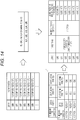
- Fig. 5 is a diagram for explaining a technique of calculating the type of a train expected to be boarded by the user U0 and an immediately previous stop station of the train.
- the data acquisition unit 112 acquires sensor output values of the respective users.
- position information on each user acquired by the data acquisition unit 112 is accumulated in the server 10 as the movement history of each user.
- the movement history of the user U0 contains a position P0 of the user U0 at time T0.
- the information regarding the train includes stop stations and station positions for each train line (for example, an Y1 line bound for a Z1 direction or the like).
- the information regarding the train includes the departure time of each train at each station.
- the comfort degree calculation unit 113 can detect that the user U0 is located at the matched station, on the basis of the position information on the user U0 and the station position. Then, on the basis of the movement history, the comfort degree calculation unit 113 can specify a user group closest to the user U0, from among user groups near the user U0. In the example illustrated in Fig. 5 , the comfort degree calculation unit 113 specifies the users U1 to U5 as such a user group.
- the comfort degree calculation unit 113 can specify the type of a train in which the users U1 to U5 are located and the immediately previous stop station, on the basis of the station position, the departure time, and the movement history of each user.
- the type of the train in which the users U1 to U5 are located is specified as "Y1 line bound for Z1 direction, leaving from X12 station at 12:15".
- the comfort degree calculation unit 113 may calculate the arrival time of the train in which the users U1 to U5 are located, from map (latitude and longitude) information on the route and the moving speeds of the users U1 to U5, to calculate the departure time on the basis of the calculation result.
- the immediately previous stop station of the users U1 to U5 is specified as "X11 station”.
- the comfort degree calculation unit 113 can specify the latest position information on the user U0 located at the station ST as an expected boarding position.
- the comfort degree calculation unit 113 can also specify an expected boarding station as "X12 station" on the basis of the latest position information on the user U0 located at the station ST and the station position.
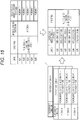
- Fig. 6 is a diagram for explaining a technique of specifying the located car of each user at the stop station.
- the information regarding the train includes the stop position of each car at each station for each train line (for example, the Y1 line bound for the Z1 direction or the like). Therefore, in the server 10, the comfort degree calculation unit 113 can specify the located car of each user at the stop station on the basis of the located position of each user at the immediately previous stop station and the stop position of each car at the station.
- Fig. 7 is a diagram for explaining a calculation example of the degree of comfort of the user U0 in each car.
- the comfort degree calculation unit 113 calculates the degree of comfort of the user U0 on the basis of the sensor output values of the users U1 to U5. Then, the output control unit 114 controls such that the calculated degree of comfort (or information regarding the degree of comfort) is output to the presentation apparatus 30 of the user U0 via the communication unit 140.
- a weight and a comfort range are associated with the user U0 for each parameter according to the sensor output value (for example, the entire sensor output value or a value calculated from the sensor output value).
- the comfort degree calculation unit 113 calculates the degree of comfort on the basis of the sensor output values of the users U1 to U5 and the weight associated with the user U0.
- the comfort degree calculation unit 113 calculates the degree of comfort of the user U0 on the basis of a distance from the comfort range to the parameter according to the sensor output values of the users U1 to U5 and the weight associated with the user U0.
- the comfort degree calculation unit 113 can calculate the degree of comfort of the user U0 by (mathematical formula 1) and (mathematical formula 2).
- Difference Value Difference between Parameter and Most Recent Comfort Range Boundary Value
- Most Recent Comfort Range Boundary Value
- n denotes the number of parameters and is designated as six in the example illustrated in Fig. 7 .
- the degree of comfort is calculated as described above for each located car at the immediately previous stop station.
- the degree of comfort of the first car is calculated as "0.4”
- the degree of comfort of the second car is not calculated because no user is located in the second car
- the degree of comfort of the third car is calculated as "1.0”.
- the degree of comfort of the fourth car is calculated as "0.7”
- the degree of comfort of the fifth car is calculated as "0.5”
- the degree of comfort of the sixth car is calculated as "0.2".
- the comfort degree calculation unit 113 only needs to calculate the representative value of the degrees of comfort of the plurality of respective users for each car.
- the representative value of the degrees of comfort may be a median value, a frequent value, or an average value.
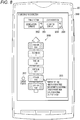
- Fig. 8 is a diagram illustrating an example of the presentation of the degree of comfort for each located car.
- the degree of comfort for each located car is presented by the presentation unit 350. For example, by presenting the degree of comfort "0.4" in the frame of the first car, the located car and the degree of comfort are presented in association with each other. Furthermore, "?” is presented in the frame of the second car for which the degree of comfort has not been calculated.
- a car having a higher degree of comfort is presented in a brighter color. In this manner, the visibility is improved by presenting variations of the degrees of comfort stepwise by color.
- the presentation unit 350 presents a car 357 expected to be boarded by the user U0 as the current position of the user U0.
- the output control unit 114 can specify the car expected to be boarded by the user U0 on the basis of the expected boarding position of the user U0 ( Fig. 5 ) and the stop position of each car ( Fig. 6 ).
- the car expected to be boarded by the user U0 is specified as "fifth car".
- the presentation unit 350 presents the degree of comfort 355 for each parameter.
- the output control unit 114 may control such that the degree of comfort 355 for each parameter is output to the presentation apparatus 30.
- the degree of comfort for each parameter may be indicated by which stage the degree of comfort belongs to, or may be indicated by a numerical value. Note that the degree of comfort for each parameter can be calculated on the basis of, for example, the multiplication of the difference value in (mathematical formula 2) by the parameter.
- a comfort degree presentation button 351 for the directly previous train a comfort degree presentation button 352 for the directly next train, a comfort degree presentation button 353 for the directly previous station, a comfort degree presentation button 354 for the directly next station are presented.
- the user U0 can switch a train for which the degree of comfort is presented, or switch a station for which the degree of comfort is presented.
- two pieces of the position information have a predetermined relationship between the user U0 and the user U4 (the car expected to be boarded by the user U0 and the located car of the user U4 are both the same "fifth car”).
- the output control unit 114 control such that predetermined notification information is output to the presentation apparatus 30.
- the user U0 can notice the presence of a car having a higher degree of comfort.
- the notification information may be presented by voice or may be presented visually.
- the output control unit 114 may control the threshold value according to a situation in which the user U0 is placed.
- the situation in which the user U0 is placed may be the state of the user U0 or may be the schedule of the user U0.
- the output control unit 114 updates the threshold value in a case where the behavior result of the user U0 satisfies a predetermined condition. For example, in a case where it is detected that the user U0 has moved to the located car "third car" of another user (for example, the user U2) (for example, despite accepting no presentation of the notification information), the output control unit 114 may update the threshold value (for example, the notification information may be ensured to be more promptly notified by reducing the threshold value).
- the output control unit 114 may set the threshold value to a predetermined value.
- the predetermined value is not limited, for example, the predetermined value may be designated as zero in order to ensure that the notification information is more promptly notified.
- the first situation may be a state in which the user U0 is located at the platform of the station ST.
- the output control unit 114 may control the threshold value on the basis of a cost corresponding to the type of the train expected to be boarded by the user U0. For example, the output control unit 114 may raise the threshold value for a higher cost (the notification information may be ensured to be notified less promptly).
- the cost is not particularly limited.
- the cost may include various fees for getting on an applicable type of train (for example, a boarding fee , a fee for a reserved seat, and the like).
- the output control unit 114 may control the threshold value on the basis of the tightness of schedule of the user U0. For example, the output control unit 114 may raise the threshold value for a tighter schedule (the notification information may be ensured to be notified less promptly).
- the first situation may be a state in which the user U0 is riding on the train.
- the first situation may be a state in which a person located in the vicinity of the user U0 is a predetermined person (for example, a child or the like).
- a predetermined person for example, a child or the like.
- whether or not a child is located in the vicinity of the user U0 may be determined on the basis of a known technology.
- a known technology there is a technology utilizing a stray sensor using Bluetooth (registered trademark).
- the output control unit 114 may control the threshold value on the basis of the remaining boarding time to the destination of the user U0. For example, the output control unit 114 may raise the threshold value for a shorter remaining boarding time (the notification information may be ensured to be notified less promptly). The remaining boarding time may be calculated in any way. As an example, the output control unit 114 acquires the search history of a transfer guide service and works out whether or not the search result of the current day or the previous day includes a path on which the user U0 is currently moving.
- the output control unit 114 can calculate, as the remaining boarding time to the train getting-off station, an average value between a time required from the station directly before the current position to the train getting-off station and a time required from the next station to the train getting-off station.
- the output control unit 114 may determine the train getting-off station from the commuting path in a life log, instead of the search history of the transfer guide service.
- the output control unit 114 may control the threshold value on the basis of the product purchase history of the user U0. Alternatively, the output control unit 114 may control the threshold value on the basis of a person located in the vicinity of the user U0.
- the output control unit 114 may control such that the notification information is not output to the presentation apparatus 30.
- the second situation may be a state in which the tightness of schedule of the user U0 exceeds predetermined tightness, or a state in which a predetermined period has not elapsed since the user U0 purchased a predetermined product (this is because, for example, in a case where a state in which a predetermined period has not elapsed since the purchase of a book is detected on the basis of the product buying history, there is a possibility that the user U0 wants to read the book without moving), or a state in which a cost corresponding to the type of a train expected to be boarded by the user U0 is higher than a predetermined cost.
- FIG. 9 is a flowchart illustrating an example of an action of the information processing system 1 according to a case where the user U0 is located at a platform of a station. Note that the flowchart illustrated in Fig. 9 only illustrates an example of an action in a case where the user U0 is located at a platform of a station. Accordingly, the action in a case where the user U0 is located at a platform of a station is not limited to the action example of the flowchart illustrated in Fig. 9 .
- the comfort degree calculation unit 113 specifies a sensor group closest to the position of the user U0, from among sensor groups near the user U0 on the train path (S12). Then, the comfort degree calculation unit 113 specifies the located car of each sensor on the basis of the located position of the sensor group at the immediately previous stop station (S13). Furthermore, the comfort degree calculation unit 113 calculates the degree of comfort for each car (S14).
- the output control unit 114 In a case where there is a car having a higher degree of comfort than the car expected to be boarded by the user U0 ("Yes" in S15), the output control unit 114 notifies the user U0 of the degree of comfort of each car together with the more comfortable car (S16). On the other hand, in a case where there is no car having a higher degree of comfort than the car expected to be boarded by the user U0 ("No" in S15), the output control unit 114 notifies the user U0 of the degree of comfort of each car together with the fact that there is not a more comfortable car (S17). Then, a similar process is executed by the server 10 for the directly next train (S18).
- Fig. 10 is a diagram illustrating an example of presentation in a case where a train is selected.
- the example illustrated in Fig. 10 assumes a case where the comfort degree presentation button 352 for the directly next train is selected by the user U0 in the example illustrated in Fig. 8 .
- the degree of presentation presented by the presentation unit 350 is updated from the example illustrated in Fig. 8 .
- the user U0 can also refer to the degree of comfort of the directly next train.
- the comfort degree calculation unit 113 can also estimate the future degree of comfort on the basis of the accumulated degrees of comfort for each type and each car of the train.
- Fig. 11 is a diagram illustrating an example of the calculation of an estimated degree of comfort. As illustrated in Fig. 11 , the comfort degree calculation unit 113 can also estimate, as the future degree of comfort, the representative value (for example, the average value, the mode value, the middle value, or the like) of the degrees of comfort accumulated for each type and each car of the train.
- Fig. 12 is a diagram illustrating an example of presentation in a case where a station is selected.
- the example illustrated in Fig. 12 assumes a case where the comfort degree presentation button 354 for the directly next station is selected by the user U0 in the example illustrated in Fig. 8 .
- the degree of presentation presented by the presentation unit 350 is updated from the example illustrated in Fig. 8 .
- the user U0 can also refer to the estimated value of the degree of comfort of the same train at the directly next station.
- FIG. 13 is a diagram for explaining an example in which a user riding on a train is notified of movement to a more comfortable car.
- a case where a train made up of a plurality of cars is traveling toward the station ST is assumed, as in the example illustrated in Fig. 1 .
- the user U0 is riding in the fourth car from the front of the train.
- Other assumptions are similar to the example illustrated in Fig. 1 .
- Fig. 14 is a diagram for explaining a technique of calculating the type of a train on which the users U0 to U5 are riding and an immediately previous stop station of the train.
- the comfort degree calculation unit 113 can detect whether or not the user U0 is moving on the train path, on the basis of the position information on the user U0 and the station position. Then, on the basis of the movement history, the comfort degree calculation unit 113 can specify a user group moving in the same manner as the user U0. In the example illustrated in Fig. 14 , the comfort degree calculation unit 113 specifies the users U1 to U5 as such a user group.
- Fig. 15 is a diagram for explaining a technique of specifying a located car of each user at a stop station.
- the comfort degree calculation unit 113 can specify the located car of each user at the stop station on the basis of the located position of each user at the immediately previous stop station and the stop position of each car at the station. The calculation of the degree of comfort and the like can be carried out similarly to a case where the user is located at the platform of the station.
- Fig. 16 is a diagram illustrating an example of the presentation of the degree of comfort for each located car.
- the current position of the user U0 and the degree of comfort for each located car is presented by the presentation unit 350.
- the presentation unit 350 For example, by presenting the degree of comfort "0.4" in the frame of the first car, the located car and the degree of comfort are presented in association with each other.
- "?" is presented in the frame of the second car for which the degree of comfort has not been calculated.
- a car having a higher degree of comfort is presented in a brighter color. In this manner, the visibility is improved by presenting variations of the degrees of comfort stepwise by color.
- the presentation unit 350 presents a located car 357 of the user U0 as the current position of the user U0.
- a comfort degree presentation button 353 for the directly previous section and a comfort degree presentation button 354 for the directly next section are presented. By selecting these buttons, the user U0 can switch a section for which the degree of comfort is presented.
- two pieces of the position information have a predetermined relationship between the user U0 and the user U4 (the located car of the user U0 and the located car of the user U4 are both the same "fifth car”).
- the output control unit 114 control such that predetermined notification information is output to the presentation apparatus 30.
- the user U0 can notice the presence of a car having a higher degree of comfort.
- the output control unit 114 may control the threshold value according to a situation in which the user U0 is placed. For example, the output control unit 114 may control the threshold value on the basis of the posture of the user U0 in the train.
- the output control unit 114 may control such that the notification information is not output to the presentation apparatus 30.
- the second situation may be a state in which the estimated reaching time at the destination of the user U0 is later than the time according to the event start time, or a state in which the user U0 has a predetermined posture (for example, a posture of sitting down) in the train, or a state in which the remaining boarding time to the destination of the user U0 is shorter than a predetermined time.
- a part or all of weights corresponding to the plurality of respective sensors may be updated dynamically. For example, in a case where the behavior result of the user U0 satisfies a predetermined condition, the output control unit 114 may update a part or all of the weights corresponding to the plurality of respective sensors.
- the output control unit 114 may update a weight corresponding to a parameter that has changed in a direction in which the degree of comfort increases in correspondence to a change from the degree of comfort of the car expected to be boarded by the user U0 to the degree of comfort of the located car "third car” of the another user (for example, the user U2).
- the movement destination car of the user U0 in the train may be detected in any way.
- the movement destination car may be detected on the basis of the degree of congestion of the train and the walking speed of the user U0.
- FIG. 17 is a flowchart illustrating an example of an action of the information processing system 1 according to a case where the user U0 is riding on a train. Note that the flowchart illustrated in Fig. 17 only illustrates an example of an action in a case where the user U0 is riding on a train. Accordingly, the action in a case where the user U0 is riding on a train is not limited to the action example of the flowchart illustrated in Fig. 17 .
- the comfort degree calculation unit 113 specifies a sensor group moving in the same manner as the user U0 on the train path (S22). S13 and S14 are carried out similarly to a case where the user U0 is located at a platform of a station.
- the output control unit 114 In a case where there is a car having a higher degree of comfort than the located car of the user U0 ("Yes" in S25), the output control unit 114 notifies the user U0 of the degree of comfort of each car together with the more comfortable car (S16). On the other hand, in a case where there is no car having a higher degree of comfort than the located car of the user U0 ("No" in S15), the output control unit 114 notifies the user U0 of the degree of comfort of each car together with the fact that there is not a more comfortable car (S17). Then, a similar process is executed by the server 10 for the directly next train (S18).
- Fig. 18 is a block diagram illustrating a hardware configuration example of the information processing apparatus 10 according to the embodiment of the present disclosure.
- the information processing apparatus 10 includes a central processing unit (CPU) 901, a read only memory (ROM) 903, and a random access memory (RAM) 905.
- the control unit 110 can be implemented by the CPU 901, the ROM 903, and the RAM 905.
- the information processing apparatus 10 may include a host bus 907, a bridge 909, an external bus 911, an interface 913, an input apparatus 915, an output apparatus 917, a storage apparatus 919, a drive 921, a connection port 923, and a communication apparatus 925.
- the information processing apparatus 10 may include an imaging apparatus 933 and a sensor 935 as needed.
- the information processing apparatus 10 may have a processing circuit called a digital signal processor (DSP) or an application specific integrated circuit (ASIC).
- DSP digital signal processor
- ASIC application specific integrated circuit
- the CPU 901 functions as an arithmetic processing unit and a control apparatus and controls the overall action in the information processing apparatus 10 or a part of the action in accordance with various programs recorded in the ROM 903, the RAM 905, the storage apparatus 919, or a removable recording medium 927.
- the ROM 903 stores programs, computation parameters, and the like used by the CPU 901.
- the RAM 905 temporarily stores programs used in the execution of the CPU 901, parameters and the like that appropriately change during the execution.
- the CPU 901, the ROM 903, and the RAM 905 are mutually connected by the host bus 907 configured from an internal bus such as a CPU bus.
- the host bus 907 is connected to the external bus 911 such as a peripheral component interconnect/interface (PCI) bus via the bridge 909.
- PCI peripheral component interconnect/interface
- the input apparatus 915 is, for example, an apparatus operated by the user, such as a button.
- the input apparatus 915 may include a mouse, a keyboard, a touch panel, a switch, a lever, and the like.
- the input apparatus 915 may include a microphone that detects the voice of the user.
- the input apparatus 915 may be a remote controlling apparatus utilizing infrared rays or other electrical waves, or may be externally connected equipment 929 such as a mobile phone compatible with the operation of the information processing apparatus 10.
- the input apparatus 915 includes an input control circuit that generates an input signal on the basis of information input by the user and outputs the generated input signal to the CPU 901.
- the user operates this input apparatus 915 to input various types of data to the information processing apparatus 10 or instruct the information processing apparatus 10 on processing actions.
- the imaging apparatus 933 which will be described later, can also function as an input apparatus by imaging the motion of the hand of the user, the finger of the user, and the like. At this time, the pointing position may be found out according to the motion of the hand or the orientation of the finger.
- the output apparatus 917 is configured from an apparatus capable of visually or audibly notify the user of the acquired information.
- the output apparatus 917 may be, for example, a viewing apparatus such as a liquid crystal display (LCD) or an organic electro-luminescence (EL) display, a sound output apparatus such as a speaker or a headphone, or the like.
- the output apparatus 917 may include a plasma display panel (PDP), a projector, a hologram, a printer apparatus, and the like.
- PDP plasma display panel
- the output apparatus 917 outputs a result obtained by the process by the information processing apparatus 10 as text or a video such as an image or outputs the result as a sound such as voice or acoustics.
- the output apparatus 917 may include a light or the like for brightening the surroundings.
- the storage apparatus 919 is an apparatus for keeping data configured as an example of the storage unit of the information processing apparatus 10.
- the storage apparatus 919 is configured from, for example, a magnetic storing device such as a hard disk drive (HDD), a semiconductor storing device, an optical storing device, a magneto-optical storing device, or the like.
- This storage apparatus 919 keeps programs and various types of data executed by the CPU 901, various types of data acquired from the outside, and the like.
- the drive 921 is a reader/writer for the removable recording medium 927 such as a magnetic disk, an optical disc, a magneto-optical disk, or a semiconductor memory, and is incorporated in or externally attached to the information processing apparatus 10.
- the drive 921 reads information recorded on the mounted removable recording medium 927 and outputs the read information to the RAM 905. Furthermore, the drive 921 writes a record in the mounted removable recording medium 927.
- the connection port 923 is a port for connecting equipment straight to the information processing apparatus 10.
- the connection port 923 can be, for example, a universal serial bus (USB) port, an Institute of Electrical and Electronic Engineers (IEEE) 1394 port, a small computer system interface (SCSI) port, or the like.
- the connection port 923 may be a recommended standard (RS)-232C port, an optical audio terminal, a high-definition multimedia interface (HDMI) (registered trademark) port, or the like.
- RS recommended standard
- HDMI high-definition multimedia interface
- the communication apparatus 925 is, for example, a communication interface configured from a communication device or the like for connecting to the network 931.
- the communication apparatus 925 can be, for example, a communication card for a wired or wireless local area network (LAN), Bluetooth (registered trademark), wireless USB (WUSB), or the like.
- the communication apparatus 925 may be a router for optical communication, a router for asymmetric digital subscriber line (ADSL), a modem for various communications, or the like.
- the communication apparatus 925 transmits and receives signals and the like to and from the Internet and other communication equipment, using a predetermined protocol such as transmission control protocol/Internet protocol (TCP/IP).
- TCP/IP transmission control protocol/Internet protocol
- the network 931 connected to the communication apparatus 925 is a network connected in a wired or wireless manner and is, for example, the Internet, a home LAN, infrared communication, radio wave communication, satellite communication, or the like.
- the communication unit 140 described above can be implemented by the communication apparatus 925.
- the imaging apparatus 933 is an apparatus that images a real space using various members including an imaging element such as a charge coupled device (CCD) or complementary metal oxide semiconductor (CMOS) and a lens or the like for controlling imaging of a subject image on the imaging element, and generates a captured image.
- the imaging apparatus 933 may capture a still image or may capture a moving image.
- the sensor 935 serves as, for example, various sensors such as a distance measuring sensor, an acceleration sensor, a gyro sensor, a geomagnetic sensor, a vibration sensor, an optical sensor, and a sound sensor.
- the sensor 935 acquires information regarding the environment around the information processing apparatus 10, including information regarding the state of the entire information processing apparatus 10, such as the attitude of the casing of the information processing apparatus 10, the brightness and noise around the information processing apparatus 10, and the like.
- the sensor 935 may include a global positioning system (GPS) sensor that receives a GPS signal and measures the latitude, longitude, and altitude of the apparatus.
- GPS global positioning system
- an information processing apparatus including: a comfort degree calculation unit that calculates a degree of comfort of a particular user on the basis of sensor data of another user; and an output control unit that controls such that information regarding the degree of comfort is output to a terminal of the particular user.
- a comfort degree calculation unit that calculates a degree of comfort of a particular user on the basis of sensor data of another user
- an output control unit that controls such that information regarding the degree of comfort is output to a terminal of the particular user.
Landscapes
- Engineering & Computer Science (AREA)
- Mechanical Engineering (AREA)
- General Physics & Mathematics (AREA)
- Health & Medical Sciences (AREA)
- Physics & Mathematics (AREA)
- General Health & Medical Sciences (AREA)
- Business, Economics & Management (AREA)
- Computing Systems (AREA)
- Computer Networks & Wireless Communication (AREA)
- Signal Processing (AREA)
- Medical Informatics (AREA)
- Primary Health Care (AREA)
- Human Resources & Organizations (AREA)
- Marketing (AREA)
- Economics (AREA)
- Strategic Management (AREA)
- Tourism & Hospitality (AREA)
- General Business, Economics & Management (AREA)
- Theoretical Computer Science (AREA)
- Train Traffic Observation, Control, And Security (AREA)
- Management, Administration, Business Operations System, And Electronic Commerce (AREA)
Applications Claiming Priority (2)
| Application Number | Priority Date | Filing Date | Title |
|---|---|---|---|
| JP2017041304 | 2017-03-06 | ||
| PCT/JP2017/045348 WO2018163560A1 (fr) | 2017-03-06 | 2017-12-18 | Dispositif de traitement d'informations, procédé de traitement d'informations et programme |
Publications (2)
| Publication Number | Publication Date |
|---|---|
| EP3594893A4 EP3594893A4 (fr) | 2020-01-15 |
| EP3594893A1 true EP3594893A1 (fr) | 2020-01-15 |
Family
ID=63448466
Family Applications (1)
| Application Number | Title | Priority Date | Filing Date |
|---|---|---|---|
| EP17899352.3A Withdrawn EP3594893A1 (fr) | 2017-03-06 | 2017-12-18 | Dispositif de traitement d'informations, procédé de traitement d'informations et programme |
Country Status (4)
| Country | Link |
|---|---|
| US (1) | US11173931B2 (fr) |
| EP (1) | EP3594893A1 (fr) |
| JP (1) | JP6992799B2 (fr) |
| WO (1) | WO2018163560A1 (fr) |
Families Citing this family (3)
| Publication number | Priority date | Publication date | Assignee | Title |
|---|---|---|---|---|
| JP2020115274A (ja) * | 2019-01-17 | 2020-07-30 | 株式会社アルファコード | 仮想空間画像表示制御装置および仮想空間画像表示制御用プログラム |
| CN113658029A (zh) * | 2021-08-13 | 2021-11-16 | 北京北大千方科技有限公司 | 用于智慧出行研判的公交车舒适度查询方法、系统及设备 |
| JP2023132524A (ja) * | 2022-03-11 | 2023-09-22 | 株式会社フジタ | 情報提供システム |
Family Cites Families (17)
| Publication number | Priority date | Publication date | Assignee | Title |
|---|---|---|---|---|
| JPH03156239A (ja) * | 1989-11-10 | 1991-07-04 | Hitachi Ltd | 空気調和機 |
| JPH07253477A (ja) * | 1994-03-15 | 1995-10-03 | Sanyo Electric Works Ltd | 快適度測定装置 |
| USRE39881E1 (en) * | 1996-02-15 | 2007-10-16 | Leapfrog Enterprises, Inc. | Surface position location system and method |
| US5877458A (en) * | 1996-02-15 | 1999-03-02 | Kke/Explore Acquisition Corp. | Surface position location system and method |
| US7460899B2 (en) * | 2003-04-23 | 2008-12-02 | Quiescent, Inc. | Apparatus and method for monitoring heart rate variability |
| US20110296622A1 (en) * | 2010-06-03 | 2011-12-08 | Han-Chung Hsu | Active Supporting Device for Health Bed and Method thereof |
| US8954201B2 (en) * | 2011-06-03 | 2015-02-10 | Energyhub, Inc. | Realization of energy savings potential through feedback |
| JP2013104632A (ja) * | 2011-11-15 | 2013-05-30 | Stella Green Corp | 快適性分布評価方法、快適性分布評価システム、空調制御システム及びコンピュータプログラム |
| JP6002599B2 (ja) | 2013-02-22 | 2016-10-05 | 日本電信電話株式会社 | センサデータ統合装置、センサデータ統合方法及びプログラム |
| GB201313444D0 (en) * | 2013-07-29 | 2013-09-11 | Ambi Labs Ltd | Energy efficient indoor climate controller |
| JP6183047B2 (ja) | 2013-08-12 | 2017-08-23 | ソニー株式会社 | 情報処理装置、情報処理方法およびプログラム |
| JP2015094971A (ja) | 2013-11-08 | 2015-05-18 | 富士通株式会社 | 情報提供方法、情報提供装置、及び情報提供プログラム |
| CN106102565A (zh) * | 2014-05-23 | 2016-11-09 | 三星电子株式会社 | 具有模块化传感器平台的可调节可穿戴系统 |
| JP6502066B2 (ja) | 2014-11-12 | 2019-04-17 | 株式会社ナビタイムジャパン | 情報処理システム、情報処理プログラム、情報処理装置、および情報処理方法 |
| CN104598021A (zh) * | 2014-12-16 | 2015-05-06 | 天津三星电子有限公司 | 显示设备及显示方法 |
| JP6503233B2 (ja) | 2015-05-29 | 2019-04-17 | 株式会社ナビタイムジャパン | 情報処理システム、情報処理プログラム、情報処理装置、情報処理方法、出力データ、および記憶媒体 |
| CN206448556U (zh) * | 2016-12-13 | 2017-08-29 | 王庆和 | 一种自助式休息舱 |
-
2017
- 2017-12-18 JP JP2019504336A patent/JP6992799B2/ja active Active
- 2017-12-18 WO PCT/JP2017/045348 patent/WO2018163560A1/fr not_active Ceased
- 2017-12-18 US US16/485,891 patent/US11173931B2/en active Active
- 2017-12-18 EP EP17899352.3A patent/EP3594893A1/fr not_active Withdrawn
Also Published As
| Publication number | Publication date |
|---|---|
| EP3594893A4 (fr) | 2020-01-15 |
| JP6992799B2 (ja) | 2022-01-13 |
| US20200017132A1 (en) | 2020-01-16 |
| WO2018163560A1 (fr) | 2018-09-13 |
| JPWO2018163560A1 (ja) | 2020-01-16 |
| US11173931B2 (en) | 2021-11-16 |
Similar Documents
| Publication | Publication Date | Title |
|---|---|---|
| US20190383620A1 (en) | Information processing apparatus, information processing method, and program | |
| US10731992B2 (en) | Information processing device, information processing method, and program | |
| KR102525029B1 (ko) | 사용자에게 콘텐트를 제공하기 위한 장치 및 방법 | |
| JP6311478B2 (ja) | 情報処理装置、情報処理方法およびプログラム | |
| EP3522566B1 (fr) | Dispositif de traitement d'informations et procédé de traitement d'informations | |
| US20240331377A1 (en) | Information processing apparatus, information processing method, and program | |
| JP7060014B2 (ja) | 情報処理装置、情報処理方法及びプログラム | |
| WO2019049491A1 (fr) | Dispositif de traitement d'informations et procédé de traitement d'informations | |
| WO2016098457A1 (fr) | Dispositif de traitement d'informations, procédé de traitement d'informations, et programme | |
| EP3594893A1 (fr) | Dispositif de traitement d'informations, procédé de traitement d'informations et programme | |
| US20200018926A1 (en) | Information processing apparatus, information processing method, and program | |
| JP2019028767A (ja) | 表示制御装置、表示制御方法及び表示制御プログラム | |
| US20200125398A1 (en) | Information processing apparatus, method for processing information, and program | |
| WO2015194270A1 (fr) | Dispositif de traitement d'informations, procédé de traitement d'informations et programme | |
| JP2019075126A (ja) | 情報処理装置及びプログラム | |
| JP2019074649A (ja) | 情報処理装置及びプログラム | |
| KR101886836B1 (ko) | 스마트 페이지 내에서 맞춤 정보를 제공하는 방법 및 장치 | |
| WO2015194269A1 (fr) | Dispositif de traitement d'informations, procédé de traitement d'informations et programme | |
| JP2021182172A (ja) | 情報処理装置、情報処理方法およびプログラム | |
| US20200116513A1 (en) | Information processing apparatus, information processing method, and information processing system |
Legal Events
| Date | Code | Title | Description |
|---|---|---|---|
| PUAI | Public reference made under article 153(3) epc to a published international application that has entered the european phase |
Free format text: ORIGINAL CODE: 0009012 |
|
| 17P | Request for examination filed |
Effective date: 20190924 |
|
| A4 | Supplementary search report drawn up and despatched |
Effective date: 20191126 |
|
| AK | Designated contracting states |
Kind code of ref document: A1 Designated state(s): AL AT BE BG CH CY CZ DE DK EE ES FI FR GB GR HR HU IE IS IT LI LT LU LV MC MK MT NL NO PL PT RO RS SE SI SK SM TR |
|
| AX | Request for extension of the european patent |
Extension state: BA ME |
|
| DAV | Request for validation of the european patent (deleted) | ||
| DAX | Request for extension of the european patent (deleted) | ||
| STAA | Information on the status of an ep patent application or granted ep patent |
Free format text: STATUS: THE APPLICATION IS DEEMED TO BE WITHDRAWN |
|
| 18D | Application deemed to be withdrawn |
Effective date: 20200624 |