EP3595346A1 - Procédé de transmission de données, dispositif de réseau, et terminal - Google Patents
Procédé de transmission de données, dispositif de réseau, et terminal Download PDFInfo
- Publication number
- EP3595346A1 EP3595346A1 EP18777036.7A EP18777036A EP3595346A1 EP 3595346 A1 EP3595346 A1 EP 3595346A1 EP 18777036 A EP18777036 A EP 18777036A EP 3595346 A1 EP3595346 A1 EP 3595346A1
- Authority
- EP
- European Patent Office
- Prior art keywords
- time
- frequency resource
- resource block
- terminal
- network device
- Prior art date
- Legal status (The legal status is an assumption and is not a legal conclusion. Google has not performed a legal analysis and makes no representation as to the accuracy of the status listed.)
- Granted
Links
Images




Classifications
-
- H—ELECTRICITY
- H04—ELECTRIC COMMUNICATION TECHNIQUE
- H04W—WIRELESS COMMUNICATION NETWORKS
- H04W72/00—Local resource management
- H04W72/04—Wireless resource allocation
- H04W72/044—Wireless resource allocation based on the type of the allocated resource
-
- H—ELECTRICITY
- H04—ELECTRIC COMMUNICATION TECHNIQUE
- H04W—WIRELESS COMMUNICATION NETWORKS
- H04W72/00—Local resource management
- H04W72/20—Control channels or signalling for resource management
- H04W72/21—Control channels or signalling for resource management in the uplink direction of a wireless link, i.e. towards the network
-
- H—ELECTRICITY
- H04—ELECTRIC COMMUNICATION TECHNIQUE
- H04L—TRANSMISSION OF DIGITAL INFORMATION, e.g. TELEGRAPHIC COMMUNICATION
- H04L1/00—Arrangements for detecting or preventing errors in the information received
- H04L1/0001—Systems modifying transmission characteristics according to link quality, e.g. power backoff
- H04L1/0036—Systems modifying transmission characteristics according to link quality, e.g. power backoff arrangements specific to the receiver
- H04L1/0038—Blind format detection
-
- H—ELECTRICITY
- H04—ELECTRIC COMMUNICATION TECHNIQUE
- H04L—TRANSMISSION OF DIGITAL INFORMATION, e.g. TELEGRAPHIC COMMUNICATION
- H04L1/00—Arrangements for detecting or preventing errors in the information received
- H04L1/004—Arrangements for detecting or preventing errors in the information received by using forward error control
- H04L1/0045—Arrangements at the receiver end
- H04L1/0052—Realisations of complexity reduction techniques, e.g. pipelining or use of look-up tables
-
- H—ELECTRICITY
- H04—ELECTRIC COMMUNICATION TECHNIQUE
- H04L—TRANSMISSION OF DIGITAL INFORMATION, e.g. TELEGRAPHIC COMMUNICATION
- H04L5/00—Arrangements affording multiple use of the transmission path
- H04L5/0001—Arrangements for dividing the transmission path
- H04L5/0003—Two-dimensional division
- H04L5/0005—Time-frequency
-
- H—ELECTRICITY
- H04—ELECTRIC COMMUNICATION TECHNIQUE
- H04L—TRANSMISSION OF DIGITAL INFORMATION, e.g. TELEGRAPHIC COMMUNICATION
- H04L5/00—Arrangements affording multiple use of the transmission path
- H04L5/003—Arrangements for allocating sub-channels of the transmission path
- H04L5/0044—Allocation of payload; Allocation of data channels, e.g. PDSCH or PUSCH
-
- H—ELECTRICITY
- H04—ELECTRIC COMMUNICATION TECHNIQUE
- H04L—TRANSMISSION OF DIGITAL INFORMATION, e.g. TELEGRAPHIC COMMUNICATION
- H04L5/00—Arrangements affording multiple use of the transmission path
- H04L5/003—Arrangements for allocating sub-channels of the transmission path
- H04L5/0048—Allocation of pilot signals, i.e. of signals known to the receiver
-
- H—ELECTRICITY
- H04—ELECTRIC COMMUNICATION TECHNIQUE
- H04W—WIRELESS COMMUNICATION NETWORKS
- H04W28/00—Network traffic management; Network resource management
- H04W28/02—Traffic management, e.g. flow control or congestion control
- H04W28/0231—Traffic management, e.g. flow control or congestion control based on communication conditions
-
- H—ELECTRICITY
- H04—ELECTRIC COMMUNICATION TECHNIQUE
- H04W—WIRELESS COMMUNICATION NETWORKS
- H04W28/00—Network traffic management; Network resource management
- H04W28/16—Central resource management; Negotiation of resources or communication parameters, e.g. negotiating bandwidth or QoS [Quality of Service]
-
- H—ELECTRICITY
- H04—ELECTRIC COMMUNICATION TECHNIQUE
- H04W—WIRELESS COMMUNICATION NETWORKS
- H04W4/00—Services specially adapted for wireless communication networks; Facilities therefor
- H04W4/70—Services for machine-to-machine communication [M2M] or machine type communication [MTC]
-
- H—ELECTRICITY
- H04—ELECTRIC COMMUNICATION TECHNIQUE
- H04W—WIRELESS COMMUNICATION NETWORKS
- H04W72/00—Local resource management
- H04W72/20—Control channels or signalling for resource management
- H04W72/23—Control channels or signalling for resource management in the downlink direction of a wireless link, i.e. towards a terminal
-
- H—ELECTRICITY
- H04—ELECTRIC COMMUNICATION TECHNIQUE
- H04W—WIRELESS COMMUNICATION NETWORKS
- H04W72/00—Local resource management
- H04W72/50—Allocation or scheduling criteria for wireless resources
- H04W72/54—Allocation or scheduling criteria for wireless resources based on quality criteria
-
- H—ELECTRICITY
- H04—ELECTRIC COMMUNICATION TECHNIQUE
- H04L—TRANSMISSION OF DIGITAL INFORMATION, e.g. TELEGRAPHIC COMMUNICATION
- H04L1/00—Arrangements for detecting or preventing errors in the information received
- H04L1/08—Arrangements for detecting or preventing errors in the information received by repeating transmission, e.g. Verdan system
-
- H—ELECTRICITY
- H04—ELECTRIC COMMUNICATION TECHNIQUE
- H04W—WIRELESS COMMUNICATION NETWORKS
- H04W4/00—Services specially adapted for wireless communication networks; Facilities therefor
- H04W4/02—Services making use of location information
-
- H—ELECTRICITY
- H04—ELECTRIC COMMUNICATION TECHNIQUE
- H04W—WIRELESS COMMUNICATION NETWORKS
- H04W72/00—Local resource management
- H04W72/02—Selection of wireless resources by user or terminal
-
- Y—GENERAL TAGGING OF NEW TECHNOLOGICAL DEVELOPMENTS; GENERAL TAGGING OF CROSS-SECTIONAL TECHNOLOGIES SPANNING OVER SEVERAL SECTIONS OF THE IPC; TECHNICAL SUBJECTS COVERED BY FORMER USPC CROSS-REFERENCE ART COLLECTIONS [XRACs] AND DIGESTS
- Y02—TECHNOLOGIES OR APPLICATIONS FOR MITIGATION OR ADAPTATION AGAINST CLIMATE CHANGE
- Y02D—CLIMATE CHANGE MITIGATION TECHNOLOGIES IN INFORMATION AND COMMUNICATION TECHNOLOGIES [ICT], I.E. INFORMATION AND COMMUNICATION TECHNOLOGIES AIMING AT THE REDUCTION OF THEIR OWN ENERGY USE
- Y02D30/00—Reducing energy consumption in communication networks
- Y02D30/70—Reducing energy consumption in communication networks in wireless communication networks
Definitions
- This application relates to the field of communications technologies, and in particular, to a data transmission method, a network device, and a terminal in the field of wireless communications.
- a current communications system mainly supports voice communication and data communication.
- a conventional base station supports a limited quantity of connections.
- a next generation mobile communications system needs to support not only the conventional voice communication and data communication, but also machine-to-machine (Machine to Machine, M2M for short) communication, or referred to as massive machine type communications (Massive Machine Type Communication, mMTC for short). It is predicated that a quantity of mMTC devices connected to a network is to reach 50 billion to 100 billion by year 2020, and far exceeds a current quantity of connections.
- One service is a latency-insensitive service that needs reliable transmission; and the other service is a service that needs low-latency and high-reliability transmission.
- the latency-insensitive service that needs reliable transmission is relatively easy to process.
- transmission is unreliable, retransmission may be caused, and consequently, a transmission latency is excessively large. Therefore, a requirement cannot be met.
- an uplink grant-free (Grant Free) transmission solution is applied to this type of services.
- a grant-free transmission system there are a large quantity of terminals, but there are a very small quantity of terminals that access a network.
- a terminal may randomly select a grant-free transmission resource to send data.
- a base station In a grant-free transmission mechanism, a base station needs to perform, on the grant-free transmission resource, blind detection on uplink data sent by the terminal. Demodulation complexity is very high. How to reduce demodulation complexity is a technical problem that urgently needs to be resolved.
- Embodiments of this application provide a data transmission method, a network device, and a terminal.
- This application provides a data transmission method, where the method includes:
- an uplink transmission time-frequency resource is divided into a plurality of time-frequency resource blocks, and corresponding configuration information is configured for each time-frequency resource block.
- a network device divides the uplink transmission time-frequency resource into the plurality of time-frequency resource blocks, and stores the uplink transmission time-frequency resource divided into the plurality of time-frequency resource blocks.
- a device development or maintenance person configures, for the network device, a table or parameter information indicating division of the uplink transmission time-frequency resource into the plurality of time-frequency resource blocks.
- the uplink transmission time-frequency resource is divided into the plurality of time-frequency resource blocks in the following two manners: In one manner, the uplink transmission time-frequency resource is associated with a terminal group, the uplink transmission time-frequency resource is first divided based on a terminal group, and then an uplink transmission time-frequency resource specific to each terminal group is further divided into different time-frequency resource blocks. In the other manner, terminal groups are not distinguished, the uplink transmission time-frequency resource is directly divided into different time-frequency resource blocks.
- the configuration information is associated with each time-frequency resource block. When the terminal selects a time-frequency resource block, or selects a time-frequency resource block corresponding to a terminal group to which the terminal belongs, the terminal may use an uplink transmission configuration corresponding to the time-frequency resource block.
- the uplink transmission time-frequency resource herein is a time-frequency resource that is reserved by the network device for the terminal and that is used for uplink grant-free transmission, or a contention transmission unit (Contention Transmission Unit, CTU) used for uplink grant-free transmission.
- the uplink transmission time-frequency resource can be configured within a range of a time-frequency resource used by a group of terminals to perform uplink grant-free transmission, or a time-frequency resource of an entire bandwidth.
- sizes of time-frequency resource blocks may be different, or may be the same.
- the time-frequency resource blocks are distinguished by using sub-bands in a dimension of frequency domain.
- Each of the plurality of time-frequency resource blocks occupies a same bandwidth, or at least two of the plurality of time-frequency resource blocks occupy different bandwidths.
- a quantity of subcarriers included in each sub-band may be the same or different.
- the time-frequency resource blocks are distinguished by using a subframe, a slot, or a mini-slot in a dimension of time domain.
- a quantity of symbols occupied by each of the time-frequency resource blocks in time domain is the same, or quantities of symbols occupied by at least two time-frequency resource blocks in time domain are different.
- the time-frequency resource may be flexibly divided as required.
- the terminal may flexibly select, based on a transmission requirement, a size of a time-frequency resource block suitable for current transmission.
- each time-frequency resource block is a sub-band.
- the configuration information includes identification information of a configured time-frequency resource block in the uplink transmission time-frequency resource, and the identification information is a start position or an index number of a corresponding time-frequency resource block.
- the configuration information further includes a quantity of configured time-frequency resource blocks in the uplink transmission time-frequency resource.
- the configuration information further includes an upper limit of a quantity of available time-frequency resource blocks in the uplink transmission time-frequency resource.
- the configuration information further includes lengths and end positions of time-frequency resource blocks in the uplink transmission time-frequency resource.
- the configuration information is explicitly indicated by using signaling, or implicitly indicated by using a pilot pattern, or indicated by using a pilot sequence.
- the network device After the configuration information is configured for each time-frequency resource block, the network device sends the plurality of time-frequency resource blocks and corresponding configuration information to the terminal. In a possible implementation, when the terminal needs to send an uplink signal, the network device sends configuration information to the terminal.
- the terminal receives the plurality of time-frequency resource blocks and corresponding configuration information sent by the network device to the terminal, and locally stores the plurality of time-frequency resource blocks and the corresponding configuration information for use in uplink transmission.
- the terminal selects, for uplink transmission, one or more time-frequency resource blocks from the plurality of time-frequency resource blocks.
- a time-frequency resource block parameter for performing uplink transmission by the terminal, and a parameter required for coverage enhancement are included.
- the time-frequency resource block parameter includes at least identification information of a time-frequency resource block.
- the identification information may be a start position of the resource block or may be an index number of the resource block.
- the time-frequency resource block parameter further includes a length of the time-frequency resource block or an end position of the time-frequency resource block, a granularity of the time-frequency resource block, and the like.
- the parameter required for coverage enhancement includes parameter information such as a power control parameter, a TTI bundling size indication, or a repetition size indication.
- the terminal when sending the uplink data, may further notify the network device of identification information of the time-frequency resource block selected by the terminal.
- the identification information of the time-frequency resource block may be sent together with the uplink data, or may be independently sent (in other words, the identification information of the time-frequency resource block is sent without the uplink data).
- the terminal when the configuration information of the time-frequency resource block includes a start position or an index number, the terminal sends the uplink data on a time-frequency resource block indicated by the start position or the index number of the time-frequency resource block.
- the configuration information of the time-frequency resource block further includes the start position and a length, the terminal sends, by using the start position of the time-frequency resource block as a start point, the uplink data on a time-frequency resource block corresponding to the length.
- the terminal sends the uplink data on a time-frequency resource block whose start point is the start position of the time-frequency resource block and whose end point is the end position of the time-frequency resource block.
- the terminal sends, by using the start position of the time-frequency resource block as a start point, the uplink data on a time-frequency resource block represented by a time-frequency resource width used as a granularity.
- the terminal sends, by using the start position of the time-frequency resource block as a start point, the uplink data on a time-frequency resource block corresponding to a power indicated by using the power control parameter.
- the terminal sends, by using the start position of the time-frequency resource block as a start point, the uplink data in several bundled time units that has several time intervals indicated by using the TTI bundling size; or the terminal sends, by using the start position of the time-frequency resource block as a start point, the uplink data in several repeated transmission time units indicated by using the repetition size.
- the network device can correctly demodulate, through blind detection, the uplink data received from the terminal.
- the identification information of the time-frequency resource block is indicated in the configuration information, and based on the identification information, the network device performs blind detection for a limited quantity of times within a limited range. In this case, the network device does not need to perform blind demodulation for a plurality of times to test various possibilities, thereby reducing complexity of blind detection.
- the terminal may further add, to the uplink information, the identification information of the at least one time-frequency resource block selected by the terminal, to send the uplink information to the network device.
- the terminal when the terminal sends, to the network device by using uplink control signaling, the identification of the at least one time-frequency resource block selected by the terminal, and uplink data is sent to the network device through a data channel.
- the network device determines a start position of the corresponding time-frequency resource block by detecting a sequence sent by the terminal, and detects, on the start position, that in all the three manners in which the terminal transmits the uplink data, the network device can perform correct demodulation, thereby further reducing complexity of demodulation.
- the uplink transmission time-frequency resource pre-allocated by the network device to the terminal is divided into the plurality of time-frequency resource blocks. Therefore, the terminal may select a time-frequency resource with a relatively narrow bandwidth to perform uplink transmission, thereby increasing a transmit power of the terminal. Further, the network device further configures the configuration information for each time-frequency resource block. The configuration information may carry a sub-band parameter or a coverage enhancement parameter, or both the sub-band parameter and the coverage enhancement parameter. Therefore, after selecting the time-frequency resource block used for the uplink transmission, the terminal performs the uplink transmission based on the corresponding configuration information, to further increase a transmit power. In addition, the network device may perform demodulation on a correct time-frequency resource block based on the configuration information, to improve demodulation efficiency and avoid generating a processing latency.
- an embodiment of this application provides a network device, where the network device may be a base station or a control node.
- the network device includes:
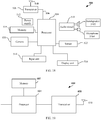
- an embodiment of this application provides a base station, where the base station has a function of implementing behavior of the base station in the foregoing method designs.
- the functions may be implemented by hardware, or may be implemented by hardware executing corresponding software.
- the hardware or the software includes at least one module corresponding to the foregoing function.
- a structure of the base station includes a processor and a transceiver, where the processor is configured to support the base station in performing corresponding functions in the foregoing method.
- the transceiver is configured to: support communication between the base station and the terminal; send the information or signaling to the terminal in the method; and receive information or an instruction sent by the base station.
- the base station may further include a memory.
- the memory is coupled to the processor, and the memory stores a program instruction and data that are necessary to the base station.
- an embodiment of this application provides a control node, where the control node may include a controller/processor, a memory, and a communications unit.
- the controller/processor may be configured to coordinate resource management and configuration among a plurality of base stations, and may be configured to perform the method steps of configuring the time-frequency resource for the terminal described in the foregoing embodiment.
- the memory may be configured to store program code and data of the control node.
- the communications unit is configured to support the control node in communicating with a base station, for example, sending information about a configured resource to the base station.
- an embodiment of this application provides a terminal, where the terminal has a function of implementing behavior of the terminal in the foregoing method designs.
- the function may be implemented by hardware.
- the terminal includes:
- the terminal may further include a memory, and the memory is configured to store information about the time-frequency resource used to transmit the uplink data.
- the time-frequency resource includes a plurality of time-frequency resource blocks.
- the memory may be integrated into the processor.
- the terminal may be alternatively implemented by hardware executing corresponding software.
- the hardware or the software includes at least one module corresponding to the foregoing function.
- the module may be software and/or hardware.
- an embodiment of this application further provides a processing apparatus, where the processing apparatus includes a processor and an interface.
- the processor is configured to obtain information about a time-frequency resource used to transmit uplink data.
- the time-frequency resource includes a plurality of time-frequency resource blocks; the information about the time-frequency resource includes configuration information corresponding to each time-frequency resource block; and the configuration information includes at least identification information of the corresponding time-frequency resource block.
- the processor is further configured to: when the uplink data needs to be sent, select at least one time-frequency resource block from the plurality of time-frequency resource blocks, and provide the at least one selected time-frequency resource block for a transceiver through the interface, so that the transceiver transmits the uplink data on the at least one selected time-frequency resource block.
- the processing apparatus may be a chip.
- the processor may be implemented by using hardware or software.
- the processor When implemented by using the hardware, the processor may be a logic circuit, an integrated circuit, or the like.
- the processor When implemented by using the software, the processor may be a general-purpose processor, and is implemented by reading software code stored in a memory.
- the memory may be integrated into the processor, or may be located outside the processor and exist independently.
- an embodiment of this application provides a communications system, where the system includes the base station and the terminal in the foregoing aspects.
- the system may further include the control node in the foregoing embodiment.
- an embodiment of this application provides computer storage medium, where the computer storage medium is configured to store computer software instruction used by the foregoing base station, and the computer software instruction includes a program used to perform the foregoing aspects.
- an embodiment of this application provides computer storage medium, where the computer storage medium is configured to store computer software instruction used by the foregoing terminal, and the computer software instruction includes a program used to perform the foregoing aspects.
- the uplink transmission time-frequency resource pre-allocated by the network device to the terminal is divided into the plurality of sub-bands. Therefore, the terminal may select a time-frequency resource with a relatively narrow bandwidth to perform uplink transmission, thereby increasing a transmit power of the terminal. Further, the network device further configures the configuration information for each sub-band. The configuration information may carry a sub-band parameter or a coverage enhancement parameter, or both the sub-band parameter and the coverage enhancement parameter. Therefore, after selecting the sub-band used for the uplink transmission, the terminal performs the uplink transmission based on the corresponding configuration information, to further increase a transmit power. In addition, the network device may perform demodulation on a correct time-frequency resource block based on the configuration information, to improve demodulation efficiency and avoid generating a processing latency.
- a base station may adjust, in real time, a time-frequency resource for performing uplink transmission by each terminal.
- a base station may adjust, in real time, a time-frequency resource for performing uplink transmission by each terminal.
- the terminal When the terminal needs to send uplink data, the terminal sends an uplink resource scheduling request to the base station.
- the base station may configure a plurality of subframes or slots (slot) for the terminal, so that the terminal performs TTI bundling.
- the base station reduces a transmission bandwidth of the terminal in frequency domain, to increase a transmit power of the terminal in a single time-frequency resource block (Resource Block, RB).
- Resource Block Resource Block
- the base station uses a combination of the foregoing two manners for the terminal.
- the terminal sends uplink data based on scheduling performed by the base station, and the base station demodulates the data at a time-frequency position specified in scheduling information.
- next generation mobile network Next Generation Mobile Network
- eMBB enhanced mobile broadband
- uRLLC ultra-reliable and low-latency communications
- mMTC massive machine type communications
- mMTC coverage meets a digital society requirement of people.
- Atypical characteristic of the scenario is massive connectivity. In other words, there is a large quantity of terminals.
- Service types are mainly a small packet service, and there is a specific requirement for a low latency.
- URLLC focuses on a service that is very sensitive to a latency, such as automatic driving or assisted driving.
- a service that is very sensitive to a latency, such as automatic driving or assisted driving.
- a system capacity is not a major concern, but there is a high requirement for a latency and reliability.
- grant-free transmission is considered as a better and more suitable uplink data transmission method than grant-based transmission.
- a transmission latency is greatly shortened because a process of sending an uplink scheduling request and waiting to receive a grant from the base station is not required, thereby meeting a latency requirement.
- a resource of transmitting data by the terminal is reserved in advance, and the reserved resource is usually specific to a plurality of terminals in some scenarios.
- the base station adjusts a reserved resource in real time based on a change of a coverage requirement of the terminal, a relatively great quantity of signaling overheads and a relatively long transmission latency are caused.
- the base station does not know, in advance, a time-frequency position at which the terminal transmits data, and needs to perform blind demodulation for a plurality of times to test various possibilities. Consequently, demodulation complexity and a processing latency are increased.
- An uplink transmission time-frequency resource configured for the terminal is divided into a plurality of time-frequency resource blocks, and therefore, the terminal may select a time-frequency resource with a relatively narrow bandwidth to perform uplink transmission, thereby increasing a transmit power of the terminal.
- the network device configures corresponding configuration information for each time-frequency resource sub-block.
- the configuration information may carry a time-frequency resource block parameter or a coverage enhancement parameter, or both two parameters.
- the terminal after selecting a time-frequency resource block for uplink transmission, the terminal performs the uplink transmission based on the corresponding configuration information, to further increase a transmit power.
- the network device may further perform demodulation on a correct time-frequency resource block based on the configuration information, to improve demodulation efficiency and avoid generating a processing latency.
- the embodiments of this application provide an uplink transmission technology.
- application of the technical solutions provided in this application is not limited only to URLLC and mMTC scenarios, and the data transmission method, the terminal, and the network device provided in this application may all apply to any other grant-free transmission scenario that does not require scheduling performed by the base station.
- the grant-free transmission in the embodiments of this application may be denoted as grant free in English, and an abbreviation is GF.
- the grant-free transmission may be also expressed in another form, for example, grantless or contention based.
- a meaning of the grant-free transmission is not limited in this specification. It may be understood that the grant-free transmission herein is not a proper noun and may have other names in actual application, but none of the names departs from the essence of this patent application.
- the grant-free transmission is usually performed for uplink data transmission, and may be understood as any one or more of the following meanings, but is not limited to the meanings.
- the grant-free transmission may be also understood as a combination of some technical features in the following plurality of meanings or another similar meaning.
- the grant-free transmission may mean that a network device pre-allocates a plurality of transmission resources and notifies a terminal of the plurality of transmission resources; when the terminal needs to transmit uplink data, the terminal selects at least one transmission resource from the plurality of transmission resources pre-allocated by the network device, and sends the uplink data by using the selected transmission resource; and the network device detects, on the at least one of the plurality of pre-allocated transmission resources, the uplink data transmitted by the terminal.
- the detection may be blind detection, detection performed based on a specific control field in the uplink data, or detection performed in another manner.
- the grant-free transmission may mean that a network device pre-allocates a plurality of transmission resources and notifies a terminal of the plurality of transmission resources, so that when the terminal needs to transmit uplink data, the terminal selects at least one transmission resource from the plurality of transmission resources pre-allocated by the network device, and sends the uplink data by using the selected transmission resource.
- the grant-free transmission may mean that information about a plurality of pre-allocated transmission resources is obtained; and when uplink data needs to be transmitted, at least one transmission resource is selected from the plurality of transmission resources, and the uplink data is sent by using the selected transmission resource.
- the information about the plurality of pre-allocated transmission resources may be obtained from a network device.
- the grant-free transmission may refer to a method for implementing uplink data transmission performed by a terminal without a requirement of dynamic scheduling performed by a network device, and the dynamic scheduling may refer to a scheduling mode in which the network device indicates, by using signaling, a transmission resource of transmitting uplink data each time by the terminal.
- implementation of the uplink data transmission performed by the terminal can be understood as follows: Two or more terminals are allowed to transmit uplink data on a same time-frequency resource.
- the transmission resource may be a transmission resource in at least one transmission time unit following a moment at which the terminal receives the signaling.
- One transmission time unit may refer to a minimum time unit for transmission performed once, for example, a TTI, and a value may be 1 ms; or the transmission time unit may be a preset transmission time unit.
- the grant-free transmission may mean that a terminal transmits uplink data without a requirement of a grant from a network device.
- the grant may mean that the terminal sends an uplink scheduling request to the network device, and after receiving the scheduling request, the network device sends an uplink grant to the terminal, where the uplink grant indicates an uplink transmission resource allocated to the terminal.
- the grant-free transmission may refer to a contention transmission mode and may specifically mean that a plurality of terminals simultaneously transmit uplink data on a same pre-allocated time-frequency resource without a requirement of a grant from a base station.
- the data may include service data or signaling data.
- the blind detection may be understood as detection performed, when it is unknown in advance whether data arrives, on data that may arrive.
- the blind detection may be also understood as detection performed without an explicit signaling indication.
- the transmission resource may include but is not limited to a combination of one or more of the following resources:
- An uplink transmission technical solution provided in the embodiments of this application may be applied to various communications systems in wireless cellular networks, for example, a global system for mobile communications (Global System for Mobile communications, GSM), a code division multiple access (Code Division Multiple Access, CDMA) system, a wideband code division multiple access (Wideband Code Division Multiple Access Wireless, WCDMA) system, a general packet radio service (General Packet Radio Service, GPRS) system, a long term evolution (Long Term Evolution, LTE) system, a universal mobile telecommunications system (Universal Mobile Telecommunications System, UMTS), a next generation mobile communications system (for example, 5G), and a machine-to-machine (Machine to Machine, M2M) communications system.
- GSM Global System for Mobile communications
- CDMA code division multiple access
- WCDMA wideband Code Division Multiple Access Wireless
- GPRS General Packet Radio Service
- LTE Long Term Evolution
- UMTS Universal Mobile Telecommunications System
- 5G Fifth Generation
- M2M
- the communications system 100 includes at least the following: at least one network device 20 and a plurality of terminals such as a terminal 1, a terminal 2, a terminal 3, and a terminal 4. Some of these terminals may communicate with each other, for example, the terminal 3 and the terminal 4, or some of these terminals may be alternatively used for cellular communication, for example, the terminal 1, the terminal 2, and the terminal 4.
- the terminals may communicate with each other in a communication mode such as D2D (Device to Device, device-to-device), M2M (machine-to-machine, Machine to Machine), or UE cooperation (UE cooperation).
- the cellular communication is communication between a terminal and a network device.
- a control node 60 connected to the network device 20 may perform unified scheduling on resources in the system together, and may configure a resource for a terminal, decide on resource reuse, perform interference coordination, or the like.
- the network device mentioned in this embodiment of this application is an apparatus deployed in a radio access network and configured to provide a wireless communication function for the terminal.
- the network device may include a device obtained by improving or upgrading a base station in a conventional wireless communications system.
- the base station mentioned herein may include a macro base station, a micro base station (also referred to as a small cell), a relay node, an access point, or the like in various forms.
- a device having a base station function may have different name.
- the device is referred to as an evolved NodeB (evolved NodeB, eNB, or eNodeB) in an LTE system, or is referred to as a NodeB (Node B) or the like in a 3rd generation (3rd generation, 3G) system.
- the device In the LTE system, the device is referred to as an evolved universal terrestrial radio access network (E-UTRAN) NodeB (eNB).
- E-UTRAN evolved universal terrestrial radio access network
- gNB may be used to replace the eNB in the LTE system.
- gNB may be used to replace the eNB in the LTE system.
- gNB may be used to replace the eNB in the LTE system.
- gNB may be used to replace the eNB in the LTE system.
- gNB may be used to replace the eNB in the LTE system.
- gNB may be used to replace the eNB in the LTE system.
- the control node in the embodiments of this application may be connected to a plurality of base stations, and may configure resources for a plurality of terminals in coverage of the plurality of base stations.
- the control node may be an inter-standard coordination controller in a wireless network, or the like.
- the terminal in the embodiments of this application may include various handheld devices, vehicle-mounted devices, wearable devices, or computing devices with a wireless communication function, or other processing devices connected to a wireless modem.
- the terminal may be also referred to as a mobile station (mobile station, MS for short), and may further include a subscriber unit (subscriber unit), a cellular phone (cellular phone), a smartphone (smart phone), a wireless data card, and a personal digital assistant (personal digital assistant, PDA), a tablet computer, a wireless modem (modem), a handheld (handheld) device, a laptop computer (laptop computer), a cordless phone (cordless phone) or a wireless local loop (wireless local loop, WLL) station, a machine type communication (machine type communication, MTC) terminal, or the like.
- a terminal foregoing devices are collectively referred to as a terminal.
- a system architecture and a service scenario described in the embodiments of this application are intended to more clearly describe the technical solution in the embodiments of this application, and do not constitute a limitation on the technical solutions provided in the embodiments of this application.
- a person of ordinary skill in the art may learn that, with evolution of a network architecture and emergence of a new service scenario, the technical solutions provided in the embodiments of this application are also applicable to similar technical problems.
- the network device reserves, for the terminal, a time-frequency resource used for uplink grant-free transmission, or a contention transmission unit (Contention Transmission Unit, CTU) used for grant-free transmission, and notifies the terminal of a plurality of transmission resources.
- CTU Contention Transmission Unit
- the terminal selects at least one transmission resource from the plurality of transmission resources pre-allocated by the network device, and sends the uplink data by using the selected transmission resource.
- the network device detects, on one or more of the plurality of pre-allocated transmission resources, the uplink data transmitted by the terminal. The detection may be blind detection, detection performed based on a specific control field in the uplink data, or detection performed in another manner.
- division of the uplink transmission time-frequency resource is to further divide the uplink transmission time-frequency resource used for the grant-free transmission into a plurality of time-frequency resource blocks. In this way, when the terminal performs uplink transmission on a time-frequency resource with a relatively narrow bandwidth, a transmit power of the terminal can be enhanced, and better transmission performance can be obtained.
- the uplink transmission time-frequency resource can be configured within a range of a time-frequency resource used by a group of terminals to perform uplink grant-free transmission, or a time-frequency resource of an entire bandwidth.
- sizes of time-frequency resource blocks may be different, or may be the same.
- the time-frequency resource blocks are distinguished in a dimension of frequency domain by using sub-bands.
- the plurality of time-frequency resource blocks occupy a same bandwidth, or at least two of the plurality of time-frequency resource blocks occupy different bandwidths.
- a quantity of subcarriers included in each sub-band may be the same or different.
- each time-frequency resource block is a sub-band.
- the time-frequency resource blocks are distinguished by using a subframe, a slot, or a mini-slot in a dimension of time domain.
- the time-frequency resource blocks occupy a same quantity of symbols in time domain, or at least two time-frequency resource blocks occupy different quantities of symbols in time domain.
- the time-frequency resource may be flexibly divided as required.
- the terminal may flexibly select, based on a transmission requirement, a size of a time-frequency resource block suitable for current transmission.
- the time-frequency resource blocks may be first divided into a plurality of sub-bands in frequency domain.
- a sub-band is then divided into a plurality of time-frequency resource blocks in time domain.
- the time-frequency resource blocks may be first divided into a plurality of small time-frequency resources in time domain, and then a time-frequency resource in a time domain unit is divided into sub-bands in frequency domain.
- the network device divides the uplink transmission time-frequency resource into the plurality of time-frequency resource blocks, and stores the uplink transmission time-frequency resource divided into the plurality of time-frequency resource blocks.
- a device development or maintenance person configures, for the network device, a table or parameter information indicating division of the uplink transmission time-frequency resource into the plurality of time-frequency resource blocks.
- Manners of dividing the uplink transmission time-frequency resource include but are not limited to the following two manners: Manner 1: The uplink transmission time-frequency resource is associated with a specific terminal group. For example, the uplink transmission time-frequency resource is first divided based on a terminal group, and then an uplink transmission time-frequency resource of each terminal group is further divided into different time-frequency resource blocks. Alternatively, the uplink transmission time-frequency resource is further divided into different time-frequency resource blocks, and then the time-frequency resource blocks are allocated to different terminal groups.
- the grant-free uplink transmission time-frequency resource configured by the network device for a plurality of terminals is first divided into two parts of resources.
- a first part of resource is shared by a terminal group 1, and a second part of resource is shared by a terminal group 2.
- the first part of resource is further divided into a time-frequency resource block 1-1, a time-frequency resource block 1-2, a time-frequency resource block 2, a time-frequency resource block 3, and a time-frequency resource block 4.
- the second part of resource is further divided by the network device into a time-frequency resource block 1, a time-frequency resource block 2, a time-frequency resource block 3, and a time-frequency resource block 4.
- the time-frequency resource block 1-1 and the time-frequency resource block 1-2 herein occupy a same sub-band bandwidth (both of which occupy a sub-band 1) in time domain, but both occupy different slots.
- the time-frequency resource block 1-1 occupies a slot 1
- the time-frequency resource block 1-2 occupies a slot 2.
- the time-frequency resource block 4-1 and the time-frequency resource block 4-2 occupy a same bandwidth but both occupy different slots.
- the sub-band herein includes different quantities of subcarriers
- the slot includes different quantities of symbols.
- FIG. 5 shows another implementation.
- the grant-free uplink transmission time-frequency resource configured by the network device for the plurality of terminals is first divided into two parts of resources.
- a first part of resource is shared by the terminal group 1, and a second part of resource is shared by the terminal group 2.
- the first part of resource is further divided by the network device into a plurality of time-frequency resource blocks, and each time-frequency resource block is one sub-band, for example, a sub-band 1, a sub-band 2, a sub-band 3, and a sub-band 4.
- the second part of resource is further divided by the network device into a sub-band 1, a sub-band 2, a sub-band 3, and a sub-band 4.
- the network device may control the transmission resource more accurately.
- the network device may know a specific terminal group that uses the time-frequency resource block, thereby improving detection efficiency.
- Terminal groups are not distinguished, in other words, the uplink transmission time-frequency resource is directly divided into different time-frequency resource blocks, and when selecting a specific time-frequency resource block, the terminal performs uplink transmission by using a corresponding time-frequency resource block.
- the grant-free uplink transmission time-frequency resource configured by the network device for a plurality of terminals is directly divided by the network device into a time-frequency resource block 1-1, a time-frequency resource block 1-2, a time-frequency resource block 2, a time-frequency resource block 3, a time-frequency resource block 4-1, a time-frequency resource block 4-2, a time-frequency resource block 5, a time-frequency resource block 6, a time-frequency resource block 7, and a time-frequency resource block 8.
- the time-frequency resource block 1 to the time-frequency resource block 8 may be shared by the plurality of terminals.
- FIG. 7 shows another implementation.
- the grant-free uplink transmission time-frequency resource configured by the network device for the plurality of terminals is directly divided by the network device into a plurality of time-frequency resource blocks, and each time-frequency resource block is a sub-band, for example, a sub-band 1, a sub-band 2, a sub-band 3, a sub-band 4, a sub-band 5, a sub-band 6, a sub-band 7, and a sub-band 8.
- the sub-band 1 to the sub-band 8 may be shared by the plurality of terminals.
- the terminal may more flexibly select the time-frequency resource block, and transmission performance is better.
- the time-frequency resource blocks are distinguished in a dimension of frequency domain by using sub-bands, and bandwidths occupied by the sub-bands of the time-frequency resource blocks may be the same or different.
- a granularity of a sub-band may be a subcarrier, an RB, or an RBG.
- Sub-bands are distinguished by using quantities of symbols in a dimension of time domain. The quantities of symbols of the sub-bands may be the same or different, and can be divided as required.
- the terminal may flexibly select, based on a transmission requirement, a size of a time-frequency resource block suitable for current transmission. Certainly, this is only an example.
- Sub-bands may be alternatively distinguished by using a slot or a mini-slot in a dimension of time domain.
- the network device in the embodiments of this application further configures corresponding configuration information for the time-frequency resource blocks.
- the configuration information mainly includes a time-frequency resource block parameter and a coverage enhancement parameter.
- the time-frequency resource block parameter herein is information related to a time-frequency resource block, for example, one or more of the following: identification information (a start position or an index number) of the time-frequency resource block, a quantity of time-frequency resource blocks, an upper limit of the quantity, a granularity of the time-frequency resource block, and a length of the granularity.
- the coverage enhancement parameter is a parameter used to increase a receive signal-to-noise ratio and meet a coverage requirement by increasing a signal receiving power, for example, a power control parameter, a TTI bundling size indication, or a repetition size indication.
- the network device divides the uplink transmission time-frequency resource used for grant-free transmission into the plurality of uplink transmission time-frequency resource blocks, and configures corresponding configuration information for each uplink transmission time-frequency resource block.
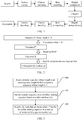
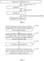
- a data transmission method provided in an embodiment of this application includes the following steps:
- Step 101 The network device sends, to a terminal, information about a time-frequency resource used for transmitting uplink data, where the time-frequency resource includes a plurality of time-frequency resource blocks, the information about the time-frequency resource includes each time-frequency resource block and configuration information corresponding to the time-frequency resource block, the configuration information includes at least identification information of the corresponding time-frequency resource block, and the identification information may be a start position or an index number of the time-frequency resource block; and optionally, before the terminal needs to send the uplink data, the network device sends, to the terminal, the information about the time-frequency resource used for transmitting the uplink data.
- Step 102 The terminal stores the plurality of time-frequency resource blocks and the corresponding configuration information that are allocated by the network device.
- Step 103 When the terminal needs to send the uplink data, the terminal selects, from the plurality of time-frequency resource blocks, at least one time-frequency resource block used for transmitting the uplink data.
- Step 104 The terminal transmits the uplink data on the at least one selected time-frequency resource block based on configuration information of the at least one selected time-frequency resource block.
- Step 105 The network device receives the uplink data sent by the terminal to the network device on the time-frequency resource block.
- the uplink transmission time-frequency resource pre-allocated by the network device to the terminal is divided into the plurality of time-frequency resource blocks, and therefore, the terminal may select a time-frequency resource with a relatively narrow bandwidth to transmit the uplink data, thereby increasing a transmit power of the terminal.
- the network device further configures the configuration information for each time-frequency resource block.
- the configuration information may carry a time-frequency resource block parameter or a coverage enhancement parameter, or both two parameters. Therefore, after selecting the time-frequency resource block used for transmitting the uplink data, the terminal transmits the uplink data based on the corresponding configuration information, to further increase a transmit power.
- the network device may further perform demodulation on a correct time-frequency resource block based on the configuration information, to improve demodulation efficiency and avoid generating a processing latency.
- the network device when dividing the uplink transmission resource in Manner 1, the network device associates the time-frequency resource block with the terminal group.
- Information used for the association process specifically includes:
- the information 3 may be sent to terminals in a same terminal group.
- Information 1 is a basic configuration for the terminal to perform grant-free transmission, and is used to indicate the uplink transmission time-frequency resource reserved by the network device for the terminal group or the terminal.
- Information 2 and Information 3 are optional, and a coverage enhancement parameter related to Information 2 and Information 3 is used to instruct the terminal to use the uplink transmission time-frequency resource to enhance coverage.
- the identification information in the configuration information of the time-frequency resource block may be a start position or an index number of the time-frequency resource block in Information 1.
- the network device may allocate an index number to each time-frequency resource block. Details are shown in Table 1: Table 1 Time-frequency resource block Index number Time-frequency resource block 1 1 Time-frequency resource block 2 2 Time-frequency resource block 3 3 Time-frequency resource block 4 4 Time-frequency resource block 5 5 Time-frequency resource block 6 6 Time-frequency resource block 7 7 Time-frequency resource block 8 8
- the terminal may send, to the network device, an index number of the time-frequency resource block selected by the terminal, so that the network device can perform accurate detection.
- Table 2 Time-frequency resource block Index number Terminal group to which a terminal belongs Time-frequency resource block 1 1 1 Time-frequency resource block 2 2 1 Time-frequency resource block 3 3 1 Time-frequency resource block 4 4 1 Time-frequency resource block 5 5 2 Time-frequency resource block 6 6 2 Time-frequency resource block 7 7 2 Time-frequency resource block 8 8 2
- Information 2 including the time-frequency resource block parameter or the coverage enhancement parameter is described in detail below.
- Information 1, Information 2, and Information 3 may be carried in a system message, RRC (radio resource control, radio resource control) signaling, a MAC CE (medium access control control element, medium access control control element), or DCI (downlink control information, downlink control information).
- RRC radio resource control, radio resource control
- MAC CE medium access control control element, medium access control control element
- DCI downlink control information, downlink control information
- Table 3 Process procedure System message RRC signaling MAC CE DCI Manner 1 Information 1 Information 2 and Information 3 Manner 2 Information 1 Information 2 Information 3 Manner 3 Information 1 Information 2 Information 3 Manner 4 Information 1 Information 2 and Information 3 Manner 5 Information 1 Information 2 Information 3 Manner 6 Information 1, Information 2, and Information 3 Manner 7 Information 1 Information 2 and Information 3 Manner 8 Information 1 Information 2 Information 3
- the network device when performing system configuration, may send Information 1 to the terminal by using a system message. Then when an RRC bearer is set up, the network device sends Information 2 and Information 3 to the terminal by using RRC signaling. In another manner, Information 1, Information 2, and Information 3 are carried in RRC signaling. In this case, signaling overheads are reduced and high flexibility is obtained.
- the network device may further send the configuration information to the terminal through more signaling combinations based on an actual requirement.
- RRC connection setup RRC Connection Setup
- configuration information carried in RRC includes division information of a time-frequency resource block, for example, a start position of the time-frequency resource block, so that the terminal can select a proper time-frequency resource block for transmission.
- a length of the time-frequency resource block extends to a start position of a next time-frequency resource block by default.
- the time-frequency resource block is a sub-band
- a message format of the time-frequency resource block is denoted as follows:
- time-frequency resource block is further divided into a smaller time-frequency resource block in a dimension of time domain based on a sub-band, in the foregoing configuration message, a start position in time domain is further carried, for example, a specific symbol.
- the uplink time-frequency resource may be alternatively first divided in a dimension of time domain, and then the uplink time-frequency resource is divided in a dimension of frequency domain to obtain a plurality of time-frequency resource blocks.
- Principles of subsequent embodiments are the same, and details are not described herein.
- configuration information carried in RRC includes division information of a time-frequency resource block, for example, a length of the time-frequency resource block, so that the terminal can select a proper time-frequency resource block for transmission, to increase a transmit power.
- a start position of a first time-frequency resource block in frequency domain may be a start position of an available sub-band, and a start position of a subsequent sub-band is "the start position of the available sub-band plus a length of all previous sub-bands plus 1".
- a start position of the first time-frequency resource block in time domain may be a start position of an available symbol, and a start position of a subsequent time-frequency resource block is "the start position of the available symbol plus a length of all previous symbols plus 1".
- the time-frequency resource block is a sub-band
- a message format of the time-frequency resource block is denoted as follows:
- configuration information carried in RRC includes division information of a time-frequency resource block, for example, a start position of the time-frequency resource block and a length of the time-frequency resource block, so that the terminal can select a proper time-frequency resource block for transmission, to increase a transmit power.
- the time-frequency resource block is a sub-band
- a message format of the time-frequency resource block is denoted as follows:
- time-frequency resource block is further divided into a smaller time-frequency resource block in a dimension of time domain based on a sub-band, in the foregoing message format, a start position and a length in time domain are further carried. For example, "a fourth symbol is at a start position and has a length of n".
- configuration information carried in RRC not only includes division information of a time-frequency resource block, but also includes a power control parameter corresponding to the time-frequency resource block.
- the network device may quantize a power level by using three bits. 000 represents that a transmit power of (1/2) 0 of a total power is used for transmission, and 001 represents that (1/2) 1 of a total power is used for transmission, and so on.
- the time-frequency resource block is a sub-band
- a message format of the time-frequency resource block is denoted as follows:
- time-frequency resource block is further divided into a smaller time-frequency resource block in a dimension of time domain, in the foregoing message format, a control control parameter of the time-frequency resource block may be indicated.
- NarrowbandConfigList field descriptions StartPoint Indicates a start position of a sub-band, where 0001 represents a first RB, 00 10 represents a second RB, and so on. Length Herein, n1 represents a length 1, n2 represents a length 2, n4 represents a length 4, and so on, where a transmission granularity set by a system is used as a unit.
- the network device may further define an upper limit of a quantity of time-frequency resource blocks.
- the network device may further define an end position of the time-frequency resource block.
- the division information of the time-frequency resource block may not include the length of the time-frequency resource block, and the length of the time-frequency resource block is from the start position to the end position of the time-frequency resource block.
- the time-frequency resource block is a sub-band
- the configuration information carried in the RRC includes the start position of the sub-band and the length of the sub-band.
- the following shows an example: EndPoint BIT STRING (SIZE(5)).
- the network device needs to define a new MAC CE and a corresponding MAC subheader (sub-header).
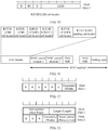
- Each sub-band is configured by using one MAC CE. If the network device needs to indicate configurations of a plurality of time-frequency resource blocks to the terminal, the network device sends a plurality of MAC CEs to the terminal.
- StartPoint Indicates a start position of a time-frequency resource block, where 0001 represents a first RB, 0010 represents a second RB, and so on. Length 0001 represents a length 1, 0001 represents a length 2, 0010 represents a length 4, and so on.
- PowerLeveL Quantizes a power level by using three bits, where 000 indicates that a transmit power of (1/2) 0 of a total power is used for transmission, and 001 indicates that (1/2) 1 of a total power is used for transmission, and so on.
- R Indicates a reserved bit.
- a corresponding MAC subheader is shown in FIG. 10 .
- an LCID (Logical Channel ID) corresponding to the newly defined MAC CE is shown in Table 4.
- a reserved field of TS 36321-e00, for example, 10111, can be used for the LCID to associate the newly defined MAC CE.
- Table 4 Values of an LCID for a downlink shared channel (Values of LCID for DL-SCH) Index value (Index) LCID value (LCID values) 00000 CCCH 00001-01010 Identity of a logical channel 01011-10110 Reserved 10111 Narrowband configuration 11000 Activation/Deactivation (four octets) 11001 SC-MCCH, SC-MTCH (see note) 11010 Long DRX command 11011 Activation/Deactivation (one octet) 11100 UE contention resolution identity 11101 Timing advance command 11110 DRX command 11111 Padding NOTE: Neither SC-MCCH nor SC-MTCH can be multiplexed with other logical channels in a same MAC PDU except for padding.
- indicating the MAC CE by using the reserved field 10111 is only an example. In another implementation, the MAC CE may be alternatively indicated by using another reserved field.
- the newly defined MAC CE may be carried in a newly defined MAC PDU (MAC Protocol Data Unit, MAC protocol data unit) format.
- the MAC CE may be alternatively carried in a MAC SDU on a DL-SCH (Downlink Shared Channel, downlink shared channel) defined in an existing LTE protocol.
- DL-SCH Downlink Shared Channel, downlink shared channel
- the network device may further configure a granularity of the time-frequency resource block, that is, the granularity of the time-frequency resource block may be further carried in the configuration information, and the granularity of the time-frequency resource block is a subcarrier, an RB (resource block), or an RBG (resource block group).
- the granularity of the time-frequency resource block is a subcarrier, an RB (resource block), or an RBG (resource block group).
- one RB includes 12 subcarriers.
- the network device may use 2-bit information to indicate a subcarrier, an RB, or an RBG, as shown in Table 5: Table 5 Sub-band granularity indication Description 00 Retained 01 Sub carrier 10 RB 11 RBG
- the configuration information is carried in the DCI, and the DCI is carried on a PDCCH (physical downlink control channel, physical downlink control channel).
- the PDCCH is scrambled by using an RNTI (radio network temporary identifier, radio network temporary identifier) of a terminal group, and the network device may perform configuration for one or more terminals in the terminal group.
- RNTI radio network temporary identifier, radio network temporary identifier
- the time-frequency resource block is a sub-band.
- DCI format includes the following information:
- length information of the sub-band may be further included in the DCI format: Length - 3 bits.
- Number of Narrowband provides a quantity of sub-bands configured in a current DCI message.
- Start Point represents a start position of the sub-band. 0001 represents starting from a first RB, 0010 represents starting from a second RB, and so on.
- Length represents a length of the sub-band. 0000 represents a length 1, 0001 represents a length 2, 0010 represents a length 4, and so on.
- an end position of a previous sub-band may be obtained through "a start position-1 of a current sub-band". Therefore, the configuration of the sub-bands may not include the length field.
- start position and an end position of the sub-band may be further configured.
- the configuration information that includes the sub-band granularity indication may be alternatively carried in a system message, RRC signaling, a MAC CE, or DCI. Details are described below.
- time-frequency resource block is further divided into a smaller time-frequency resource block in a dimension of time domain based on a sub-band, in the foregoing DCI message format, parameter information in time domain is included.
- the network device adds a new RRC information element (Radio resource control information elements) in the system message to indicate the granularity of the time-frequency resource block.
- RRC information element Radio resource control information elements
- the time-frequency resource block is a sub-band
- a message format of the time-frequency resource block is denoted as follows:
- Width Indicates a granularity of a sub-band, where 01 represents a subcarrier, 10 represents an RB, and 11 represents an RBG.
- Granularity indication information of the sub-band may be added to "RadioResourceConfigComm-onSIB" defined in LTE, and is transmitted by the network device to the terminal by using the system message.
- the time-frequency resource block is a sub-band
- a message format of the time-frequency resource block is denoted as follows:
- time-frequency resource block is divided into a smaller time-frequency resource block in a dimension of time domain, in the foregoing DCI message format, parameter information in time domain may be included. Principles of the embodiments are the same, and details are not described herein.
- the network device newly adds an RRC information element (Radio resource control information elements) to indicate the granularity of the time-frequency resource block.
- RRC information element Radio resource control information elements
- the time-frequency resource block is a sub-band
- a message format of the time-frequency resource block is denoted as follows:
- Width Indicates a granularity of a sub-band, where 01 represents a subcarrier, 10 represents an RB, and 11 represents an RBG.
- Granularity indication information of the sub-band may be added to "RRCConnectionSetup message” or "RRC ConnectionReconfiguration message” defined in LTE, and is transmitted by the network device to the terminal by using the RRC signaling.
- time-frequency resource block is divided into a smaller time-frequency resource block in a dimension of time domain, in the foregoing DCI message format, parameter information in time domain may be included.
- a new MAC CE is defined, and a corresponding LCID is defined. Specific representation is shown in FIG. 12 .
- Width Indicates a granularity of a time-frequency resource block, where 01 represents a subcarrier, 10 represents an RB, and 11 represents an RBG.
- R Indicates a reserved bit.
- LCID LCID value
- LCID values 00000 CCCH 00001-01010 Identity of a logical channel 01011-10101
- Reserved 10110 Narrowband width 10111 Narrowband configuration 11000 Activation/Deactivation (four octets) 11001 SC-MCCH, SC-MTCH (see note) 11010 Long DRX command 11011 Activation/Deactivation (one octet) 11100 UE contention resolution identity 11101 Timing advance command 11110 DRX command 11111 Padding NOTE: Neither SC-MCCH nor SC-MTCH can be multiplexed with other logical channels in
- the MAC CE may be alternatively indicated by using another reserved field.
- the newly defined MAC CE may be alternatively carried in a MAC PDU (MAC Protocol Data Unit, MAC protocol data unit) of a DL-SCH (Downlink Shared Channel, downlink shared channel) defined in an LTE protocol.
- MAC PDU MAC Protocol Data Unit, MAC protocol data unit
- DL-SCH Downlink Shared Channel, downlink shared channel
- Embodiment 6 based on the newly defined MAC CE shown in FIG. 9 in Embodiment 2, the fields are extended to indicate a granularity of a time-frequency resource block. Details are shown in FIG. 13 .
- StartPoint Indicates a start position of a time-frequency resource block, where 0001 represents a first RB, 0010 represents a second RB, and so on.
- Length 0000 represents a length 1, 0001 represents a length 2, 0010 represents a length 4, and so on.
- Width Indicates a granularity of a time-frequency resource block, where 01 represents a subcarrier, 10 represents an RB, and 11 represents an RBG.
- R Indicates a reserved bit.
- the value of the LCID corresponding to the MAC CE in Embodiment 2 remains unchanged, that is, there is no need to add a new LCID, and the value in Table 4 can be still used.
- the terminal may accumulate powers in time domain through TTI bundling or repetition transmission, to increase a demodulation signal-to-noise ratio of the network device.
- the network device may further configure a TTI bundling size or repetition size indication.
- the network device may perform demodulation by using a correct bundling size or repetition size.
- different bundling sizes may be configured for time-frequency resource blocks with a same bandwidth, to adapt to different service requirements of the terminal.
- the TTI bundling size indication or the repetition size indication may be implemented by adding a corresponding field of a TTI bundling size indication to the RRC signaling shown in Embodiment 1 or the MAC CE shown in Embodiment 2.
- the following still uses a TTI bundling size indication as an example for description in both Embodiment 7 and Embodiment 8.
- new RRC signaling still needs to be defined and is transferred during RRC connection setup.
- both a power control parameter and the TTI bundling size indication are carried in configuration information.
- the time-frequency resource block is a sub-band
- a message format of the time-frequency resource block is denoted as follows:
- time-frequency resource block is further divided into a smaller time-frequency resource block in a dimension of time domain based on a sub-band, in the foregoing DCI message format, parameter information in time domain is included.
- the TTI bundling size indication is carried but a power control parameter is not included in configuration information.
- the time-frequency resource block is a sub-band, and a message format of the time-frequency resource block is denoted as follows:
- n1 represents a length 1
- n2 represents a length 2
- n4 represents a length 4, and so on, where a minimum granularity of a resource scheduled in time domain may be used as a unit.
- time-frequency resource block is divided into a smaller time-frequency resource block in a dimension of time domain, in the foregoing DCI message format, parameter information in time domain may be included.
- the network device needs to define a new MAC CE, and one MAC CE is used for configuration of each time-frequency resource block. If the network device needs to indicate configurations of a plurality of time-frequency resource blocks to the terminal, the network device sends a plurality of MAC CEs to the terminal.
- both a power control parameter and the TTI bundling size indication are carried in configuration information.
- the new MAC CE may be defined in FIG. 14 . Meaning of fields are as follows: StartPoint Indicates a start position of a time-frequency resource block, where 0001 represents a first RB, 0010 represents a second RB, and so on. Length 0001 represents a length 1, 0001 represents a length 2, 0010 represents a length 4, and so on.
- n1 represents a length 1
- n2 represents a length 2
- n4 represents a length 4, and so on, where a minimum granularity of a resource scheduled in time domain may be used as a unit.
- R Indicates a reserved bit.
- the TTI bundling size indication is carried but a power control parameter is not included in configuration information.
- the new MAC CE may be defined in FIG. 15 . Meaning of fields are as follows: StartPoint Indicates a start position of a time-frequency resource block, where 0001 represents a first RB, 0010 represents a second RB, and so on. Length 0001 represents a length 1, 0001 represents a length 2, 0010 represents a length 4, and so on. Bundling size Herein, n1 represents a length 1, n2 represents a length 2, n4 represents a length 4, and so on, where a minimum granularity of a resource scheduled in time domain may be used as a unit. R Indicates a reserved bit.
- corresponding MAC subheaders (sub-header) need to be defined, and the corresponding MAC subheaders are shown in FIG. 10 . Details are not described herein.
- Embodiment 1 to Embodiment 8 describe, from a perspective of the network device based on Manner 1 in which the uplink transmission time-frequency resource used for grant-free transmission is divided into the plurality of time-frequency resource blocks associated with the terminal group, an implementation process of carrying the configuration information by using RRC, the MAC CE, the system message, and the DCI. Parameters carried in the configuration information are further divided into the power control parameter, the TTI bundling size indication, the granularity, the length, the index number of the time-frequency resource block, or the start position or the end position of the time-frequency resource block, and the like.
- Manner 1 The terminal randomly selects a time-frequency resource block for uplink transmission.
- the foregoing network device divides the uplink transmission time-frequency resource used for grant-free transmission into the plurality of time-frequency resource blocks associated with the terminal group, and configures the configuration information for each time-frequency resource block used for uplink transmission.
- the terminal selects, from time-frequency resource blocks of a terminal group to which the terminal belongs, one or more time-frequency resource blocks that meet a transmission requirement of the terminal, to perform uplink grant-free transmission.
- a terminal 1 belongs to a terminal group 1, and sub-bands that may be selected by the terminal 1 may include a time-frequency resource block 1-1, a time-frequency resource block 1-2, a time-frequency resource block 2, a time-frequency resource block 3, and a time-frequency resource block 4. If the terminal 1 selects a time-frequency resource block 4-1 to perform uplink transmission, the terminal 1 selects configuration information corresponding to the time-frequency resource block 4-1 to perform uplink transmission.
- Manner 2 The terminal selects a time-frequency resource block for uplink transmission based on a measurement result of channel quality.
- the terminal may select, based on the measurement result of channel quality, a time-frequency resource block for uplink grant-free transmission more accurately. Therefore, a better coverage enhancement effect can be obtained.
- SNR target represents a target signal-to-noise ratio
- Pathloss represents a path loss, and the path loss can be obtained through measurement. This is a technical means well known to a person skilled in the art. Details are not described herein.
- P noise represents a noise power
- P_ul_tx represents an uplink transmit power
- P_ul_tx is obtained through calculation according to formula (2):
- P _ ul _ tx P _ ul _ total ⁇ 10 ⁇ log Num _ RB ⁇ TTI bundlingsize
- P_ul_total represents a total transmit power allowed for uplink transmission.
- Num_RB ⁇ TTI bundlingsize 10 ⁇ (P_ul_total - Pathloss - P_noise)/10 (3).
- a value of TTIbundling size is 1.
- the terminal may obtain a quantity of time-frequency resource blocks for uplink transmission through calculation according to formula (3), search for configuration information based on the quantity of time-frequency resource blocks, and select a time-frequency resource block corresponding to the configuration information to perform uplink grant-free transmission.
- a process of selecting a corresponding time-frequency resource block by calculating a quantity of time-frequency resource blocks for uplink transmission is described herein.
- parameters such as a power required for uplink transmission, a granularity of a time-frequency resource block, or a TTI bundling size indication or a repetition size indication may be further calculated and then a corresponding time-frequency resource block is selected.
- a calculation formula for the time-frequency resource block is set as required. Details are not described herein.
- Manner 3 The terminal selects a time-frequency resource block for uplink transmission based on a previous statistical result of a success rate of data transmission.
- the terminal when performing initial transmission, may randomly select a time-frequency resource block, or select a proper time-frequency resource block based on a value of pathloss (Pathloss) to perform uplink transmission.
- Pathloss pathloss
- the terminal when the terminal receives a NACK message from the network device N times, selection of a time-frequency resource block with a relatively narrow bandwidth to perform uplink transmission is triggered.
- the terminal may select a time-frequency resource block with a relatively wide bandwidth to perform uplink transmission.
- the network device may configure a threshold of N, so that the terminal can collect statistics about whether data transmission succeeds.
- Manner 4 The terminal selects at least one time-frequency resource block for uplink transmission based on a transmit power required by the terminal.
- the terminal After selecting the time-frequency resource block based on any one of the four manners, the terminal performs uplink transmission based on configuration information (for example, a coverage enhancement parameter or a time-frequency resource block parameter) corresponding to the time-frequency resource block.
- configuration information for example, a coverage enhancement parameter or a time-frequency resource block parameter
- CRC Cyclic redundancy check, cyclic redundancy check
- scrambling is performed by using a terminal ID or an inner group identity number (inner Group ID).
- a pilot (pilot), a reference signal (RS, reference Signal), or a preamble (preamble sequence) used when the network device performs terminal detection is selected from a corresponding terminal group configuration. Pilots may be in a one-to-one correspondence with terminals, to perform terminal identification.
- the terminal ID may be a C-RNTI (Cell-Radio Network Temporary Identity, cell radio network temporary identity), or may be an inner group identity number (inner Group ID).
- the C-RNTI is configured in an access process or a handover process.
- the inner group identity number is provided during terminal group resource configuration.
- a base station may demodulate new data through blind demodulation, that is, process data processing at a previously configured time-frequency resource block position.
- a start position or an index number of each possible time-frequency resource block has been preset. Therefore, the base station only needs to make attempts for a small quantity of times.
- the terminal may send uplink data and send uplink control signaling that carries a resource selection result simultaneously, and a transmission time-frequency resource block selected by the terminal is notified to the network device, for example, indicating by using identification information of the time-frequency resource block (for example, a start position or an index number of the time-frequency resource block). Further, another parameter configuration, for example, a TTI bundling size, selected by the terminal for transmission on the time-frequency resource block may be reported.
- a time-frequency resource for sending the signaling may be pre-agreed with the base station, and the base station is associated with the terminal by using a resource position.
- the terminal ID may be carried in the uplink control signaling.
- the base station After receiving the signaling, the base station identifies the terminal and time-frequency resource block information used by the terminal, and correspondingly receives the time-frequency resource block information.
- the foregoing describes an implementation of performing uplink transmission by the terminal based on the configuration information and a condition that the network device configures the time-frequency resource block to be associated with a terminal group.
- the following describes an implementation process in which the network device configures corresponding configuration information for each time-frequency resource block based on a condition that the network device configures a sub-band not to be associated with a terminal group.
- the network device may allocate an index number to each time-frequency resource block. Details are shown in Table 8: Table 8 Time-frequency resource block Index number Time-frequency resource block 1 I Time-frequency resource block 2 2 Time-frequency resource block 3 3 Time-frequency resource block 4 4 Time-frequency resource block 5 5 Time-frequency resource block 6 6 Time-frequency resource block 7 7 Time-frequency resource block 8 8
- the terminal may send, to the network device, an index number of the time-frequency resource block selected by the terminal, so that the network device can perform accurate detection.
- Time-frequency resource block Index number Terminal to which the time-frequency resource block belongs Time-frequency resource block 1 1 1 Time-frequency resource block 2 2 2 Time-frequency resource block 3 3 3 Time-frequency resource block 4 4 4 Time-frequency resource block 5 5 5 Time-frequency resource block 6 6 6 Time-frequency resource block 7 7 7 Time-frequency resource block 8 8 8
- Information 2 including the time-frequency resource block parameter or the coverage enhancement parameter is described in detail below.
- Information 2 may be broadcast by the network device at a system level.
- the information 2 is sent to the terminal by using a system message, or may be configured by using RRC signaling or a MAC CE after the terminal completes connection setup. It should be understood that, in a manner of carrying information by using RRC signaling, signaling overheads for sending Information 1 and Information 2 are reduced and more flexibility is obtained.
- the following embodiments describe configuration information of the time-frequency resource blocks and a configuration information carrying manner when the plurality of time-frequency resource blocks obtained by dividing the uplink transmission time-frequency resource are specifically in a form of a plurality of sub-bands.
- the time-frequency resource block is further divided into smaller time-frequency resource blocks in a dimension of time domain, corresponding slots or symbol identifiers are added to indication manners such as start positions, a quantity, lengths, and the like of the smaller time-frequency resource blocks.
- Embodiment 9 is similar to Embodiment 1.
- New RRC signaling is defined to carry the configuration information, and the configuration information is sent to the terminal by using an RRC connection setup message "RRCConnectionSetup message” or an RRC connection reconfiguration message "RRC ConnectionReconfiguration message”.
- a message format and a field meaning of the time-frequency resource block are the same as those in Embodiment 1.
- configuration information that includes a granularity indication of a time-frequency resource block may be also carried in the RRC signaling; and similar to Embodiment 7, configuration information that includes a TTI bundling size indication or a repetition size indication may be also carried in the RRC signaling.
- TTI bundling size indication or a repetition size indication may be also carried in the RRC signaling.
- the network device also needs to define a new MAC CE and a corresponding MAC subheader (sub-header).
- a specific message format and a field definition of a time-frequency resource block are also the same as those in Embodiment 2.
- configuration information that includes a granularity indication of a time-frequency resource block may be also carried in a MAC CE; and similar to Embodiment 8, configuration information that includes a TTI bundling size indication or a repetition size indication may be also carried in the MAC CE.
- TTI bundling size indication or a repetition size indication may be also carried in the MAC CE.
- a new element also needs to be defined through same definition as the definition of the element used for transmission by using the RRC signaling.
- the newly added element may be added to "RadioResourceConfigCommonSIB" defined in an existing LTE protocol, and is transmitted to the terminal by the system message.
- the configuration information that includes a granularity indication of a time-frequency resource block may be also carried in the system message.
- Embodiment 9 to Embodiment 11 describe, from a perspective of the network device based on Manner 2 in which the uplink transmission time-frequency resource used for grant-free transmission is divided into the plurality of time-frequency resource blocks (not associated with the terminal group), an implementation process of carrying the configuration information by using RRC, the MAC CE, the system message, and the DCI. Parameters carried in the configuration information are further divided into a power control parameter, the TTI bundling size indication or repetition size indication, the granularity, the length, and the index number of the time-frequency resource block, the start position or an end position of the time-frequency resource block, and the like.
- the terminal when the terminal selects a time-frequency resource block, there are also the following four implementations: 1. Selection is randomly performed. 2. Selection is performed based on a measurement result of channel quality. 3. Selection is performed based on a previous statistical result of a success rate of data transmission. 4. Selection is performed based on a transmit power requirement.
- each terminal when sending uplink data during uplink grant-free transmission, each terminal needs to add a terminal identifier to the uplink data, for example, carry the terminal identifier by using the MAC CE or the RRC signaling.
- a pilot (pilot), a reference signal (RS, reference Signal), or a preamble (preamble sequence) corresponding to the time-frequency resource block are not allocated to a fixed terminal or terminal group. Consequently, terminals cannot be distinguished.
- an ID corresponding to a time-frequency resource block instead of a terminal ID is used for data scrambling.
- This sub-band ID is corresponding only to a time-frequency resource block instead of being allocated to a fixed terminal or terminal group.
- a pilot (pilot), a reference signal (RS, reference Signal), or a preamble (preamble sequence) used when the network device performs terminal detection is selected from a corresponding time-frequency resource block configuration.
- the network device performs CRC processing by using an ID of a time-frequency resource block, and further processes or distributes the uplink data based on the terminal ID in the uplink data.
- the ID of the time-frequency resource block may be a C-RNTI (Cell-Radio Network Temporary Identity, cell radio network temporary identity), or may be a newly defined RNTI that can distinguish a plurality of time-frequency resource blocks in a cell, and the ID of the time-frequency resource block is sent by the network device to the terminal together with the configuration information of the time-frequency resource block.
- C-RNTI Cell-Radio Network Temporary Identity, cell radio network temporary identity
- the terminal ID may be a C-RNTI or a global subscriber identifier, for example, an international mobile subscriber identity (International Mobile Subscriber Identification Number, IMSI for short), or a temporary mobile subscriber identify (Temporary Mobile Subscriber Identity, TMSI for short).
- IMSI International Mobile Subscriber Identification Number
- TMSI Temporal Mobile Subscriber Identity
- the ID of the time-frequency resource block or the terminal ID may be carried in signaling such as a SIB (system information block, system information block), an RRC, or a MAC CE.
- SIB system information block, system information block
- RRC Radio Resource Control
- MAC CE MAC CE
- the foregoing embodiments describe the following implementations based on a condition that the network device divides the uplink transmission time-frequency resource used for uplink grant-free transmission into the pluralities of time-frequency resource blocks: a manner in which the network device configures the corresponding configuration information, and a manner in which the terminal selects the time-frequency resource block and performs the uplink grant-free transmission by using the configuration information.
- the configuration information a start position or a length of a sub-band of the time-frequency resource block is represented by using a character.
- a value of the field “StartPoint” if a value of the field “StartPoint” is 0001, it represents that a start position of the time-frequency resource block is a first RB; and 0010 represents that a start position of the time-frequency resource block is a second RB, and so on.
- a field “Length” if a value of the field “Length” is 0001, it represents a length 1, 0001 represents a length 2, 0010 represents a length 4, and so on.
- configuration information corresponding to different sub-bands may be further represented by using a pilot pattern or a pilot sequence. Details are described below. It should be noted that, when a time-frequency resource block is further divided into smaller time-frequency resource blocks in a dimension of time domain, corresponding slots or symbol identifiers are added to indication manners such as start positions, a quantity, lengths, and the like of the smaller time-frequency resource blocks. Details are not described herein.
- the terminal When transmitting data, the terminal needs to further send a pilot, to perform channel estimation and data demodulation. As a bandwidth changes, in consideration of efficiency and performance, different pilot patterns are defined in the protocol.
- the time-frequency resource block uses a subcarrier as a granularity to define a new pilot pattern. For example, as shown in FIG. 16 , a pilot pattern in a case of one subcarrier, a pilot pattern in a case of two subcarriers, and a pilot pattern in a case of four subcarriers. Only examples are provided herein.
- an index number or a start position of the time-frequency resource block can be obtained only by sequentially indicating a pilot pattern used by each time-frequency resource block. Details are shown in Embodiment 12.
- Embodiment 2 This embodiment is similar to Embodiment 1.
- a new RRC information element (Radio resource control information element) is defined, and is placed, for transmission, in an RRC message - RRCConnectionSetup.
- the time-frequency resource block is a sub-band
- a message format of the time-frequency resource block is denoted as follows:
- rsp1 represents a pilot pattern for a sub-band width of one subcarrier
- rsp2 represents a pilot pattern for a sub-band width of two subcarriers, and so on.
- the message format describes an implementation in which the plurality of time-frequency resource blocks obtained by dividing the uplink transmission time-frequency resource are specifically in a form of sub-bands.
- the time-frequency resource block is divided into smaller time-frequency resource blocks in a dimension of time domain, corresponding slots or symbol identifiers are added to indication manners such as index numbers, start positions, a quantity, lengths, end positions, and the like of the smaller time-frequency resource blocks.
- configuration information that includes a TTI bundling size indication or a repetition size indication may be also carried in the RRC signaling.
- TTI bundling size indication or a repetition size indication may be also carried in the RRC signaling.
- the configuration information is carried in the RRC signaling. This is used only as an example. Configuration information that includes a pilot pattern may be further carried in a MAC CE, DCI, or a system message.
- a new pilot pattern may be further defined to indicate a granularity (Width) of a time-frequency resource block, where the granularity may be a subcarrier, an RB, or an RBG.
- FIG. 17 shows pilot patterns when granularities of sub-bands are a subcarrier, an RB, and an RBG (including three RBs). This is used only as an example herein.
- This embodiment is similar to Embodiment 1.
- a new RRC information element (Radio resource control information element) is defined, and is placed, for transmission, in an RRC message - RRCConnectionSetup.
- the time-frequency resource block is a sub-band
- a message format of the time-frequency resource block is denoted as follows:
- rsp1 represents a pilot pattern when a granularity of a sub-band is a subcarrier
- rsp2 represents a pilot pattern when a granularity of a sub-band is an RB, and so on.
- configuration information that includes a TTI bundling size indication or a repetition size indication may be also carried in the RRC signaling.
- TTI bundling size indication or a repetition size indication may be also carried in the RRC signaling.
- An index number, a start position, and an end position of a sub-band, a quantity of sub-bands, and a granularity of a time-frequency resource block may be indicated by using the pilot pattern.
- representation of another field is similar to that in Embodiment 1 to Embodiment 12. For brevity, details are not described herein.
- start positions or a quantity of time-frequency resource blocks may be further indicated by using a pilot sequence.
- X q n e ⁇ j ⁇ qn n + 1 N ZC RS , 0 ⁇ n ⁇ N ZC RS ⁇ 1 .
- N ZC RS represents a length of a ZC sequence
- n represents a sequence element number
- q represents a root (root) of the ZC sequence.
- Different roots are corresponding to different ZC sequences.
- the network device determines a start position of a corresponding time-frequency resource block or a quantity of corresponding time-frequency resource blocks by detecting a specific sequence sent by the terminal.
- a corresponding time-frequency resource block for transmission is selected.
- a selection manner is similar to that in the foregoing embodiment. There are the following four implementations: 1. Selection is randomly performed. 2. Selection is performed based on a measurement result of channel quality. 3. Selection is performed based on a previous statistical result of a success rate of data transmission. 4. Selection is performed based on a transmit power requirement. For brevity, details are not described herein.
- the pilot sequence being the ZC (Zadoff-Chu) sequence is only an example.
- the pilot sequence may be further an activity detection reference signal (Activity Detection Reference Signal, ADRS for short), a pseudo-noise sequence (Pseudo-Noise Sequence), also referred to as a PN sequence, an M sequence, Walsh code, or the like.
- ADRS Activity Detection Reference Signal
- Pseudo-Noise Sequence also referred to as a PN sequence
- M sequence an M sequence
- Walsh code or the like.
- this embodiment of the present invention is not limited thereto.
- pilot sequences mapped to a same sub-band may be distinguished by using cyclic shift values and root numbers.
- the pilot sequence is the M sequence
- terminals mapped to a same sub-band may be distinguished by using cyclic shift values.
- pilot sequences of the terminals mapped to the same sub-band are corresponding to different cyclic shift values.
- sequence numbers of the foregoing processes do not mean execution sequences.
- the execution sequences of the processes should be determined based on functions and internal logic of the processes, and shall not constitute any limitation on the implementation processes of the embodiments of this application.
- a terminal 500 provided in this embodiment of this application includes at least a processor 504 and a transceiver 508.
- the terminal may further include a memory 519, and the memory 519 stores a computer-executable instruction.
- the processor 504 is configured to obtain a time-frequency resource used to transmit uplink data, where the time-frequency resource is at least one time-frequency resource block selected from a plurality of time-frequency resource blocks, each of the time-frequency resource blocks is corresponding to one piece of configuration information, and the configuration information includes at least identification information of the corresponding time-frequency resource block.
- the transceiver 508 is configured to transmit, based on the configuration information of the at least one time-frequency resource block selected by the processor 504, transmit the uplink data on the at least one selected time-frequency resource block.
- the processor 504 may be configured to perform an action implemented by the terminal in the foregoing method embodiments, and the transceiver 508 may be configured to perform a transmitting action or a sending action by the terminal to the network device in the foregoing method embodiments.
- the transceiver 508 may be configured to perform a transmitting action or a sending action by the terminal to the network device in the foregoing method embodiments.
- the processor 504 and the memory 519 may be integrated into one processing apparatus.
- the processor 504 is configured to execute program code stored in the memory 519 to implement the foregoing functions.
- the memory 519 may be alternatively integrated into the processor 504.
- the terminal may further include a power supply 512, and the power supply 512 is configured to supply power to various components or circuits of the terminal.
- the terminal may include an antenna 510, and the antenna 510 is configured to send, by using a radio signal, uplink data or uplink control signaling output by the transceiver 508.
- the terminal may further include one or more of an input unit 514, a display unit 516, an audio circuit 518, a camera 520, a sensor 522, or the like.
- the audio circuit may further include a loudspeaker 5182, a microphone 5184, and the like.
- a network device provided in an embodiment of this application includes at least a processor 604 and a transceiver 608.
- the network device may further include a memory 603, and the memory 603 is configured to store information about a time-frequency resource used to transmit uplink data.
- the time-frequency resource includes a plurality of time-frequency resource blocks.
- the transceiver 608 of the network device is configured to send, to a terminal, the information about the time-frequency resource used to transmit the uplink data, where the time-frequency resource includes the plurality of time-frequency resource blocks; the information about the time-frequency resource includes each time-frequency resource block and configuration information corresponding to the time-frequency resource block; and the configuration information includes at least identification information of the corresponding time-frequency resource block.
- the processor 604 is configured to detect, on at least one time-frequency resource block selected by the terminal, the uplink data transmitted by the terminal.
- the processor 604 and the memory 603 may be integrated into one processing apparatus.
- the processor 604 is configured to execute program code stored in the memory 603 to implement the foregoing functions.
- the memory 603 may be alternatively integrated into the processor 604.
- the processor 604 of the network device is further configured to divide an uplink transmission time-frequency resource into a plurality of time-frequency resource blocks.
- Corresponding configuration information is configured for each of the time-frequency resource blocks.
- the memory 603 is configured to store the uplink transmission time-frequency resource divided by the processor 604 into the plurality of time-frequency resource blocks.
- Corresponding configuration information is configured for each of the time-frequency resource blocks.
- the uplink transmission time-frequency resource divided into the plurality of time-frequency resource blocks and the corresponding configuration information may be prestored in the memory 603 in a form of table by a person responsible for system configuration, or may be stored in the memory 603 after the processor 604 divides the uplink transmission time-frequency resource into the time-frequency resource blocks and configures the corresponding configuration information.
- the transceiver 608 of the network device sends, to the terminal, the plurality of time-frequency resource blocks and the corresponding configuration information.
- the transceiver 608 of the network device is further configured to receive the uplink data sent by the terminal to the network device based on the corresponding configuration information on the time-frequency resource block selected by the terminal.
- the network device may further include an antenna 610, and the antenna 610 is configured to send, by using a radio signal, downlink data or downlink control signaling output by the transceiver 608.
- the processor 504 of the terminal and the processor 604 of the network device may be central processing units (central processing unit, CPU for short), network processors (network processor, NP for short), or a combination of the CPUs and the NPs.
- the processor may further include a hardware chip.
- the hardware chip may be an application-specific integrated circuit (application-specific integrated circuit, ASIC for short), a programmable logic device (programmable logic device, PLD for short), or a combination thereof.
- the PLD may be a complex programmable logic device (complex programmable logic device, CPLD for short), a field-programmable gate array (field-programmable gate array, FPGA for short), a generic array logic (generic array logic, GAL for short), or any combination thereof.
- the memory 12 of the terminal and the memory 22 of the network device may include a volatile memory (volatile memory), such as a random access memory (random access memory, RAM for short), or may include a non-volatile memory (non-volatile memory), such as a flash memory (flash memory), a hard disk drive (hard disk drive, HDD for short), or a solid-state drive (solid-state drive, SSD for short).
- volatile memory such as a random access memory (random access memory, RAM for short
- non-volatile memory such as a flash memory (flash memory), a hard disk drive (hard disk drive, HDD for short), or a solid-state drive (solid-state drive, SSD for short.
- flash memory flash memory
- HDD hard disk drive
- SSD solid-state drive
- the terminal may perform wireless communication with the network device through the foregoing grant-free transmission.
- the terminal may alternatively perform wireless communication through grant-based spectrum resource transmission.
- the network device in the apparatus embodiment of this application may be corresponding to the network device in the method Embodiment 1 to the method Embodiment 12 in this application, and the terminal may be corresponding to the terminal in the method Embodiment 1 to the method Embodiment 12 in this application.
- the foregoing and other operations and/or functions of the modules of the network device and the terminal are used to implement corresponding procedures in Embodiment 1 to Embodiment 12.
- the descriptions of the method embodiments of this application are applicable to the apparatus embodiments. Details are not described herein.
- the uplink transmission time-frequency resource pre-allocated by the network device to the terminal is divided into a plurality of uplink transmission time-frequency resources in a form of time-frequency resource blocks. Therefore, the terminal may select a time-frequency resource with a relatively narrow bandwidth to perform uplink transmission, thereby increasing a transmit power of the terminal. Further, the network device further configures the configuration information for each time-frequency resource block. The configuration information may carry the time-frequency resource block parameter or the coverage enhancement parameter, or both parameters. Therefore, after selecting the time-frequency resource block used for uplink transmission, the terminal performs the uplink transmission based on the corresponding configuration information, to further increase a transmit power. In addition, the network device may perform demodulation on a correct time-frequency resource block based on the configuration information, to improve demodulation efficiency and avoid generating a processing latency.
- the disclosed system, apparatus, and method may be implemented in another manner.
- the described apparatus embodiment is only an example.
- the unit division is only logical function division and may be other division in actual implementation.
- a plurality of units or components may be combined or integrated into another system, or some features may be ignored or may not be performed.
- the indicated or discussed mutual couplings or direct couplings or communication connections may be implemented through some interfaces.
- the indirect couplings or communication connections between the apparatuses or units may be implemented in electronic, mechanical, or other forms.
- the units described as separate parts may or may not be physically separate, and parts displayed as units may or may not be physical units, may be located in one position, or may be distributed on a plurality of network units. Some or all of the units may be selected based on actual requirements to achieve the objectives of the solutions of the embodiments.
- the computer software product is stored in a storage medium and includes several instructions for instructing a computer device (which may be a personal computer, a server, a network device, or the like) to perform all or some of the steps of the methods described in the embodiments of this application.
- the storage medium includes various media that can store program code, such as a USB flash drive, a removable hard disk, a read-only memory (ROM, Read-Only Memory), a random access memory (RAM, Random Access Memory), a magnetic disk, or an optical disc.
Landscapes
- Engineering & Computer Science (AREA)
- Signal Processing (AREA)
- Computer Networks & Wireless Communication (AREA)
- Quality & Reliability (AREA)
- Mobile Radio Communication Systems (AREA)
Applications Claiming Priority (2)
| Application Number | Priority Date | Filing Date | Title |
|---|---|---|---|
| CN201710214560.0A CN108668367B (zh) | 2017-04-01 | 2017-04-01 | 一种数据传输方法、网络设备和终端 |
| PCT/CN2018/080551 WO2018177259A1 (fr) | 2017-04-01 | 2018-03-26 | Procédé de transmission de données, dispositif de réseau, et terminal |
Publications (3)
| Publication Number | Publication Date |
|---|---|
| EP3595346A1 true EP3595346A1 (fr) | 2020-01-15 |
| EP3595346A4 EP3595346A4 (fr) | 2020-03-18 |
| EP3595346B1 EP3595346B1 (fr) | 2023-12-27 |
Family
ID=63675201
Family Applications (1)
| Application Number | Title | Priority Date | Filing Date |
|---|---|---|---|
| EP18777036.7A Active EP3595346B1 (fr) | 2017-04-01 | 2018-03-26 | Procédé de transmission de données, dispositif de réseau, et terminal |
Country Status (5)
| Country | Link |
|---|---|
| US (1) | US11464006B2 (fr) |
| EP (1) | EP3595346B1 (fr) |
| CN (1) | CN108668367B (fr) |
| BR (1) | BR112019020240A2 (fr) |
| WO (1) | WO2018177259A1 (fr) |
Cited By (1)
| Publication number | Priority date | Publication date | Assignee | Title |
|---|---|---|---|---|
| EP4084549A4 (fr) * | 2019-12-26 | 2023-02-08 | Datang Mobile Communications Equipment Co., Ltd. | Procédé et appareil de communication |
Families Citing this family (22)
| Publication number | Priority date | Publication date | Assignee | Title |
|---|---|---|---|---|
| CN107370701B (zh) * | 2016-05-11 | 2020-05-08 | 华为技术有限公司 | 传输信号的方法、发送端和接收端 |
| KR102353972B1 (ko) * | 2017-04-11 | 2022-01-21 | 삼성전자 주식회사 | 무선 통신 시스템에서 서브프레임 결합을 이용한 신호 복조 방법 및 장치 |
| EP4216481B1 (fr) | 2017-06-07 | 2026-05-06 | Guangdong Oppo Mobile Telecommunications Corp., Ltd. | Procédé et appareil de communication sans fil |
| CN109121166A (zh) * | 2017-06-22 | 2019-01-01 | 维沃移动通信有限公司 | 一种数据传输方法、基站和用户终端 |
| CN109219113B (zh) * | 2017-07-05 | 2020-07-17 | 维沃移动通信有限公司 | 一种盲检测方法、信号发送方法、相关设备和系统 |
| EP3726914B1 (fr) | 2017-08-10 | 2024-07-24 | Comcast Cable Communications, LLC | Activation de transmission sans subvention |
| JP7111806B2 (ja) * | 2017-10-11 | 2022-08-02 | テレフオンアクチーボラゲット エルエム エリクソン(パブル) | グラントフリーpuschにおけるuci |
| WO2019090720A1 (fr) * | 2017-11-10 | 2019-05-16 | Oppo广东移动通信有限公司 | Procédé et dispositif de transmission de données |
| US20200014599A1 (en) * | 2018-07-06 | 2020-01-09 | Qualcomm Incorporated | Apparatus and method for requesting narrower bandwidth channel to address communication link issue |
| JP7284258B2 (ja) | 2018-10-30 | 2023-05-30 | オッポ広東移動通信有限公司 | リソース構成方法、ネットワークデバイス及び端末デバイス |
| CN111132318B (zh) * | 2018-10-31 | 2022-07-19 | 华为技术有限公司 | 一种资源调度方法和装置 |
| WO2020087468A1 (fr) | 2018-11-01 | 2020-05-07 | Oppo广东移动通信有限公司 | Procédé et dispositif de communication sans fil |
| CN111181707B (zh) * | 2018-11-09 | 2022-11-04 | 华为技术有限公司 | 数据传输的方法和通信装置 |
| CN109792763B (zh) * | 2018-12-20 | 2022-09-23 | 北京小米移动软件有限公司 | 数据传输方法及装置 |
| CN111436135A (zh) * | 2019-01-11 | 2020-07-21 | 华为技术有限公司 | 数据传输方法及装置 |
| WO2020147054A1 (fr) * | 2019-01-16 | 2020-07-23 | Oppo广东移动通信有限公司 | Procédé d'indication destiné à la réplication et à la transmission de données, dispositif terminal, et dispositif de réseau |
| CN112714441B (zh) | 2019-10-24 | 2024-06-14 | 华为技术有限公司 | 一种数据传输方法、通信装置及通信系统 |
| US11653343B2 (en) * | 2020-03-13 | 2023-05-16 | Huawei Technologies Co., Ltd. | Spectrum allocation for multiple resource units in a wireless network |
| US11882576B2 (en) * | 2020-05-01 | 2024-01-23 | Qualcomm Incorporated | Techniques for dynamic signaling for wireless coverage enhancement |
| CN113973388B (zh) * | 2020-07-22 | 2025-04-25 | 维沃移动通信有限公司 | 取消传输的方法、终端及网络侧设备 |
| US12513647B2 (en) * | 2020-08-11 | 2025-12-30 | Beijing Xiaomi Mobile Software Co., Ltd. | Method for resource processing, and communication device |
| CN114071682B (zh) * | 2021-11-04 | 2023-05-16 | 中国联合网络通信集团有限公司 | 一种分布式网络架构的功率选择方法及装置 |
Family Cites Families (14)
| Publication number | Priority date | Publication date | Assignee | Title |
|---|---|---|---|---|
| US7697948B2 (en) * | 2004-10-29 | 2010-04-13 | Telefonaktiebolaget L M Ericsson (Publ) | Resource allocation in communication networks |
| CN105515747B (zh) * | 2007-04-27 | 2019-04-19 | 华为技术有限公司 | 资源请求指示信息的时频资源分配方法、装置及基站 |
| CN101345974B (zh) * | 2007-07-09 | 2011-08-31 | 电信科学技术研究院 | 一种调度移动终端发送上行信道探测导频的方法及系统 |
| EP2760235B1 (fr) * | 2007-11-05 | 2018-05-16 | Apple Inc. | Procédés et systèmes pour l'attribution de ressources |
| CN101227698B (zh) * | 2008-02-03 | 2010-06-23 | 普天信息技术研究院有限公司 | 一种资源调整的方法 |
| KR101672769B1 (ko) * | 2010-02-09 | 2016-11-04 | 삼성전자주식회사 | 겹치는 무선 자원을 이용하여 업링크 통신 및 다운링크 통신을 수행하는 통신 시스템 |
| US8416741B2 (en) * | 2010-09-07 | 2013-04-09 | Verizon Patent And Licensing Inc. | Machine-to-machine communications over fixed wireless networks |
| US9504027B2 (en) * | 2010-11-25 | 2016-11-22 | Lg Electronics Inc. | Method and apparatus for transmitting a control channel and a data channel in a wireless communication system |
| WO2014035085A1 (fr) * | 2012-08-28 | 2014-03-06 | 엘지전자 주식회사 | Procédé de détection de canal de commande de liaison descendante dans un système de communication sans fil et appareil associé |
| US10028302B2 (en) * | 2013-03-08 | 2018-07-17 | Huawei Technologies Co., Ltd. | System and method for uplink grant-free transmission scheme |
| CN105491665B (zh) * | 2014-09-15 | 2019-07-23 | 中兴通讯股份有限公司 | 导频配置方法及装置 |
| CN104936133B (zh) * | 2015-05-29 | 2019-01-25 | Oppo广东移动通信有限公司 | 机器类型通信的方法、基站以及终端 |
| WO2016209055A1 (fr) * | 2015-06-26 | 2016-12-29 | 엘지전자 주식회사 | Procédé et appareil permettant d'émettre un signal de balayage de faisceau de liaison montante dans un système de communication sans fil |
| US9743423B2 (en) * | 2015-07-27 | 2017-08-22 | Futurewei Technologies, Inc. | Link adaptation in grant-free multiple access systems |
-
2017
- 2017-04-01 CN CN201710214560.0A patent/CN108668367B/zh active Active
-
2018
- 2018-03-26 WO PCT/CN2018/080551 patent/WO2018177259A1/fr not_active Ceased
- 2018-03-26 EP EP18777036.7A patent/EP3595346B1/fr active Active
- 2018-03-26 BR BR112019020240-4A patent/BR112019020240A2/pt not_active Application Discontinuation
-
2019
- 2019-09-25 US US16/581,752 patent/US11464006B2/en active Active
Cited By (1)
| Publication number | Priority date | Publication date | Assignee | Title |
|---|---|---|---|---|
| EP4084549A4 (fr) * | 2019-12-26 | 2023-02-08 | Datang Mobile Communications Equipment Co., Ltd. | Procédé et appareil de communication |
Also Published As
| Publication number | Publication date |
|---|---|
| BR112019020240A2 (pt) | 2020-04-22 |
| WO2018177259A1 (fr) | 2018-10-04 |
| EP3595346A4 (fr) | 2020-03-18 |
| CN108668367A (zh) | 2018-10-16 |
| EP3595346B1 (fr) | 2023-12-27 |
| US20200022125A1 (en) | 2020-01-16 |
| CN108668367B (zh) | 2020-06-02 |
| US11464006B2 (en) | 2022-10-04 |
Similar Documents
| Publication | Publication Date | Title |
|---|---|---|
| US11464006B2 (en) | Data transmission method, network device, and terminal | |
| US11553435B2 (en) | Uplink information transmission method and apparatus | |
| CN111837446B (zh) | 随机接入的方法和通信设备 | |
| KR102732969B1 (ko) | 협대역 무선 통신을 위한 랜덤 액세스 채널 설계 | |
| WO2022028374A1 (fr) | Procédé et appareil de répétition de pusch dans une procédure d'accès aléatoire | |
| JP7634335B2 (ja) | 2ステップランダムアクセスプロシージャにおける無線ネットワーク一時識別子を決定するための方法および装置 | |
| WO2020221264A1 (fr) | Procédé d'accès aléatoire, appareil, et support de stockage | |
| CN119766407A (zh) | 用于上行链路传输的波形配置和指示 | |
| WO2018129987A1 (fr) | Procédé de transmission non autorisée, dispositif terminal, et dispositif de réseau | |
| CN114208300B (zh) | 两步随机接入中接收和发送随机接入响应的方法及装置 | |
| EP4258754A1 (fr) | Procédé et appareil de détermination d'une puissance d'émission | |
| US20250055624A1 (en) | Sounding reference signal and hybrid automatic repeat request for new radio-unlicensed | |
| WO2022196833A1 (fr) | Appareil équipement utilisateur, appareil station de base et procédé de communication | |
| CN111989978B (zh) | 随机接入的方法和设备 | |
| CN117561771A (zh) | 用户装备、基站和通信方法 | |
| CN110061821A (zh) | 随机接入前导序列发射功率确定方法、用户设备、基站和计算机可读介质 | |
| CN119014071A (zh) | 转发器的配置方法及装置 | |
| EP3751943A1 (fr) | Procédé et appareil d'émission d'un préambule d'accès aléatoire dans une bande sans licence | |
| CN107046737A (zh) | 处理系统信息的装置及方法 | |
| CN108401300B (zh) | 处理随机存取程序的方法及装置 | |
| EP3487240B1 (fr) | Communicaiton efficace sans fil avec un surdébit de signalisation réduit |
Legal Events
| Date | Code | Title | Description |
|---|---|---|---|
| STAA | Information on the status of an ep patent application or granted ep patent |
Free format text: STATUS: THE INTERNATIONAL PUBLICATION HAS BEEN MADE |
|
| PUAI | Public reference made under article 153(3) epc to a published international application that has entered the european phase |
Free format text: ORIGINAL CODE: 0009012 |
|
| STAA | Information on the status of an ep patent application or granted ep patent |
Free format text: STATUS: REQUEST FOR EXAMINATION WAS MADE |
|
| 17P | Request for examination filed |
Effective date: 20191010 |
|
| AK | Designated contracting states |
Kind code of ref document: A1 Designated state(s): AL AT BE BG CH CY CZ DE DK EE ES FI FR GB GR HR HU IE IS IT LI LT LU LV MC MK MT NL NO PL PT RO RS SE SI SK SM TR |
|
| AX | Request for extension of the european patent |
Extension state: BA ME |
|
| A4 | Supplementary search report drawn up and despatched |
Effective date: 20200219 |
|
| RIC1 | Information provided on ipc code assigned before grant |
Ipc: H04W 74/08 20090101ALI20200213BHEP Ipc: H04W 4/70 20180101ALI20200213BHEP Ipc: H04W 16/06 20090101AFI20200213BHEP Ipc: H04L 5/00 20060101ALI20200213BHEP |
|
| DAV | Request for validation of the european patent (deleted) | ||
| DAX | Request for extension of the european patent (deleted) | ||
| STAA | Information on the status of an ep patent application or granted ep patent |
Free format text: STATUS: EXAMINATION IS IN PROGRESS |
|
| 17Q | First examination report despatched |
Effective date: 20210322 |
|
| GRAP | Despatch of communication of intention to grant a patent |
Free format text: ORIGINAL CODE: EPIDOSNIGR1 |
|
| STAA | Information on the status of an ep patent application or granted ep patent |
Free format text: STATUS: GRANT OF PATENT IS INTENDED |
|
| INTG | Intention to grant announced |
Effective date: 20230821 |
|
| GRAS | Grant fee paid |
Free format text: ORIGINAL CODE: EPIDOSNIGR3 |
|
| GRAA | (expected) grant |
Free format text: ORIGINAL CODE: 0009210 |
|
| STAA | Information on the status of an ep patent application or granted ep patent |
Free format text: STATUS: THE PATENT HAS BEEN GRANTED |
|
| AK | Designated contracting states |
Kind code of ref document: B1 Designated state(s): AL AT BE BG CH CY CZ DE DK EE ES FI FR GB GR HR HU IE IS IT LI LT LU LV MC MK MT NL NO PL PT RO RS SE SI SK SM TR |
|
| REG | Reference to a national code |
Ref country code: GB Ref legal event code: FG4D |
|
| REG | Reference to a national code |
Ref country code: CH Ref legal event code: EP |
|
| REG | Reference to a national code |
Ref country code: DE Ref legal event code: R096 Ref document number: 602018063252 Country of ref document: DE |
|
| REG | Reference to a national code |
Ref country code: IE Ref legal event code: FG4D |
|
| PG25 | Lapsed in a contracting state [announced via postgrant information from national office to epo] |
Ref country code: GR Free format text: LAPSE BECAUSE OF FAILURE TO SUBMIT A TRANSLATION OF THE DESCRIPTION OR TO PAY THE FEE WITHIN THE PRESCRIBED TIME-LIMIT Effective date: 20240328 |
|
| REG | Reference to a national code |
Ref country code: LT Ref legal event code: MG9D |
|
| PG25 | Lapsed in a contracting state [announced via postgrant information from national office to epo] |
Ref country code: LT Free format text: LAPSE BECAUSE OF FAILURE TO SUBMIT A TRANSLATION OF THE DESCRIPTION OR TO PAY THE FEE WITHIN THE PRESCRIBED TIME-LIMIT Effective date: 20231227 |
|
| PG25 | Lapsed in a contracting state [announced via postgrant information from national office to epo] |
Ref country code: ES Free format text: LAPSE BECAUSE OF FAILURE TO SUBMIT A TRANSLATION OF THE DESCRIPTION OR TO PAY THE FEE WITHIN THE PRESCRIBED TIME-LIMIT Effective date: 20231227 |
|
| PG25 | Lapsed in a contracting state [announced via postgrant information from national office to epo] |
Ref country code: LT Free format text: LAPSE BECAUSE OF FAILURE TO SUBMIT A TRANSLATION OF THE DESCRIPTION OR TO PAY THE FEE WITHIN THE PRESCRIBED TIME-LIMIT Effective date: 20231227 Ref country code: GR Free format text: LAPSE BECAUSE OF FAILURE TO SUBMIT A TRANSLATION OF THE DESCRIPTION OR TO PAY THE FEE WITHIN THE PRESCRIBED TIME-LIMIT Effective date: 20240328 Ref country code: FI Free format text: LAPSE BECAUSE OF FAILURE TO SUBMIT A TRANSLATION OF THE DESCRIPTION OR TO PAY THE FEE WITHIN THE PRESCRIBED TIME-LIMIT Effective date: 20231227 Ref country code: ES Free format text: LAPSE BECAUSE OF FAILURE TO SUBMIT A TRANSLATION OF THE DESCRIPTION OR TO PAY THE FEE WITHIN THE PRESCRIBED TIME-LIMIT Effective date: 20231227 Ref country code: BG Free format text: LAPSE BECAUSE OF FAILURE TO SUBMIT A TRANSLATION OF THE DESCRIPTION OR TO PAY THE FEE WITHIN THE PRESCRIBED TIME-LIMIT Effective date: 20240327 |
|
| REG | Reference to a national code |
Ref country code: NL Ref legal event code: MP Effective date: 20231227 |
|
| REG | Reference to a national code |
Ref country code: AT Ref legal event code: MK05 Ref document number: 1645681 Country of ref document: AT Kind code of ref document: T Effective date: 20231227 |
|
| PG25 | Lapsed in a contracting state [announced via postgrant information from national office to epo] |
Ref country code: NL Free format text: LAPSE BECAUSE OF FAILURE TO SUBMIT A TRANSLATION OF THE DESCRIPTION OR TO PAY THE FEE WITHIN THE PRESCRIBED TIME-LIMIT Effective date: 20231227 |
|
| PG25 | Lapsed in a contracting state [announced via postgrant information from national office to epo] |
Ref country code: SE Free format text: LAPSE BECAUSE OF FAILURE TO SUBMIT A TRANSLATION OF THE DESCRIPTION OR TO PAY THE FEE WITHIN THE PRESCRIBED TIME-LIMIT Effective date: 20231227 Ref country code: RS Free format text: LAPSE BECAUSE OF FAILURE TO SUBMIT A TRANSLATION OF THE DESCRIPTION OR TO PAY THE FEE WITHIN THE PRESCRIBED TIME-LIMIT Effective date: 20231227 Ref country code: NO Free format text: LAPSE BECAUSE OF FAILURE TO SUBMIT A TRANSLATION OF THE DESCRIPTION OR TO PAY THE FEE WITHIN THE PRESCRIBED TIME-LIMIT Effective date: 20240327 Ref country code: NL Free format text: LAPSE BECAUSE OF FAILURE TO SUBMIT A TRANSLATION OF THE DESCRIPTION OR TO PAY THE FEE WITHIN THE PRESCRIBED TIME-LIMIT Effective date: 20231227 Ref country code: LV Free format text: LAPSE BECAUSE OF FAILURE TO SUBMIT A TRANSLATION OF THE DESCRIPTION OR TO PAY THE FEE WITHIN THE PRESCRIBED TIME-LIMIT Effective date: 20231227 Ref country code: HR Free format text: LAPSE BECAUSE OF FAILURE TO SUBMIT A TRANSLATION OF THE DESCRIPTION OR TO PAY THE FEE WITHIN THE PRESCRIBED TIME-LIMIT Effective date: 20231227 |
|
| PG25 | Lapsed in a contracting state [announced via postgrant information from national office to epo] |
Ref country code: IS Free format text: LAPSE BECAUSE OF FAILURE TO SUBMIT A TRANSLATION OF THE DESCRIPTION OR TO PAY THE FEE WITHIN THE PRESCRIBED TIME-LIMIT Effective date: 20240427 |
|
| PG25 | Lapsed in a contracting state [announced via postgrant information from national office to epo] |
Ref country code: AT Free format text: LAPSE BECAUSE OF FAILURE TO SUBMIT A TRANSLATION OF THE DESCRIPTION OR TO PAY THE FEE WITHIN THE PRESCRIBED TIME-LIMIT Effective date: 20231227 Ref country code: CZ Free format text: LAPSE BECAUSE OF FAILURE TO SUBMIT A TRANSLATION OF THE DESCRIPTION OR TO PAY THE FEE WITHIN THE PRESCRIBED TIME-LIMIT Effective date: 20231227 |
|
| PG25 | Lapsed in a contracting state [announced via postgrant information from national office to epo] |
Ref country code: SK Free format text: LAPSE BECAUSE OF FAILURE TO SUBMIT A TRANSLATION OF THE DESCRIPTION OR TO PAY THE FEE WITHIN THE PRESCRIBED TIME-LIMIT Effective date: 20231227 |
|
| PG25 | Lapsed in a contracting state [announced via postgrant information from national office to epo] |
Ref country code: SM Free format text: LAPSE BECAUSE OF FAILURE TO SUBMIT A TRANSLATION OF THE DESCRIPTION OR TO PAY THE FEE WITHIN THE PRESCRIBED TIME-LIMIT Effective date: 20231227 Ref country code: SK Free format text: LAPSE BECAUSE OF FAILURE TO SUBMIT A TRANSLATION OF THE DESCRIPTION OR TO PAY THE FEE WITHIN THE PRESCRIBED TIME-LIMIT Effective date: 20231227 Ref country code: RO Free format text: LAPSE BECAUSE OF FAILURE TO SUBMIT A TRANSLATION OF THE DESCRIPTION OR TO PAY THE FEE WITHIN THE PRESCRIBED TIME-LIMIT Effective date: 20231227 Ref country code: IT Free format text: LAPSE BECAUSE OF FAILURE TO SUBMIT A TRANSLATION OF THE DESCRIPTION OR TO PAY THE FEE WITHIN THE PRESCRIBED TIME-LIMIT Effective date: 20231227 Ref country code: IS Free format text: LAPSE BECAUSE OF FAILURE TO SUBMIT A TRANSLATION OF THE DESCRIPTION OR TO PAY THE FEE WITHIN THE PRESCRIBED TIME-LIMIT Effective date: 20240427 Ref country code: EE Free format text: LAPSE BECAUSE OF FAILURE TO SUBMIT A TRANSLATION OF THE DESCRIPTION OR TO PAY THE FEE WITHIN THE PRESCRIBED TIME-LIMIT Effective date: 20231227 Ref country code: CZ Free format text: LAPSE BECAUSE OF FAILURE TO SUBMIT A TRANSLATION OF THE DESCRIPTION OR TO PAY THE FEE WITHIN THE PRESCRIBED TIME-LIMIT Effective date: 20231227 Ref country code: AT Free format text: LAPSE BECAUSE OF FAILURE TO SUBMIT A TRANSLATION OF THE DESCRIPTION OR TO PAY THE FEE WITHIN THE PRESCRIBED TIME-LIMIT Effective date: 20231227 |
|
| PG25 | Lapsed in a contracting state [announced via postgrant information from national office to epo] |
Ref country code: PL Free format text: LAPSE BECAUSE OF FAILURE TO SUBMIT A TRANSLATION OF THE DESCRIPTION OR TO PAY THE FEE WITHIN THE PRESCRIBED TIME-LIMIT Effective date: 20231227 Ref country code: PT Free format text: LAPSE BECAUSE OF FAILURE TO SUBMIT A TRANSLATION OF THE DESCRIPTION OR TO PAY THE FEE WITHIN THE PRESCRIBED TIME-LIMIT Effective date: 20240429 |
|
| PG25 | Lapsed in a contracting state [announced via postgrant information from national office to epo] |
Ref country code: PT Free format text: LAPSE BECAUSE OF FAILURE TO SUBMIT A TRANSLATION OF THE DESCRIPTION OR TO PAY THE FEE WITHIN THE PRESCRIBED TIME-LIMIT Effective date: 20240429 Ref country code: PL Free format text: LAPSE BECAUSE OF FAILURE TO SUBMIT A TRANSLATION OF THE DESCRIPTION OR TO PAY THE FEE WITHIN THE PRESCRIBED TIME-LIMIT Effective date: 20231227 |
|
| REG | Reference to a national code |
Ref country code: DE Ref legal event code: R097 Ref document number: 602018063252 Country of ref document: DE |
|
| PG25 | Lapsed in a contracting state [announced via postgrant information from national office to epo] |
Ref country code: DK Free format text: LAPSE BECAUSE OF FAILURE TO SUBMIT A TRANSLATION OF THE DESCRIPTION OR TO PAY THE FEE WITHIN THE PRESCRIBED TIME-LIMIT Effective date: 20231227 |
|
| PG25 | Lapsed in a contracting state [announced via postgrant information from national office to epo] |
Ref country code: DK Free format text: LAPSE BECAUSE OF FAILURE TO SUBMIT A TRANSLATION OF THE DESCRIPTION OR TO PAY THE FEE WITHIN THE PRESCRIBED TIME-LIMIT Effective date: 20231227 |
|
| REG | Reference to a national code |
Ref country code: CH Ref legal event code: PL |
|
| PLBE | No opposition filed within time limit |
Free format text: ORIGINAL CODE: 0009261 |
|
| STAA | Information on the status of an ep patent application or granted ep patent |
Free format text: STATUS: NO OPPOSITION FILED WITHIN TIME LIMIT |
|
| PG25 | Lapsed in a contracting state [announced via postgrant information from national office to epo] |
Ref country code: LU Free format text: LAPSE BECAUSE OF NON-PAYMENT OF DUE FEES Effective date: 20240326 |
|
| PG25 | Lapsed in a contracting state [announced via postgrant information from national office to epo] |
Ref country code: MC Free format text: LAPSE BECAUSE OF FAILURE TO SUBMIT A TRANSLATION OF THE DESCRIPTION OR TO PAY THE FEE WITHIN THE PRESCRIBED TIME-LIMIT Effective date: 20231227 |
|
| GBPC | Gb: european patent ceased through non-payment of renewal fee |
Effective date: 20240327 |
|
| PG25 | Lapsed in a contracting state [announced via postgrant information from national office to epo] |
Ref country code: MC Free format text: LAPSE BECAUSE OF FAILURE TO SUBMIT A TRANSLATION OF THE DESCRIPTION OR TO PAY THE FEE WITHIN THE PRESCRIBED TIME-LIMIT Effective date: 20231227 Ref country code: LU Free format text: LAPSE BECAUSE OF NON-PAYMENT OF DUE FEES Effective date: 20240326 |
|
| 26N | No opposition filed |
Effective date: 20240930 |
|
| REG | Reference to a national code |
Ref country code: BE Ref legal event code: MM Effective date: 20240331 |
|
| PG25 | Lapsed in a contracting state [announced via postgrant information from national office to epo] |
Ref country code: BE Free format text: LAPSE BECAUSE OF NON-PAYMENT OF DUE FEES Effective date: 20240331 |
|
| PG25 | Lapsed in a contracting state [announced via postgrant information from national office to epo] |
Ref country code: GB Free format text: LAPSE BECAUSE OF NON-PAYMENT OF DUE FEES Effective date: 20240327 |
|
| PG25 | Lapsed in a contracting state [announced via postgrant information from national office to epo] |
Ref country code: FR Free format text: LAPSE BECAUSE OF NON-PAYMENT OF DUE FEES Effective date: 20240331 |
|
| PG25 | Lapsed in a contracting state [announced via postgrant information from national office to epo] |
Ref country code: IE Free format text: LAPSE BECAUSE OF NON-PAYMENT OF DUE FEES Effective date: 20240326 |
|
| PG25 | Lapsed in a contracting state [announced via postgrant information from national office to epo] |
Ref country code: IE Free format text: LAPSE BECAUSE OF NON-PAYMENT OF DUE FEES Effective date: 20240326 Ref country code: GB Free format text: LAPSE BECAUSE OF NON-PAYMENT OF DUE FEES Effective date: 20240327 Ref country code: FR Free format text: LAPSE BECAUSE OF NON-PAYMENT OF DUE FEES Effective date: 20240331 Ref country code: BE Free format text: LAPSE BECAUSE OF NON-PAYMENT OF DUE FEES Effective date: 20240331 Ref country code: CH Free format text: LAPSE BECAUSE OF NON-PAYMENT OF DUE FEES Effective date: 20240331 |
|
| PG25 | Lapsed in a contracting state [announced via postgrant information from national office to epo] |
Ref country code: SI Free format text: LAPSE BECAUSE OF FAILURE TO SUBMIT A TRANSLATION OF THE DESCRIPTION OR TO PAY THE FEE WITHIN THE PRESCRIBED TIME-LIMIT Effective date: 20231227 |
|
| PG25 | Lapsed in a contracting state [announced via postgrant information from national office to epo] |
Ref country code: CY Free format text: LAPSE BECAUSE OF FAILURE TO SUBMIT A TRANSLATION OF THE DESCRIPTION OR TO PAY THE FEE WITHIN THE PRESCRIBED TIME-LIMIT; INVALID AB INITIO Effective date: 20180326 |
|
| PG25 | Lapsed in a contracting state [announced via postgrant information from national office to epo] |
Ref country code: HU Free format text: LAPSE BECAUSE OF FAILURE TO SUBMIT A TRANSLATION OF THE DESCRIPTION OR TO PAY THE FEE WITHIN THE PRESCRIBED TIME-LIMIT; INVALID AB INITIO Effective date: 20180326 |
|
| PG25 | Lapsed in a contracting state [announced via postgrant information from national office to epo] |
Ref country code: TR Free format text: LAPSE BECAUSE OF FAILURE TO SUBMIT A TRANSLATION OF THE DESCRIPTION OR TO PAY THE FEE WITHIN THE PRESCRIBED TIME-LIMIT Effective date: 20231227 |
|
| PGFP | Annual fee paid to national office [announced via postgrant information from national office to epo] |
Ref country code: DE Payment date: 20260204 Year of fee payment: 9 |