EP3595433B1 - Dispositif multifonction destiné à contenir des plantes - Google Patents
Dispositif multifonction destiné à contenir des plantes Download PDFInfo
- Publication number
- EP3595433B1 EP3595433B1 EP18711548.0A EP18711548A EP3595433B1 EP 3595433 B1 EP3595433 B1 EP 3595433B1 EP 18711548 A EP18711548 A EP 18711548A EP 3595433 B1 EP3595433 B1 EP 3595433B1
- Authority
- EP
- European Patent Office
- Prior art keywords
- multifunctional device
- planter
- functional unit
- positioning element
- culture pot
- Prior art date
- Legal status (The legal status is an assumption and is not a legal conclusion. Google has not performed a legal analysis and makes no representation as to the accuracy of the status listed.)
- Active
Links
Images




Classifications
-
- A—HUMAN NECESSITIES
- A01—AGRICULTURE; FORESTRY; ANIMAL HUSBANDRY; HUNTING; TRAPPING; FISHING
- A01G—HORTICULTURE; CULTIVATION OF VEGETABLES, FLOWERS, RICE, FRUIT, VINES, HOPS OR SEAWEED; FORESTRY; WATERING
- A01G31/00—Soilless cultivation, e.g. hydroponics
- A01G31/02—Special apparatus therefor
-
- A—HUMAN NECESSITIES
- A01—AGRICULTURE; FORESTRY; ANIMAL HUSBANDRY; HUNTING; TRAPPING; FISHING
- A01G—HORTICULTURE; CULTIVATION OF VEGETABLES, FLOWERS, RICE, FRUIT, VINES, HOPS OR SEAWEED; FORESTRY; WATERING
- A01G9/00—Cultivation in receptacles, forcing-frames or greenhouses; Edging for beds, lawn or the like
- A01G9/02—Receptacles, e.g. flower-pots or boxes; Glasses for cultivating flowers
-
- B—PERFORMING OPERATIONS; TRANSPORTING
- B60—VEHICLES IN GENERAL
- B60L—PROPULSION OF ELECTRICALLY-PROPELLED VEHICLES; SUPPLYING ELECTRIC POWER FOR AUXILIARY EQUIPMENT OF ELECTRICALLY-PROPELLED VEHICLES; ELECTRODYNAMIC BRAKE SYSTEMS FOR VEHICLES IN GENERAL; MAGNETIC SUSPENSION OR LEVITATION FOR VEHICLES; MONITORING OPERATING VARIABLES OF ELECTRICALLY-PROPELLED VEHICLES; ELECTRIC SAFETY DEVICES FOR ELECTRICALLY-PROPELLED VEHICLES
- B60L53/00—Methods of charging batteries, specially adapted for electric vehicles; Charging stations or on-board charging equipment therefor; Exchange of energy storage elements in electric vehicles
- B60L53/30—Constructional details of charging stations
-
- B—PERFORMING OPERATIONS; TRANSPORTING
- B60—VEHICLES IN GENERAL
- B60L—PROPULSION OF ELECTRICALLY-PROPELLED VEHICLES; SUPPLYING ELECTRIC POWER FOR AUXILIARY EQUIPMENT OF ELECTRICALLY-PROPELLED VEHICLES; ELECTRODYNAMIC BRAKE SYSTEMS FOR VEHICLES IN GENERAL; MAGNETIC SUSPENSION OR LEVITATION FOR VEHICLES; MONITORING OPERATING VARIABLES OF ELECTRICALLY-PROPELLED VEHICLES; ELECTRIC SAFETY DEVICES FOR ELECTRICALLY-PROPELLED VEHICLES
- B60L53/00—Methods of charging batteries, specially adapted for electric vehicles; Charging stations or on-board charging equipment therefor; Exchange of energy storage elements in electric vehicles
- B60L53/50—Charging stations characterised by energy-storage or power-generation means
- B60L53/51—Photovoltaic means
-
- B—PERFORMING OPERATIONS; TRANSPORTING
- B60—VEHICLES IN GENERAL
- B60L—PROPULSION OF ELECTRICALLY-PROPELLED VEHICLES; SUPPLYING ELECTRIC POWER FOR AUXILIARY EQUIPMENT OF ELECTRICALLY-PROPELLED VEHICLES; ELECTRODYNAMIC BRAKE SYSTEMS FOR VEHICLES IN GENERAL; MAGNETIC SUSPENSION OR LEVITATION FOR VEHICLES; MONITORING OPERATING VARIABLES OF ELECTRICALLY-PROPELLED VEHICLES; ELECTRIC SAFETY DEVICES FOR ELECTRICALLY-PROPELLED VEHICLES
- B60L53/00—Methods of charging batteries, specially adapted for electric vehicles; Charging stations or on-board charging equipment therefor; Exchange of energy storage elements in electric vehicles
- B60L53/50—Charging stations characterised by energy-storage or power-generation means
- B60L53/53—Batteries
-
- B—PERFORMING OPERATIONS; TRANSPORTING
- B60—VEHICLES IN GENERAL
- B60L—PROPULSION OF ELECTRICALLY-PROPELLED VEHICLES; SUPPLYING ELECTRIC POWER FOR AUXILIARY EQUIPMENT OF ELECTRICALLY-PROPELLED VEHICLES; ELECTRODYNAMIC BRAKE SYSTEMS FOR VEHICLES IN GENERAL; MAGNETIC SUSPENSION OR LEVITATION FOR VEHICLES; MONITORING OPERATING VARIABLES OF ELECTRICALLY-PROPELLED VEHICLES; ELECTRIC SAFETY DEVICES FOR ELECTRICALLY-PROPELLED VEHICLES
- B60L53/00—Methods of charging batteries, specially adapted for electric vehicles; Charging stations or on-board charging equipment therefor; Exchange of energy storage elements in electric vehicles
- B60L53/60—Monitoring or controlling charging stations
- B60L53/66—Data transfer between charging stations and vehicles
- B60L53/665—Methods related to measuring, billing or payment
-
- Y—GENERAL TAGGING OF NEW TECHNOLOGICAL DEVELOPMENTS; GENERAL TAGGING OF CROSS-SECTIONAL TECHNOLOGIES SPANNING OVER SEVERAL SECTIONS OF THE IPC; TECHNICAL SUBJECTS COVERED BY FORMER USPC CROSS-REFERENCE ART COLLECTIONS [XRACs] AND DIGESTS
- Y02—TECHNOLOGIES OR APPLICATIONS FOR MITIGATION OR ADAPTATION AGAINST CLIMATE CHANGE
- Y02P—CLIMATE CHANGE MITIGATION TECHNOLOGIES IN THE PRODUCTION OR PROCESSING OF GOODS
- Y02P60/00—Technologies relating to agriculture, livestock or agroalimentary industries
- Y02P60/20—Reduction of greenhouse gas [GHG] emissions in agriculture, e.g. CO2
- Y02P60/21—Dinitrogen oxide [N2O], e.g. using aquaponics, hydroponics or efficiency measures
Definitions
- the invention relates to a multifunctional device for holding plants with at least one planter according to claim 1.
- Plants are commonly cultivated and marketed in standardized culture pots with one or more irrigation and root growth openings, also referred to as culture pot slots.
- Hydroponic plants are usually placed in a culture pot on the bottom of a waterproof container, for example a planter of the type mentioned at the beginning, and filled with clay granules (expanded clay). Earth plants are usually left in their growing pot and placed in a planter.
- a water level indicator is also designed at the bottom of the waterproof containers for hydroponics or sub-irrigation systems, which shows the corresponding water level when watering.
- the water level indicator is also surrounded by an organic or inorganic carrier material.
- newly planted hydroponic plants must be watered within a watering period of 5 - 21 days, depending on the size of the culture pot and planter.
- soil plants in planters without an irrigation system should be watered every 1 - 7 days.
- the plants In a sub-irrigation system, the plants must be supplied with water or aqueous nutrient solution over a watering period of 2 - 6 weeks.
- the disadvantage of current planting systems is that the plant ball and the roots of the plants are regularly directly in the water for a longer period of time.
- suspended matter from the substrate used is regularly released and additional surface contaminants (dust, etc.) are washed in and are deposited on the bottom of the container.
- Any form-stable long-term fertilizer may also be used Granules that are washed in during casting are deposited on the bottom of the vessel. Over time, these deposits particularly clog the root growth and irrigation openings of the culture pots of hydroponic plants and sub-irrigation systems, or settle in the lower area of the plant's root ball.
- the object of the present invention arises, according to which a cost-effective device for holding plants, in particular hydroponic plants, is to be provided in planters. Furthermore, additional functions are to be fulfilled with the device according to the invention for holding plants.
- This task is achieved by a multifunctional device for holding plants with at least one planter according to claim 1.
- the multifunctional device for holding plants comprises at least one planter and at least one power-supplied and/or power-supplying functional unit.
- the multifunctional device comprises a positioning element, into which at least one culture pot, which has a culture pot jacket and a culture pot base, can be inserted and fastened in such a way that the positioning element can be inserted into the planter together with the culture pot in such a way that a substantially sealed atmospheric region and a vegetation space are formed, into which a lower section of the culture pot projects, the positioning element being designed such that the culture pot base is at a height distance from a bottom of the planter and / or a water basin and / or a water basin and / or a body of water can be positioned.
- the multifunctional device is designed in particular for holding hydroponic plants, with the amount of work and working time for planting, caring for or working time for exchanging/replacing crops being significantly shortened and, in addition, plant growth being promoted .
- the vegetation area formed is partially decoupled from the environment, which reduces the air exchange rate between the vegetation area and the environment. Therefore, air exchange with the atmosphere is mainly only possible via the root growth and irrigation openings of the culture pot, and therefore directly in the area of the plant's root system. This ensures On the one hand, it ensures a good growth climate in the vegetation area with high air humidity, and on the other hand, it prevents unhindered evaporation of water or aqueous nutrient solution from the vegetation area directly to the outside.
- the water or the nutrient solution remains under the positioning element and, as it evaporates, is deposited on the lower surface of the positioning element and on the sides of the culture pot and drips back into a water reservoir.
- inorganic substrate or granules in the planter are not required for fastening and positioning the culture pot and/or a water level indicator.
- water displacement through the substrate is avoided.
- the additional water reservoir available as a result is significantly increased.
- the floating materials mentioned at the beginning can no longer clog the irrigation openings or can no longer be deposited in the area of the irrigation openings, since the irrigation openings are no longer covered with substrate and are not located on the bottom of the vessel.
- the vegetation space below the positioning element essentially consists only of air and water. If a plant needs to be replaced, the culture pot with the plant can be replaced very easily.
- the main advantage is that not that The entire container with clay granules has to be emptied and refilled. In addition, root rot caused by compaction is largely eliminated and water level indicator openings are not blocked.
- the culture pot slots and irrigation openings remain largely free of sediment, and the water is clear, clean and odorless without tipping over biologically.
- a very important advantage is the optimal oxygen supply in the root area. In summary, usual and necessary transplants can be eliminated in the long term.
- the positioning element is manufactured as a sheet metal or surface element.
- the positioning element is manufactured as a substantially closed sheet or surface element to increase condensation formation.
- the positioning element is formed from a material that conducts heat well.
- the positioning element can be positively and/or non-positively or cohesively connected to the planter jacket or a vegetation jacket or spacer element in such a way that the positioning element is located above the bottom of the planter.
- This connection gives the positioning element support and defines its distance from the surface. This results in the height of the vegetation area and offers the advantage that the design of the positioning element and the manufacturing process used to produce it can be chosen relatively freely.
- a connection to the planter jacket has the advantage that no additional components or elements are required.
- a vegetation jacket is a jacket that delimits the vegetation space in the radial direction, can be connected or is connected to the positioning element, and forms an airtight vegetation space.
- the vegetation cover preferably projects into the surface of the water or aqueous solution.
- the vegetation cover can have flow openings in the water-bearing area for sufficient water circulation.
- the vegetation cover can support the positioning element downwards.
- spacer elements in particular stilts or legs, to move the positioning element downwards, ie in the direction of the Planter base, support, and define the height of the vegetation space.
- the culture pot it is possible for the culture pot to be removable from the positioning element and/or for the positioning element to be removable from the planter. This makes it particularly easy to replace the plant and/or the culture pot.
- the multifunctional device may include an outer container that is formed by the planter or in which the planter is positioned.
- a multifunctional device is thus formed which, on the one hand, has an advantage in terms of holding and cultivating plants, and in addition can be adapted to the respective construction situation in terms of the external shape or external appearance.
- the outer container is an element of the multifunctional device that is separate from the planter and can therefore be transported separately.
- a heavy outer container which can be made of metal and/or earthenware and/or concrete, for example, can thus be transported to an end position independently of the planter.
- An outer vessel made in this way from heavy materials advantageously provides protection against theft, since the outer vessel cannot be easily moved or transported. In this regard, an appropriate vehicle or other device is necessary.
- anti-theft protection can be designed in connection with the planter and/or the culture pot.
- a bracket in particular a lockable or lockable bracket, can be designed, which serves to lock or close the planter or the culture pot.
- a bracket in particular a lockable and/or lockable bracket, is preferably formed, which serves for lockable and/or lockable fastening of the culture pot or the planter. This prevents the culture pot and/or the planter, together with the plant contained therein, from being unlawfully stolen from the multifunctional device.
- the outer container and/or the planter does not have a base element.
- the outer container and/or the planter can be free from the ground be trained.
- Such a multifunctional device can be easily positioned in a water basin.
- the planter casing and/or the outer vessel casing may consist of individual side wall elements that are hung/fastened into a frame and/or into a culture pot. This makes assembling the multifunctional device easier.
- the power-supplied functional unit can comprise at least one screen.
- the screen is preferably a flat screen or a curved flat screen.
- a multifunctional device can therefore be provided which, in addition to a planter, also includes a screen. This screen can be used, for example, to display information or advertising messages. Such a multifunctional device can be set up, for example, as an advertising medium in public spaces and/or public open spaces.
- such a multifunctional device it is possible for such a multifunctional device to be set up on a sidewalk. Furthermore, such a multifunctional device could be set up in an office building or in a company or in an airport terminal. Accordingly, such multifunctional devices can, on the one hand, be used to green the rooms described and, on the other hand, information can be reproduced. Information such as directions can be displayed in office buildings or reception halls or in airport terminals. Such an area of application also occurs on exhibition grounds or in exhibition halls.
- a mobile device can therefore be provided which includes a screen, the screen being protected against theft.
- the theft protection can result from the above-mentioned design of the outer vessel made of heavy material.
- the multifunctional device is initially transported to the final position in an unwatered state. The planter can then be watered. This irrigation results in additional weight in the multifunctional device.
- Multifunctional device can therefore be used to fill a large water reservoir. Since the evaporation of water in the water reservoir is prevented or delayed as described, the weight added due to irrigation can be maintained over a long period of time.
- the outer container is designed separately from the planter, such a gap is formed between the outer container and the planter, which can be filled with water independently of the irrigation. Furthermore, it is conceivable that the gap can be filled with other heavy materials, such as stones.
- the anti-theft protection can also be achieved within the framework of a different design of the power-supplied and/or power-supplying functional unit.
- the screen can be attached to a fastening device located vertically above an outer vessel.
- a fastening device can be, for example, a fastening surface.
- the fastening device it is possible for the fastening device to be a telescopically displaceable element, so that the screen can be attached in a height-adjustable manner. This is particularly advantageous if the plant held by the multifunctional device is growing or has already grown large.
- the screen is attached to an outer container.
- the screen in particular the flat screen, is attached to the outer vessel in such a way that the screen is designed to be flush with the surface of the outer vessel.
- the screen does not protrude or protrude above the surface of the outer vessel, thus avoiding unintentional damage to the screen. This prevents the screen from being torn out due to a passer-by getting caught on a protruding screen.
- the multifunctional device is positioned on an open space, the screen can become less dirty or damaged by rainwater due to its flush arrangement with the surface of the outer vessel.
- such an arrangement of the screen can provide a visually appealing multifunctional device.
- the flat screen can, for example, be flush on/in a curved panel surface of the outer vessel. It is also possible to recess a flat screen curved in this way flush with the surface of the outer vessel.
- a multifunctional device with a screen is road traffic or a road traffic control system.
- the multifunctional device can serve, for example, as a temporary traffic sign. For example, in construction site situations, it is possible to use such a multifunctional device due to its design with integrated theft protection.
- the power-supplying functional unit can comprise at least one solar cell.
- a solar cell can preferably be formed on the outer vessel and/or on a vertical cladding surface of the multifunctional device. Forming such a solar cell has the advantage that the multifunctional device can have a power-supplied functional unit, whereby this power-supplied functional unit can be fed by the power-supplying functional unit, namely the solar cell. It is therefore possible to provide a multifunctional device that can be used independently of public power grids.
- the multifunctional device preferably has at least one storage battery.
- This storage battery can be designed as a sub-element of the power-supplying functional unit.
- Such a multifunctional device with an integrated solar cell has a particularly preferred ecological balance.
- the solar cell can be, for example, a bendable or a film-like solar cell.
- Such solar cells can also be attached to rounded or curved surfaces of an outer vessel.
- Vertical cladding surfaces are formed in the multifunctional device in particular when the multifunctional device has several planting levels. In such an embodiment, a rear wall and/or a side cladding surface of the planting tier arrangement can serve as a fastening surface for at least one solar cell.
- the power-supplying functional unit further comprises at least one power charging module (socket).
- a power charging module can serve in particular as a charging station for cell phones or vehicles.
- a charging station for mobile phones can therefore be provided, particularly in public spaces such as airport terminals, which can also be used to green sealed areas in closed spaces.
- the multifunctional device, and thus the charging station for mobile phones can be moved to changing conditions in the public space. The displacement occurs due to the repositioning of the outer vessel of the multifunction device.
- a mobile charging station can also be provided.
- a power charging station or a power charging module can be quickly made available with the help of the multifunctional device according to the invention, without construction work having to be carried out on sealed areas, such as parking spaces.
- the power-supplied and/or power-supplying functional unit comprises at least one billing unit and/or payment unit for the power charging module. Accordingly, it is possible that with the multifunctional device according to the invention not only power charging processes can be carried out, but at the same time the power charging carried out can be billed and/or paid for. Another possibility would be to use the multifunctional device as a payment system for parking fees.
- the payment unit preferably includes a card reader, so that payment transactions with EC cards and/or credit cards and/or customer cards are made possible.
- the power-supplied functional unit may include a lighting system.
- the lighting system preferably includes at least one LED.
- a lighting system or lighting system can therefore be provided which, for example, enables lighting at night or in the dark, while visually appealing greening of sealed surfaces is made possible during the day or in the light.
- the lighting system can, for example, be designed such that the multifunctional device is designed as a lighting fixture.
- a multifunctional device that includes a lighting system can be used to direct traffic.
- the multifunctional device it is possible for the multifunctional device to form a temporary street lamp if a regular street lamp is damaged or defective.
- Such a multifunctional device with a lighting system can be set up at optional positions. This also makes otherwise lengthy approval procedures for street lamps easier.
- the multifunctional device can have rollers on one/the bottom of the outer vessel or on one/the outer vessel bottom. Such rollers are preferably designed to be retractable. The rollers make it easier to transport the multifunctional device. By lowering the rollers when an end position is reached, theft protection can be implemented. Preferably, the recessed rollers can be closed or locked in their recessed position.
- a multi-function device with wheels can preferably be used in essentially closed rooms in which the multi-function device is not likely to be stolen.
- the at least one power-supplied and/or the at least one power-supplying functional unit can be arranged in a housing that is separate from the planter.
- the separated housing is preferably designed to be waterproof. This prevents damage to the power-supplied and/or power-supplying functional unit caused by irrigation water.
- a multifunctional device can therefore be formed, with one relating to the Planter external housing is used to accommodate the power-fed and / or power-supplying functional unit. When replacing plants or caring for them, there is no need to be extremely careful.
- the power-supplied and/or power-supplying functional unit can be easily replaced and/or expanded by a further power-supplying and/or power-supplying functional unit.
- the separated housing can be designed to be dust-tight. Any dust turbulence or dirt particles stirred up by transplanting processes and/or plant care cannot therefore penetrate into the housing of the power-supplied and/or power-supplying functional unit. This prevents damage from dust and/or dirt.
- the multifunctional device can have several planters and/or several culture pots, which are arranged on several vertically offset levels.
- a multifunctional device can thus form a plant wall.
- a wall greening device is designed in the sense of a plant staircase.
- Several planters and/or several culture pots can be formed on one floor.
- a planter with several culture pots is formed on each floor.
- a fastening surface can preferably be formed for, for example, a screen.
- a cladding surface can be formed on the back of the vertically offset floors. Such a cladding surface can serve as a fastening device for at least one solar cell.
- the current-powered functional unit can include at least one radio module.
- the radio module can in particular be a Bluetooth module or a wireless LAN module. In public spaces, Wi-Fi hotspots can be offered to passers-by or visitors to an airport terminal, for example air travelers. It is possible that the radio module receives the data from a water level sensor/water level indicator Planter receives. The data from the water level sensor can therefore be sent to a control center. It is therefore possible for critical water levels in the planter to be sent, in particular radioed, to a control center. An appropriate irrigation process can then be initiated. It is also conceivable that the radio module receives data from a mineral sensor in the planter. In this regard, too, it is possible to forward the data, in particular a spark, of the received mineral data to a control center. Based on the measured mineral concentrations, the control center can, for example, initiate fertilization of the plants.
- the multifunctional device can include a power plug, in particular a power cable with a power plug, so that the multifunctional device can be connected to a power network. Accordingly, a power-fed functional unit can be supplied by the power grid. Furthermore, it is possible for the multifunctional device to comprise a power storage device with at least one rechargeable battery. It is possible to power the rechargeable battery through a power grid and, when the battery is subsequently charged, to supply the power-fed functional unit of the multifunctional device accordingly. In a further embodiment of the invention, the multifunctional device can include a power socket, so that a power charging cable can be connected to the power socket, and thus, for example, a charging process for the rechargeable battery included in the multifunctional device is possible.
- the planter and/or the outer container of the multifunctional device can be made in any shape and size and from any materials.
- the outer container and/or the planter can, for example, have a cylindrical shape or the shape of a cuboid.
- the multifunctional device can be designed as a floor container, or as a wall planting container, or as a floating container, or as a container that can be retracted into the ground.
- Pedestrian zones in cities, sidewalks, parking lots, streets, airport terminals, entrance halls, etc. are provided in a space-saving, quick, cost-effective and easy-to-use manner, with an additional function being made possible with at least one power-fed and / or power-supplying functional unit.
- a further idea according to the invention is to provide a multifunctional device for holding plants with at least one planter, the multifunctional device comprising a surface that can be stuck on and/or written on, in particular an advertising space.
- a multifunctional device can be designed in the form of an advertising column, with a planter being formed above and/or below the advertising column.
- the surface that can be stuck on and/or written on can be designed as a substantially flat and/or vertical poster surface/billboard.
- the billboard area/billboard can be formed above and/or below the planter.
- the planter is preferably designed as a hydroponic planter.
- the planter has a culture pot and a positioning element.
- the planter, the positioning element and the culture pot are designed in such a way as is specified in connection with claims 2 and/or 3.
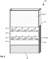
- Fig. 1 shows a device 1 for cultivating and maintaining plants in an organic or inorganic substrate for planters for producing a vegetation space in a schematic cross-sectional representation according to a first exemplary embodiment.
- the section shows a positioning element 20 and a culture pot 2, which has several irrigation and root growth openings 6.
- the openings 6 serve for irrigation and in particular as root growth openings. In this way, the plant can develop roots and in particular nutrient roots that fill the entire vegetation space 28 can.
- the culture pot 2 is suspended in the positioning element 20 with the culture pot opening 4 in the positioning element 20. In particular, the culture pot 2 is positively and/or non-positively connected to the positioning element 20 in the culture pot opening 4.
- Organic, inorganic or mixed substrate can be filled into the culture pot 2.
- the substrates have the task of giving the plant roots support and keeping the plant upright.
- the culture pot 2 has several irrigation and root growth openings 6.
- the irrigation and root growth openings 6 can be round, oval, rectangular or slot-shaped.
- the irrigation and root growth openings 6 are located on the culture pot base 19 and/or in the culture pot jacket 18 of the culture pot 2.
- the planter 8 is connected to the positioning element 20.
- the positioning element 20 has an outside 21 and an inside 23.
- the culture pot 2 has a culture pot bottom 19 and a culture pot jacket 18.
- the planter 8 has a planter bottom 9 and a planter jacket 10.
- a height distance 12 is created by the distance between the culture pot bottom 19 and the planter bottom 9 of the planter 8.
- the height distance 12 is at least 1 cm.
- a filling level 26 shows the water level of filled water or aqueous nutrient solution with a maximum height.
- the space below the positioning element 20 is divided into a water-bearing area with a water level 26 which is in the Fig. 1 corresponds to a maximum filling height, which is defined by the vessel overflow 44.
- the vessel overflow 44 offers the advantage, particularly when used outdoors or when using irrigation systems, that overwatering is excluded and the maximum filling level is not exceeded.
- An atmospheric area with the height 27 results from the water level height 26 and the distance to the positioning element 20.
- the atmosphere area 27 increases or decreases in accordance with the water level height 26.
- the filling quantity of water depends on the height of the irrigation system. and root growth openings 6, the filling material used in the culture pot 2, the distance from the bottom of the culture pot 19 to Planter base 9, the size of the planter 8 and depends on the size of the culture pot and the size of the plant.
- the positioning element 20 has at least one water level indicator opening 24.
- the water level indicator opening 24 is used to position and hold a water level indicator 14.
- the water level indicator 14 can be inserted into the water level indicator opening 24 from above.
- the water level indicator 14 extends to the planter bottom 9 of the planter 8.
- the water level indicator 14 can be designed as a water level sensor.
- the positioning element 20 is designed as a closed disk. Furthermore, the positioning element 20 is made of a corrosion-resistant metal or stainless steel. This offers the advantage that an excellent growth climate with sufficient oxygen and high humidity is formed below the positioning element 20, which leads to optimal root growth. Furthermore, the connection between the planter 8, positioning element 20 and water level indicator 14 can be made airtight. This means that the filling material used above the vegetation disk 20 remains dry, which prevents salt efflorescence or discoloration of the filling material. Ornamental gravel is usually used as the filling material, but any other visually appealing filling material can also be used. Because there is no substrate in the vegetation area 28, which is composed of the atmospheric area 27 and the water-bearing area 26, the water filling quantity is significantly increased. The vegetation space 28 extends from the planter bottom 9 of the planter 8 to the positioning element 20.
- the watering interval required for the cultivation of plants i.e. the time interval between watering necessary for optimal plant growth, is thereby significantly extended.
- the necessary watering interval could be increased by at least 5 times the watering intervals of the planting systems currently available on the market and is only shortened insignificantly over time due to a lack of mass compaction. By saving substrate, the time spent planting plant arrangements is significantly reduced.
- the culture pot 2 is not directly on the planter base 9 of the planter 8, waterlogging cannot occur. As a result of waterlogging, there is often a lack of oxygen and, as a result, root rot. Furthermore, suspended matter that is regularly released during fertilization and watering can settle on the bottom of the planter 9 of the planter 8 without any adverse effect. The irrigation and root growth openings 6 do not become clogged.
- the positioning element 20 can be designed to be semi-permeable or membrane-like and, in particular, to be permeable to air in the direction of the vegetation space 28 and impermeable to water in the opposite direction, especially impermeable to evaporation.
- the arrangement shown results in an improved growth climate in the vegetation space 28, with a corresponding level of humidity. This also results in good aeration of the roots in the vegetation area and enables good aeration of the soil in the culture pot.
- Water in particular an aqueous nutrient solution, can reach the culture pot 2 via the irrigation and root growth opening 6.
- An ideal balance of the plant's water balance is possible via the air humidity in the vegetation area 28 and via the nutrient solution.
- a first embodiment of the multifunctional device 100 for holding plants 90 is shown.
- This multifunctional device initially comprises the planter 8 and an outer container 60.
- the planter 8 is positioned in the outer container 60.
- Both the planter 8 and the outer container 60 are cylindrical.
- a water level indicator 14 can also be seen.
- the multifunctional device 100 has a power-fed functional unit 50. In this case it is a screen 70.
- the screen 70 is attached to the outer vessel 60.
- the screen 70 is attached to the surface 61 of the outer vessel 60.
- the screen 70 is designed as a curved flat screen and is arranged on the outer vessel 60 in such a way that the flat screen 70 is recessed flush with the surface 61.
- the surface 61 of the outer vessel 60 and the screen 70 thus form an almost continuous surface.
- the screen 70 therefore does not protrude from the outer vessel 60.
- a person walking past the multifunctional device 100 can therefore not get caught in anything protruding or protruding from the device 100.
- a multifunctional device 100 like this one Fig. 2 is shown, particularly suitable for positioning in company buildings or airport terminals. For example, route information can be displayed on the screen 70. Furthermore, the multifunctional device 100 can serve as an advertising space.
- the device 100 further includes a power cable 65 so that the power-fed functional unit 50 can be supplied with power from the power grid.
- Fig. 3 another multifunctional device 100 is shown. This is designed as a green wall area. Several vertically offset floors 80 are formed. In the example shown, each floor 80 includes a planter 8 with several culture pots 2 formed therein.
- the power-fed functional unit 50 is according to the embodiment of Fig. 3 again designed as a screen 70.
- the screen 70 is mounted in a vertical direction above the outer vessel 60, which in the present example is formed by the planter 8.
- the fastening device is a fastening surface.
- the multifunctional device 100 for holding plants 90 is divided into several sections.
- the outer vessel 60 is formed with the planter 8 located therein.
- a housing 85 that is separate from the planter.
- the housing 85 includes the power-fed functional unit 50. This is supplied with power via the power cable 65 shown.
- the current-fed functional unit 50 is designed on the housing 85 in the form of a lighting system 75.
- This lighting system includes an LED array.
- the lighting system 75 is fully formed in the example shown. Such lighting can serve as a traffic guidance system, for example.
- the Fig. 5 shows a multifunctional device 100, which is the multifunctional device 100 of Fig. 3 resembles.
- a power-fed functional unit 50 is designed as a screen 70, with several floors 80 with planters 8 being formed underneath.
- the device 100 has a side panel surface 66. This cladding surface extends over the entire component height of the device 100.
- a power-supplying functional unit 51 in the form of solar cells 88 is formed on the cladding surface 66.
- the multifunctional device 100 further comprises a housing 85 in which at least isolated parts of the power-supplying functional unit 51 are located. These are the batteries to be charged. The batteries can be charged by electricity generated by the solar cells 88. The charged current is used to power the current-fed functional unit 50, namely the screen 70.
- the housing 85 is designed to be waterproof. Accordingly, a watering process of the flower tiers 80 located above the housing 85 can be carried out without any problems. There can be no short circuits in connection with the electrical circuit located in the housing 85 or the battery located therein.
- the multifunctional device 100 Fig. 5 consequently includes both a power-supplied functional unit 50 and a power-supplying functional unit 51.
- FIG. 6 Another multifunctional device 100 is shown schematically.
- the outer vessel 60 includes a planter 8. Furthermore, a power-supplying functional unit 50 is shown.
- This power-supplying functional unit 51 is a power charging module 77 for electric vehicles. Also visible is a power cable 65, which is used to power the multifunctional device 100.
- the multifunctional device 100 further comprises a power-supplied functional unit 50.
- a power-supplied functional unit 50 This is designed as a payment unit 89.
- the payment unit 89 preferably includes a card reader, so that the electricity charged by an electric vehicle can be paid, for example, using an EC card or credit card or with a customer card.
- Both the current-supplied functional unit 50 and the current-supplying functional unit 51 are formed in a housing 85 that is separate from the outer vessel 60.
- a multifunctional device 100 which has a cylindrical basic shape.
- the multifunctional device 100 includes a power-supplied functional unit 50.
- This unit is designed as a radio module 78.
- the radio module 78 receives data from the water level indicator 14 located in the planter 8. With the help of the radio module 78, it is therefore possible to transmit the data from the water level indicator 14 to a control center. If the water level within the planter 8 is critical, a watering process can be initiated.
- the radio module can also be a Be a Bluetooth module or a wireless LAN module. It is therefore possible to provide a WLAN hotspot with the multifunctional device 100.
- a multifunctional device 100 is shown, which essentially has a cuboid shape.
- the planter 8 forms the outer vessel 60.
- Two culture pots 2 with plants 90 located therein are formed in the planter 8.
- the current-fed functional unit 50 namely a screen 70
- the screen 70 is mounted on the surface of the outer vessel 60.
- the multifunctional device 100 includes a further power-fed functional unit 50, namely a unit with several sockets 76.
- the sockets 76 can be used in particular to charge mobile phones.
Landscapes
- Engineering & Computer Science (AREA)
- Power Engineering (AREA)
- Transportation (AREA)
- Mechanical Engineering (AREA)
- Life Sciences & Earth Sciences (AREA)
- Environmental Sciences (AREA)
- Cultivation Receptacles Or Flower-Pots, Or Pots For Seedlings (AREA)
Claims (11)
- Dispositif multifonction (100) destiné à contenir des plantes (90) avec au moins un récipient de plante (8), comprenantun élément de positionnement (20) dans lequel au moins un pot de culture (2) qui présente une virole de pot de culture (18) et un fond de pot de culture (19) peut être inséré et fixé de telle manière que l'élément de positionnement (20) puisse être inséré dans le récipient de plante (8) conjointement avec le pot de culture (2) de telle manière qu'une zone atmosphérique (27) sensiblement étanchéifiée et un espace végétal (28) dans lequel une section inférieure du pot de culture (2) dépasse soient formés sous l'élément de positionnement (20), sachant que l'élément de positionnement (20) est constitué de telle manière que le fond de pot de culture (19) soit positionnable à une distance de hauteur (12) par rapport à un fond (9) du récipient de plante (8),caractérisé parau moins un module de chargement en courant (77) pour véhicules et au moins une unité de décompte et/ou unité de paiement (89) pour le module de chargement en courant (77).
- Dispositif multifonction (100) selon la revendication 1,
caractérisé en ce que
l'élément de positionnement (20) est fabriqué comme une tôle ou un élément surfacique, en particulier comme une tôle ou un élément surfacique sensiblement fermé destiné à renforcer une formation de condensat, et qui est formé en particulier à partir d'un matériau ayant une bonne conductivité thermique. - Dispositif multifonction (100) selon l'une des revendications 1 à 2,
caractérisé par
un récipient extérieur (60) qui est formé par le récipient de plante (8) ou dans lequel le récipient de plante (8) est positionné. - Dispositif multifonction (100) selon l'une des revendications 1 à 3,
caractérisé en ce que
une unité fonctionnelle (50) alimentée en courant comprend au moins un écran (70). - Dispositif multifonction (100) selon la revendication 4,
caractérisé en ce que
l'écran (70) est fixé sur un dispositif de fixation situé au-dessus d'un/du récipient extérieur (60) en direction verticale et/ou de manière encastrée au niveau de la surface supérieure (61) du récipient extérieur (60). - Dispositif multifonction (100) selon l'une des revendications 3 à 5, caractérisé en ce que
l'unité fonctionnelle (51) d'alimentation en courant comprend au moins une cellule photovoltaïque (88) qui est constituée sur le récipient extérieur (60) et/ou sur une face de parement (66) perpendiculaire du dispositif. - Dispositif multifonction (100) selon l'une des revendications précédentes, caractérisé en ce que
une unité fonctionnelle (51) d'alimentation en courant comprend un système d'éclairage (75). - Dispositif multifonction (100) selon l'une des revendications 3 à 7,
caractérisé par
des rouleaux constitués au niveau du fond de récipient extérieur, qui sont constitués de préférence de manière encastrable. - Dispositif multifonction (100) selon l'une des revendications précédentes, caractérisé en ce que
au moins une unité fonctionnelle alimentée en courant (50) et/ou d'alimentation en courant (51) est disposée au moins en partie dans un boîtier (85) séparé du récipient de plante (8) et constitué de manière étanche à l'eau. - Dispositif multifonction (100) selon l'une des revendications précédentes, caractérisé par
plusieurs récipients de plante (8) et/ou plusieurs pots de culture (6) qui sont disposés sur plusieurs étages (80) décalés verticalement. - Dispositif multifonction (100) selon l'une des revendications précédentes, caractérisé en ce que
une unité fonctionnelle (50) alimentée en courant comprend au moins un module radio (78).
Applications Claiming Priority (2)
| Application Number | Priority Date | Filing Date | Title |
|---|---|---|---|
| DE102017105738.2A DE102017105738A1 (de) | 2017-03-17 | 2017-03-17 | Multifunktions-Vorrichtung zum Halten von Pflanzen |
| PCT/EP2018/056476 WO2018167191A1 (fr) | 2017-03-17 | 2018-03-15 | Dispositif multifonction destiné à contenir des plantes |
Publications (3)
| Publication Number | Publication Date |
|---|---|
| EP3595433A1 EP3595433A1 (fr) | 2020-01-22 |
| EP3595433B1 true EP3595433B1 (fr) | 2023-12-20 |
| EP3595433C0 EP3595433C0 (fr) | 2023-12-20 |
Family
ID=61683795
Family Applications (1)
| Application Number | Title | Priority Date | Filing Date |
|---|---|---|---|
| EP18711548.0A Active EP3595433B1 (fr) | 2017-03-17 | 2018-03-15 | Dispositif multifonction destiné à contenir des plantes |
Country Status (3)
| Country | Link |
|---|---|
| EP (1) | EP3595433B1 (fr) |
| DE (1) | DE102017105738A1 (fr) |
| WO (1) | WO2018167191A1 (fr) |
Citations (2)
| Publication number | Priority date | Publication date | Assignee | Title |
|---|---|---|---|---|
| DE202013104271U1 (de) * | 2013-09-09 | 2013-10-02 | Wolfgang Plattner | Vorrichtung zum Halten von Hydrokulturpflanzen in einem anorganischen Substrat für Pflanzgefäße |
| WO2016203383A1 (fr) * | 2015-06-15 | 2016-12-22 | Meta System S.P.A. | Station de chargement mobile améliorée |
Family Cites Families (10)
| Publication number | Priority date | Publication date | Assignee | Title |
|---|---|---|---|---|
| GB2241860A (en) | 1990-03-12 | 1991-09-18 | Brother Ind Ltd | Automatic water-feeding cultivation apparatus |
| GB2386981A (en) * | 2002-03-28 | 2003-10-01 | Qin Gang | Combined computer system unit and plant pot |
| WO2010008813A2 (fr) | 2008-06-23 | 2010-01-21 | Reb Bieber | Système d'aération et de culture hydroponique par liquide nutritif à pompe à air |
| US20130118070A1 (en) * | 2011-11-15 | 2013-05-16 | Living Systems, Inc. | Modular system for plant growth and air purification |
| CN203261861U (zh) * | 2013-06-05 | 2013-11-06 | 袁志贤 | 一种能控制土壤温度的花盆 |
| DE202013009914U1 (de) * | 2013-11-25 | 2014-03-26 | Wolfgang Plattner | Vorrichtung zum Kultivieren und Halten von Pflanzen in einem organischen oder anorganischen Substrat für Pflanzgefäße zur Herstellung eines Vegetationsraums |
| US10104845B2 (en) * | 2015-05-31 | 2018-10-23 | EZinGrow Ltd. | Hydrophonic planter |
| DE102015117902B3 (de) * | 2015-10-21 | 2016-11-03 | Andre Frühauf | Beleuchtbarer Pflanzenbehälter |
| CN105557373B (zh) * | 2016-02-26 | 2018-05-18 | 湖州织里华宁园艺工程有限公司 | 智能型补光花盆 |
| CN105794525A (zh) * | 2016-04-13 | 2016-07-27 | 张殊文 | 一种能够调整植株生长速度的栽培容器 |
-
2017
- 2017-03-17 DE DE102017105738.2A patent/DE102017105738A1/de active Pending
-
2018
- 2018-03-15 EP EP18711548.0A patent/EP3595433B1/fr active Active
- 2018-03-15 WO PCT/EP2018/056476 patent/WO2018167191A1/fr not_active Ceased
Patent Citations (2)
| Publication number | Priority date | Publication date | Assignee | Title |
|---|---|---|---|---|
| DE202013104271U1 (de) * | 2013-09-09 | 2013-10-02 | Wolfgang Plattner | Vorrichtung zum Halten von Hydrokulturpflanzen in einem anorganischen Substrat für Pflanzgefäße |
| WO2016203383A1 (fr) * | 2015-06-15 | 2016-12-22 | Meta System S.P.A. | Station de chargement mobile améliorée |
Also Published As
| Publication number | Publication date |
|---|---|
| EP3595433A1 (fr) | 2020-01-22 |
| DE102017105738A1 (de) | 2018-09-20 |
| WO2018167191A1 (fr) | 2018-09-20 |
| EP3595433C0 (fr) | 2023-12-20 |
Similar Documents
| Publication | Publication Date | Title |
|---|---|---|
| DE2848971C2 (de) | Vorrichtung und Verfahren zur Kultivierung von Pflanzen | |
| DE102014114307B3 (de) | Pflanzenwand zur Feinstaubbindung in urbanen Bereichen | |
| DE102017114887B4 (de) | Gebäudeflächen-Pflanzsystem und Kulturtopf für Pflanzen | |
| EP3757300B1 (fr) | Système de commande du bilan hydrique et son procédé de fonctionnement | |
| DE202021100803U1 (de) | System zur Bewirtschaftung einer landwirtschaftlichen Freifläche | |
| DE3627794A1 (de) | Vorrichtung zur verfestigung der oberen bodenschicht durch ansiedlung von vegetation | |
| EP3836777B1 (fr) | Dispositif pour plantes | |
| DE3041534A1 (de) | Kapillarmatte zur wasserversorgung bepflanzer waende | |
| EP3595433B1 (fr) | Dispositif multifonction destiné à contenir des plantes | |
| DE202017001490U1 (de) | Multifunktions-Vorrichtung zum Halten von Pflanzen | |
| EP4533939A1 (fr) | Elément de façade pour mur végétalisé | |
| CN204682224U (zh) | 工厂化繁育莲草直胸跳甲设施建造 | |
| DE102022133355A1 (de) | Begrünungscontainer | |
| DE8805949U1 (de) | Bausatz zur Herstellung einer Wurzelschutzbrücke für Bäume | |
| EP0692573A1 (fr) | Système de surfaces cultivées et procédé d'alimentation en particulier d'irrigation | |
| DE2916637A1 (de) | Zier- und laermschutzsystem zum begruenen vertikaler waende | |
| DE102014016671B3 (de) | Begrünbares Bauelement | |
| CN215957519U (zh) | 一种环保型拼接式草坪 | |
| DE3627795A1 (de) | Vorrichtung zur verfestigung der oberen bodenschicht durch ansiedlung von vegetation | |
| DE3935099A1 (de) | Bauelement zur herstellung einer dachbegruenung | |
| KR200430140Y1 (ko) | 잔디보호블럭 | |
| DE3344945A1 (de) | Verfahren und vorrichtung zur erdlosen aufzucht und kultivierung von pflanzen auf schiefen ebenen, vorzugsweise im freien | |
| CN213907647U (zh) | 一种风景园林用井工程绿化墙体 | |
| DE102024113280A1 (de) | Pflanzenbehälter | |
| DE10307771B4 (de) | Hügelbeet mit Teich |
Legal Events
| Date | Code | Title | Description |
|---|---|---|---|
| STAA | Information on the status of an ep patent application or granted ep patent |
Free format text: STATUS: UNKNOWN |
|
| STAA | Information on the status of an ep patent application or granted ep patent |
Free format text: STATUS: THE INTERNATIONAL PUBLICATION HAS BEEN MADE |
|
| PUAI | Public reference made under article 153(3) epc to a published international application that has entered the european phase |
Free format text: ORIGINAL CODE: 0009012 |
|
| STAA | Information on the status of an ep patent application or granted ep patent |
Free format text: STATUS: REQUEST FOR EXAMINATION WAS MADE |
|
| 17P | Request for examination filed |
Effective date: 20191015 |
|
| AK | Designated contracting states |
Kind code of ref document: A1 Designated state(s): AL AT BE BG CH CY CZ DE DK EE ES FI FR GB GR HR HU IE IS IT LI LT LU LV MC MK MT NL NO PL PT RO RS SE SI SK SM TR |
|
| AX | Request for extension of the european patent |
Extension state: BA ME |
|
| DAV | Request for validation of the european patent (deleted) | ||
| DAX | Request for extension of the european patent (deleted) | ||
| STAA | Information on the status of an ep patent application or granted ep patent |
Free format text: STATUS: EXAMINATION IS IN PROGRESS |
|
| 17Q | First examination report despatched |
Effective date: 20220926 |
|
| REG | Reference to a national code |
Ref country code: DE Free format text: PREVIOUS MAIN CLASS: A01G0009020000 Ipc: B60L0053300000 Ref country code: DE Ref legal event code: R079 Ref document number: 502018013836 Country of ref document: DE Free format text: PREVIOUS MAIN CLASS: A01G0009020000 Ipc: B60L0053300000 |
|
| RIC1 | Information provided on ipc code assigned before grant |
Ipc: B60L 53/66 20190101ALI20230605BHEP Ipc: B60L 53/51 20190101ALI20230605BHEP Ipc: B60L 53/53 20190101ALI20230605BHEP Ipc: A01G 9/02 20180101ALI20230605BHEP Ipc: A01G 31/02 20060101ALI20230605BHEP Ipc: B60L 53/30 20190101AFI20230605BHEP |
|
| GRAP | Despatch of communication of intention to grant a patent |
Free format text: ORIGINAL CODE: EPIDOSNIGR1 |
|
| STAA | Information on the status of an ep patent application or granted ep patent |
Free format text: STATUS: GRANT OF PATENT IS INTENDED |
|
| INTG | Intention to grant announced |
Effective date: 20230718 |
|
| GRAS | Grant fee paid |
Free format text: ORIGINAL CODE: EPIDOSNIGR3 |
|
| GRAA | (expected) grant |
Free format text: ORIGINAL CODE: 0009210 |
|
| STAA | Information on the status of an ep patent application or granted ep patent |
Free format text: STATUS: THE PATENT HAS BEEN GRANTED |
|
| AK | Designated contracting states |
Kind code of ref document: B1 Designated state(s): AL AT BE BG CH CY CZ DE DK EE ES FI FR GB GR HR HU IE IS IT LI LT LU LV MC MK MT NL NO PL PT RO RS SE SI SK SM TR |
|
| REG | Reference to a national code |
Ref country code: GB Ref legal event code: FG4D Free format text: NOT ENGLISH |
|
| REG | Reference to a national code |
Ref country code: DE Ref legal event code: R096 Ref document number: 502018013836 Country of ref document: DE |
|
| REG | Reference to a national code |
Ref country code: CH Ref legal event code: EP |
|
| REG | Reference to a national code |
Ref country code: IE Ref legal event code: FG4D Free format text: LANGUAGE OF EP DOCUMENT: GERMAN |
|
| U01 | Request for unitary effect filed |
Effective date: 20240115 |
|
| U07 | Unitary effect registered |
Designated state(s): AT BE BG DE DK EE FI FR IT LT LU LV MT NL PT SE SI Effective date: 20240123 |
|
| U20 | Renewal fee for the european patent with unitary effect paid |
Year of fee payment: 7 Effective date: 20240228 |
|
| PG25 | Lapsed in a contracting state [announced via postgrant information from national office to epo] |
Ref country code: GR Free format text: LAPSE BECAUSE OF FAILURE TO SUBMIT A TRANSLATION OF THE DESCRIPTION OR TO PAY THE FEE WITHIN THE PRESCRIBED TIME-LIMIT Effective date: 20240321 |
|
| PG25 | Lapsed in a contracting state [announced via postgrant information from national office to epo] |
Ref country code: ES Free format text: LAPSE BECAUSE OF FAILURE TO SUBMIT A TRANSLATION OF THE DESCRIPTION OR TO PAY THE FEE WITHIN THE PRESCRIBED TIME-LIMIT Effective date: 20231220 |
|
| PG25 | Lapsed in a contracting state [announced via postgrant information from national office to epo] |
Ref country code: GR Free format text: LAPSE BECAUSE OF FAILURE TO SUBMIT A TRANSLATION OF THE DESCRIPTION OR TO PAY THE FEE WITHIN THE PRESCRIBED TIME-LIMIT Effective date: 20240321 Ref country code: ES Free format text: LAPSE BECAUSE OF FAILURE TO SUBMIT A TRANSLATION OF THE DESCRIPTION OR TO PAY THE FEE WITHIN THE PRESCRIBED TIME-LIMIT Effective date: 20231220 |
|
| PG25 | Lapsed in a contracting state [announced via postgrant information from national office to epo] |
Ref country code: RS Free format text: LAPSE BECAUSE OF FAILURE TO SUBMIT A TRANSLATION OF THE DESCRIPTION OR TO PAY THE FEE WITHIN THE PRESCRIBED TIME-LIMIT Effective date: 20231220 Ref country code: NO Free format text: LAPSE BECAUSE OF FAILURE TO SUBMIT A TRANSLATION OF THE DESCRIPTION OR TO PAY THE FEE WITHIN THE PRESCRIBED TIME-LIMIT Effective date: 20240320 Ref country code: HR Free format text: LAPSE BECAUSE OF FAILURE TO SUBMIT A TRANSLATION OF THE DESCRIPTION OR TO PAY THE FEE WITHIN THE PRESCRIBED TIME-LIMIT Effective date: 20231220 |
|
| PG25 | Lapsed in a contracting state [announced via postgrant information from national office to epo] |
Ref country code: IS Free format text: LAPSE BECAUSE OF FAILURE TO SUBMIT A TRANSLATION OF THE DESCRIPTION OR TO PAY THE FEE WITHIN THE PRESCRIBED TIME-LIMIT Effective date: 20240420 |
|
| PG25 | Lapsed in a contracting state [announced via postgrant information from national office to epo] |
Ref country code: CZ Free format text: LAPSE BECAUSE OF FAILURE TO SUBMIT A TRANSLATION OF THE DESCRIPTION OR TO PAY THE FEE WITHIN THE PRESCRIBED TIME-LIMIT Effective date: 20231220 |
|
| PG25 | Lapsed in a contracting state [announced via postgrant information from national office to epo] |
Ref country code: SK Free format text: LAPSE BECAUSE OF FAILURE TO SUBMIT A TRANSLATION OF THE DESCRIPTION OR TO PAY THE FEE WITHIN THE PRESCRIBED TIME-LIMIT Effective date: 20231220 |
|
| PG25 | Lapsed in a contracting state [announced via postgrant information from national office to epo] |
Ref country code: SM Free format text: LAPSE BECAUSE OF FAILURE TO SUBMIT A TRANSLATION OF THE DESCRIPTION OR TO PAY THE FEE WITHIN THE PRESCRIBED TIME-LIMIT Effective date: 20231220 Ref country code: SK Free format text: LAPSE BECAUSE OF FAILURE TO SUBMIT A TRANSLATION OF THE DESCRIPTION OR TO PAY THE FEE WITHIN THE PRESCRIBED TIME-LIMIT Effective date: 20231220 Ref country code: RO Free format text: LAPSE BECAUSE OF FAILURE TO SUBMIT A TRANSLATION OF THE DESCRIPTION OR TO PAY THE FEE WITHIN THE PRESCRIBED TIME-LIMIT Effective date: 20231220 Ref country code: IS Free format text: LAPSE BECAUSE OF FAILURE TO SUBMIT A TRANSLATION OF THE DESCRIPTION OR TO PAY THE FEE WITHIN THE PRESCRIBED TIME-LIMIT Effective date: 20240420 Ref country code: CZ Free format text: LAPSE BECAUSE OF FAILURE TO SUBMIT A TRANSLATION OF THE DESCRIPTION OR TO PAY THE FEE WITHIN THE PRESCRIBED TIME-LIMIT Effective date: 20231220 |
|
| PG25 | Lapsed in a contracting state [announced via postgrant information from national office to epo] |
Ref country code: PL Free format text: LAPSE BECAUSE OF FAILURE TO SUBMIT A TRANSLATION OF THE DESCRIPTION OR TO PAY THE FEE WITHIN THE PRESCRIBED TIME-LIMIT Effective date: 20231220 |
|
| PG25 | Lapsed in a contracting state [announced via postgrant information from national office to epo] |
Ref country code: PL Free format text: LAPSE BECAUSE OF FAILURE TO SUBMIT A TRANSLATION OF THE DESCRIPTION OR TO PAY THE FEE WITHIN THE PRESCRIBED TIME-LIMIT Effective date: 20231220 |
|
| REG | Reference to a national code |
Ref country code: DE Ref legal event code: R097 Ref document number: 502018013836 Country of ref document: DE |
|
| PLBE | No opposition filed within time limit |
Free format text: ORIGINAL CODE: 0009261 |
|
| STAA | Information on the status of an ep patent application or granted ep patent |
Free format text: STATUS: NO OPPOSITION FILED WITHIN TIME LIMIT |
|
| REG | Reference to a national code |
Ref country code: CH Ref legal event code: PL |
|
| PG25 | Lapsed in a contracting state [announced via postgrant information from national office to epo] |
Ref country code: MC Free format text: LAPSE BECAUSE OF FAILURE TO SUBMIT A TRANSLATION OF THE DESCRIPTION OR TO PAY THE FEE WITHIN THE PRESCRIBED TIME-LIMIT Effective date: 20231220 |
|
| 26N | No opposition filed |
Effective date: 20240923 |
|
| GBPC | Gb: european patent ceased through non-payment of renewal fee |
Effective date: 20240320 |
|
| PG25 | Lapsed in a contracting state [announced via postgrant information from national office to epo] |
Ref country code: MC Free format text: LAPSE BECAUSE OF FAILURE TO SUBMIT A TRANSLATION OF THE DESCRIPTION OR TO PAY THE FEE WITHIN THE PRESCRIBED TIME-LIMIT Effective date: 20231220 |
|
| PG25 | Lapsed in a contracting state [announced via postgrant information from national office to epo] |
Ref country code: GB Free format text: LAPSE BECAUSE OF NON-PAYMENT OF DUE FEES Effective date: 20240320 |
|
| PG25 | Lapsed in a contracting state [announced via postgrant information from national office to epo] |
Ref country code: IE Free format text: LAPSE BECAUSE OF NON-PAYMENT OF DUE FEES Effective date: 20240315 |
|
| PG25 | Lapsed in a contracting state [announced via postgrant information from national office to epo] |
Ref country code: IE Free format text: LAPSE BECAUSE OF NON-PAYMENT OF DUE FEES Effective date: 20240315 Ref country code: GB Free format text: LAPSE BECAUSE OF NON-PAYMENT OF DUE FEES Effective date: 20240320 Ref country code: CH Free format text: LAPSE BECAUSE OF NON-PAYMENT OF DUE FEES Effective date: 20240331 |
|
| U20 | Renewal fee for the european patent with unitary effect paid |
Year of fee payment: 8 Effective date: 20250331 |
|
| PG25 | Lapsed in a contracting state [announced via postgrant information from national office to epo] |
Ref country code: CY Free format text: LAPSE BECAUSE OF FAILURE TO SUBMIT A TRANSLATION OF THE DESCRIPTION OR TO PAY THE FEE WITHIN THE PRESCRIBED TIME-LIMIT; INVALID AB INITIO Effective date: 20180315 |
|
| PG25 | Lapsed in a contracting state [announced via postgrant information from national office to epo] |
Ref country code: HU Free format text: LAPSE BECAUSE OF FAILURE TO SUBMIT A TRANSLATION OF THE DESCRIPTION OR TO PAY THE FEE WITHIN THE PRESCRIBED TIME-LIMIT; INVALID AB INITIO Effective date: 20180315 |
|
| PG25 | Lapsed in a contracting state [announced via postgrant information from national office to epo] |
Ref country code: TR Free format text: LAPSE BECAUSE OF FAILURE TO SUBMIT A TRANSLATION OF THE DESCRIPTION OR TO PAY THE FEE WITHIN THE PRESCRIBED TIME-LIMIT Effective date: 20231220 |