EP3596814B1 - Umrichteranordnung mit brandmeldeanlage - Google Patents
Umrichteranordnung mit brandmeldeanlage Download PDFInfo
- Publication number
- EP3596814B1 EP3596814B1 EP17807767.3A EP17807767A EP3596814B1 EP 3596814 B1 EP3596814 B1 EP 3596814B1 EP 17807767 A EP17807767 A EP 17807767A EP 3596814 B1 EP3596814 B1 EP 3596814B1
- Authority
- EP
- European Patent Office
- Prior art keywords
- aperture
- light signal
- optical waveguide
- converter arrangement
- aperture element
- Prior art date
- Legal status (The legal status is an assumption and is not a legal conclusion. Google has not performed a legal analysis and makes no representation as to the accuracy of the status listed.)
- Active
Links
- 230000003287 optical effect Effects 0.000 claims description 49
- 238000000034 method Methods 0.000 claims description 11
- 239000004065 semiconductor Substances 0.000 claims description 11
- 238000011156 evaluation Methods 0.000 claims description 10
- 238000012544 monitoring process Methods 0.000 claims description 10
- 230000009467 reduction Effects 0.000 claims description 9
- 230000008859 change Effects 0.000 claims description 8
- 238000005259 measurement Methods 0.000 claims description 8
- 230000000694 effects Effects 0.000 claims description 3
- 230000005540 biological transmission Effects 0.000 description 7
- 230000008901 benefit Effects 0.000 description 3
- 239000003990 capacitor Substances 0.000 description 2
- 238000001514 detection method Methods 0.000 description 2
- 239000013307 optical fiber Substances 0.000 description 2
- 230000009471 action Effects 0.000 description 1
- 238000009529 body temperature measurement Methods 0.000 description 1
- 238000006243 chemical reaction Methods 0.000 description 1
- 230000008878 coupling Effects 0.000 description 1
- 238000010168 coupling process Methods 0.000 description 1
- 238000005859 coupling reaction Methods 0.000 description 1
- 238000013461 design Methods 0.000 description 1
- 238000011161 development Methods 0.000 description 1
- 238000005516 engineering process Methods 0.000 description 1
- 230000000977 initiatory effect Effects 0.000 description 1
- 230000001902 propagating effect Effects 0.000 description 1
- 230000006641 stabilisation Effects 0.000 description 1
- 238000011105 stabilization Methods 0.000 description 1
- 230000002123 temporal effect Effects 0.000 description 1
- 230000001960 triggered effect Effects 0.000 description 1
Images


Classifications
-
- H—ELECTRICITY
- H02—GENERATION; CONVERSION OR DISTRIBUTION OF ELECTRIC POWER
- H02M—APPARATUS FOR CONVERSION BETWEEN AC AND AC, BETWEEN AC AND DC, OR BETWEEN DC AND DC, AND FOR USE WITH MAINS OR SIMILAR POWER SUPPLY SYSTEMS; CONVERSION OF DC OR AC INPUT POWER INTO SURGE OUTPUT POWER; CONTROL OR REGULATION THEREOF
- H02M1/00—Details of apparatus for conversion
- H02M1/32—Means for protecting converters other than automatic disconnection
-
- G—PHYSICS
- G01—MEASURING; TESTING
- G01K—MEASURING TEMPERATURE; MEASURING QUANTITY OF HEAT; THERMALLY-SENSITIVE ELEMENTS NOT OTHERWISE PROVIDED FOR
- G01K11/00—Measuring temperature based upon physical or chemical changes not covered by groups G01K3/00, G01K5/00, G01K7/00 or G01K9/00
- G01K11/32—Measuring temperature based upon physical or chemical changes not covered by groups G01K3/00, G01K5/00, G01K7/00 or G01K9/00 using changes in transmittance, scattering or luminescence in optical fibres
- G01K11/3206—Measuring temperature based upon physical or chemical changes not covered by groups G01K3/00, G01K5/00, G01K7/00 or G01K9/00 using changes in transmittance, scattering or luminescence in optical fibres at discrete locations in the fibre, e.g. using Bragg scattering
-
- G—PHYSICS
- G01—MEASURING; TESTING
- G01K—MEASURING TEMPERATURE; MEASURING QUANTITY OF HEAT; THERMALLY-SENSITIVE ELEMENTS NOT OTHERWISE PROVIDED FOR
- G01K5/00—Measuring temperature based on the expansion or contraction of a material
- G01K5/48—Measuring temperature based on the expansion or contraction of a material the material being a solid
- G01K5/56—Measuring temperature based on the expansion or contraction of a material the material being a solid constrained so that expansion or contraction causes a deformation of the solid
- G01K5/62—Measuring temperature based on the expansion or contraction of a material the material being a solid constrained so that expansion or contraction causes a deformation of the solid the solid body being formed of compounded strips or plates, e.g. bimetallic strip
-
- H—ELECTRICITY
- H02—GENERATION; CONVERSION OR DISTRIBUTION OF ELECTRIC POWER
- H02M—APPARATUS FOR CONVERSION BETWEEN AC AND AC, BETWEEN AC AND DC, OR BETWEEN DC AND DC, AND FOR USE WITH MAINS OR SIMILAR POWER SUPPLY SYSTEMS; CONVERSION OF DC OR AC INPUT POWER INTO SURGE OUTPUT POWER; CONTROL OR REGULATION THEREOF
- H02M1/00—Details of apparatus for conversion
- H02M1/32—Means for protecting converters other than automatic disconnection
- H02M1/327—Means for protecting converters other than automatic disconnection against abnormal temperatures
Definitions
- the invention relates to a converter arrangement with a multiplicity of electrically connected switching modules, each of which has semiconductor switches, as well as with a fire alarm system for fire monitoring of the converter arrangement.
- a converter arrangement with switching modules electrically connected in series, which include semiconductor switches connected in a half-bridge circuit or a full-bridge circuit, is for example from FIG WO 2016/155850 A1 known.
- the converter described there is known as a modular multi-stage converter (MMC).
- MMC modular multi-stage converter
- the MMC is particularly characterized by its modular design. It comprises converter arms which each extend between an AC voltage connection and one of two DC voltage poles of the MMC.
- the converter arms of the MMC each have a series connection of two-pole switching modules, each switching module comprising semiconductor switches that can be switched on and off and an energy store, preferably in the form of a converter capacitor.
- Each of the switching modules can be controlled individually by means of a control device.
- a voltage drop across the converter arm is equal to the sum of the voltages dropped across the associated switching modules.
- a particularly advantageous, step-shaped converter voltage can be generated by means of the MMC.
- the switching modules are usually designed as half-bridge circuits or as full-bridge circuits.
- the switching module in half-bridge circuit has two semiconductor switches that can be switched off and the energy store, the semiconductor switches being connected to the energy store in such a way that an energy store voltage dropping across the energy store or a zero voltage can be generated at the output terminals of the switch module.
- Converter arrangements of this type are usually used for power conversion, for example in high-voltage direct current transmission, as well as for reactive power compensation or stabilization of alternating voltage networks used. In such cases, the converter arm is arranged, for example, between two AC voltage connections of the converter.
- the fire alarm system has the task of detecting a fire which has occurred due to a fault in the converter arrangement and which can be dangerous for the functioning of the converter arrangement. In such a case, the fire alarm system reports a corresponding error signal to a higher-level point that is suitable for initiating a countermeasure. Due to the complex structure of the above-mentioned converter arrangement, fire monitoring is usually costly.
- the FR 2 616 905 A1 describes the use of optical fibers for temperature measurement.
- the object of the invention is to propose a converter arrangement of the above type which has inexpensive and reliable fire monitoring.
- the object is achieved in a converter arrangement of the appropriate type in that the fire alarm system comprises at least one optical waveguide which has a screen element at several predetermined, spaced-apart locations, each screen element reducing a light intensity of a light signal passing the screen element when the temperature rises on the screen element.
- the invention is based on the knowledge that the heat generated in a potential fire leads to a Fire detection can be used.
- This development of heat or a corresponding change in temperature is used here to reduce the light intensity of a light that propagates in the optical waveguide.
- This reduction in the light intensity is achieved by means of several temperature-sensitive diaphragm elements which are arranged in the optical waveguide.
- the optical waveguide can be arranged within the converter arrangement in such a way that it runs in the vicinity of potential sources of fire or points of fire.
- the screen elements are arranged at predetermined points in the optical waveguide, so that a light or light signal propagating in the optical waveguide passes the screen elements.
- the screen elements are suitably arranged in the vicinity of the potential fire points.
- the fire alarm system can comprise a suitable evaluation device, for example.
- the fire alarm system can be configured or calibrated in such a way that, for example, a temperature change of more than 50 K at one of the screen elements corresponds to a reduction in the light intensity, which leads to a warning signal being triggered.
- cover elements Components that are already known and commercially available can be used as cover elements. These are known, for example, from photo technology.
- the screen elements can be used in a simple manner in generally known, customary optical waveguides at the predetermined locations. For these reasons, the proposed fire alarm system of the converter arrangement according to the invention is advantageously inexpensive. Due to the simple principle of action, it is also particularly reliable in operation.
- An additional advantage of the solution according to the invention is the security of the fire alarm system against electromagnetic coupling.
- At least one of the screen elements preferably comprises a screen inserted into the optical waveguide.
- the aperture can open or close its aperture.
- a reduction in the diaphragm opening reduces the light intensity of a light signal passing through the diaphragm. In this way, a particularly simple structure of the screen element is provided.
- An opening time or closing time of the diaphragm can be between 0.5 s and 2 s, for example.
- the screen element comprises a bimetal element.
- the bimetal element has the property that it is temperature sensitive.
- the bimetal element can change its shape as a function of the temperature.
- the bimetal element is expediently connected to the diaphragm, so that a change in temperature causes a reduction in the diaphragm opening.
- the fire alarm system comprises a transmission device for feeding a light signal into the optical waveguide.
- the transmitting device can, for example, feed a laser light signal into the optical waveguide. It can also be implemented as a light emitting diode or the like.
- the transmission device can be set up to feed a light signal, which is composed of individual light pulses, into the optical waveguide.
- the light signal is preferably a protocol signal with a varying light intensity.
- the protocol signal can, for example, be a predetermined sequence of individual light pulses.
- the protocol signal allows improved detection of the fire location.
- the information (for example binary) contained in the protocol signal can be used to prevent false alarms avoid or at least minimize the fire alarm system.
- the protocol signal can comprise information formatted by means of a Barker code, for example.
- the fire alarm system comprises a measuring device for detecting an output light signal at an output of the optical waveguide and / or an evaluation device for evaluating the output light signal.
- the output of the optical waveguide can be arranged at any suitable location on the optical waveguide, in particular at the end of the optical waveguide opposite the transmitting device.
- the measuring device which can be connected on the output side to the evaluation device, is expediently located at the output.
- the measuring device can for example comprise a photodiode and / or suitable amplifiers.
- the evaluation device suitably comprises corresponding evaluation electronics that analyze the detected signal.
- At least one of the, preferably all, panel elements is suitably in thermal contact with a housing of one or more of the switching modules.
- the section of the optical waveguide containing the diaphragm element can be mechanically fastened to the housing or at least arranged adjacent to it.
- the switching modules can be identified as potential fire locations due to the high currents that flow through the switching modules. An arrangement of the screen elements in direct contact with the housings of the switching modules is therefore particularly suitable for further increasing the reliability of the fire alarm system.
- the screen elements are reflective.
- the transmission device for feeding the light signal into the optical waveguide is preferably set up to detect and evaluate light reflected by one of the diaphragm elements.
- the transmitter device is particularly preferably also set up to send a pulsed light signal into the optical waveguide feed, wherein a distance measurement can be carried out by means of a transit time measurement of the pulsed light signal.
- the fault location for example in the event of a fire, can advantageously be determined. If, for example, there is a temperature increase on one of the switch modules, the corresponding panel element closes. This screen element thus reflects part of the light passing through. This can be used to determine the location of the fault.
- the procedure can be as follows: If a reduction in the light intensity is detected at the output of one of the optical waveguides, the transmission device switches to pulse operation.
- the pulsed light signal is fed into the relevant optical waveguide.
- the transit time of the light pulses of the pulsed light signal to the point of reflection on the reflective screen element and thus the location of the fault can thus be determined. In this way it is possible that only one optical fiber has to be installed to monitor the entire converter arrangement.
- the invention further relates to a method for fire monitoring of a converter arrangement with a plurality of electrically connected switching modules, each of which has semiconductor switches which are arranged in a housing.
- the object of the invention is to provide such a method that is as inexpensive and reliable as possible.
- the object is achieved according to the invention by such a method in which a light signal is fed into an optical waveguide, a light intensity of the light signal when passing a screen element that is inserted into the optical waveguide and is in thermal contact with one of the housing of the switching modules, depending on a Temperature change at the diaphragm element is reduced, an output light signal is detected at an output of the optical waveguide, and if the output light signal is a predetermined one Trigger condition fulfilled, a warning signal is sent to a warning signal receiver.
- a pulsed light signal is fed into the optical waveguide and a distance measurement is carried out to determine the distance to this diaphragm element by means of a transit time measurement of the pulsed light signal reflected on a reflective diaphragm element.
- FIG. 1 a converter arrangement 1 is shown.
- the converter arrangement 1 comprises converter arms which are each arranged between a DC voltage connection and an AC voltage connection.
- the converter arrangement 1 For the sake of clarity, only one converter arm 2 is shown figuratively, which comprises a series connection of two-pole switching modules 3.
- the converter arm 2 extends between an AC voltage connection 4 and a DC voltage busbar 5.
- Each of the switching modules 3 comprises a housing 3a in which semiconductor switches connected in a half-bridge circuit are arranged.
- each of the switching modules 3 is assigned a capacitor 6 to which the switching module 3 is electrically connected.
- the switching modules 3 are carried by a support structure 7, which is also referred to as a tower.
- the number of switching modules 3 in the converter arm 2 can be up to several hundred.
- the converter arrangement 1 further comprises a fire alarm system 8.
- the fire alarm system has a transmission device 9, four optical waveguides 10a-10d and a measuring and evaluation device 11.
- the first optical waveguide 10a has diaphragm elements 12-15 built into the optical waveguide 10a at predetermined points.
- the fourth optical waveguide 10d also has diaphragm elements 16-19 which are inserted into the optical waveguide 10d at points provided for this purpose.
- the remaining optical waveguides 10b and 10c also have diaphragm elements, which are shown in FIG Figure 1 are not provided with corresponding reference numerals for reasons of clarity. All panel elements of the converter arrangement 1 are constructed in the same way, but this does not generally have to be the case.
- the diaphragm elements 12-19 include a diaphragm and a bimetal element which are connected to one another in such a way that in the event of a predetermined temperature change the bimetal element interacts with the diaphragm in such a way that a diaphragm opening of the diaphragm is reduced.
- the cover elements 12-19 are in thermal contact with the housings 3a of the switching modules 3. In this way, a fire that has occurred in or on the switching module 3 can be particularly reliably detected.
- the method for fire monitoring is to be explained below in connection with the first optical waveguide 10a.
- the method is carried out accordingly using the remaining optical waveguides 10b-d.
- a light signal is fed into the optical waveguide 10a, the light signal having a predetermined signal length and a predetermined signal curve over time.
- the light signal runs through the optical waveguide 10a and passes the diaphragm elements 12-15.
- a light intensity of the light signal is changed as a function of a temperature on the screen elements in the manner described above.
- the light signal is a protocol signal, its temporal course is changed.
- the measuring and evaluation device 11 by means of which an output signal is detected, is arranged at an output 22 of the first optical waveguide 10a.
- the output signal corresponds to the changed light signal at the output 22.
- the output signal is analyzed. If the output signal corresponds to a predetermined condition stored in the evaluation device 11, then a message signal is then sent to a higher-level central monitoring unit.
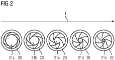
- Figure 2 shows different states of a screen 20 of one of the screen elements 12-19 as a function of the temperature.
- a temperature rise is indicated by an arrow T. It is in Figure 2 It can be seen that at lower temperatures a diaphragm opening 21a of the diaphragm 20 is larger than the diaphragm opening 21e of the diaphragm 20 at higher temperatures.
- the intermediate states of the diaphragm 20 with respect to the diaphragm openings are correspondingly identified with the reference symbols 21b-d. It can be seen that due to the reduced diaphragm opening 21e, the light intensity of a light signal passing through the diaphragm 20 or the diaphragm opening 21e is reduced.
- FIG. 3 shows a converter arrangement 30 with a plurality of switching modules 31.
- the converter arrangement comprises a fire alarm system with an optical waveguide 32 and screen elements 33.
- a transmitting device 34 comprises an emitter 35 and a receiver 36.
- a light signal can be fed into the optical waveguide 32 by means of the emitter 35.
- the intensity of the light signal can be measured by means of a receiver 37 at an output 38 of the optical waveguide 32.
- a lightning symbol 39 denotes in Figure 3 the location of a fire in the converter arrangement 30.
- the closest shutter 33 closes at least partially, so that the intensity of the light signal fed in is greater than the intensity measured at the output 38, which is shown in FIG Figure 3 is indicated schematically by the arrows 40 and 41, respectively.
- the diaphragm elements 33 are designed in such a way that part of the light of the light signal is reflected on the relevant diaphragm 33, which is indicated by means of an arrow 42.
- a corresponding signal is sent to the transmitting device 34.
- the transmitting device 34 then feeds a pulsed light signal into the optical waveguide 32.
- the pulsed light signals that are at least partially reflected on the diaphragm element 33 are detected by the receiver 36, their transit time being measured. In this way, the distance between the transmitting device 32 and the fire can be determined.
Landscapes
- Physics & Mathematics (AREA)
- General Physics & Mathematics (AREA)
- Engineering & Computer Science (AREA)
- Power Engineering (AREA)
- Fire-Detection Mechanisms (AREA)
Description
- Die Erfindung betrifft eine Umrichteranordnung mit einer Vielzahl elektrisch verbundener Schaltmodule, die jeweils Halbleiterschalter aufweisen, sowie mit einer Brandmeldeanlage zur Brandüberwachung der Umrichteranordnung.
- Eine Umrichteranordnung mit elektrisch in Reihe verbundenen Schaltmodulen, die in einer Halbbrückenschaltung bzw. einer Vollbrückenschaltung verbundene Halbleiterschalter umfassen, ist beispielsweise aus der
WO 2016/155850 A1 bekannt. Der dort beschriebene Umrichter wird als modularer Mehrstufenumrichter (MMC) bezeichnet. Der MMC zeichnet sich insbesondere durch eine modulare Bauweise aus. Er umfasst Umrichterarme, die sich jeweils zwischen einem Wechselspannungsanschluss und einem von zwei Gleichspannungspolen des MMC erstrecken. Die Umrichterarme des MMC weisen jeweils eine Reihenschaltung zweipoliger Schaltmodule auf, wobei jedes Schaltmodul ein- und abschaltbare Halbleiterschalter sowie einen Energiespeicher, bevorzugt in Form eines Umrichterkondensators, umfasst. Jedes der Schaltmodule ist mittels einer Ansteuereinrichtung einzeln ansteuerbar. Eine an dem Umrichterarm abfallende Spannung ist gleich der Summe von Spannungen, die an den zugehörigen Schaltmodulen abfallen. Mittels des MMC ist eine besonders vorteilhafte, stufenförmige Konverterspannung erzeugbar. Die Schaltmodule sind meist als Halbbrückenschaltungen oder als Vollbrückenschaltungen ausgebildet. Das Schaltmodul in Halbbrückenschaltung weist zwei abschaltbare Halbleiterschalter und den Energiespeicher auf, wobei die Halbleiterschalter so mit dem Energiespeicher verschaltet sind, dass an den Ausgangsklemmen des Schaltmoduls eine an dem Energiespeicher abfallende Energiespeicherspannung oder eine Nullspannung erzeugbar ist. Umrichteranordnungen dieser Art werden üblicherweise zur Stromumwandlung, beispielsweise in der Hochspannungsgleichstromübertragung, als auch zur Blindleistungskompensation bzw. Stabilisierung von Wechselspannungsnetzen eingesetzt. In solchen Fällen ist der Umrichterarm beispielsweise zwischen zwei Wechselspannungsanschlüssen des Umrichters angeordnet. - Zur Brandüberwachung einer solchen Umrichteranordnung ist es darüber hinaus bekannt, eine Brandmeldeanlage vorzusehen. Die Brandmeldeanlage hat die Aufgabe, einen aufgrund eines Fehlers in der Umrichteranordnung aufgetretenen Brand, der für die Funktionsweise der Umrichteranordnung gefährlich sein kann, zu erkennen. In einem solchen Fall meldet die Brandmeldeanlage ein entsprechendes Fehlersignal an eine übergeordnete Stelle, die zur Einleitung einer Gegenmaßnahme geeignet ist. Aufgrund des komplexen Aufbaus der oben genannten Umrichteranordnung ist eine Brandüberwachung meist kostenintensiv.
- Aus der
DE 10 2014 212348 A1 ist das Problem bekannt, eine Temperaturüberwachung mehrerer Halbleitermodule vorzusehen, ohne für jedes zu überwachende Halbleitermodul einen Temperatursensor einsetzen zu müssen. - Die
FR 2 616 905 A1 - Die Aufgabe der Erfindung ist es, eine Umrichteranordnung der obigen Art vorzuschlagen, die über eine kostengünstige und zuverlässige Brandüberwachung verfügt.
- Die Aufgabe wird bei einer artgemäßen Umrichteranordnung erfindungsgemäß dadurch gelöst, dass die Brandmeldeanlage wenigstens einen Lichtwellenleiter umfasst, der an mehreren vorbestimmten, voneinander beabstandeten Stellen jeweils ein Blendeelement aufweist, wobei jedes Blendeelement bei einem Temperaturanstieg am Blendeelement eine Lichtintensität eines das Blendeelement passierenden Lichtsignals reduziert.
- Der Erfindung liegt die Erkenntnis zugrunde, dass die bei einem potenziellen Brand erzeugte Hitzeentwicklung zu einer Branddetektion genutzt werden kann. Diese Hitzeentwicklung beziehungsweise eine entsprechende Temperaturänderung wird hierbei dazu genutzt, eine Lichtintensität eines Lichts zu reduzieren, das sich im Lichtwellenleiter ausbreitet. Diese Reduktion der Lichtintensität wird mittels mehrerer temperaturempfindlicher Blendeelemente erreicht, die in dem Lichtwellenleiter angeordnet sind. Insbesondere kann der Lichtwellenleiter innerhalb der Umrichteranordnung derart angeordnet sein, dass er in der Nähe potenzieller Brandherde bzw. Brandstellen verläuft. An vorbestimmten Stellen im Lichtwellenleiter sind die Blendeelemente angeordnet, so dass ein sich im Lichtwellenleiter ausbreitendes Licht bzw. Lichtsignal die Blendeelemente passiert. Die Blendeelemente sind geeigneterweise in der Nähe der potenziellen Brandstellen angeordnet.
- Entsteht an einem der Orte innerhalb der Umrichteranordnung ein Brand, so erhöht sich die Temperatur am Brandort. Diese Temperaturänderung bewirkt zweckmäßigerweise, dass die Lichtintensität des Lichtsignals, das dasjenige Blendeelement passiert, das in der Nähe oder am Brandort angeordnet ist, reduziert wird. Diese Reduktion kann als ein Hinweis auf den Brand gewertet werden. Dazu kann die Brandmeldeanlage beispielsweise eine geeignete Auswertevorrichtung umfassen.
- Die Brandmeldeanlage kann derart konfiguriert bzw. kalibriert sein, dass beispielsweise eine Temperaturänderung um mehr als 50 K an einem der Blendeelemente einer Reduktion der Lichtintensität entspricht, die zu einer Auslösung eines Warnsignals führt.
- Als Blendeelemente können bereits bekannte und im Handel erhältliche Bauteile verwendet werden. Diese sind beispielsweise aus der Fototechnik bekannt. Die Blendeelemente können auf einfache Weise in allgemein bekannte, gewöhnliche Lichtwellenleiter an den vorbestimmten Stellen eingesetzt werden. Aus diesen Gründen ist die vorgeschlagene Brandmeldeanlage der erfindungsgemäßen Umrichteranordnung vorteilhaft kostengünstig. Aufgrund des einfachen Wirkungsprinzips ist sie zudem besonders zuverlässig im Betrieb. Ein zusätzlicher Vorteil der erfindungsgemäßen Lösung ist die Sicherheit der Brandmeldeanlage gegen elektromagnetische Einkopplung.
- Vorzugsweise umfasst wenigstens eines der Blendeelemente eine in den Lichtwellenleiter eingesetzte Blende. Die Blende kann ihre Blendenöffnung öffnen bzw. schließen. Eine Verkleinerung der Blendenöffnung reduziert die Lichtintensität eines die Blende passierenden Lichtsignals. Auf diese Weise ist ein besonders einfacher Aufbau des Blendeelements bereitgestellt. Eine Öffnungszeit bzw. Schließzeit der Blende kann beispielsweise zwischen 0,5 s und 2 s betragen.
- Erfindungsgemäß umfasst das Blendeelement ein Bimetallelement. Das Bimetallelement weist die Eigenschaft auf, dass es temperaturempfindlich ist. Insbesondere kann das Bimetallelement in Abhängigkeit von der Temperatur dessen Form verändern. Das Bimetallelement ist zweckmäßigerweise mit der Blende verbunden, so dass eine Temperaturänderung eine Reduktion der Blendenöffnung bewirkt.
- Gemäß einer Ausführungsform der Erfindung umfasst die Brandmeldeanlage eine Sendevorrichtung zum Einspeisen eines Lichtsignals in den Lichtwellenleiter. Die Sendevorrichtung kann beispielsweise ein Laserlichtsignal in den Lichtwellenleiter einspeisen. Es kann dabei auch als Leuchtdiode oder dergleichen realisiert sein. Insbesondere kann die Sendevorrichtung dazu eingerichtet sein, ein Lichtsignal, das aus einzelnen Lichtpulsen zusammengesetzt ist, in den Lichtwellenleiter einzuspeisen.
- Bevorzugt ist das Lichtsignal ein Protokollsignal mit einer variierenden Lichtintensität. Das Protokollsignal kann beispielsweise eine vorbestimmten Abfolge einzelner Lichtpulse sein. Das Protokollsignal erlaubt eine verbesserte Detektion des Brandortes. Mittels einer geeigneten Kalibrierung der Brandmeldeanlage kann die im Protokollsignal enthaltene (beispielsweise binäre) Information dazu genutzt werden, Fehlauslösungen der Brandmeldeanlage zu vermeiden oder zu zumindest minimieren. Das Protokolsignal kann zum Beispiel eine mittels eines Barker Codes formatierte Information umfassen.
- Gemäß einer weiteren Ausführungsform der Erfindung umfasst die Brandmeldeanlage eine Messvorrichtung zum Erfassen eines Ausgangslichtsignals an einem Ausgang des Lichtwellenleiters und/oder eine Auswertevorrichtung zum Auswerten des Ausgangslichtsignals umfasst. Der Ausgang des Lichtwellenleiters kann an jedem geeigneten Ort des Lichtwellenleiters, insbesondere an dem der Sendevorrichtung gegenüber liegenden Ende des Lichtwellenleiters angeordnet sein. An dem Ausgang befindet sich zweckmäßigerweise die Messvorrichtung, die ausgangsseitig mit der Auswertevorrichtung verbunden sein kann. Die Messvorrichtung kann beispielsweise eine Fotodiode und/oder geeignete Verstärker umfassen. Die Auswertevorrichtung umfasst geeigneterweise eine entsprechende Auswerteelektronik, die das erfasste Signal analysiert.
- Geeigneterweise steht wenigstens eines der, vorzugsweise alle Blendeelemente in Wärmekontakt zu einem Gehäuse eines oder mehrerer der Schaltmodule. Beispielsweise kann der das Blendeelement enthaltender Abschnitt des Lichtwellenleiters mechanisch am Gehäuse befestigt oder zumindest daran anliegend angeordnet sein. Die Schaltmodule sind aufgrund der hohen Ströme, die durch die Schaltmodule fließen, als potenzielle Brandorte identifizierbar. Daher ist eine Anordnung der Blendeelemente im direkten Kontakt zu den Gehäusen der Schaltmodule dazu besonders geeignet, die Zuverlässigkeit der Brandmeldeanlage weiter zu erhöhen.
- Gemäß einer bevorzugten Ausführungsform der Erfindung sind die Blendeelemente reflektierend ausgeführt. Vorzugsweise ist dabei die Sendevorrichtung zum Einspeisen des Lichtsignals in den Lichtwellenleiter dazu eingerichtet, ein von einem der Blendeelemente reflektiertes Licht zu erfassen und auszuwerten. Besonders bevorzugt ist die Sendervorrichtung ferner dazu eingerichtet, ein gepulstes Lichtsignal in den Lichtwellenleiter einzuspeisen, wobei eine Entfernungsmessung mittels einer Laufzeitmessung des gepulsten Lichtsignals durchführbar ist. Auf diese Weise kann vorteilhaft der Fehlerort, beispielsweise bei einem Brand, bestimmt werden. Sofern es zum Beispiel zu einer Temperaturerhöhung an einem der Schaltmodule kommt, schließt sich das entsprechende Blendeelement. Damit reflektiert dieses Blendeelement einen Teil des passierenden Lichts. Dies kann zu der Fehlerortbestimmung genutzt werden. Beispielsweise kann folgendermaßen vorgegangen werden: Wird am Ausgang eines der Lichtwellenleiter eine Reduktion der Lichtintensität festgestellt, so stellt die Sendevorrichtung auf einen Pulsbetrieb um. Dabei wird das gepulste Lichtsignal in den betreffenden Lichtwellenleiter eingespeist. Die Laufzeit der Lichtpulse des gepulsten Lichtsignals bis zur Reflexionsstelle am reflektierenden Blendeelement und damit der Fehlerort können somit ermittelt werden. Auf diese Weise wird es möglich, dass zur Überwachung der gesamten Umrichteranordnung nur ein Lichtwellenleiter verbaut werden muss.
- Die Erfindung betrifft ferner ein Verfahren zur Brandüberwachung einer Umrichteranordnung mit einer Vielzahl elektrisch verbundener Schaltmodule, die jeweils Halbleiterschalter aufweisen, die in einem Gehäuse angeordnet sind.
- Die Aufgabe der Erfindung besteht darin, ein solches Verfahren anzugeben, dass möglichst kostengünstig und zuverlässig ist.
- Die Aufgabe wird erfindungsgemäß durch ein solches Verfahren gelöst, bei dem ein Lichtsignal in einen Lichtwellenleiter eingespeist wird, eine Lichtintensität des Lichtsignals beim Passieren eines Blendeelements, das in den Lichtwellenleiter eingesetzt und in einem Wärmekontakt mit einem der Gehäuse der Schaltmodule steht, in Abhängigkeit von einer Temperaturänderung an dem Blendeelement reduziert wird, ein Ausgangslichtsignal an einem Ausgang des Lichtwellenleiters erfasst wird, und falls das Ausgangslichtsignal eine vorbestimmte Auslösebedingung erfüllt, ein Warnsignal an einen Warnsignalempfänger gesendet wird.
- Die Vorteile des erfindungsgemäßen Verfahrens entsprechen den Vorteilen, die bereits im Zusammenhang mit der erfindungsgemäßen Umrichteranordnung beschrieben wurden. Dabei können alle zuvor beschriebenen Merkmale der Umrichteranordnung allein oder in Kombination auch im Zusammenhang mit dem erfindungsgemäßen Verfahren realisiert werden.
- Gemäß einer Ausführungsform des Verfahrens wird, falls die Auslösebedingung erfüllt ist, ein gepulstes Lichtsignal in den Lichtwellenleiter eingespeist und mittels einer Laufzeitmessung des gepulsten, an einem reflektierend ausgeführten Blendeelement reflektierten Lichtsignals eine Entfernungsmessung zur Bestimmung der Entfernung zu diesem Blendeelement durchgeführt.
- Die Erfindung soll im Folgenden anhand der
Figuren 1 bis 3 näher erläutert werden. -
Figur 1 zeigt ein Ausführungsbeispiel einer erfindungsgemäßen Umrichteranordnung in einer schematischen Darstellung; -
Figur 2 zeigt ein Beispiel einer Blende in einer schematischen Darstellung; -
Figur 3 zeigt ein weiteres Ausführungsbeispiel der erfindungsgemäßen Umrichteranordnung in einer schematischen Darstellung. - Im Einzelnen ist in
Figur 1 eine Umrichteranordnung 1 dargestellt. Die Umrichteranordnung 1 umfasst Umrichterarme, die jeweils zwischen einem Gleichspannungsanschluss und einem Wechselspannungsanschluss angeordnet sind. In der Darstellung derFigur 1 ist aus Gründen der Übersichtlichkeit lediglich ein Umrichterarm 2 figürlich gezeigt, der eine Reihenschaltung zweipoliger Schaltmodule 3 umfasst. Der Umrichterarm 2 erstreckt sich zwischen einem Wechselspannungsanschluss 4 und einer Gleichspannungssammelschiene 5. - Jedes der Schaltmodule 3 umfasst ein Gehäuse 3a, in dem in einer Halbbrückenschaltung verbundene Halbleiterschalter angeordnet sind. Zudem ist jedem der Schaltmodule 3 ein Kondensator 6 zugeordnet, mit dem das Schaltmodul 3 elektrisch verbunden ist. Die Schaltmodule 3 sind von einer Tragestruktur 7 getragen, die auch als Turm bezeichnet wird. Die Anzahl der Schaltmodule 3 im Umrichterarm 2 kann bis zu mehreren Hundert betragen.
- Die Umrichteranordnung 1 umfasst ferner eine Brandmeldeanlage 8. Die Brandmeldeanlage weist eine Sendevorrichtung 9, vier Lichtwellenleiter 10a-10d sowie eine Mess- und Auswertevorrichtung 11.
- Der erste Lichtwellenleiter 10a weist an vorbestimmten Stellen in den Lichtwellenleiter 10a eingebaute Blendeelemente 12-15. Der vierte Lichtwellenleiter 10d weist ebenfalls Blendeelemente 16-19, die an dazu vorgesehenen Stellen in den Lichtwellenleiter 10d eingesetzt sind. Auch die übrigen Lichtwellenleiter 10b und 10c weisen Blendeelemente auf, die jedoch in
Figur 1 aus Übersichtlichkeitsgründen nicht mit entsprechenden Bezugszeichen versehen sind. Alle Blendeelemente der Umrichteranordnung 1 sind gleichartig aufgebaut, was jedoch im Allgemeinen nicht der Fall sein muss. - Die Blendeelemente 12-19 umfassen eine Blende sowie ein Bimetallelement, die derart miteinander verbunden sind, dass bei einer vorbestimmten Temperaturänderung das Bimetallelement mit der Blende derart zusammenwirkt, dass eine Blendeöffnung der Blende verkleinert wird. Die Blendeelemente 12-19 stehen im Wärmekontakt mit den Gehäusen 3a der Schaltmodule 3. Auf diese Weise kann insbesondere ein Brand, der im oder am Schaltmodul 3 entstanden ist, besonders zuverlässig erkannt werden.
- Das Verfahren zur Brandüberwachung soll im Folgenden im Zusammenhang mit dem ersten Lichtwellenleiter 10a erläutert werden. Das Verfahren wird unter Verwendung der übrigen Lichtwellenleiter 10b-d entsprechend durchgeführt.
- Mittels der Sendevorrichtung 9 wird in den Lichtwellenleiter 10a ein Lichtsignal eingespeist, wobei das Lichtsignal eine vorbestimmte Signallänge und einen vorbestimmten zeitlichen Signalverlauf aufweist. Das Lichtsignal durchläuft den Lichtwellenleiter 10a und passiert dabei die Blendeelemente 12-15. Dabei wird in Abhängigkeit von einer Temperatur an den Blendeelementen in der zuvor beschriebenen Weise eine Lichtintensität des Lichtsignals verändert. Ist das Lichtsignal ein Protokollsignal so wird dabei dessen zeitlicher Verlauf verändert. An einem Ausgang 22 des ersten Lichtwellenleiters 10a ist die Mess- und Auswertevorrichtung 11 angeordnet, mittels der ein Ausgangssignal erfasst wird. Das Ausgangssignal entspricht dem veränderten Lichtsignal am Ausgang 22. In der Auswertevorrichtung 11 wird eine Analyse des Ausgangssignals vorgenommen. Entspricht das Ausgangssignal einer vorbestimmten, in der Auswertevorrichtung 11 gespeicherten Bedingung, so wird anschließend ein Meldesignal an eine übergeordnete zentrale Überwachungseinheit gesendet.
-
Figur 2 zeigt unterschiedliche Zustände einer Blende 20 eines der Blendeelemente 12-19 in Abhängigkeit von der Temperatur. Ein Temperaturanstieg ist mittels eines Pfeils T angedeutet. Es ist inFigur 2 erkennbar, dass bei niedrigeren Temperaturen eine Blendeöffnung 21a der Blende 20 größer als die Blendeöffnung 21e der Blende 20 bei höheren Temperaturen. Die Zwischenzustände der Blende 20 bezüglich der Blendeöffnungen sind entsprechend mit den Bezugszeichen 21b-d kenntlich gemacht. Es ist erkennbar, dass aufgrund der verringerten Blendeöffnung 21e die Lichtintensität eines die Blende 20 bzw. die Blendeöffnung 21e passierenden Lichtsignals verringert wird. -
Figur 3 zeigt eine Umrichteranordnung 30 mit einer Mehrzahl von Schaltmodulen 31. Die Umrichteranordnung umfasst eine Brandmeldeanlage mit einem Lichtwellenleiter 32 und Blendeelementen 33. Eine Sendevorrichtung 34 umfasst einen Emitter 35 und einen Receiver 36. Mittels des Emitters 35 kann ein Lichtsignal in den Lichtwellenleiter 32 eingespeist werden. Die Intensität des Lichtsignals kann mittels eines Empfängers 37 an einem Ausgang 38 des Lichtwellenleiters 32 gemessen werden. Ein Blitz-Zeichen 39 bezeichnet inFigur 3 den Ort eines Brandes in der Umrichteranordnung 30. In einem solchen Fall schließt sich die nächstliegende Blende 33 zumindest teilweise, so dass die Intensität des eingespeisten Lichtsignals größer als die am Ausgang 38 gemessene Intensität ist, was inFigur 3 durch die Pfeile 40 bzw. 41 schematisch angedeutet ist. Die Blendeelemente 33 sind derart ausgestaltet, dass ein Teil des Lichts des Lichtsignals an der betreffenden Blende 33 reflektiert wird, was mittels eines Pfeils 42 angedeutet ist. - Wird mittels des Empfängers 37 eine Intensitätsreduktion festgestellt, so wird ein entsprechendes Signal an die Sendevorrichtung 34 geleitet. Daraufhin speist die Sendevorrichtung 34 ein gepulstes Lichtsignal in den Lichtwellenleiter 32 ein. Die an dem Blendeelement 33 zumindest teilweise reflektierten gepulsten Lichtsignale werden mittels des Receivers 36 erfasst, wobei deren Laufzeit gemessen wird. Auf diese Weise kann die Entfernung zwischen der Sendevorrichtung 32 und dem Brand ermittelt werden.
Claims (11)
- Umrichteranordnung (1) mit einer Vielzahl elektrisch verbundener Schaltmodule (3), die jeweils Halbleiterschalter aufweisen, sowie mit einer Brandmeldeanlage (8) zur Brandüberwachung der Umrichteranordnung (1),
dadurch gekennzeichnet, dass
die Brandmeldeanlage (8) wenigstens einen Lichtwellenleiter (10a) umfasst, der an mehreren vorbestimmten, voneinander beabstandeten Stellen jeweils ein Blendeelement (12-15) aufweist, wobei jedes Blendeelement (12-15) bei einem Temperaturanstieg am Blendeelement (12-15) eine Lichtintensität eines das Blendeelement (12-15) passierendes Lichtsignals reduziert, wobei das Blendeelement (12-15) ein Bimetallelement umfasst, und das Bimetallelement mit der Blende des Blendeelements verbunden ist, so dass eine Temperaturerhöhung an einem der Schaltmodule, eine Reduktion der Blendenöffnung des entsprechenden Blendeelements bewirkt. - Umrichteranordnung (1) nach Anspruch 1, wobei das Blendeelement (12-15) eine in den Lichtwellenleiter (10a) eingesetzte Blende (20) umfasst.
- Umrichteranordnung (1) nach einem der vorangehenden Ansprüche, wobei die Brandmeldeanlage (8) eine Sendevorrichtung (9) zum Einspeisen eines Lichtsignals in den Lichtwellenleiter (10a) umfasst.
- Umrichteranordnung (1) nach einem der vorangehenden Ansprüche, wobei das Lichtsignal ein Protokollsignal mit einer variierenden Lichtintensität ist.
- Umrichteranordnung (1) nach einem der vorangehenden Ansprüche, wobei die Brandmeldeanlage (8) eine Messvorrichtung (11) zum Erfassen eines Ausgangslichtsignals an einem Ausgang (22) des Lichtwellenleiters und/oder eine Auswertevorrichtung (11) zum Auswerten des Ausgangslichtsignals umfasst.
- Umrichteranordnung (1) nach einem der vorangehenden Ansprüche, wobei das Blendeelement (12-15) in Wärmekontakt zu einem Gehäuse (3a) eines der Schaltmodule (3) steht.
- Umrichteranordnung nach einem der vorangehenden Ansprüche, wobei die Blendeelemente (12-15) reflektierend ausgeführt sind.
- Umrichteranordnung nach Anspruch 6, wobei eine Sendevorrichtung (9) zum Einspeisen eines Lichtsignals in den Lichtwellenleiter (10a) vorgesehen ist, die dazu eingerichtet ist, ein von einem der Blendeelemente (12-15) reflektiertes Licht zu erfassen und auszuwerten.
- Umrichteranordnung nach Anspruch 7, wobei die Sendevorrichtung (9) dazu eingerichtet ist, ein gepulstes Lichtsignal in den Lichtwellenleiter (10a) einzuspeisen, und dazu eingerichtet ist, eine Entfernungsmessung mittels Laufzeitmessung des gepulsten Lichtsignals durchzuführen.
- Verfahren zur Brandüberwachung einer Umrichteranordnung (1) mit einer Vielzahl elektrisch verbundener Schaltmodule (3), die jeweils Halbleiterschalter aufweisen, die in einem Gehäuse (3a) angeordnet sind, bei dem- ein Lichtsignal in einen Lichtwellenleiter (10a-d) eingespeist wird,- eine Lichtintensität des Lichtsignals beim Passieren eines Blendeelements (12-19), das in den Lichtwellenleiter (10a-d) eingesetzt und in einem Wärmekontakt mit einem der Gehäuse der Schaltmodule (3) steht, in Abhängigkeit von einer Temperaturänderung an dem Blendeelement (12-19) reduziert wird,- ein Ausgangslichtsignal an einem Ausgang (22) des Lichtwellenleiters (10a-d) erfasst wird, und- falls das Ausgangslichtsignal eine vorbestimmte Auslösebedingung erfüllt, ein Warnsignal an einen Warnsignalempfänger gesendet wird, wobei als das Blendeelement (12-15) ein Blendeelement verwendet wird, das ein Bimetallelement umfasst,und wobei das Bimetallelement mit der Blende des Blendeelements verbunden ist, so dass eine Temperaturerhöhung an einem der Schaltmodule, eine Reduktion der Blendenöffnung des entsprechenden Blendeelements bewirkt.
- Verfahren nach Anspruch 10, wobei die Blendeelemente (12-15) reflektierend ausgeführt sind, wobei, falls die Auslösebedingung erfüllt ist, ein gepulstes Lichtsignal in den Lichtwellenleiter (10a-d) eingespeist wird und mittels einer Laufzeitmessung des gepulsten, an einem der Blendeelemente (12-19) reflektierten Lichtsignals eine Entfernungsmessung zur Ermittlung der Entfernung zu diesem Blendeelement (12-19) durchgeführt wird.
Applications Claiming Priority (2)
| Application Number | Priority Date | Filing Date | Title |
|---|---|---|---|
| DE102017207898.7A DE102017207898A1 (de) | 2017-05-10 | 2017-05-10 | Umrichteranordnung mit Brandmeldeanlage |
| PCT/EP2017/079544 WO2018206134A1 (de) | 2017-05-10 | 2017-11-17 | Umrichteranordnung mit brandmeldeanlage |
Publications (2)
| Publication Number | Publication Date |
|---|---|
| EP3596814A1 EP3596814A1 (de) | 2020-01-22 |
| EP3596814B1 true EP3596814B1 (de) | 2021-01-06 |
Family
ID=60515349
Family Applications (1)
| Application Number | Title | Priority Date | Filing Date |
|---|---|---|---|
| EP17807767.3A Active EP3596814B1 (de) | 2017-05-10 | 2017-11-17 | Umrichteranordnung mit brandmeldeanlage |
Country Status (3)
| Country | Link |
|---|---|
| EP (1) | EP3596814B1 (de) |
| DE (1) | DE102017207898A1 (de) |
| WO (1) | WO2018206134A1 (de) |
Families Citing this family (2)
| Publication number | Priority date | Publication date | Assignee | Title |
|---|---|---|---|---|
| EP4686073A1 (de) | 2024-07-25 | 2026-01-28 | Siemens Energy Global GmbH & Co. KG | Umrichteranordnung |
| CN118658260B (zh) * | 2024-08-21 | 2024-11-19 | 营口新山鹰报警设备有限公司 | 一种无源感烟火灾探测器、感烟报警系统及探测方法 |
Family Cites Families (8)
| Publication number | Priority date | Publication date | Assignee | Title |
|---|---|---|---|---|
| DE2454669C3 (de) * | 1974-11-19 | 1980-08-07 | Transformatoren Union Ag, 7000 Stuttgart | Einrichtung zur Messung der im Betriebszustand örtlich auftretenden Temperaturen an und in Bauteilen von elektrische Hochspannung führenden Geräten |
| DE3431761A1 (de) * | 1984-08-29 | 1986-03-13 | Siemens AG, 1000 Berlin und 8000 München | Faseroptischer temperatursensor |
| FR2616905A1 (fr) * | 1987-06-22 | 1988-12-23 | Cordons Equipements Sa | Capteur lineaire de temperature a fibre optique |
| DE4403577A1 (de) * | 1994-02-05 | 1995-08-10 | Hossein Prof Dr Ing Borsi | Sensor zur Früherkennung von unzulässigen Temperaturen und lokalen Brandherden in Transformatoren, Wicklungen, Spulen und Wandlern |
| US20120033710A1 (en) * | 2009-08-26 | 2012-02-09 | Optopower Co., Ltd. | Optical temperature sensor |
| DE102014212348A1 (de) * | 2014-06-26 | 2015-12-31 | Robert Bosch Gmbh | Überwachungseinrichtung zur überwachung einer vielzahl von temperaturen in einer leistungshalbleiterhalbbrücke |
| KR101994143B1 (ko) * | 2015-04-02 | 2019-06-28 | 지멘스 악티엔게젤샤프트 | 컨버터 장치 및 그 단락 보호 방법 |
| DE102015113581B4 (de) * | 2015-08-17 | 2021-02-04 | Aiq Dienstleistungen Ug (Haftungsbeschränkt) | Fasermessung mit Impulsformung |
-
2017
- 2017-05-10 DE DE102017207898.7A patent/DE102017207898A1/de not_active Withdrawn
- 2017-11-17 WO PCT/EP2017/079544 patent/WO2018206134A1/de not_active Ceased
- 2017-11-17 EP EP17807767.3A patent/EP3596814B1/de active Active
Non-Patent Citations (1)
| Title |
|---|
| None * |
Also Published As
| Publication number | Publication date |
|---|---|
| DE102017207898A1 (de) | 2018-11-15 |
| EP3596814A1 (de) | 2020-01-22 |
| WO2018206134A1 (de) | 2018-11-15 |
Similar Documents
| Publication | Publication Date | Title |
|---|---|---|
| EP0020349B1 (de) | Überwachungseinrichtung mit einem passiven optischen Sensor zur Erfassung von Störlichtbögen in Schaltanlagen | |
| EP2726889B1 (de) | Photovoltaik-modul | |
| EP0249815B1 (de) | Einrichtung zur Erfassung von Störlichtbögen | |
| EP3596814B1 (de) | Umrichteranordnung mit brandmeldeanlage | |
| DE102011008654B4 (de) | Beschlagsintegrierte Überwachungseinrichtung | |
| DE102017207956A1 (de) | Sicherheitsschaltung für eine Lichtquelle | |
| EP2277154B1 (de) | Überwachungsvorrichtung zur funktionsüberwachung eines meldesystems, meldesystem sowie verfahren zur überwachung | |
| EP1678729B1 (de) | Vorrichtung zum erfassen von kontaktabbrand in schaltgeräten | |
| DE1907587B2 (de) | Verfahren und einrichtung zum erzeugen von alarm | |
| DE102014217270A1 (de) | Halbleitervorrichtung | |
| DE19913471A1 (de) | Überwachungseinrichtung für elektrische Verbraucher | |
| DE4440281A1 (de) | Einrichtung zur optischen Erfassung von Störlichtbogenentladungen | |
| EP0411188B1 (de) | Verfahren zur Überwachung des Betriebszustandes einer elektrooptischen Übertragungseinrichtung und Schaltungsanordnung zur Durchführung des Verfahrens | |
| EP1197936B1 (de) | Gefahrenmeldeanlage | |
| EP3165053B1 (de) | Vorrichtung und verfahren zum überwachen eines eine lichtemittierende diode umfassenden signalgebers einer lichtsignalanlage | |
| DE4331992A1 (de) | Gegen Störlichtbögen gesicherte zellenartige Schaltanlage zur Verteilung elektrischer Energie | |
| EP0423489A1 (de) | Brandmeldeanlage mit Ueberwachung | |
| EP0103921B1 (de) | Hochspannungsanlage mit Störlichterfassungseinheit | |
| DE29503914U1 (de) | Störlichtbogen-Erfassungseinrichtung für Schaltanlagen zur Verteilung elektrischer Energie | |
| EP0575932B1 (de) | Einrichtung zur Erkennung von Störlichtbögen, insbesondere zur Erkennung an Sammelschienenanordnungen in Niederspannungs-Schaltanlagen | |
| EP0971058B1 (de) | Saugluftanlage einer Textilmaschine | |
| EP1160751A1 (de) | Bewegungsmelder | |
| EP2577869B1 (de) | Verfahren und vorrichtung zur durchführung eines schaltvorgangs | |
| DE4331716A1 (de) | Einrichtung zur Erkennung von Störlichtbögen, insbesondere an Sammelschienenanordnungen in Niederspannungs-Schaltanlagen | |
| EP4316945B1 (de) | Signalübertragungseinrichtung einer signaltechnischen sicherungsanlage zur sicheren übertragung eines ac-signals |
Legal Events
| Date | Code | Title | Description |
|---|---|---|---|
| STAA | Information on the status of an ep patent application or granted ep patent |
Free format text: STATUS: UNKNOWN |
|
| STAA | Information on the status of an ep patent application or granted ep patent |
Free format text: STATUS: THE INTERNATIONAL PUBLICATION HAS BEEN MADE |
|
| PUAI | Public reference made under article 153(3) epc to a published international application that has entered the european phase |
Free format text: ORIGINAL CODE: 0009012 |
|
| STAA | Information on the status of an ep patent application or granted ep patent |
Free format text: STATUS: REQUEST FOR EXAMINATION WAS MADE |
|
| 17P | Request for examination filed |
Effective date: 20191016 |
|
| AK | Designated contracting states |
Kind code of ref document: A1 Designated state(s): AL AT BE BG CH CY CZ DE DK EE ES FI FR GB GR HR HU IE IS IT LI LT LU LV MC MK MT NL NO PL PT RO RS SE SI SK SM TR |
|
| AX | Request for extension of the european patent |
Extension state: BA ME |
|
| DAV | Request for validation of the european patent (deleted) | ||
| DAX | Request for extension of the european patent (deleted) | ||
| RIC1 | Information provided on ipc code assigned before grant |
Ipc: H02M 1/32 20070101AFI20200717BHEP Ipc: G01K 11/32 20060101ALI20200717BHEP Ipc: G01K 5/62 20060101ALI20200717BHEP |
|
| GRAP | Despatch of communication of intention to grant a patent |
Free format text: ORIGINAL CODE: EPIDOSNIGR1 |
|
| STAA | Information on the status of an ep patent application or granted ep patent |
Free format text: STATUS: GRANT OF PATENT IS INTENDED |
|
| INTG | Intention to grant announced |
Effective date: 20200831 |
|
| GRAS | Grant fee paid |
Free format text: ORIGINAL CODE: EPIDOSNIGR3 |
|
| GRAA | (expected) grant |
Free format text: ORIGINAL CODE: 0009210 |
|
| STAA | Information on the status of an ep patent application or granted ep patent |
Free format text: STATUS: THE PATENT HAS BEEN GRANTED |
|
| AK | Designated contracting states |
Kind code of ref document: B1 Designated state(s): AL AT BE BG CH CY CZ DE DK EE ES FI FR GB GR HR HU IE IS IT LI LT LU LV MC MK MT NL NO PL PT RO RS SE SI SK SM TR |
|
| REG | Reference to a national code |
Ref country code: GB Ref legal event code: FG4D Free format text: NOT ENGLISH |
|
| REG | Reference to a national code |
Ref country code: AT Ref legal event code: REF Ref document number: 1353442 Country of ref document: AT Kind code of ref document: T Effective date: 20210115 Ref country code: CH Ref legal event code: EP |
|
| REG | Reference to a national code |
Ref country code: DE Ref legal event code: R096 Ref document number: 502017009009 Country of ref document: DE |
|
| RAP2 | Party data changed (patent owner data changed or rights of a patent transferred) |
Owner name: SIEMENS ENERGY GLOBAL GMBH & CO. KG |
|
| REG | Reference to a national code |
Ref country code: IE Ref legal event code: FG4D Free format text: LANGUAGE OF EP DOCUMENT: GERMAN |
|
| REG | Reference to a national code |
Ref country code: NL Ref legal event code: MP Effective date: 20210106 |
|
| REG | Reference to a national code |
Ref country code: LT Ref legal event code: MG9D |
|
| PG25 | Lapsed in a contracting state [announced via postgrant information from national office to epo] |
Ref country code: FI Free format text: LAPSE BECAUSE OF FAILURE TO SUBMIT A TRANSLATION OF THE DESCRIPTION OR TO PAY THE FEE WITHIN THE PRESCRIBED TIME-LIMIT Effective date: 20210106 Ref country code: GR Free format text: LAPSE BECAUSE OF FAILURE TO SUBMIT A TRANSLATION OF THE DESCRIPTION OR TO PAY THE FEE WITHIN THE PRESCRIBED TIME-LIMIT Effective date: 20210407 Ref country code: HR Free format text: LAPSE BECAUSE OF FAILURE TO SUBMIT A TRANSLATION OF THE DESCRIPTION OR TO PAY THE FEE WITHIN THE PRESCRIBED TIME-LIMIT Effective date: 20210106 Ref country code: NO Free format text: LAPSE BECAUSE OF FAILURE TO SUBMIT A TRANSLATION OF THE DESCRIPTION OR TO PAY THE FEE WITHIN THE PRESCRIBED TIME-LIMIT Effective date: 20210406 Ref country code: PT Free format text: LAPSE BECAUSE OF FAILURE TO SUBMIT A TRANSLATION OF THE DESCRIPTION OR TO PAY THE FEE WITHIN THE PRESCRIBED TIME-LIMIT Effective date: 20210506 Ref country code: BG Free format text: LAPSE BECAUSE OF FAILURE TO SUBMIT A TRANSLATION OF THE DESCRIPTION OR TO PAY THE FEE WITHIN THE PRESCRIBED TIME-LIMIT Effective date: 20210406 Ref country code: LT Free format text: LAPSE BECAUSE OF FAILURE TO SUBMIT A TRANSLATION OF THE DESCRIPTION OR TO PAY THE FEE WITHIN THE PRESCRIBED TIME-LIMIT Effective date: 20210106 |
|
| PG25 | Lapsed in a contracting state [announced via postgrant information from national office to epo] |
Ref country code: SE Free format text: LAPSE BECAUSE OF FAILURE TO SUBMIT A TRANSLATION OF THE DESCRIPTION OR TO PAY THE FEE WITHIN THE PRESCRIBED TIME-LIMIT Effective date: 20210106 Ref country code: RS Free format text: LAPSE BECAUSE OF FAILURE TO SUBMIT A TRANSLATION OF THE DESCRIPTION OR TO PAY THE FEE WITHIN THE PRESCRIBED TIME-LIMIT Effective date: 20210106 Ref country code: PL Free format text: LAPSE BECAUSE OF FAILURE TO SUBMIT A TRANSLATION OF THE DESCRIPTION OR TO PAY THE FEE WITHIN THE PRESCRIBED TIME-LIMIT Effective date: 20210106 Ref country code: LV Free format text: LAPSE BECAUSE OF FAILURE TO SUBMIT A TRANSLATION OF THE DESCRIPTION OR TO PAY THE FEE WITHIN THE PRESCRIBED TIME-LIMIT Effective date: 20210106 |
|
| PG25 | Lapsed in a contracting state [announced via postgrant information from national office to epo] |
Ref country code: IS Free format text: LAPSE BECAUSE OF FAILURE TO SUBMIT A TRANSLATION OF THE DESCRIPTION OR TO PAY THE FEE WITHIN THE PRESCRIBED TIME-LIMIT Effective date: 20210506 |
|
| REG | Reference to a national code |
Ref country code: DE Ref legal event code: R097 Ref document number: 502017009009 Country of ref document: DE |
|
| PG25 | Lapsed in a contracting state [announced via postgrant information from national office to epo] |
Ref country code: EE Free format text: LAPSE BECAUSE OF FAILURE TO SUBMIT A TRANSLATION OF THE DESCRIPTION OR TO PAY THE FEE WITHIN THE PRESCRIBED TIME-LIMIT Effective date: 20210106 Ref country code: CZ Free format text: LAPSE BECAUSE OF FAILURE TO SUBMIT A TRANSLATION OF THE DESCRIPTION OR TO PAY THE FEE WITHIN THE PRESCRIBED TIME-LIMIT Effective date: 20210106 Ref country code: SM Free format text: LAPSE BECAUSE OF FAILURE TO SUBMIT A TRANSLATION OF THE DESCRIPTION OR TO PAY THE FEE WITHIN THE PRESCRIBED TIME-LIMIT Effective date: 20210106 |
|
| PLBE | No opposition filed within time limit |
Free format text: ORIGINAL CODE: 0009261 |
|
| STAA | Information on the status of an ep patent application or granted ep patent |
Free format text: STATUS: NO OPPOSITION FILED WITHIN TIME LIMIT |
|
| PG25 | Lapsed in a contracting state [announced via postgrant information from national office to epo] |
Ref country code: RO Free format text: LAPSE BECAUSE OF FAILURE TO SUBMIT A TRANSLATION OF THE DESCRIPTION OR TO PAY THE FEE WITHIN THE PRESCRIBED TIME-LIMIT Effective date: 20210106 Ref country code: DK Free format text: LAPSE BECAUSE OF FAILURE TO SUBMIT A TRANSLATION OF THE DESCRIPTION OR TO PAY THE FEE WITHIN THE PRESCRIBED TIME-LIMIT Effective date: 20210106 Ref country code: SK Free format text: LAPSE BECAUSE OF FAILURE TO SUBMIT A TRANSLATION OF THE DESCRIPTION OR TO PAY THE FEE WITHIN THE PRESCRIBED TIME-LIMIT Effective date: 20210106 |
|
| 26N | No opposition filed |
Effective date: 20211007 |
|
| PG25 | Lapsed in a contracting state [announced via postgrant information from national office to epo] |
Ref country code: ES Free format text: LAPSE BECAUSE OF FAILURE TO SUBMIT A TRANSLATION OF THE DESCRIPTION OR TO PAY THE FEE WITHIN THE PRESCRIBED TIME-LIMIT Effective date: 20210106 Ref country code: AL Free format text: LAPSE BECAUSE OF FAILURE TO SUBMIT A TRANSLATION OF THE DESCRIPTION OR TO PAY THE FEE WITHIN THE PRESCRIBED TIME-LIMIT Effective date: 20210106 |
|
| PG25 | Lapsed in a contracting state [announced via postgrant information from national office to epo] |
Ref country code: SI Free format text: LAPSE BECAUSE OF FAILURE TO SUBMIT A TRANSLATION OF THE DESCRIPTION OR TO PAY THE FEE WITHIN THE PRESCRIBED TIME-LIMIT Effective date: 20210106 |
|
| PG25 | Lapsed in a contracting state [announced via postgrant information from national office to epo] |
Ref country code: IT Free format text: LAPSE BECAUSE OF FAILURE TO SUBMIT A TRANSLATION OF THE DESCRIPTION OR TO PAY THE FEE WITHIN THE PRESCRIBED TIME-LIMIT Effective date: 20210106 |
|
| PG25 | Lapsed in a contracting state [announced via postgrant information from national office to epo] |
Ref country code: IS Free format text: LAPSE BECAUSE OF FAILURE TO SUBMIT A TRANSLATION OF THE DESCRIPTION OR TO PAY THE FEE WITHIN THE PRESCRIBED TIME-LIMIT Effective date: 20210506 |
|
| PG25 | Lapsed in a contracting state [announced via postgrant information from national office to epo] |
Ref country code: MC Free format text: LAPSE BECAUSE OF FAILURE TO SUBMIT A TRANSLATION OF THE DESCRIPTION OR TO PAY THE FEE WITHIN THE PRESCRIBED TIME-LIMIT Effective date: 20210106 |
|
| REG | Reference to a national code |
Ref country code: CH Ref legal event code: PL |
|
| GBPC | Gb: european patent ceased through non-payment of renewal fee |
Effective date: 20211117 |
|
| PG25 | Lapsed in a contracting state [announced via postgrant information from national office to epo] |
Ref country code: LU Free format text: LAPSE BECAUSE OF NON-PAYMENT OF DUE FEES Effective date: 20211117 Ref country code: BE Free format text: LAPSE BECAUSE OF NON-PAYMENT OF DUE FEES Effective date: 20211130 |
|
| REG | Reference to a national code |
Ref country code: BE Ref legal event code: MM Effective date: 20211130 |
|
| PG25 | Lapsed in a contracting state [announced via postgrant information from national office to epo] |
Ref country code: IE Free format text: LAPSE BECAUSE OF NON-PAYMENT OF DUE FEES Effective date: 20211117 Ref country code: GB Free format text: LAPSE BECAUSE OF NON-PAYMENT OF DUE FEES Effective date: 20211117 |
|
| PG25 | Lapsed in a contracting state [announced via postgrant information from national office to epo] |
Ref country code: NL Free format text: LAPSE BECAUSE OF NON-PAYMENT OF DUE FEES Effective date: 20210206 Ref country code: CY Free format text: LAPSE BECAUSE OF FAILURE TO SUBMIT A TRANSLATION OF THE DESCRIPTION OR TO PAY THE FEE WITHIN THE PRESCRIBED TIME-LIMIT Effective date: 20210106 |
|
| PG25 | Lapsed in a contracting state [announced via postgrant information from national office to epo] |
Ref country code: LI Free format text: LAPSE BECAUSE OF NON-PAYMENT OF DUE FEES Effective date: 20220701 Ref country code: HU Free format text: LAPSE BECAUSE OF FAILURE TO SUBMIT A TRANSLATION OF THE DESCRIPTION OR TO PAY THE FEE WITHIN THE PRESCRIBED TIME-LIMIT; INVALID AB INITIO Effective date: 20171117 Ref country code: CH Free format text: LAPSE BECAUSE OF NON-PAYMENT OF DUE FEES Effective date: 20220701 |
|
| REG | Reference to a national code |
Ref country code: AT Ref legal event code: MM01 Ref document number: 1353442 Country of ref document: AT Kind code of ref document: T Effective date: 20221117 |
|
| PG25 | Lapsed in a contracting state [announced via postgrant information from national office to epo] |
Ref country code: AT Free format text: LAPSE BECAUSE OF NON-PAYMENT OF DUE FEES Effective date: 20221117 |
|
| PG25 | Lapsed in a contracting state [announced via postgrant information from national office to epo] |
Ref country code: MK Free format text: LAPSE BECAUSE OF FAILURE TO SUBMIT A TRANSLATION OF THE DESCRIPTION OR TO PAY THE FEE WITHIN THE PRESCRIBED TIME-LIMIT Effective date: 20210106 |
|
| PG25 | Lapsed in a contracting state [announced via postgrant information from national office to epo] |
Ref country code: TR Free format text: LAPSE BECAUSE OF FAILURE TO SUBMIT A TRANSLATION OF THE DESCRIPTION OR TO PAY THE FEE WITHIN THE PRESCRIBED TIME-LIMIT Effective date: 20210106 |
|
| PG25 | Lapsed in a contracting state [announced via postgrant information from national office to epo] |
Ref country code: MT Free format text: LAPSE BECAUSE OF FAILURE TO SUBMIT A TRANSLATION OF THE DESCRIPTION OR TO PAY THE FEE WITHIN THE PRESCRIBED TIME-LIMIT Effective date: 20210106 |
|
| PGFP | Annual fee paid to national office [announced via postgrant information from national office to epo] |
Ref country code: DE Payment date: 20241128 Year of fee payment: 8 |
|
| PGFP | Annual fee paid to national office [announced via postgrant information from national office to epo] |
Ref country code: FR Payment date: 20241126 Year of fee payment: 8 |