EP3596889B1 - Verfahren zum aufbau einer drahtlosen datenverbindung - Google Patents
Verfahren zum aufbau einer drahtlosen datenverbindung Download PDFInfo
- Publication number
- EP3596889B1 EP3596889B1 EP18710852.7A EP18710852A EP3596889B1 EP 3596889 B1 EP3596889 B1 EP 3596889B1 EP 18710852 A EP18710852 A EP 18710852A EP 3596889 B1 EP3596889 B1 EP 3596889B1
- Authority
- EP
- European Patent Office
- Prior art keywords
- connection
- communication device
- iso
- control device
- data connection
- Prior art date
- Legal status (The legal status is an assumption and is not a legal conclusion. Google has not performed a legal analysis and makes no representation as to the accuracy of the status listed.)
- Active
Links
Images


Classifications
-
- H—ELECTRICITY
- H04—ELECTRIC COMMUNICATION TECHNIQUE
- H04L—TRANSMISSION OF DIGITAL INFORMATION, e.g. TELEGRAPHIC COMMUNICATION
- H04L12/00—Data switching networks
- H04L12/28—Data switching networks characterised by path configuration, e.g. LAN [Local Area Networks] or WAN [Wide Area Networks]
- H04L12/40—Bus networks
- H04L12/40169—Flexible bus arrangements
- H04L12/40176—Flexible bus arrangements involving redundancy
- H04L12/40189—Flexible bus arrangements involving redundancy by using a plurality of bus systems
-
- H—ELECTRICITY
- H04—ELECTRIC COMMUNICATION TECHNIQUE
- H04W—WIRELESS COMMUNICATION NETWORKS
- H04W76/00—Connection management
- H04W76/10—Connection setup
-
- H—ELECTRICITY
- H04—ELECTRIC COMMUNICATION TECHNIQUE
- H04W—WIRELESS COMMUNICATION NETWORKS
- H04W4/00—Services specially adapted for wireless communication networks; Facilities therefor
- H04W4/30—Services specially adapted for particular environments, situations or purposes
- H04W4/40—Services specially adapted for particular environments, situations or purposes for vehicles, e.g. vehicle-to-pedestrians [V2P]
- H04W4/46—Services specially adapted for particular environments, situations or purposes for vehicles, e.g. vehicle-to-pedestrians [V2P] for vehicle-to-vehicle communication [V2V]
-
- H—ELECTRICITY
- H04—ELECTRIC COMMUNICATION TECHNIQUE
- H04W—WIRELESS COMMUNICATION NETWORKS
- H04W84/00—Network topologies
- H04W84/02—Hierarchically pre-organised networks, e.g. paging networks, cellular networks, WLAN [Wireless Local Area Network] or WLL [Wireless Local Loop]
- H04W84/10—Small scale networks; Flat hierarchical networks
- H04W84/12—WLAN [Wireless Local Area Networks]
-
- H—ELECTRICITY
- H04—ELECTRIC COMMUNICATION TECHNIQUE
- H04L—TRANSMISSION OF DIGITAL INFORMATION, e.g. TELEGRAPHIC COMMUNICATION
- H04L12/00—Data switching networks
- H04L12/28—Data switching networks characterised by path configuration, e.g. LAN [Local Area Networks] or WAN [Wide Area Networks]
- H04L12/40—Bus networks
- H04L2012/40208—Bus networks characterized by the use of a particular bus standard
- H04L2012/40215—Controller Area Network CAN
-
- H—ELECTRICITY
- H04—ELECTRIC COMMUNICATION TECHNIQUE
- H04L—TRANSMISSION OF DIGITAL INFORMATION, e.g. TELEGRAPHIC COMMUNICATION
- H04L12/00—Data switching networks
- H04L12/28—Data switching networks characterised by path configuration, e.g. LAN [Local Area Networks] or WAN [Wide Area Networks]
- H04L12/40—Bus networks
- H04L2012/40267—Bus for use in transportation systems
-
- H—ELECTRICITY
- H04—ELECTRIC COMMUNICATION TECHNIQUE
- H04L—TRANSMISSION OF DIGITAL INFORMATION, e.g. TELEGRAPHIC COMMUNICATION
- H04L41/00—Arrangements for maintenance, administration or management of data switching networks, e.g. of packet switching networks
- H04L41/08—Configuration management of networks or network elements
- H04L41/0803—Configuration setting
- H04L41/0806—Configuration setting for initial configuration or provisioning, e.g. plug-and-play
- H04L41/0809—Plug-and-play configuration
Definitions
- the invention relates to a method for establishing a wireless data connection between at least two vehicles connected to each other via a physical data connection.
- the invention also relates to a control unit and a communication device.
- Modern commercial vehicles especially tractors, have a number of control units, such as the engine control unit, transmission control unit, and brake control unit, which can communicate with each other via a CAN bus.
- a control unit for wireless communication can also be connected to the CAN bus, either for wirelessly transmitting information available to the control units or even for wirelessly transmitting control commands to selected control units.
- the receiver and sender of wireless messages can also be an operator equipped with a suitable communication device.
- the wireless connection is established using a common standard, such as Bluetooth or Wi-Fi. This allows the driver, as the operator, to establish a connection to the vehicle with their smartphone and read information or transmit control commands.
- Modern trailers also contain control units, at least one brake control unit for an electronic braking system, which is assigned to a pneumatic braking system.
- the trailer's electronic braking system is connected to the electronic braking system (and the CAN bus) of the towing vehicle via a physical data connection in accordance with ISO 11992. Additional subsystems and additional functions can be linked to the electronic braking system in the trailer, such as air suspension, rear-space monitoring, etc.
- a communication device can be connected to the brake control unit as an additional control unit. The communication device is used for wireless communication with the towing vehicle and/or an operator, see DE 10 2014 015 394 A1 . This document is incorporated by reference in its entirety.
- the US20080303648A1 discloses a wired communication unit between a towing vehicle and a trailer, wherein the identification or authentication between the towing vehicle and the trailer takes place via the wired communication unit and, after identification or authentication, additional wireless communication between the towing vehicle and the trailer is permitted.
- the DE102013217684A1 relates to a method for establishing a radio connection for transmitting signals between a transmitter arranged on a trailer and a receiver arranged on a tractor.
- the method comprises the step of transmitting relevant data for establishing the radio connection via a cable connection connecting the tractor and the trailer.
- the method further comprises the step of establishing the radio connection between the transmitter and the receiver based on the transmitted data.
- the US20020030590A1 discloses a method for exchanging data between a towing vehicle and one or more trailers, particularly for commercial vehicles.
- the method functions through radio contact via transmitter/receiver modules contained in the towing vehicle and the trailers.
- the transmitter/receiver module of the towing vehicle transmits an identifier via an antenna and simultaneously changes the electrical state of a connecting line. If the transmitter/receiver module located in the trailer detects a change in the electrical state of the connecting line at the same time as receiving the identifier, the received identifier is stored. For subsequent transmissions from the transmitter/receiver modules, the identifier is preceded by each transmission. Only those transmitter/receiver modules that have the same identifier, i.e., belong to the same vehicle combination, will then respond.
- Messages made available to one control unit on the CAN bus are also available to other control units in the same vehicle network.
- the information is also transmitted via the interface according to ISO 11992, i.e., between the brake control units in the towing vehicle and trailer.
- ISO 11992-4 specifies the exchange of diagnostic messages via the interface.
- Diagnostic messages on the CAN bus are defined in the ISO 14229 and ISO 15765 standards, particularly ISO 15765-3. Their primary purpose is to retrieve status and error codes from control units using diagnostic devices connected to an OBD interface.
- the diagnostic messages are largely standardized, but can also contain empty fields that can be used by vehicle manufacturers for their own purposes related to vehicle diagnostics. Data can also be transferred to control units.
- the object of the present invention is to provide a method for establishing a wireless data connection between two vehicles using an existing physical data connection.
- a simple, automated, and protected establishment of the wireless data connection should be possible.
- connection parameters of the wireless connection via the physical data connection The wireless connection is then established with the connection parameters.
- a physical data connection is any type of cable over which data can be transmitted. In particular, it is a data connection based on international standards. Using the physical data connection ensures that the two vehicles that are already physically connected establish a wireless connection. Suitable, unique characteristics of the vehicles involved for identification and parameters required to establish the connection can be exchanged as connection parameters, as well as other properties such as passwords, encryption algorithms, etc.
- the wireless data connection between two vehicles is considered the simplest form of a cross-vehicle network.
- the wireless data connection can be established automatically, for example, by executing steps in suitable software on the devices involved in the data connection.
- the process for establishing the wireless data connection runs automatically, without the need for operator intervention. Only the physical data connection must be established beforehand.
- the wireless data connection is established between a towing vehicle and a trailer.
- the method according to the invention can also be applied from trailer to trailer.
- the physical data connection between the two vehicles is a CAN connection according to ISO 11992.
- This type of connection or interface is widely used as a data interface between towing vehicle and trailer.
- connection parameters are transmitted as part of a diagnostic message from Unified Diagnostic Services (UDS) according to ISO 14229 and ISO 15765, in particular ISO 15765-3.
- UDS Unified Diagnostic Services
- ISO 14229 and ISO 15765, in particular ISO 15765-3.
- the physical data connection according to ISO 11992 can thus be used in the best possible way for the purposes of the invention.
- the establishment of a radio connection is thereby simplified or automated, especially after coupling a trailer to a towing vehicle.
- the wireless data connection between the vehicles is a WLAN connection, with the connection parameters being provided for establishing the WLAN connection.
- WLAN connections are preferably wireless connections according to IEEE 802.11 (with extensions).
- Important connection parameters are the SSID and the password for a secure connection.
- connection parameters contain at least one of the following parameters: SSID, password, identification of at least one of the vehicles, network address, and MAC address.
- SSID Secure Digital
- password identification of at least one of the vehicles
- network address identification of at least one of the vehicles
- MAC address identification of at least one of the vehicles
- the identifications of electronic control units/communication devices involved in establishing the connection can also be transmitted as parameters.
- the first control unit received the connection parameters from the first communication device either immediately or previously. It is also possible that the first communication device transmitted the data; in this case, the first control unit merely acts as a mediator for the message.
- the communication devices are also control units (for communication) and are referred to here as communication devices only for the purpose of better differentiation. It is also possible to integrate the communication device and control unit into a single device.
- the first communication device and the first control unit are connected via a CAN bus.
- Data is transmitted on the CAN bus, in particular, according to the SAE J1939 network protocol.
- the second communication device and the second control unit can also be connected via a CAN bus.
- the invention also relates to a control unit for carrying out the method.
- This is preferably a brake control unit.
- the control unit is programmed or provided with software so that the method runs automatically.
- the automatic execution of the method is preferably initiated by switching on the electrical system in the towing vehicle or by switching on the ignition.
- the control unit of the first vehicle searches for signals that indicate a physical data connection with a second vehicle. As soon as the physical data connection between the vehicles has been established, such information is available.
- the first vehicle can then transmit the connection parameters for the wireless connection via the physical data connection.
- the invention also relates to a communication device for implementing the method.
- This is preferably at least one control unit capable of establishing a WLAN connection.
- a connection to another control unit exists via a CAN bus.
- FIG. 1 A first vehicle 10 and a second vehicle 11 are connected to each other via a physical data connection 12 according to ISO 11992.
- control units are connected to each other via a CAN bus 13, 14.
- a first control unit 15 as a brake control unit is coupled to a first communication device 16 via the CAN bus 13.
- the first control unit 15 is in Fig. 1 additionally referred to as ECU1, the first communication device as WLAN1.
- a second control unit 17 ECU2
- a second communication device 18 WLAN2
- the participating control units 15 to 18 communicate with each other via CAN buses 13 and 14.
- CAN messages from one of the control units are available to the other control units, depending on the addressing.
- SAE J1939 network protocol for CAN messages is possible and common.
- the individual control units can also transmit and read diagnostic messages via the so-called Unified Diagnostic Services (UDS) according to ISO 14229 and ISO 15765-3.
- UDS Unified Diagnostic Services
- Such diagnostic messages are used to transmit connection parameters for establishing a wireless connection between the two communication devices 16, 18.
- the first vehicle 10 is preferably a towing vehicle, the second vehicle 11 a trailer.
- the first control unit 15 is the brake control unit of the
- the first control unit 17 is the trailer's brake control unit, while the second control unit 17 is the trailer's brake control unit.
- the two brake control units are connected to each other in a known manner via the physical data connection 12 and can also exchange UDS diagnostic messages via this connection in accordance with ISO 11992-4.
- a wireless data connection is provided between the communication devices 16, 18 via WLAN.
- the first communication device 16 is configured as an access point and transmits its SSID.
- the goal is now to establish the WLAN connection between the two communication devices 16, 18.
- the first communication device 16 transmits its own SSID, possibly encryption information, and a password via the CAN bus 13, the physical data connection 12, and the CAN bus 14 to the second communication device 18.
- the specified connection parameters are packaged in one or more diagnostic messages from the UDS.
- the second communication device 18 can use the transmitted data to connect to the first communication device 16 via WLAN. Erroneous connections to other vehicles that do not have a physical data connection to the first vehicle 10 are excluded.
- communication device 18 acts as a client in the WLAN of communication device 16 (towing vehicle).
- the two communication devices 16, 18 can also establish a shared network via WDS to extend the range of one of the two WLANs 19, 20, or to establish a shared network so that all information available in one of the two WLANs 19, 20 can be accessed by a client outside of either network.
- connection parameters must be transferred from the first communication device 16 (WLAN1) in the towing vehicle to the second communication device 18 (WLAN2) in the trailer.
- the connection parameters in particular the SSID and password, are packaged in a UDS diagnostic message, namely as a WriteDataByIdentifier, and sent via the CAN bus.
- the first communication device (WLAN1) requests the establishment of a WLAN connection, with the second communication device (WLAN2) being the client.
- the corresponding UDS diagnostic message is referred to as a RoutineControlRequest.
- the second communication device 18 reads the diagnostic messages, extracts the connection parameters, adjusts its own connection settings, and connects to the first communication device 16 (WLAN1) as a WLAN client.
- the wireless connection exists between WLAN1 as the access point and WLAN2 as the client.
- connection parameters must be transferred from the first communication device 16 (WLAN1) of the towing vehicle to the second communication device 18 (WLAN2) in the trailer.
- the connection parameters in particular the SSID and password, are sent as a WriteDataByIdentifier over the CAN bus.
- WLAN1 reads the MAC address of WLAN2.
- the associated UDS message is referred to as a ReadByIdentifier.
- the first communication device (WLAN1) requests the establishment of a shared WDS network.
- the corresponding UDS diagnostic message is referred to as a RoutineControlRequest.
- the second communication device 18 (WLAN2) reads the diagnostic messages, extracts the connection parameters, adjusts its own connection settings and connects as a WDS client to the first communication device 16 (WLAN1).
- WLAN1 accepts the connection with WLAN2 to a WDS network.
Landscapes
- Engineering & Computer Science (AREA)
- Computer Networks & Wireless Communication (AREA)
- Signal Processing (AREA)
- Mobile Radio Communication Systems (AREA)
- Small-Scale Networks (AREA)
Description
- Die Erfindung betrifft ein Verfahren zum Aufbau einer drahtlosen Datenverbindung zwischen wenigstens zwei Fahrzeugen, welche über eine physische Datenverbindung miteinander verbunden sind. Daneben betrifft die Erfindung ein Steuergerät und ein Kommunikationsgerät.
- Moderne Nutzfahrzeuge, insbesondere Zugfahrzeuge, weisen eine Mehrzahl von Steuergeräten auf, zum Beispiel Motor-Steuergerät, Getriebe-Steuergerät und Bremsen-Steuergerät, welche über einen CAN-Bus miteinander kommunizieren können. An den CAN-Bus kann auch ein Steuergerät für die drahtlose Kommunikation angeschlossen sein, entweder zum drahtlosen Übermitteln von den Steuergeräten zur Verfügung stehenden Informationen oder sogar zur drahtlosen Übergabe von Steuerbefehlen an ausgewählte Steuergeräte.
- Empfänger und Sender drahtloser Nachrichten kann auch eine Bedienungsperson mit einem entsprechenden Kommunikationsgerät sein. Die drahtlose Verbindung wird in einem üblichen Standard aufgebaut, etwa per Bluetooth oder WLAN. So kann der Fahrer als Bedienungsperson mit seinem Smartphone eine Verbindung zum Fahrzeug aufbauen und Informationen auslesen oder Steuerbefehle übergeben.
- In modernen Anhängern sind ebenfalls Steuergeräte vorhanden, zumindest ein Bremsen-Steuergerät für ein elektronisches Bremssystem, welches einer pneumatischen Bremsanlage zugeordnet ist. Das elektronische Bremssystem des Anhängers ist über eine physische Datenverbindung nach ISO 11992 an das elektronische Bremssystem (und den CAN-Bus) des Zugfahrzeugs angeschlossen. Mit dem elektronischen Bremssystem im Anhänger können weitere Subsysteme und Zusatzfunktionen verknüpft sein, etwa eine Luftfederung, eine Rückraumüberwachung usw. Des Weiteren kann mit dem Bremsen-Steuergerät ein Kommunikationsgerät als weiteres Steuergerät verbunden sein. Das Kommunikationsgerät dient der drahtlosen Kommunikation mit dem Zugfahrzeug und/oder einer Bedienungsperson, siehe
DE 10 2014 015 394 A1 . Auf dieses Dokument wird voll inhaltlich Bezug genommen. - Die
US20080303648A1 offenbart eine drahtgebundene Kommunikationseinheit zwischen einem Zugfahrzeug und einem Anhänger, wobei die Identifikation oder Authentifikation zwischen Zugfahrzeug und Anhänger über die drahtgebundene Kommunikationseinheit erfolgt und nach erfolgter Identifikation bzw. Authentifizierung eine zusätzliche drahtlose Kommunikation zwischen Zugfahrzeug und Anhänger zugelassen wird. - Die
DE102013217684A1 betrifft ein Verfahren zum Aufbau einer Funkverbindung zum Übertragen von Signalen zwischen einem auf einem Anhänger angeordneten Sender und einem auf einer Zugmaschine angeordneten Empfänger. Das Verfahren umfasst hierbei den Schritt des Übertragens von relevanten Daten zum Aufbau der Funkverbindung über eine die Zugmaschine und den Anhänger verbindende Kabelverbindung. Das Verfahren umfasst weiter den Schritt des Aufbauens der Funkverbindung zwischen dem Sender und dem Empfänger basierend auf den übertragenen Daten. - Die
US20020030590A1 offenbart ein Verfahren zum Datenaustausch zwischen einem Zugfahrzeug und einem oder mehreren Anhängern, insbesondere für Nutzfahrzeuge. Dabei funktioniert das Verfahren durch Funkkontakt über in dem Zugfahrzeug und in den Anhängern enthaltene Sende-/Empfangsmodule. Zur Erkennung der Zusammengehörigkeit von Zugfahrzeug und Anhänger sendet das Sende-/Empfangsmodul des Zugfahrzeuges über eine Antenne eine Kennung und ändert gleichzeitig den elektrischen Zustand einer Verbindungsleitung. Falls das im Anhänger befindliche Sende-/Empfangsmodul gleichzeitig mit der empfangenen Kennung die Änderung des elektrischen Zustands der Verbindungsleitung erkennt, wird die empfangene Kennung abgespeichert. Bei späteren Sendungen der Sende-/Empfangsmodule wird die Kennung jeweils vorgeschaltet. Es reagieren dann nur noch diejenigen Sende-/Empfangsmodule, welche die gleiche Kennung aufweisen, also zum gleichen Fahrzeugzug gehören. - Sinnvoll, weil zeitsparend, ist eine automatische Herstellung der drahtlosen Verbindung zwischen Anhänger und Zugfahrzeug. Vermieden werden muss die Herstellung einer drahtlosen Verbindung zwischen zwei Fahrzeugen, die nicht miteinander verbunden werden sollen. Möglich ist dies beispielsweise auf großen Betriebshöfen, auf denen viele Anhänger dicht nebeneinanderstehen. Ein Zugfahrzeug koppelt physisch an einen der Anhänger an. Anschließend oder parallel dazu soll die drahtlose Verbindung zwischen Anhänger und Zugfahrzeug hergestellt werden, nicht jedoch zwischen dem Zugfahrzeug und einem nur in der Nähe stehenden Anhänger. Ebenso soll vermieden werden, dass Zugfahrzeug und angekoppelter Anhänger ein drahtloses Netzwerk bilden und dann ein benachbarter Anhänger eine drahtlose Verbindung mit dem Netzwerk herstellt. Der automatische Aufbau eines drahtlosen Netzwerks zwischen Zugfahrzeug und Anhänger, mit Verifizierung und Autorisierung der Verbindung ist aus der
DE 10 2014 015 394 A1 bekannt. - Auf dem CAN-Bus einem Steuergerät zur Verfügung gestellte Nachrichten stehen ebenfalls den anderen Steuergeräten im selben Fahrzeug-Netzwerk zur Verfügung. Die Informationen werden auch über die Schnittstelle gemäß ISO 11992 übermittelt, also auch zwischen den Bremsen-Steuergeräten in Zugfahrzeug und Anhänger. In der nachgeordneten Norm ISO 11992-4 ist der Austausch von Diagnose-Botschaften über die Schnittstelle spezifiziert.
- Diagnose-Botschaften auf dem CAN-Bus sind in den Normen ISO 14229 und ISO 15765, insbesondere ISO 15765-3, definiert. Hauptzweck ist der Abruf von Zuständen und Fehlercodes aus Steuergeräten durch an eine OBD-Schnittstelle angeschlossene Diagnosegeräte. Die Diagnose-Botschaften sind weitgehend standardisiert, können aber auch leere Felder aufweisen, die von Fahrzeugherstellern für eigene Zwecke im Zusammenhang mit der Diagnose in Fahrzeugen nutzbar sind. Möglich ist auch die Übergabe von Daten an Steuergeräte.
- Aufgabe der vorliegenden Erfindung ist die Schaffung eines Verfahrens zum Aufbau einer drahtlosen Datenverbindung zwischen zwei Fahrzeugen und unter Nutzung einer vorhandenen physischen Datenverbindung. Insbesondere soll ein unkomplizierter, automatisierter geschützter Aufbau der drahtlosen Datenverbindung möglich sein.
- Zur Lösung der Aufgabe weist das erfindungsgemäße Verfahren die Merkmale des Anspruchs 1 auf. Insbesondere werden zunächst Verbindungsparameter der drahtlosen Verbindung über die physische Datenverbindung übermittelt. Anschließend wird die drahtlose Verbindung mit den Verbindungsparametern aufgebaut. Als physische Datenverbindung wird jede Art Leitung angesehen, über die Daten übertragbar sind. Insbesondere handelt es sich um eine an internationale Standards angelehnte Datenverbindung. Durch Nutzung der physischen Datenverbindung ist sichergestellt, dass genau die beiden Fahrzeuge miteinander eine drahtlose Verbindung aufbauen, die ohnehin miteinander physisch gekoppelt sind. Als Verbindungsparameter können zur Identifizierung geeignete, eindeutige Merkmale der beteiligten Fahrzeuge und zum Aufbau der Verbindung benötigte Parameter ausgetauscht werden, ebenso weitere Eigenschaften, wie Passwörter, Verschlüsselungsalgorithmen usw.
- Die drahtlose Datenverbindung zwischen zwei Fahrzeugen wird hier als einfachste Form eines fahrzeugübergreifenden Netzwerks angesehen. Die drahtlose Datenverbindung ist automatisch herstellbar, etwa durch Abarbeitung von Schritten in geeigneter Software auf den an der Datenverbindung beteiligten Geräten. Vorzugsweise läuft das Verfahren zum Aufbau der drahtlosen Datenverbindung automatisch ab, ohne dass eine Bedienungsperson eingreifen muss. Erforderlich ist nur zuvor die Herstellung der physischen Datenverbindung.
- Erfindungsgemäß wird die drahtlose Datenverbindung zwischen einem Zugfahrzeug und einem Anhänger aufgebaut. Möglich ist aber auch die Anwendung des erfindungsgemäßen Verfahrens von Anhänger zu Anhänger.
- Vorteilhafterweise handelt es sich bei der physischen Datenverbindung zwischen den beiden Fahrzeugen um eine CAN-Verbindung nach ISO 11992. Diese Art Verbindung bzw. Schnittstelle ist als Datenschnittstelle zwischen Zugfahrzeug und Anhänger weit verbreitet.
- Nach einem weiteren Gedanken der Erfindung werden die Verbindungsparameter als Teil einer Diagnose-Botschaft von Unified Diagnostic Services (UDS) nach ISO 14229 und ISO 15765, insbesondere ISO 15765-3, übermittelt. Die physische Datenverbindung nach ISO 11992 kann so für die Zwecke der Erfindung bestmöglich genutzt werden. Der Aufbau einer Funkverbindung wird dadurch vereinfacht bzw. ist automatisiert möglich, insbesondere nach dem Ankoppeln eines Anhängers an ein Zugfahrzeug.
- Nach einem weiteren Gedanken der Erfindung ist die drahtlose Datenverbindung zwischen den Fahrzeugen eine WLAN-Verbindung, wobei die Verbindungsparameter für den Aufbau der WLAN-Verbindung vorgesehen sind. Als WLAN-Verbindungen werden vorzugsweise drahtlose Verbindungen gemäß IEEE 802.11 (mit Erweiterungen) angesehen. Wichtige Verbindungsparameter sind die SSID und das Passwort für den Fall einer gesicherten Verbindung.
- Nach einem weiteren Gedanken der Erfindung enthalten die Verbindungsparameter wenigstens einen der Parameter SSID, Passwort, Identifizierung wenigstens eines der Fahrzeuge, Netzwerk-Adresse, MAC-Adresse. Auch können die Identifizierungen von am Verbindungsaufbau beteiligten elektronischen Steuergeräten/Kommunikationsgeräten als Parameter übermittelt werden.
- Nach einem weiteren Gedanken der Erfindung kann das Verfahren zusätzlich folgende Merkmale aufweisen:
- a) in einem ersten Fahrzeug sind ein erstes Kommunikationsgerät und ein erstes Steuergerät vorgesehen, in einem zweiten Fahrzeug ein zweites Kommunikationsgerät und ein zweites Steuergerät,
- b) die beiden Kommunikationsgeräte können über die drahtlose Datenverbindung miteinander kommunizieren,
- c) das erste Kommunikationsgerät und das erste Steuergerät können über eine Datenverbindung miteinander kommunizieren,
- d) das zweite Kommunikationsgerät und das zweite Steuergerät können über eine Datenverbindung miteinander kommunizieren,
- e) nach Herstellung der physischen Datenverbindung zwischen dem ersten Steuergerät und dem zweiten Steuergerät sendet das erste Steuergerät über die physische Datenverbindung und das zweite Steuergerät die Verbindungsparameter für die drahtlose Datenverbindung an das zweite Kommunikationsgerät,
- f) nach Erhalt der Verbindungsparameter baut das zweite Kommunikationsgerät mit dem ersten Kommunikationsgerät die drahtlose Verbindung auf.
- Das erste Steuergerät hat die Verbindungsparameter vom ersten Kommunikationsgerät entweder zeitnah oder schon vorher erhalten. Möglich ist auch eine Übersendung durch das erste Kommunikationsgerät, das erste Steuergerät ist dann nur Vermittler der Nachricht.
- Die Kommunikationsgeräte sind ebenfalls Steuergeräte (für Kommunikation) und werden hier nur zum Zweck der besseren Unterscheidung als Kommunikationsgeräte bezeichnet. Möglich ist auch eine Integration von Kommunikationsgerät und Steuergerät in einem Gerät.
- Nach einem weiteren Gedanken der Erfindung sind erstes Kommunikationsgerät und erstes Steuergerät über einen CAN-Bus verbunden. Daten werden insbesondere gemäß dem Netzwerkprotokoll SAE J1939 auf dem CAN-Bus übertragen.
- Auch das zweite Kommunikationsgerät und das zweite Steuergerät können über einen CAN-Bus verbunden sein.
- Gegenstand der Erfindung ist auch ein Steuergerät zur Durchführung des Verfahrens. Vorzugsweise handelt es sich um ein Bremsen-Steuergerät. Das Steuergerät ist derart programmiert bzw. mit einer Software versehen, sodass das Verfahren automatisch abläuft. Angestoßen wird der automatische Ablauf des Verfahrens vorzugsweise durch das Einschalten der elektrischen Anlage im Zugfahrzeug bzw. durch das Einschalten der Zündung. Das Steuergerät des ersten Fahrzeugs (des Zugfahrzeugs) sucht nach Signalen, die auf eine physische Datenverbindung mit einem zweiten Fahrzeug hinweisen. Sobald die physische Datenverbindung zwischen den Fahrzeugen hergestellt wurde, ist eine derartige Information erhältlich.
- Das erste Fahrzeug kann dann über die physische Datenverbindung die Verbindungsparameter für die drahtlose Verbindung übermitteln.
- Gegenstand der Erfindung ist auch ein Kommunikationsgerät zur Durchführung des Verfahrens. Dieses ist vorzugsweise zumindest ein zum Aufbau einer WLAN-Verbindung geeignetes Steuergerät. Vorzugsweise besteht eine Verbindung über einen CAN-Bus zu einem weiteren Steuergerät.
- Weitere Merkmale der Erfindung ergeben sich aus der Beschreibung im Übrigen und aus den Ansprüchen. Vorteilhafte Ausführungsbeispiele der Erfindung werden nachfolgend anhand von Beispielen näher erläutert. Es zeigen:
-
Fig. 1 eine vereinfachte Darstellung von über einen CAN-Bus miteinander verbundenen Steuergeräten zweier Fahrzeuge, -
Fig. 2 eine Abfolge der Verfahrensschritte beim Ankoppeln eines Anhängers an ein Zugfahrzeug und beim Herstellen einer drahtlosen Verbindung, -
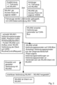
Fig. 3 eine andere Darstellung für die Abfolge der Verfahrensschritte, mit einer Verbindung zwischen Client und Access Point, -
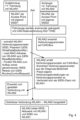
Fig. 4 eine Abfolge der Verfahrensschritte gemäßFig. 3 , jedoch mit dem Ergebnis von zwei Access Points in einem WDS-Netzwerk. - Gemäß
Fig. 1 sind ein erstes Fahrzeug 10 und ein zweites Fahrzeug 11 über eine physische Datenverbindung 12 gemäß ISO 11992 miteinander verbunden. In jedem Fahrzeug sind Steuergeräte über einen CAN-Bus 13, 14 miteinander verbunden. Im ersten Fahrzeug 10 ist ein erstes Steuergerät 15 als Bremsen-Steuergerät mit einem ersten Kommunikationsgerät 16 über den CAN-Bus 13 gekoppelt. Das erste Steuergerät 15 ist inFig. 1 zusätzlich als ECU1 bezeichnet, das erste Kommunikationsgerät als WLAN1. - Analog dazu sind im zweiten Fahrzeug 11 ein zweites Steuergerät 17 (ECU2) und ein zweites Kommunikationsgerät 18 (WLAN2) über den CAN-Bus 14 miteinander gekoppelt.
- Die beteiligten Steuergeräte 15 bis 18 kommunizieren über die CAN-Busse 13, 14 miteinander. CAN-Nachrichten eines der Steuergeräte stehen, je nach Adressierung, den anderen Steuergeräten zur Verfügung. Möglich und üblich ist die Nutzung des bekannten Netzwerkprotokolls SAE J1939 für CAN-Nachrichten.
- Die einzelnen Steuergeräte können auch Diagnose-Botschaften über die sogenannten Unified Diagnostic Services (UDS) gemäß ISO 14229 und ISO 15765-3 übersenden und lesen. Vorliegend werden derartige Diagnose-Botschaften genutzt für die Übermittlung von Verbindungsparametern zum Aufbau einer drahtlosen Verbindung zwischen den beiden Kommunikationsgeräten 16, 18.
- Das erste Fahrzeug 10 ist hier vorzugsweise ein Zugfahrzeug, das zweite Fahrzeug 11 ein Anhänger. Das erste Steuergerät 15 ist das Bremsen-Steuergerät des Zugfahrzeugs, während das zweite Steuergerät 17 das Bremsen-Steuergerät des Anhängers ist. Die beiden Bremsen-Steuergeräte sind in bekannter Weise über die physische Datenverbindung 12 miteinander verbunden und können darüber nach ISO 11992-4 auch Diagnose-Botschaften der UDS austauschen.
- Im vorliegenden Beispiel ist eine drahtlose Datenverbindung zwischen den Kommunikationsgeräten 16, 18 per WLAN vorgesehen. Das erste Kommunikationsgerät 16 ist als Access Point konfiguriert und sendet seine SSID. Gleiches gilt für das zweite Kommunikationsgerät 18, welches als Access Point eine eigene SSID aufweist. Ziel ist nun die Herstellung der WLAN-Verbindung zwischen den beiden Kommunikationsgeräten 16, 18. Hierzu übersendet das erste Kommunikationsgerät 16 die eigene SSID, eventuell Angaben zur Verschlüsselung und ein Passwort über den CAN-Bus 13, die physische Datenverbindung 12 und den CAN-Bus 14 an das zweite Kommunikationsgerät 18.
- Die angegebenen Verbindungsparameter sind verpackt in eine oder mehrere Diagnose-Botschaften der UDS. Das zweite Kommunikationsgerät 18 kann sich mit den übermittelten Daten mit dem ersten Kommunikationsgerät 16 per WLAN verbinden. Irrtümliche Verbindungen mit weiteren Fahrzeugen, die keine physische Datenverbindung zum ersten Fahrzeug 10 aufweisen, sind ausgeschlossen.
- Der Ablauf bei der Herstellung der drahtlosen Datenverbindung zwischen den beiden Fahrzeugen 10, 11 wird in Verbindung mit
Fig. 2 erläutert. Gezeigt sind Schritte A bis F: - A: Ein Zugfahrzeug als erstes Fahrzeug 10 und ein Auflieger als zweites Fahrzeug 11 sind noch nicht mechanisch gekoppelt. Das Kommunikationsgerät 16 im Zugfahrzeug sendet per WLAN seine SSID und ist mit dem CAN-Bus 13 des Zugfahrzeugs verbunden. Ebenso ist das Kommunikationsgerät 18 im Anhänger mit dem CAN-Bus 14 des Bremsen-Steuergerätes (Steuergerät 17) verbunden. Die WLAN-Reichweite des Zugfahrzeugs ist durch einen Kreis 19 dargestellt, welcher noch nicht das Kommunikationsgerät 18 im Anhänger erreicht.
- B: Der Anhänger wird an das Zugfahrzeug mechanisch angekoppelt. Das zweite Kommunikationsgerät 18 befindet sich nun im Bereich des WLAN (Kreis 19) des Zugfahrzeugs.
- C: Zugfahrzeug und Anhänger werden elektrisch und pneumatisch miteinander verbunden. Dabei wird auch die physische Datenverbindung 12 gemäß ISO 11992 hergestellt, welche die Bremsen-Steuergeräte (Steuergeräte 15 und 17) miteinander verbindet. Letztere sind in
Fig. 2 aus Platzgründen nicht dargestellt. - D: Das Bremsen-Steuergerät im Anhänger wird durch die Verbindung zum Zugfahrzeug mit Strom versorgt und meldet sich auf dem CAN-Bus 13 als Steuergerät. Das Bremsen-Steuergerät im Zugfahrzeug erkennt anhand der Nachrichten auf dem CAN-Bus, dass ein Anhänger mit Steuergerät angekoppelt wurde und gibt diese Information an das Kommunikationsgerät 16 weiter. Alternativ erkennt das Kommunikationsgerät 16 (welches selbst auch ein Steuergerät ist) selbstständig anhand der auf dem CAN-Bus 13 vorliegenden Nachrichten, dass ein Anhänger mit Steuergerät angekoppelt wurde. Daraufhin oder nach Ablauf einer definierten Zeitspanne erzeugt das Kommunikationsgerät 16 im Zugfahrzeug eine oder mehrere Diagnose-Botschaften 20 mit Informationen für die drahtlose Verbindung, insbesondere die eigene SSID und das Passwort für das WLAN des Zugfahrzeugs.
- E: Die generierten Diagnose-Botschaften 20 liegen nun auf dem CAN-Bus 13 des Zugfahrzeugs vor und werden vom Bremsen-Steuergerät über die physische Datenverbindung 12 zum Bremsen-Steuergerät des Anhängers weitergeleitet. Von dort gelangen die Diagnose-Botschaften 20 bzw. die darin enthaltenen Informationen zum Kommunikationsgerät 18 des Anhängers.
- F: Nach Erhalt der in den Diagnose-Botschaften 20 enthaltenen Informationen verbindet sich das Kommunikationsgerät 18 des Anhängers mit dem Kommunikationsgerät 16 des Zugfahrzeugs. Dabei baut das Kommunikationsgerät 18 ein WLAN 21 auf, welches auch das Kommunikationsgerät 16 erreicht.
- Im Ergebnis ist das Kommunikationsgerät 18 (Anhänger) Client im WLAN des Kommunikationsgerätes 16 (Zugfahrzeug). Alternativ können die beiden Kommunikationsgeräte 16, 18 auch per WDS ein gemeinsames Netzwerk aufspannen, um so die Reichweite eines der beiden WLANs 19, 20 zu vergrößern, oder um ein gemeinsames Netzwerk aufzubauen, sodass sämtliche Informationen, die in einem der beiden WLANs 19, 20 vorliegen, von einem Client außerhalb der beiden Netzwerke abrufbar sind.
- Die einzelnen Schritte beim Aufbau der Client-Access-Point-Verbindung sind in
Fig. 3 dargestellt. Erforderlich ist die Übergabe der Verbindungsparameter vom ersten Kommunikationsgerät 16 (WLAN1) des Zugfahrzeugs an das zweite Kommunikationsgerät 18 (WLAN2) im Anhänger. Hierzu werden die Verbindungsparameter, insbesondere SSID und Passwort, in einer UDS-Diagnose-Botschaft verpackt, nämlich als WriteDataByldentifier, und über den CAN-Bus versendet. Zusätzlich fordert das erste Kommunikationsgerät (WLAN1) zum Aufbau einer WLAN-Verbindung auf, wobei das zweite Kommunikationsgerät (WLAN2) Client sein soll. Die entsprechende UDS-Diagnose-Botschaft wird als RoutineControlRequest bezeichnet. Das zweite Kommunikationsgerät 18 (WLAN2) liest die Diagnose-Botschaften, extrahiert die Verbindungsparameter, passt die eigenen Verbindungseinstellungen an und verbindet sich als WLAN-Client mit dem ersten Kommunikationsgerät 16 (WLAN1). Die drahtlose Verbindung besteht zwischen WLAN1 als Access-Point und WLAN2 als Client. - Der Aufbau des WDS-Netzwerks ergibt sich aus
Fig. 4 und den darin enthaltenen Angaben. Wiederum erforderlich ist die Übergabe der Verbindungsparameter vom ersten Kommunikationsgerät 16 (WLAN1) des Zugfahrzeugs an das zweite Kommunikationsgerät 18 (WLAN2) im Anhänger. Hierzu werden die Verbindungsparameter, insbesondere SSID und Passwort, als WriteDataByldentifier über den CAN-Bus versendet. Zusätzlich liest WLAN1 die MAC-Adresse von WLAN2 aus. Die zugehörige UDS-Botschaft wird als ReadByldentifier bezeichnet. Außerdem fordert das erste Kommunikationsgerät (WLAN1) zum Aufbau eines gemeinsamen WDS-Netzes auf. Die entsprechende UDS-Diagnose-Botschaft wird wiederum als RoutineControlRequest bezeichnet. Das zweite Kommunikationsgerät 18 (WLAN2) liest die Diagnose-Botschaften, extrahiert die Verbindungsparameter, passt die eigenen Verbindungseinstellungen an und verbindet sich als WDS-Client mit dem ersten Kommunikationsgerät 16 (WLAN1). Daraufhin akzeptiert WLAN1 die Verbindung mit WLAN2 zu einem WDS-Netzwerk. - Im voranstehenden Text, in den Ansprüchen und Figuren sind verschiedene Normen (ISO, IEEE, SAE) genannt. Sofern nicht anders angegeben, sind die am Prioritätstag dieser Anmeldung geltenden Fassungen gemeint, oder folgende Fassungen:
- ISO 11992 --> ISO 11992-1: Interchange of digital information on electrical connections between towing and towed vehicles, Part 1: Physical and Data Link Layer, 2001-11-20.
- ISO 11992-4: Interchange of digital information on electrical connections between towing and towed vehicles, Part 4: Diagnostics, 2003-01-27.
- ISO 14229 UDS, Part 1: Specification and requirements, 2004-10-07.
- ISO 15765 Diagnostics on CAN, Part 1: General information, 2003-04-20.
- ISO 15765-3 Diagnostics on CAN, Part 3: Implementation of diagnostic services, 2003-05-12.
- SAE J1939-11 Physical layer 250K bits twisted shielded pair, 09/2006.
- IEEE 802.11 --> IEEE 802 Part 11: Wireless LAN Medium Access Control (MAC) and Physical Layer (PHY) Specifications, 2012-03-29.
Claims (7)
- Verfahren zum Aufbau einer drahtlosen Datenverbindung zwischen wenigstens zwei Fahrzeugen (10, 11), welche über eine physische Datenverbindung (12) miteinander verbunden sind, wobei nach Anschluss der physischen Datenverbindung zunächst Verbindungsparameter der drahtlosen Verbindung über die physische Datenverbindung (12) von dem Zugfahrzeug (10) zu dem angeschlossenen Anhängerfahrzeug (11) übermittelt werden, wobei die drahtlose Datenverbindung zwischen den Fahrzeugen (10, 11) eine WLAN-Verbindung ist, die wenigstens zwei Fahrzeuge (10, 11) mit je einem WLAN-Kommunikationsmodul (16, 18) ausgestattet sind und die Verbindungsparameter für den Aufbau der WLAN-Verbindung vorgesehen sind und dann die drahtlose Verbindung mit den Verbindungsparametern aufgebaut wird, wobei die physische Datenverbindung (12) eine CAN-Verbindung nach ISO 11992 ist, in der am Prioritätstag dieser Anmeldung geltenden Fassung oder als ISO 11992 mit ISO 11992-1: Interchange of digital information on electrical connections between towing and towed vehicles, Part 1: Physical and Data Link Layer, 2001-11-20, dadurch gekennzeichnet, dass die Verbindungsparameter als Teil einer Diagnose-Botschaft in der Form des Unified Diagnostic Services, UDS, nach ISO 14229 und ISO 15765 übermittelt werden, in der am Prioritätstag dieser Anmeldung geltenden Fassung der Normen ISO 14229 und ISO 15765 oder als ISO 14229 UDS, Part 1: Specification and requirements, 2004-10-07, und ISO 15765 Diagnostics on CAN, Part 1: General information, 2003-04-20, wobei das Zugfahrzeug (10) mit einer weiteren Diagnose-Botschaft die MAC-Adresse des WLAN-Kommunikationsgerätes (18) im Anhängerfahrzeug (11) ausliest.
- Verfahren nach Anspruch 1 oder einem der weiteren voranstehenden Ansprüche, dadurch gekennzeichnet, dass die Verbindungsparameter wenigstens einen der Parameter SSID, Passwort, Identifizierung wenigstens eines der Fahrzeuge, Netzwerk-Adresse, MAC-Adresse enthalten.
- Verfahren nach Anspruch 1 oder einem der weiteren voranstehenden Ansprüche, gekennzeichnet durch folgende Merkmale:a) im ersten Fahrzeug (10) sind ein erstes Kommunikationsgerät (16) und ein erstes Steuergerät (15) vorgesehen, im zweiten Fahrzeug (11) sind ein zweites Kommunikationsgerät (18) und ein zweites Steuergerät (17) vorgesehen,b) die beiden Kommunikationsgeräte (16, 18) können über die drahtlose Datenverbindung miteinander kommunizieren,c) das erste Kommunikationsgerät (16) und das erste Steuergerät (15) können über eine erste drahtgebundene Datenverbindung miteinander kommunizieren,d) das zweite Kommunikationsgerät (18) und das zweite Steuergerät (17) können über eine zweite drahtgebundene Datenverbindung miteinander kommunizieren,e) nach Herstellung der physischen Datenverbindung (12) zwischen dem ersten Steuergerät (15) und dem zweiten Steuergerät (17) sendet das erste Steuergerät (15) über die physische Datenverbindung (12) und das zweite Steuergerät (17) die Verbindungsparameter für die drahtlose Datenverbindung an das zweite Kommunikationsgerät (18),f) nach Erhalt der Verbindungsparameter baut das zweite Kommunikationsgerät (18) mit dem ersten Kommunikationsgerät (16) die drahtlose Verbindung auf.
- Verfahren nach Anspruch 3, dadurch gekennzeichnet, dass das erste Kommunikationsgerät (16) und das erste Steuergerät (15) über einen CAN-Bus (13) verbunden sind und Daten insbesondere gemäß dem Netzwerkprotokoll SAE J1939 übertragen werden, mit der am Prioritätstag dieser Anmeldung geltenden Fassung der Norm SAE J1939 oder als SAE J1939-11 Physical layer 250K bits twisted shielded pair, 09/2006.
- Verfahren nach Anspruch 3 oder 4, dadurch gekennzeichnet, dass das zweite Kommunikationsgerät (18) und das zweite Steuergerät (17) über einen CAN-Bus (14) verbunden sind.
- Steuergerät für ein Zugfahrzeug, dadurch gekennzeichnet, dass das Steuergerät zur Durchführung des Verfahrens nach einem der voranstehenden Ansprüche 1 bis 5 angepasst ist.
- Kommunikationsgerät für ein Zugfahrzeug, dadurch gekennzeichnet, dass das Kommunikationsgerät (16) zur Durchführung des Verfahrens nach einem der Ansprüche 1 bis 5 angepasst ist.
Applications Claiming Priority (2)
| Application Number | Priority Date | Filing Date | Title |
|---|---|---|---|
| DE102017002633.5A DE102017002633A1 (de) | 2017-03-17 | 2017-03-17 | Verfahren zum Aufbau einer drahtlosen Datenverbindung |
| PCT/EP2018/056009 WO2018166940A1 (de) | 2017-03-17 | 2018-03-12 | Verfahren zum aufbau einer drahtlosen datenverbindung |
Publications (2)
| Publication Number | Publication Date |
|---|---|
| EP3596889A1 EP3596889A1 (de) | 2020-01-22 |
| EP3596889B1 true EP3596889B1 (de) | 2025-04-09 |
Family
ID=61627108
Family Applications (1)
| Application Number | Title | Priority Date | Filing Date |
|---|---|---|---|
| EP18710852.7A Active EP3596889B1 (de) | 2017-03-17 | 2018-03-12 | Verfahren zum aufbau einer drahtlosen datenverbindung |
Country Status (6)
| Country | Link |
|---|---|
| US (1) | US11457484B2 (de) |
| EP (1) | EP3596889B1 (de) |
| CN (1) | CN110383771A (de) |
| BR (1) | BR112019019246A2 (de) |
| DE (1) | DE102017002633A1 (de) |
| WO (1) | WO2018166940A1 (de) |
Families Citing this family (5)
| Publication number | Priority date | Publication date | Assignee | Title |
|---|---|---|---|---|
| US20200130454A1 (en) * | 2018-10-30 | 2020-04-30 | Air Lift Company | Method of operating vehicle control system |
| US11140730B2 (en) * | 2019-03-15 | 2021-10-05 | Cisco Technology, Inc. | Automatic provisioning of Wi-Fi connections for trailers |
| CN110933736B (zh) * | 2019-11-27 | 2020-11-27 | 安徽江淮汽车集团股份有限公司 | 车载控制器通讯方法、装置、设备及存储介质 |
| DE102020115404A1 (de) | 2020-06-10 | 2021-12-16 | Knorr-Bremse Systeme für Nutzfahrzeuge GmbH | Kommunikationseinrichtung und Verfahren zum Übermitteln und Empfangen von Informationen für ein Solo-Fahrzeug oder eine Fahrzeugkombination bestehend aus einem Zugfahrzeug und mindestens einem Anhänger |
| CN112929988A (zh) * | 2021-03-23 | 2021-06-08 | 上海商汤临港智能科技有限公司 | 车载设备的配对方法及装置、电子设备和存储介质 |
Family Cites Families (7)
| Publication number | Priority date | Publication date | Assignee | Title |
|---|---|---|---|---|
| DE10044034A1 (de) * | 2000-09-06 | 2002-04-11 | Wabco Gmbh & Co Ohg | Verfahren zum Datenaustausch zwischen Zugfahrzeug und Anhänger |
| KR101299400B1 (ko) * | 2005-11-02 | 2013-08-22 | 인터디지탈 테크날러지 코포레이션 | 무선 분배 시스템에 대한 자율적인 채널 코디네이션 방법 및 장치 |
| US7760077B2 (en) * | 2007-06-05 | 2010-07-20 | Qualcomm Incorporated | Establishing and securing a unique wireless RF link between a tractor and a trailer using a wired connection |
| CN202013653U (zh) | 2010-03-15 | 2011-10-19 | 朱曼平 | 一种遥控点菜车 |
| DE102013217684A1 (de) * | 2013-09-04 | 2015-03-05 | Continental Automotive Gmbh | Verfahren und Anordnung zum Aufbau einer Funkverbindung |
| DE102014004182A1 (de) | 2014-03-22 | 2015-09-24 | Wabco Gmbh | Verfahren zum Herstellen einer drahtlosen Verbindung |
| DE102014015394A1 (de) | 2014-10-17 | 2016-04-21 | Wabco Gmbh | Verfahren zum Aufbau und Betrieb eines drahtlosen Fahrzeug-Netzwerks |
-
2017
- 2017-03-17 DE DE102017002633.5A patent/DE102017002633A1/de active Pending
-
2018
- 2018-03-12 BR BR112019019246A patent/BR112019019246A2/pt not_active IP Right Cessation
- 2018-03-12 EP EP18710852.7A patent/EP3596889B1/de active Active
- 2018-03-12 CN CN201880014281.2A patent/CN110383771A/zh active Pending
- 2018-03-12 US US16/486,843 patent/US11457484B2/en active Active
- 2018-03-12 WO PCT/EP2018/056009 patent/WO2018166940A1/de not_active Ceased
Also Published As
| Publication number | Publication date |
|---|---|
| DE102017002633A1 (de) | 2018-09-20 |
| CN110383771A (zh) | 2019-10-25 |
| WO2018166940A1 (de) | 2018-09-20 |
| EP3596889A1 (de) | 2020-01-22 |
| US11457484B2 (en) | 2022-09-27 |
| BR112019019246A2 (pt) | 2020-04-14 |
| US20200236722A1 (en) | 2020-07-23 |
Similar Documents
| Publication | Publication Date | Title |
|---|---|---|
| EP3596889B1 (de) | Verfahren zum aufbau einer drahtlosen datenverbindung | |
| EP3207537B1 (de) | Verfahren zum aufbau und betrieb eines drahtlosen fahrzeug-netzwerks | |
| EP3507966B1 (de) | Verfahren zum aufbau eines drahtlosen fahrzeug-netzwerks | |
| EP3183937B1 (de) | Verfahren zum aufbau eines fahrzeug-netzwerks | |
| EP2795848B1 (de) | Teilnehmerstation eines bussystems und verfahren zur übertragung von nachrichten zwischen teilnehmerstationen eines bussystems | |
| EP1516292A1 (de) | Verfahren und vorrichtung für einen fahrzeugbezogenen telematikdienst | |
| DE102021106574A1 (de) | Vorabprofilkopplung für mobile vorrichtung und fahrzeug | |
| DE112011100694T5 (de) | Kommunikationsverbinder, Kommunikationskabelbaum und Kommunikatiossystem | |
| DE102015219928A1 (de) | Fahrzeugvernetzungsmodul zum Bereitstellen eines drahtlosen Hotspots | |
| WO2017102787A1 (de) | Kraftfahrzeug-dachantennenmodul, kraftfahrzeug und verfahren zum betreiben des dachantennenmoduls | |
| EP3158465B1 (de) | Verfahren, vorrichtung und system zum aufbau und zum betrieb eines drahtlosen netzwerks | |
| EP3044912A1 (de) | Verfahren zur bereitstellung und übertragung von daten, insbesondere in verbindung mit einem fahrzeug | |
| DE102018112146A1 (de) | Drahtlose fahrzeuginterne kommunikations- und informationsbereitstellung durch fahrzeuge | |
| DE102018105612A1 (de) | Fahrzeugkommunikation | |
| DE102023127213A1 (de) | Übertragung von Authentifizierungsschlüsseln | |
| WO2018145826A1 (de) | Verfahren zur positionsbestimmung eines mobilen ble-geräts | |
| DE102013001412A1 (de) | Verfahren zur Steuerung einer Kommunikation zwischen einer Diagnosestelle eines Fahrzeugs und einem Fahrzeugnetz sowie entsprechende Steuerung für ein Fahrzeug | |
| DE102008039170A1 (de) | Automatische Konfiguration von Teilsystemen und Kommunikation zwischen Systemen in Fahrzeugen | |
| DE102023104930A1 (de) | Verfahren und Vorrichtung zur Festlegung der Signifikanz einer Fahrzeug-Kommunikationsverbindung | |
| DE102018207445B4 (de) | Verfahren zum Bereitstellen von Benutzerdaten auf einem Kommunikationsgerät, zentrale Datenverarbeitungseinrichtung und Kommunikationssystem | |
| DE102018202701B4 (de) | Verfahren, Vorrichtung und Computerprogramm zum Bereitstellen eines definierten Funkzugangs für ein Mobilgerät durch einen Zugangsknoten | |
| DE102016206774A1 (de) | Verfahren zum Betreiben eines Kommunikationssystems für ein Fahrzeug und Kommunikationssystem | |
| EP3285436A1 (de) | Netzwerk für einen fahrzeugverbund und verfahren zum herstellen eines netzwerks für einen fahrzeugverbund | |
| DE102023129117A1 (de) | Übertragung von authentifizierungsschlüsseln | |
| DE102015210534A1 (de) | Verfahren zum Betreiben einer externen Schnittstelle in einem Steuergerätverbund |
Legal Events
| Date | Code | Title | Description |
|---|---|---|---|
| STAA | Information on the status of an ep patent application or granted ep patent |
Free format text: STATUS: UNKNOWN |
|
| STAA | Information on the status of an ep patent application or granted ep patent |
Free format text: STATUS: THE INTERNATIONAL PUBLICATION HAS BEEN MADE |
|
| PUAI | Public reference made under article 153(3) epc to a published international application that has entered the european phase |
Free format text: ORIGINAL CODE: 0009012 |
|
| STAA | Information on the status of an ep patent application or granted ep patent |
Free format text: STATUS: REQUEST FOR EXAMINATION WAS MADE |
|
| 17P | Request for examination filed |
Effective date: 20191017 |
|
| AK | Designated contracting states |
Kind code of ref document: A1 Designated state(s): AL AT BE BG CH CY CZ DE DK EE ES FI FR GB GR HR HU IE IS IT LI LT LU LV MC MK MT NL NO PL PT RO RS SE SI SK SM TR |
|
| AX | Request for extension of the european patent |
Extension state: BA ME |
|
| DAV | Request for validation of the european patent (deleted) | ||
| DAX | Request for extension of the european patent (deleted) | ||
| STAA | Information on the status of an ep patent application or granted ep patent |
Free format text: STATUS: EXAMINATION IS IN PROGRESS |
|
| RAP3 | Party data changed (applicant data changed or rights of an application transferred) |
Owner name: ZF CV SYSTEMS HANNOVER GMBH |
|
| 17Q | First examination report despatched |
Effective date: 20210518 |
|
| RAP1 | Party data changed (applicant data changed or rights of an application transferred) |
Owner name: ZF CV SYSTEMS EUROPE BV |
|
| GRAP | Despatch of communication of intention to grant a patent |
Free format text: ORIGINAL CODE: EPIDOSNIGR1 |
|
| STAA | Information on the status of an ep patent application or granted ep patent |
Free format text: STATUS: GRANT OF PATENT IS INTENDED |
|
| RIC1 | Information provided on ipc code assigned before grant |
Ipc: H04L 41/0806 20220101ALI20241031BHEP Ipc: H04W 84/12 20090101ALI20241031BHEP Ipc: H04L 12/40 20060101AFI20241031BHEP |
|
| INTG | Intention to grant announced |
Effective date: 20241111 |
|
| GRAS | Grant fee paid |
Free format text: ORIGINAL CODE: EPIDOSNIGR3 |
|
| GRAA | (expected) grant |
Free format text: ORIGINAL CODE: 0009210 |
|
| STAA | Information on the status of an ep patent application or granted ep patent |
Free format text: STATUS: THE PATENT HAS BEEN GRANTED |
|
| AK | Designated contracting states |
Kind code of ref document: B1 Designated state(s): AL AT BE BG CH CY CZ DE DK EE ES FI FR GB GR HR HU IE IS IT LI LT LU LV MC MK MT NL NO PL PT RO RS SE SI SK SM TR |
|
| REG | Reference to a national code |
Ref country code: GB Ref legal event code: FG4D Free format text: NOT ENGLISH |
|
| REG | Reference to a national code |
Ref country code: CH Ref legal event code: EP |
|
| REG | Reference to a national code |
Ref country code: DE Ref legal event code: R096 Ref document number: 502018015725 Country of ref document: DE |
|
| REG | Reference to a national code |
Ref country code: IE Ref legal event code: FG4D Free format text: LANGUAGE OF EP DOCUMENT: GERMAN |
|
| REG | Reference to a national code |
Ref country code: NL Ref legal event code: MP Effective date: 20250409 |
|
| PG25 | Lapsed in a contracting state [announced via postgrant information from national office to epo] |
Ref country code: NL Free format text: LAPSE BECAUSE OF FAILURE TO SUBMIT A TRANSLATION OF THE DESCRIPTION OR TO PAY THE FEE WITHIN THE PRESCRIBED TIME-LIMIT Effective date: 20250409 |
|
| PG25 | Lapsed in a contracting state [announced via postgrant information from national office to epo] |
Ref country code: ES Free format text: LAPSE BECAUSE OF FAILURE TO SUBMIT A TRANSLATION OF THE DESCRIPTION OR TO PAY THE FEE WITHIN THE PRESCRIBED TIME-LIMIT Effective date: 20250409 Ref country code: PT Free format text: LAPSE BECAUSE OF FAILURE TO SUBMIT A TRANSLATION OF THE DESCRIPTION OR TO PAY THE FEE WITHIN THE PRESCRIBED TIME-LIMIT Effective date: 20250811 Ref country code: FI Free format text: LAPSE BECAUSE OF FAILURE TO SUBMIT A TRANSLATION OF THE DESCRIPTION OR TO PAY THE FEE WITHIN THE PRESCRIBED TIME-LIMIT Effective date: 20250409 |
|
| REG | Reference to a national code |
Ref country code: LT Ref legal event code: MG9D |
|
| PG25 | Lapsed in a contracting state [announced via postgrant information from national office to epo] |
Ref country code: GR Free format text: LAPSE BECAUSE OF FAILURE TO SUBMIT A TRANSLATION OF THE DESCRIPTION OR TO PAY THE FEE WITHIN THE PRESCRIBED TIME-LIMIT Effective date: 20250710 Ref country code: NO Free format text: LAPSE BECAUSE OF FAILURE TO SUBMIT A TRANSLATION OF THE DESCRIPTION OR TO PAY THE FEE WITHIN THE PRESCRIBED TIME-LIMIT Effective date: 20250709 |
|
| PG25 | Lapsed in a contracting state [announced via postgrant information from national office to epo] |
Ref country code: PL Free format text: LAPSE BECAUSE OF FAILURE TO SUBMIT A TRANSLATION OF THE DESCRIPTION OR TO PAY THE FEE WITHIN THE PRESCRIBED TIME-LIMIT Effective date: 20250409 |
|
| PG25 | Lapsed in a contracting state [announced via postgrant information from national office to epo] |
Ref country code: BG Free format text: LAPSE BECAUSE OF FAILURE TO SUBMIT A TRANSLATION OF THE DESCRIPTION OR TO PAY THE FEE WITHIN THE PRESCRIBED TIME-LIMIT Effective date: 20250409 |
|
| PG25 | Lapsed in a contracting state [announced via postgrant information from national office to epo] |
Ref country code: HR Free format text: LAPSE BECAUSE OF FAILURE TO SUBMIT A TRANSLATION OF THE DESCRIPTION OR TO PAY THE FEE WITHIN THE PRESCRIBED TIME-LIMIT Effective date: 20250409 |
|
| PG25 | Lapsed in a contracting state [announced via postgrant information from national office to epo] |
Ref country code: RS Free format text: LAPSE BECAUSE OF FAILURE TO SUBMIT A TRANSLATION OF THE DESCRIPTION OR TO PAY THE FEE WITHIN THE PRESCRIBED TIME-LIMIT Effective date: 20250709 |
|
| PG25 | Lapsed in a contracting state [announced via postgrant information from national office to epo] |
Ref country code: IS Free format text: LAPSE BECAUSE OF FAILURE TO SUBMIT A TRANSLATION OF THE DESCRIPTION OR TO PAY THE FEE WITHIN THE PRESCRIBED TIME-LIMIT Effective date: 20250809 |
|
| PG25 | Lapsed in a contracting state [announced via postgrant information from national office to epo] |
Ref country code: LV Free format text: LAPSE BECAUSE OF FAILURE TO SUBMIT A TRANSLATION OF THE DESCRIPTION OR TO PAY THE FEE WITHIN THE PRESCRIBED TIME-LIMIT Effective date: 20250409 |
|
| REG | Reference to a national code |
Ref country code: DE Ref legal event code: R097 Ref document number: 502018015725 Country of ref document: DE |
|
| PG25 | Lapsed in a contracting state [announced via postgrant information from national office to epo] |
Ref country code: SM Free format text: LAPSE BECAUSE OF FAILURE TO SUBMIT A TRANSLATION OF THE DESCRIPTION OR TO PAY THE FEE WITHIN THE PRESCRIBED TIME-LIMIT Effective date: 20250409 Ref country code: DK Free format text: LAPSE BECAUSE OF FAILURE TO SUBMIT A TRANSLATION OF THE DESCRIPTION OR TO PAY THE FEE WITHIN THE PRESCRIBED TIME-LIMIT Effective date: 20250409 |
|
| PG25 | Lapsed in a contracting state [announced via postgrant information from national office to epo] |
Ref country code: CZ Free format text: LAPSE BECAUSE OF FAILURE TO SUBMIT A TRANSLATION OF THE DESCRIPTION OR TO PAY THE FEE WITHIN THE PRESCRIBED TIME-LIMIT Effective date: 20250409 |
|
| PG25 | Lapsed in a contracting state [announced via postgrant information from national office to epo] |
Ref country code: EE Free format text: LAPSE BECAUSE OF FAILURE TO SUBMIT A TRANSLATION OF THE DESCRIPTION OR TO PAY THE FEE WITHIN THE PRESCRIBED TIME-LIMIT Effective date: 20250409 |
|
| PG25 | Lapsed in a contracting state [announced via postgrant information from national office to epo] |
Ref country code: RO Free format text: LAPSE BECAUSE OF FAILURE TO SUBMIT A TRANSLATION OF THE DESCRIPTION OR TO PAY THE FEE WITHIN THE PRESCRIBED TIME-LIMIT Effective date: 20250409 Ref country code: SK Free format text: LAPSE BECAUSE OF FAILURE TO SUBMIT A TRANSLATION OF THE DESCRIPTION OR TO PAY THE FEE WITHIN THE PRESCRIBED TIME-LIMIT Effective date: 20250409 |
|
| PG25 | Lapsed in a contracting state [announced via postgrant information from national office to epo] |
Ref country code: IT Free format text: LAPSE BECAUSE OF FAILURE TO SUBMIT A TRANSLATION OF THE DESCRIPTION OR TO PAY THE FEE WITHIN THE PRESCRIBED TIME-LIMIT Effective date: 20250409 |
|
| PLBE | No opposition filed within time limit |
Free format text: ORIGINAL CODE: 0009261 |
|
| STAA | Information on the status of an ep patent application or granted ep patent |
Free format text: STATUS: NO OPPOSITION FILED WITHIN TIME LIMIT |
|
| REG | Reference to a national code |
Ref country code: CH Ref legal event code: L10 Free format text: ST27 STATUS EVENT CODE: U-0-0-L10-L00 (AS PROVIDED BY THE NATIONAL OFFICE) Effective date: 20260218 |
|
| 26N | No opposition filed |
Effective date: 20260112 |