EP3597154A1 - Magnetische bandscheibenersatzvorrichtungen - Google Patents
Magnetische bandscheibenersatzvorrichtungen Download PDFInfo
- Publication number
- EP3597154A1 EP3597154A1 EP19186887.6A EP19186887A EP3597154A1 EP 3597154 A1 EP3597154 A1 EP 3597154A1 EP 19186887 A EP19186887 A EP 19186887A EP 3597154 A1 EP3597154 A1 EP 3597154A1
- Authority
- EP
- European Patent Office
- Prior art keywords
- plate
- magnets
- superior
- inferior
- intervertebral disc
- Prior art date
- Legal status (The legal status is an assumption and is not a legal conclusion. Google has not performed a legal analysis and makes no representation as to the accuracy of the status listed.)
- Pending
Links
- 125000006850 spacer group Chemical group 0.000 claims abstract description 78
- 239000000463 material Substances 0.000 claims description 28
- 206010061246 Intervertebral disc degeneration Diseases 0.000 claims description 22
- 208000018180 degenerative disc disease Diseases 0.000 claims description 22
- 208000021600 intervertebral disc degenerative disease Diseases 0.000 claims description 22
- 230000033001 locomotion Effects 0.000 description 56
- 238000000926 separation method Methods 0.000 description 30
- 238000000034 method Methods 0.000 description 22
- 238000002513 implantation Methods 0.000 description 20
- 229910052761 rare earth metal Inorganic materials 0.000 description 10
- 150000002910 rare earth metals Chemical class 0.000 description 10
- XEEYBQQBJWHFJM-UHFFFAOYSA-N Iron Chemical compound [Fe] XEEYBQQBJWHFJM-UHFFFAOYSA-N 0.000 description 8
- MCMNRKCIXSYSNV-UHFFFAOYSA-N Zirconium dioxide Chemical compound O=[Zr]=O MCMNRKCIXSYSNV-UHFFFAOYSA-N 0.000 description 8
- 238000004458 analytical method Methods 0.000 description 8
- 229910052751 metal Inorganic materials 0.000 description 7
- 239000002184 metal Substances 0.000 description 7
- PXHVJJICTQNCMI-UHFFFAOYSA-N Nickel Chemical compound [Ni] PXHVJJICTQNCMI-UHFFFAOYSA-N 0.000 description 6
- 239000011248 coating agent Substances 0.000 description 6
- 238000000576 coating method Methods 0.000 description 6
- 230000000694 effects Effects 0.000 description 6
- 238000011282 treatment Methods 0.000 description 6
- 239000004696 Poly ether ether ketone Substances 0.000 description 5
- 230000008901 benefit Effects 0.000 description 5
- 229920002530 polyetherether ketone Polymers 0.000 description 5
- 229910045601 alloy Inorganic materials 0.000 description 4
- 239000000956 alloy Substances 0.000 description 4
- 239000000919 ceramic Substances 0.000 description 4
- 238000013461 design Methods 0.000 description 4
- 239000007943 implant Substances 0.000 description 4
- 229910001172 neodymium magnet Inorganic materials 0.000 description 4
- TWNQGVIAIRXVLR-UHFFFAOYSA-N oxo(oxoalumanyloxy)alumane Chemical compound O=[Al]O[Al]=O TWNQGVIAIRXVLR-UHFFFAOYSA-N 0.000 description 4
- 230000009467 reduction Effects 0.000 description 4
- 238000001356 surgical procedure Methods 0.000 description 4
- 210000001519 tissue Anatomy 0.000 description 4
- RTAQQCXQSZGOHL-UHFFFAOYSA-N Titanium Chemical compound [Ti] RTAQQCXQSZGOHL-UHFFFAOYSA-N 0.000 description 3
- 230000000975 bioactive effect Effects 0.000 description 3
- 229920001222 biopolymer Polymers 0.000 description 3
- 239000000788 chromium alloy Substances 0.000 description 3
- 239000010941 cobalt Substances 0.000 description 3
- 229910017052 cobalt Inorganic materials 0.000 description 3
- GUTLYIVDDKVIGB-UHFFFAOYSA-N cobalt atom Chemical compound [Co] GUTLYIVDDKVIGB-UHFFFAOYSA-N 0.000 description 3
- 230000007850 degeneration Effects 0.000 description 3
- 238000010494 dissociation reaction Methods 0.000 description 3
- 230000005593 dissociations Effects 0.000 description 3
- 229910052742 iron Inorganic materials 0.000 description 3
- 229910052759 nickel Inorganic materials 0.000 description 3
- 229920000642 polymer Polymers 0.000 description 3
- 229910000982 rare earth metal group alloy Inorganic materials 0.000 description 3
- 230000035882 stress Effects 0.000 description 3
- 239000010936 titanium Substances 0.000 description 3
- 229910052719 titanium Inorganic materials 0.000 description 3
- 210000002517 zygapophyseal joint Anatomy 0.000 description 3
- 230000002159 abnormal effect Effects 0.000 description 2
- 230000002411 adverse Effects 0.000 description 2
- 210000000845 cartilage Anatomy 0.000 description 2
- 238000006243 chemical reaction Methods 0.000 description 2
- 230000006835 compression Effects 0.000 description 2
- 238000007906 compression Methods 0.000 description 2
- 230000004927 fusion Effects 0.000 description 2
- 239000000203 mixture Substances 0.000 description 2
- 210000005036 nerve Anatomy 0.000 description 2
- 230000035479 physiological effects, processes and functions Effects 0.000 description 2
- 230000008569 process Effects 0.000 description 2
- 210000000954 sacrococcygeal region Anatomy 0.000 description 2
- 238000004088 simulation Methods 0.000 description 2
- 208000024891 symptom Diseases 0.000 description 2
- 238000013519 translation Methods 0.000 description 2
- 230000014616 translation Effects 0.000 description 2
- 229910000521 B alloy Inorganic materials 0.000 description 1
- ZOXJGFHDIHLPTG-UHFFFAOYSA-N Boron Chemical compound [B] ZOXJGFHDIHLPTG-UHFFFAOYSA-N 0.000 description 1
- 229910000684 Cobalt-chrome Inorganic materials 0.000 description 1
- 229910000640 Fe alloy Inorganic materials 0.000 description 1
- 229910000583 Nd alloy Inorganic materials 0.000 description 1
- 239000004698 Polyethylene Substances 0.000 description 1
- 229910001069 Ti alloy Inorganic materials 0.000 description 1
- 206010066901 Treatment failure Diseases 0.000 description 1
- 208000027418 Wounds and injury Diseases 0.000 description 1
- WAIPAZQMEIHHTJ-UHFFFAOYSA-N [Cr].[Co] Chemical compound [Cr].[Co] WAIPAZQMEIHHTJ-UHFFFAOYSA-N 0.000 description 1
- 230000032683 aging Effects 0.000 description 1
- 206010003246 arthritis Diseases 0.000 description 1
- 238000011882 arthroplasty Methods 0.000 description 1
- 210000000988 bone and bone Anatomy 0.000 description 1
- 230000008859 change Effects 0.000 description 1
- 239000010952 cobalt-chrome Substances 0.000 description 1
- 238000010276 construction Methods 0.000 description 1
- 230000005347 demagnetization Effects 0.000 description 1
- 230000001627 detrimental effect Effects 0.000 description 1
- 201000010099 disease Diseases 0.000 description 1
- 208000037265 diseases, disorders, signs and symptoms Diseases 0.000 description 1
- 229920001971 elastomer Polymers 0.000 description 1
- 238000005516 engineering process Methods 0.000 description 1
- 230000007717 exclusion Effects 0.000 description 1
- 239000004744 fabric Substances 0.000 description 1
- 239000012530 fluid Substances 0.000 description 1
- 230000036541 health Effects 0.000 description 1
- 208000014674 injury Diseases 0.000 description 1
- 238000013150 knee replacement Methods 0.000 description 1
- 210000003041 ligament Anatomy 0.000 description 1
- 210000004705 lumbosacral region Anatomy 0.000 description 1
- 230000005389 magnetism Effects 0.000 description 1
- 238000005259 measurement Methods 0.000 description 1
- 150000002739 metals Chemical class 0.000 description 1
- 230000003278 mimic effect Effects 0.000 description 1
- 238000012986 modification Methods 0.000 description 1
- 230000004048 modification Effects 0.000 description 1
- 239000002245 particle Substances 0.000 description 1
- 239000004033 plastic Substances 0.000 description 1
- 229920003023 plastic Polymers 0.000 description 1
- -1 polyethylene Polymers 0.000 description 1
- 229920000573 polyethylene Polymers 0.000 description 1
- 229920002635 polyurethane Polymers 0.000 description 1
- 239000004814 polyurethane Substances 0.000 description 1
- 239000007779 soft material Substances 0.000 description 1
- 239000000126 substance Substances 0.000 description 1
- 210000000115 thoracic cavity Anatomy 0.000 description 1
- 238000011541 total hip replacement Methods 0.000 description 1
- 230000008733 trauma Effects 0.000 description 1
Images








Classifications
-
- A—HUMAN NECESSITIES
- A61—MEDICAL OR VETERINARY SCIENCE; HYGIENE
- A61F—FILTERS IMPLANTABLE INTO BLOOD VESSELS; PROSTHESES; DEVICES PROVIDING PATENCY TO, OR PREVENTING COLLAPSING OF, TUBULAR STRUCTURES OF THE BODY, e.g. STENTS; ORTHOPAEDIC, NURSING OR CONTRACEPTIVE DEVICES; FOMENTATION; TREATMENT OR PROTECTION OF EYES OR EARS; BANDAGES, DRESSINGS OR ABSORBENT PADS; FIRST-AID KITS
- A61F2/00—Filters implantable into blood vessels; Prostheses, i.e. artificial substitutes or replacements for parts of the body; Appliances for connecting them with the body; Devices providing patency to, or preventing collapsing of, tubular structures of the body, e.g. stents
- A61F2/02—Prostheses implantable into the body
- A61F2/30—Joints
- A61F2/44—Joints for the spine, e.g. vertebrae, spinal discs
- A61F2/442—Intervertebral or spinal discs, e.g. resilient
- A61F2/4425—Intervertebral or spinal discs, e.g. resilient made of articulated components
-
- A—HUMAN NECESSITIES
- A61—MEDICAL OR VETERINARY SCIENCE; HYGIENE
- A61F—FILTERS IMPLANTABLE INTO BLOOD VESSELS; PROSTHESES; DEVICES PROVIDING PATENCY TO, OR PREVENTING COLLAPSING OF, TUBULAR STRUCTURES OF THE BODY, e.g. STENTS; ORTHOPAEDIC, NURSING OR CONTRACEPTIVE DEVICES; FOMENTATION; TREATMENT OR PROTECTION OF EYES OR EARS; BANDAGES, DRESSINGS OR ABSORBENT PADS; FIRST-AID KITS
- A61F2/00—Filters implantable into blood vessels; Prostheses, i.e. artificial substitutes or replacements for parts of the body; Appliances for connecting them with the body; Devices providing patency to, or preventing collapsing of, tubular structures of the body, e.g. stents
- A61F2/02—Prostheses implantable into the body
- A61F2/30—Joints
- A61F2002/30001—Additional features of subject-matter classified in A61F2/28, A61F2/30 and subgroups thereof
- A61F2002/30003—Material related properties of the prosthesis or of a coating on the prosthesis
- A61F2002/3006—Properties of materials and coating materials
- A61F2002/30079—Properties of materials and coating materials magnetic
-
- A—HUMAN NECESSITIES
- A61—MEDICAL OR VETERINARY SCIENCE; HYGIENE
- A61F—FILTERS IMPLANTABLE INTO BLOOD VESSELS; PROSTHESES; DEVICES PROVIDING PATENCY TO, OR PREVENTING COLLAPSING OF, TUBULAR STRUCTURES OF THE BODY, e.g. STENTS; ORTHOPAEDIC, NURSING OR CONTRACEPTIVE DEVICES; FOMENTATION; TREATMENT OR PROTECTION OF EYES OR EARS; BANDAGES, DRESSINGS OR ABSORBENT PADS; FIRST-AID KITS
- A61F2/00—Filters implantable into blood vessels; Prostheses, i.e. artificial substitutes or replacements for parts of the body; Appliances for connecting them with the body; Devices providing patency to, or preventing collapsing of, tubular structures of the body, e.g. stents
- A61F2/02—Prostheses implantable into the body
- A61F2/30—Joints
- A61F2/44—Joints for the spine, e.g. vertebrae, spinal discs
- A61F2/442—Intervertebral or spinal discs, e.g. resilient
- A61F2/4425—Intervertebral or spinal discs, e.g. resilient made of articulated components
- A61F2002/443—Intervertebral or spinal discs, e.g. resilient made of articulated components having two transversal endplates and at least one intermediate component
-
- A—HUMAN NECESSITIES
- A61—MEDICAL OR VETERINARY SCIENCE; HYGIENE
- A61F—FILTERS IMPLANTABLE INTO BLOOD VESSELS; PROSTHESES; DEVICES PROVIDING PATENCY TO, OR PREVENTING COLLAPSING OF, TUBULAR STRUCTURES OF THE BODY, e.g. STENTS; ORTHOPAEDIC, NURSING OR CONTRACEPTIVE DEVICES; FOMENTATION; TREATMENT OR PROTECTION OF EYES OR EARS; BANDAGES, DRESSINGS OR ABSORBENT PADS; FIRST-AID KITS
- A61F2220/00—Fixations or connections for prostheses classified in groups A61F2/00 - A61F2/26 or A61F2/82 or A61F9/00 or A61F11/00 or subgroups thereof
- A61F2220/0025—Connections or couplings between prosthetic parts, e.g. between modular parts; Connecting elements
-
- A—HUMAN NECESSITIES
- A61—MEDICAL OR VETERINARY SCIENCE; HYGIENE
- A61F—FILTERS IMPLANTABLE INTO BLOOD VESSELS; PROSTHESES; DEVICES PROVIDING PATENCY TO, OR PREVENTING COLLAPSING OF, TUBULAR STRUCTURES OF THE BODY, e.g. STENTS; ORTHOPAEDIC, NURSING OR CONTRACEPTIVE DEVICES; FOMENTATION; TREATMENT OR PROTECTION OF EYES OR EARS; BANDAGES, DRESSINGS OR ABSORBENT PADS; FIRST-AID KITS
- A61F2310/00—Prostheses classified in A61F2/28 or A61F2/30 - A61F2/44 being constructed from or coated with a particular material
- A61F2310/00005—The prosthesis being constructed from a particular material
- A61F2310/00011—Metals or alloys
- A61F2310/00029—Cobalt-based alloys, e.g. Co-Cr alloys or Vitallium
-
- A—HUMAN NECESSITIES
- A61—MEDICAL OR VETERINARY SCIENCE; HYGIENE
- A61F—FILTERS IMPLANTABLE INTO BLOOD VESSELS; PROSTHESES; DEVICES PROVIDING PATENCY TO, OR PREVENTING COLLAPSING OF, TUBULAR STRUCTURES OF THE BODY, e.g. STENTS; ORTHOPAEDIC, NURSING OR CONTRACEPTIVE DEVICES; FOMENTATION; TREATMENT OR PROTECTION OF EYES OR EARS; BANDAGES, DRESSINGS OR ABSORBENT PADS; FIRST-AID KITS
- A61F2310/00—Prostheses classified in A61F2/28 or A61F2/30 - A61F2/44 being constructed from or coated with a particular material
- A61F2310/00005—The prosthesis being constructed from a particular material
- A61F2310/00011—Metals or alloys
- A61F2310/00035—Other metals or alloys
- A61F2310/00059—Chromium or Cr-based alloys
-
- A—HUMAN NECESSITIES
- A61—MEDICAL OR VETERINARY SCIENCE; HYGIENE
- A61F—FILTERS IMPLANTABLE INTO BLOOD VESSELS; PROSTHESES; DEVICES PROVIDING PATENCY TO, OR PREVENTING COLLAPSING OF, TUBULAR STRUCTURES OF THE BODY, e.g. STENTS; ORTHOPAEDIC, NURSING OR CONTRACEPTIVE DEVICES; FOMENTATION; TREATMENT OR PROTECTION OF EYES OR EARS; BANDAGES, DRESSINGS OR ABSORBENT PADS; FIRST-AID KITS
- A61F2310/00—Prostheses classified in A61F2/28 or A61F2/30 - A61F2/44 being constructed from or coated with a particular material
- A61F2310/00005—The prosthesis being constructed from a particular material
- A61F2310/00011—Metals or alloys
- A61F2310/00035—Other metals or alloys
- A61F2310/00089—Zirconium or Zr-based alloys
Definitions
- the present invention relates generally to prosthetic devices and their use.
- the present invention relates to devices containing magnets for use in replacing intervertebral discs.
- the spine provides the primary support for the body and is comprised of 33 individual bones, or vertebrae.
- the spine is divided into five regions: the cervical, thoracic, and lumbar regions, which are made up of 24 vertebrae that are movable; and the sacral and coccygeal regions, which comprise 9 vertebrae that are fused or unmovable.
- each vertebra 1 consists of a vertebral body 3, a vertebral arch 5, and posterior processes 7 that extend from the vertebral arch 5.
- the movable vertebrae are stacked in series and are separated and cushioned by an intervertebral disc 20.
- the unit formed by two adjacent vertebrae and the intervertebral disc therebetween (along with adjoining ligaments) is referred to as a "motion segment” or “spine segment” 15, and it is regarded as the smallest physiological motion unit of the spine to exhibit biomechanical characteristics that are similar to those of the entire spine.
- the intervertebral disc 20 is composed of an annulus or outer ring of fibrous tissue 23 and the nucleus pulposus 25, which is a gel-like substance contained within the annulus 23 and between the cartilaginous endplates (not shown) of the adjacent vertebral bodies 3.
- the nucleus pulposus 25 acts as an incompressible fluid and forms a hard sphere-like structure within the nuclear recess or fossa (not shown) of the endplates, resembling a fulcrum to give mobility to the spine. Stability of the spine is achieved by balancing loads in the intervertebral disc 20 and the two facet joints 9.
- Degenerative disc disease affects the physiology and function of the intervertebral disc and may be caused by aging, protrusion of the nucleus pulposus into the annulus or endplates, trauma, arthritis, or other causes.
- the result of the disease is a change in the biomechanical properties of the disc, often including a reduction in disc height that alters the loading pattern of the disc.
- Degeneration of the disc also frequently results in degeneration of the facet joints, loss of stability of the motion segment, and compression of the nerves branching out of the spinal column. Compression of these nerves can cause clinical symptoms including pain.
- Surgical treatments for degenerative disc disease include discectomy (surgical removal of abnormal intervertebral disc material), fusion (surgical technique that joins two or more vertebrae), and others.
- discectomy and fusion can alter the biomechanics of the motion segment and can often lead to degeneration of the adjacent motion segments. And even though a segment is fused or motion is prevented, pain and clinical symptoms frequently persist. For this reason, replacement of the intervertebral disc, which aims to preserve and restore normal motion to the spine segment, has emerged as an important treatment option.
- disc replacement was not approved in the United States by the FDA until 2004.
- Materials that can be used in the construction of disc replacements include medical grade plastics (primarily polyethylene and polyetheretherketone (PEEK)), metals (primarily cobalt chromium and titanium alloys), and ceramics (including aluminum oxide, zirconia, and others).
- Disc designs include two-piece designs consisting of two plates that attach to the adjacent vertebral bodies and that have surfaces which articulate against each other, such as a cup-and-dish configuration. These types of devices often have a polymeric surface and a metallic surface that articulate, but metal/metal and polymer/polymer devices have also been available.
- the polymeric surface(s) may be contained within a metal shell, which provides a surface optimized for attachment to the vertebral body endplates.
- disc replacements may have a three-piece design, containing two plates (usually metallic) that attach to the vertebral endplates, and a soft, usually polymeric, spacer that articulates between the two surfaces.
- the present invention relates to intervertebral disc replacement devices and methods for their use in treating or preventing degenerative disc disease.
- An aspect of the invention relates to an intervertebral disc replacement device that comprises a first, or "superior,” plate and a second, or “inferior,” plate, in which each plate contains one or more magnets.
- Each plate comprises a fixation surface, an inner surface, and an edge surface.
- the magnet(s) in the superior plate and the magnet(s) in the inferior plate are oriented such that a magnetic force exists between the magnet(s) in the superior plate and the magnet(s) in the inferior plate.
- the magnetic force is repulsive.
- the fixation surface of the superior plate and/or the inferior plate comprises a surface geometry or a surface feature that helps adhere the plate to a vertebra endplate.
- the fixation surface, the inner surface, or both, of the superior plate and/or the inferior plate may be flat or may comprise a curvature.
- a linking material is attached to both the superior plate and the inferior plate.
- An aspect of the invention relates to an intervertebral disc replacement device that comprises a superior plate and an inferior plate, in which each plate contains one or more magnets.
- Each plate comprises a fixation surface, an articulating surface, and an edge surface.
- the articulating surface of the superior plate is configured to articulate against the articulating surface of the inferior plate.
- the magnet(s) in the superior plate and the magnet(s) in the inferior plate are oriented such that a magnetic force exists between the magnet(s) in the superior plate and the magnet(s) in the inferior plate.
- the magnetic force is repulsive.
- the fixation surface of the superior plate and/or the inferior plate comprises a surface geometry or a surface feature that helps adhere the plate to a vertebra endplate.
- an intervertebral disc replacement device that comprises a superior plate, an inferior plate, and a spacer positioned between the superior and inferior plates.
- the superior and inferior plates each comprise a fixation surface, an articulating surface, and an edge surface
- the spacer comprises a superior articulating surface, an inferior articulating surface, and an edge surface.
- the articulating surface of the superior plate is configured to articulate against the superior articulating surface of the spacer
- the articulating surface of the inferior plate is configured to articulate against the inferior articulating surface of the spacer.
- each plate contains one or more magnets, and, in certain embodiments, the magnet(s) in each of the plates are oriented such that a magnetic force exists between the magnet(s) of the superior plate and the magnet(s) of the inferior plate.
- each plate and the spacer contain one or more magnets and, in certain embodiments, the magnet(s) in each of the plates and the spacer are oriented such that a magnetic force exists between the magnet(s) of the superior plate and the magnet(s) of the spacer, and/or between the magnet(s) of the inferior plate and the magnet(s) of the spacer.
- the magnetic force may be repulsive or attractive.
- the fixation surface of the superior plate and/or the inferior plate comprises a surface geometry or a surface feature that helps adhere the plate to a vertebra endplate.
- a further aspect of the invention relates to (i) a method of treating degenerative disc disease in an intervertebral disc, (ii) a method of relieving pain caused by degenerative disc disease in an intervertebral disc, or (iii) a method of reducing pain caused by degenerative disc disease in an intervertebral disc; these methods comprise implanting an intervertebral disc replacement device described above.
- the present invention relates to intervertebral disc replacement devices and methods thereof.
- the intervertebral disc replacement device of the present invention comprises magnets, which, upon implantation, generate a magnetic force field to maintain and/or control separation of the two vertebral bodies adjacent to the disc that is being replaced.
- the separation distance allows a normal range-or at least a desired range-of motion in all planes.
- An aspect of the invention relates to an intervertebral disc replacement device that comprises a superior plate and an inferior plate, in which each plate contains one or more magnets embedded therein.
- the superior plate is fixated to the adjacent vertebra superior to the disc that is being replaced
- the inferior plate is fixated to the adjacent vertebra inferior to the disc that is being replaced
- the superior plate and inferior plate are separated by a distance from each other, and thus there is no contact.
- the terms "superior” and “inferior” reflect how these plates are positioned relative to each other when the device is implanted as a disc replacement.
- a benefit of the two-plate non-contacting device compared to all other disc replacements is that there is no wear and no wear debris generated by the plates. Such a result occurs, because the plates do not have any contacting surfaces, or at least the contacting surfaces are reduced. Wear debris can and often does have serious detrimental effects on the tissues surrounding any articulating joint replacement and may be a major factor in failure and need for revision of the device. This is primarily due to the adverse tissue reaction that wear debris particles can elicit as a result of their size and composition.
- Superior plate 100 and inferior plate 100' may each comprise a fixation surface 105 and 105', respectively; an inner surface 110 and 110', respectively; and an edge surface 115 and 115', respectively.
- fixation surface 105 and 105' may face the endplate of the vertebrae adjacent to the intervertebral disc that is being replaced, such that fixation surface 105 may face the endplate of vertebra 1 that is superior to the disc that is being replaced, and fixation surface 105' may face the endplate of vertebra 1' that is inferior to the intervertebral disc that is being replaced.
- inner surface 110 of superior plate 100 may face inner surface 110' of inferior plate 100'.
- Edge surface 115 and 115' refers to the surface that is formed from the thickness of the plate 100 and 100', respectively.
- Each plate may also comprise a fixation extension that extends beyond the fixation surface of the plate. This is illustrated in Figures 2A-3B , in which plate 100 and 100' comprises fixation extension 120 and 120'.
- the fixation extension may comprise a single unit (see, e.g., fixation extension 120' of inferior plate 100' shown in Figure 2B or 3B ) or may comprise more than one unit (see, e.g., fixation extension 120 of superior plate 100 shown in Figure 2A or 3A ).
- fixation extension 120 and 120' may be a surface that can adhere to the outside surface of vertebral body 3 and 3', respectively, of vertebra 1 and 1', respectively, that are adjacent to the intervertebral disc being replaced.
- Each plate may generally have the same shape, although that shape may vary.
- the plate may comprise a shape that generally resembles a sphere, cylinder, ellipsoid, prism (e.g., cube, rectangular prism, triangular prism, pentagonal prism, hexagonal prism, etc.), pyramid, cone, or other three-dimensional shapes known in the art.
- the plates may comprise a cross-sectional shape that generally resembles the cross-sectional shape of the vertebral body portion of a vertebra.
- the plates may comprise a shape that resembles, is derived from, or is largely the same as, plates that are apart of intervertebral disc replacement devices known in the art.
- intervertebral disc replacement devices known in the art.
- Such devices include those that are described in U.S. Patent No. 6,001,130 , U.S. Patent No. 7,491,240 , U.S. Patent No. 7,494,508 , U.S. Patent No. 7,766,966 , U.S. Patent No. 8,353,964 , U.S. Patent No. 8,858,635 , U.S. Patent No. 8,911,498 , U.S. Patent No. 9,566,164 , and U.S. Patent No. 9,883,945 , each of which are incorporated herein by reference.
- each plate may be flat as shown in Figures 2A-3B (see fixation surface 105 and 105' and inner surface 110 and 110' ); (ii) may be curved (not shown); or (iii) a combination thereof (e.g., some portions of the surfaces are flat, while other portions are curved) (not shown).
- a curvature may be present on the inner surface of one or both plate as needed to provide the desired distances for separation between the plates, and/or to prevent contact between the inner surface of the superior plate and the inner surface f inferior plate at potential extreme angles of motion or translation.
- the fixation surface of the plates may comprise a surface geometry, a surface feature, or a combination thereof, that can help adhere the plates to the endplates of the vertebrae adjacent to the intervertebral disc that is being replaced.
- the surface geometry and/or surface feature may also provide initial stability and resistance to torsional or shear loading to the plates.
- a surface geometry for the present invention may include, but is not limited to, a texture, porous coating, bioactive coating, and a combination thereof.
- a surface feature for the present invention may include, but is not limited to, one or more keels, one or more pegs, one or more screws, and the like, including a combination thereof.
- the inner surface of the plates may be polished or may have an as-fabricated surface.
- the inner surface may have a surface geometry and/or surface feature as described above.
- the diameter or, in the case of a non-circular plate, long axis (widest distance across) of the plates (shown as 125 and 125' of plate 100 and 100', respectively, in Figures 2A-3B ) may be about 3 mm to about 50 mm, or about 5 mm to about 30 mm, or about 10 mm to about 20 mm.
- the thickness of the plates (shown as 126 and 126' of plate 100 and 100', respectively, in Figures 2A-3B ) may be about 1 mm to about 15 mm, or about 2 mm to about 10 mm, or about 4 mm to about 8 mm.
- the fixation extensions may extend beyond the fixation surface by a distance (shown as 127 and 127' of plate 100 and 100', respectively, in Figures 2A-3B ) of about 0.5 to 5 mm, or about 1 to about 3 mm.
- the plates may be of a material appropriate for implantation into the body.
- the material may be a metal such as titanium or cobalt chromium alloys; a biopolymer such as PEEK; a ceramic such as aluminum oxide or zirconia alloys; or a combination thereof.
- a linking material may be attached to both the superior and inferior plates.
- the material may be between each plate, may cover each plate or a portion of each plate, or both.
- the material may be between each plate, such as attached to the inner surface of each plate.
- An example is shown in Figures 3A and 3B , which shows a superior plate 100 and an inferior plate 100', in which a linking material 140 is located between-and attached to-each plate 100 and 100'.
- the material 140 may be a mesh or similar fabric or a soft material, such as a polyurethane or other polymeric or rubber material. The material may allow the device to be implanted as one piece.
- Each plate comprises one or more appropriate-sized rare earth magnets.
- the one or more magnets may be embedded within the plates, such that the magnet(s) are not exposed to outside of the plate.
- the shape of the magnets includes, but is not limited to, a shape that generally resembles a sphere, cylinder, hollow cylinder, ellipsoid, prism (e.g., cube, rectangular prism, triangular prism, pentagonal prism, hexagonal prism, etc.), hollow prism, pyramid, cone, torus, or other three-dimensional shapes known in the art.
- more than one magnet may be present in a plate, such as in a configuration or array that provides the appropriate magnetic field for interacting with the magnet(s) of the other plate. If more than one magnet is present, the magnets may have any of the shapes described above, or portions thereof.
- the magnets may comprise materials known in the art.
- the magnets may be iron-based, nickel-based, cobalt-based, or an alloy of rare-earth metals.
- the magnets may be a rare-earth magnet, which generally has strong attraction and repulsion forces and have high retentive capacity and resistance to demagnification.
- the rare-earth magnet is an alloy of neodymium, iron, and boron ("NdFeB"). NdFeB magnets provide strong permanent magnetism, high retentive capacity, and resistance to demagnetization.
- the diameter or, in the case of a non-circular magnet, long axis (widest distance across) of the magnet(s) may be about 5 mm to about 30 mm, or about 10 mm to about 20 mm.
- the thickness of the magnet(s) plate may be about 0.5 mm to about 10 mm, or about 1 mm to about 6 mm.
- Example 1 One of ordinary skill in the art would be able to determine the arrangement of magnet(s) in the superior plate and magnet(s) in the inferior plate in order to achieve a prescribed magnetic force between the magnet(s) of the superior plate and the magnet(s) of the inferior plate, based upon the teachings in the Examples provided below.
- the skilled artisan would understand from Example 1 the factors that impact the generated magnetic force, including magnet thickness, the magnet diameter, and the separation distance between the magnets, and understand the size of the magnets and arrangement of the magnets within the superior and inferior plates necessary to apply the prescribed force.
- the skilled artisan can determine how to arrange the magnets by considering the size and dimensions of the space of the disc that requires replacement, the type of force that is required for the treatment (e.g., a levitating force or a reducing force to decrease wear), as well as other factors such as the subject's weight, height, activity level, etc., which could all have an effect on loading forces experienced in the spine.
- the type of force that is required for the treatment e.g., a levitating force or a reducing force to decrease wear
- other factors such as the subject's weight, height, activity level, etc., which could all have an effect on loading forces experienced in the spine.
- An aspect of the invention relates to an intervertebral disc replacement device that comprises a superior plate and an inferior plate, in which each plate contains one or more magnets embedded therein.
- the superior plate is fixated to the adjacent vertebra superior to the disc that is being replaced
- the inferior plate is fixated to the adjacent vertebra inferior to the disc that is being replaced
- the superior plate and the inferior plate are in contact with each other via articulating surfaces.
- an advantage of a two-plate contacting device with non-zero loading across the articulating surfaces may be the additional stability provided by the articulating surfaces.
- Such stability helps produce and maintain normal or desired size and motion, as well as constrain any abnormal motions or translations created by the magnetic fields generated from the embedded magnets or by the body.
- the additional stability provided by the two-plate contacting device can help reduce wear and the generation of wear debris. As noted above, wear debris can elicit an adverse tissue reaction which can lead to treatment failure and need for device removal.
- Superior plate 200 and inferior plate 200' may each comprise a fixation surface 205 and 205', respectively; an articulating surface 210 and 210', respectively; and an edge surface 215 and 215', respectively.
- fixation surface 205 and 205' may face the endplate of the vertebrae adjacent to the intervertebral disc that is being replaced, such that fixation surface 205 may face the endplate of vertebra 1 that is superior to the disc that is being replaced, and fixation surface 205' may face the endplate of vertebra 1' that is inferior to the intervertebral disc that is being replaced.
- articulating surface 210 of the superior plate 200 may articulate against articulating surface 210' of inferior plate 200'.
- Edge surface 215 and 215' is formed from the thickness of plate 200 and 200', respectively.
- Each plate may also comprise a fixation extension that extends beyond the fixation surface of the plate. This is illustrated in Figures 4A and 4B , in which plate 200 and 200' comprises fixation extension 220 and 220', respectively.
- the fixation extension may comprise a single unit (see, e.g., fixation extension 220' of inferior plate 200' shown in Figure 4B ) or may comprise more than one unit (see, e.g., fixation extension 220 of superior plate 200 shown in Figure 4A ).
- fixation extension 220 and 220' may be a surface that can adhere to the outside surface of vertebral body 3 and 3', respectively, of vertebra 1 and 1', respectively, that are adjacent to the intervertebral disc being replaced.
- Each plate may generally have the same shape, although that shape may vary.
- the plates may comprise a shape that generally resembles a sphere, cylinder, ellipsoid, prism (e.g., cube, rectangular prism, triangular prism, pentagonal prism, hexagonal prism, etc.), pyramid, cone, or other three-dimensional shapes known in the art.
- each plate may comprise a cross-sectional shape that generally resembles the cross-sectional shape of the vertebral body portion of a vertebra.
- the plates may comprise a shape that resembles, is derived from, or is largely the same as, plates that are apart of intervertebral disc replacement devices known in the art.
- intervertebral disc replacement devices known in the art.
- Such devices include those that are described in U.S. Patent No. 6,001,130 , U.S. Patent No. 7,491,240 , U.S. Patent No. 7,494,508 , U.S. Patent No. 7,766,966 , U.S. Patent No. 8,353,964 , U.S. Patent No. 8,858,635 , U.S. Patent No. 8,911,498 , U.S. Patent No. 9,566,164 , and U.S. Patent No. 9,883,945 , each of which are incorporated herein by reference.
- the fixation surface of each plate may be flat as shown in Figures 4A and 4B (see fixation surface 205 and 205' ); (ii) may be curved (not shown); or (ii) a combination thereof (e.g., some portions of the surfaces are flat, while other portions are curved) (not shown).
- the fixation surface of the plates may comprise a surface geometry, a surface feature, or a combination thereof, that can help adhere the plates to the endplates of the vertebrae adjacent to the intervertebral disc that is being replaced.
- the surface geometry and/or surface feature may also provide initial stability and resistance to torsional or shear loading to plates.
- a surface geometry for the present invention may include, but is not limited to, a texture, porous coating, bioactive coating, and a combination thereof.
- a surface feature for the present invention may include, but is not limited to, one or more keels, one or more pegs, one or more screws, and the like, including a combination thereof.
- the articulating surface of the superior plate and the articulating surface of the inferior plate may have conforming or near-conforming geometries to allow motion through articulation of these surfaces.
- conforming or near-conforming geometries include those resembling a ball-and-socket interface; a cup-and-dish interface; a flat-surface interface; toroidal-surface interface such as the surfaces described in U.S. Patent No. 9,173,748 , which is incorporated herein by reference; or the like.
- the diameter or, in the case of a non-circular plate, long axis (widest distance across) of the plates may be about 3 mm to about 50 mm, or about 5 mm to about 30 mm, or about 10 mm to about 20 mm.
- the thickness of the plates (shown as 226 and 226' of plate 200 and 200', respectively, in Figures 4A and 4B ) may be about 1 mm to about 15 mm, or about 2 mm to about 10 mm, or about 4 mm to about 8 mm.
- the fixation extensions may extend beyond the fixation surface by a distance (shown as 227 and 227' of plate 200 and 200', respectively, in Figures 4A and 4B ) of about 0.5 to 5 mm, or about 1 to about 3 mm.
- the plates may be of a material appropriate for implantation into the body.
- the material may be a metal such as titanium or cobalt chromium alloys; a biopolymer such as PEEK; a ceramic such as aluminum oxide or zirconia alloys; or a combination thereof.
- Each plate comprises one or more appropriate-sized rare earth magnets.
- the one or more magnets may be embedded within the plates, such as embedded in the articulating surface of the superior plate and/or in the articulating surface of the inferior plate; however, the magnet(s) are not exposed to outside of the plate.
- the shape of the magnets includes, but is not limited to, a shape that generally resembles a sphere, cylinder, hollow cylinder, ellipsoid, prism (e.g., cube, rectangular prism, triangular prism, pentagonal prism, hexagonal prism, etc.), hollow prism, pyramid, cone, torus, or other three-dimensional shapes known in the art.
- more than one magnet may be present in a plate, such as in a configuration or array that provides the appropriate magnetic field for interacting with the magnet(s) of the other plate. If more than one magnet is present, the magnets may have any of the shapes described above, or portions thereof.
- the magnets may comprise materials known in the art.
- the magnets may be iron-based, nickel-based, cobalt-based, or an alloy of rare-earth metals.
- the magnets may be a rare-earth magnet, which generally has strong attraction and repulsion forces and have high retentive capacity and resistance to demagnification.
- the rare-earth magnet is an alloy of NdFeB.
- the diameter or, in the case of a non-circular magnet, long axis (widest distance across) of the magnet(s) may be about 5 mm to about 30 mm, or about 10 mm to about 20 mm.
- the thickness of the magnet(s) plate may be about 0.5 mm to about 10 mm, or about 1 mm to about 6 mm.
- Example 1 One of ordinary skill in the art would be able to determine the arrangement of magnet(s) in the superior plate and magnet(s) in the inferior plate in order to achieve a prescribed magnetic force between the magnet(s) of the superior plate and the magnet(s) of the inferior plate, based upon the teachings in the Examples provided below.
- the skilled artisan would understand from Example 1 the factors that impact the generated magnetic force, including magnet thickness, the magnet diameter, and the separation distance between the magnets, and understand the size of the magnets and arrangement of the magnets within the superior and inferior plates necessary to apply the prescribed force.
- the skilled artisan can determine how to arrange the magnets by considering the size and dimensions of the space of the disc that requires replacement, the type of force that is required for the treatment (e.g., a levitating force or a reducing force to decrease wear), as well as other factors such as the subject's weight, height, activity level, etc., which could all have an effect on loading forces experienced in the spine.
- the type of force that is required for the treatment e.g., a levitating force or a reducing force to decrease wear
- other factors such as the subject's weight, height, activity level, etc., which could all have an effect on loading forces experienced in the spine.
- An aspect of the invention relates to an intervertebral disc replacement device that comprises a superior plate, an inferior plate, and a spacer.
- the superior plate is fixated to the adjacent vertebra superior to the disc that is being replaced
- the inferior plate is fixated to the adjacent vertebra inferior to the disc that is being replaced
- the spacer is between the superior and inferior plates.
- Each plate contains one or more magnets embedded therein and optionally, the spacer may have one or more magnets embedded therein.
- an advantage of a two-plate-with-spacer contacting device may be the additional decrease in wear and generation of wear debris.
- the spacer may comprise one or more magnets that interact with the magnet(s) of the superior and/or inferior plates and decrease the separation distance between the magnet surfaces, therefore providing additional stability to the intervertebral disc replacement device.
- Superior plate 300 and inferior plate 300' may each comprise a fixation surface 305 and 305', respectively; an articulating surface 310 and 310', respectively; and an edge surface 315 and 315', respectively.
- Spacer 350 may comprise a superior articulating surface 355, an inferior articulating surface 360, and an edge surface 365.
- fixation surface 305 and 305' may face the endplate of the vertebrae adjacent to the intervertebral disc that is being replaced, such that fixation surface 305 may face the endplate of vertebra 1 that is superior to the disc that is being replaced, and fixation surface 305' may face the endplate of vertebra 1' that is inferior to the intervertebral disc that is being replaced; superior articulating surface 355 of spacer 350 may form an articulating interface with articulating surface 310 of superior plate 300; and inferior articulating surface 360 of spacer 350 may form an articulating interface with articulating surface 310' of inferior plate 300'.
- Edge surface 315 and 315', and 365 is formed from the thickness of plates 300 and 300' and of spacer 350, respectively.
- Each plate may also comprise a fixation extension that extends beyond the fixation surface of the plate. This is illustrated in Figures 5A and 5B , in which plate 300 and 300' comprises fixation extension 320 and 320', respectively.
- the fixation extension may comprise a single unit (see, e.g., fixation extension 320' of inferior plate 300' shown in Figure 5B ) or may comprise more than one unit (see, e.g., fixation extension 320 of superior plate 300 shown in Figure 5A ).
- fixation extension 320 and 320' may form a surface that can adhere to the outside surface of vertebral body 3 and 3', respectively, of vertebra 1 and 1', respectively, that are adjacent to the intervertebral disc being replaced.
- Each plate generally has the same shape, although that shape may vary.
- the plates may comprise a shape that generally resembles a sphere, cylinder, ellipsoid, prism (e.g., cube, rectangular prism, triangular prism, pentagonal prism, hexagonal prism, etc.), pyramid, cone, or other three-dimensional shapes known in the art.
- each plate may comprise a cross-sectional shape that generally resembles the cross-sectional shape of the vertebral body portion of a vertebra.
- the plates may comprise a shape that resembles, is derived from, or is largely the same as, plates that are apart of intervertebral disc replacement devices known in the art.
- intervertebral disc replacement devices known in the art.
- Such devices include those that are described in U.S. Patent No. 6,001,130 , U.S. Patent No. 7,491,240 , U.S. Patent No. 7,494,508 , U.S. Patent No. 7,766,966 , U.S. Patent No. 8,353,964 , U.S. Patent No. 8,858,635 , U.S. Patent No. 8,911,498 , U.S. Patent No. 9,566,164 , and U.S. Patent No. 9,883,945 , each of which are incorporated herein by reference.
- the fixation surface of each plate may be flat as shown in Figures 5A and 5B (see fixation surfaces 305 and 305' ); (ii) may be curved (not shown); or (iii) a combination thereof (e.g., some portions of the surfaces are flat, while other portions are curved) (not shown).
- the fixation surface of the plates may comprise a surface geometry, a surface feature, or a combination thereof, that can help adhere the plates to the endplates of the vertebrae adjacent to the intervertebral disc that is being replaced.
- the surface geometry and/or surface feature may also provide initial stability and resistance to torsional or shear loading to plates.
- a surface geometry for the present invention may include, but is not limited to, a texture, porous coating, bioactive coating, and a combination thereof.
- a surface feature for the present invention may include, but is not limited to, one or more keels, one or more pegs, one or more screws, and the like, including a combination thereof.
- the articulating surface of the superior plate and the superior articulating surface of the spacer may have conforming or near-conforming geometries to allow motion through articulation of these surfaces.
- the articulating surface of the inferior plate and the inferior articulating surface of the spacer may also have conforming or near-conforming geometries to allow motion through articulation of these surfaces. Examples of such conforming or near-conforming geometries include those resembling a ball-and-socket interface; a cup-and-dish interface; a flat-surface interface; toroidal-surface interface such as the surfaces described in U.S. Patent No. 9,173,748 , which is incorporated herein by reference; or the like.
- the diameter or, in the case of a non-circular plate, long axis (widest distance across) of the plates may be about 3 mm to about 50 mm, or about 5 mm to about 30 mm, or about 10 mm to about 20 mm.
- the thickness of the plates (shown as 326 and 326' of plate 300 and 300', respectively, in Figures 5A and 5B ) may be about 1 mm to about 15 mm, or about 2 mm to about 10 mm, or about 4 mm to about 8 mm.
- the fixation extensions may extend beyond the fixation surface by a distance (shown as 327 and 327' of plate 300 and 300', respectively, in Figures 5A and 5B ) of about 0.5 to 5 mm, or about 1 to about 3 mm.
- the spacer may comprise a shape that generally resembles a sphere, cylinder, ellipsoid, prism (e.g., cube, rectangular prism, triangular prism, pentagonal prism, hexagonal prism, etc.), pyramid, cone, or other three-dimensional shapes known in the art.
- the spacer may comprise a cross-sectional shape that generally resembles the cross-sectional shape of the superior and/or inferior plate.
- the diameter or, in the case of a non-circular spacer, long axis (widest distance across) of the spacer (shown as 375 of spacer 350 in Figures 5A and 5B ) may be about 1 mm to about 48 mm, or about 2 mm to about 45 mm.
- the thickness of the spacer (shown as 376 of spacer 350 in Figures 5A and 5B ) may be about 3 mm to about 25 mm, or about 5 mm to about 20 mm.
- the plates and the spacer may be of a material appropriate for implantation into the body.
- the plates may comprise a metal such as titanium or cobalt chromium alloys; a biopolymer such as PEEK; a ceramic such as aluminum oxide or zirconia alloys; or a combination thereof.
- the spacer may comprise a polymer.
- each plate may comprise one or more appropriate-sized rare earth magnets and the spacer does not comprise a magnet.
- the one or more magnets may be embedded within the plates, such as embedded in the articulating surface of the superior plate and in the articulating surface of inferior plate; however, the magnet(s) are not exposed to outside of the plate.
- the magnet(s) of the superior plate and the magnet(s) of the inferior plate may be oriented such that a repulsive magnetic force exists between the magnet(s) of the superior plate and the magnet(s) of the inferior plate.
- the magnet(s) of the superior plate and the magnet(s) of the inferior plate may be oriented such that an attractive magnetic force exists between the magnet(s) of the superior plate and the magnet(s) of the inferior plate.
- each plate and the spacer may comprise one or more appropriate-sized rare earth magnets.
- the one or more magnets may be embedded within the plates, such as embedded in the articulating surface of the superior plate and in the articulating surface of the inferior plate, and may be embedded within the spacer.
- the one or more magnets may be embedded in the superior articulating surface and/or in the inferior articular surface of the spacer; however, the magnet(s) are not exposed to outside of the plate or the spacer.
- the magnet(s) embedded in the spacer may be oriented such that a repulsive magnetic force exists with the magnet(s) embedded in the superior plate and/or a repulsive magnetic force exists with the magnet(s) embedded in the inferior plate.
- a repulsive magnetic force exists with the magnet(s) embedded in the superior plate and/or a repulsive magnetic force exists with the magnet(s) embedded in the inferior plate.
- each interface of two articulating surfaces experience a repulsive magnetic force in an effort to reduce contact stress and subsequent wear of the materials.
- the magnet(s) embedded in the spacer may be oriented such that an attractive magnetic force exists with the magnet(s) embedded in the superior plate, and/or an attractive magnetic force exists with the magnet(s) embedded in the inferior plate.
- the magnet(s) embedded in the spacer may be oriented such that a repulsive magnetic force exists with the magnet(s) embedded in the superior plate, and/or an attractive magnetic force exists with the magnet(s) embedded in the inferior plate.
- the magnet(s) embedded in the spacer may be oriented such that an attractive magnetic force exists with the magnet(s) embedded in the superior plate, and/or a repulsive magnetic force exists with the magnet(s) embedded in the inferior plate.
- the shape of the magnets includes, but is not limited to, a shape that generally resembles a sphere, cylinder, hollow cylinder, ellipsoid, prism (e.g., cube, rectangular prism, triangular prism, pentagonal prism, hexagonal prism, etc.), hollow prism, pyramid, cone, torus, or other three-dimensional shapes known in the art.
- more than one magnet may be present in a plate or the spacer, such as in a configuration or array that provides the appropriate magnetic field for interacting with the magnet(s) of the other plate(s) and/or of the spacer. If more than one magnet is present, the magnets may have any of the shapes described above, or portions thereof.
- the magnets may comprise materials known in the art.
- the magnets may be iron-based, nickel-based, cobalt-based, or an alloy of rare-earth metals.
- the magnets may be a rare-earth magnet, which generally has strong attraction and repulsion forces and have high retentive capacity and resistance to demagnification.
- the rare-earth magnet is NdFeB.
- the diameter or, in the case of a non-circular magnet, long axis (widest distance across) of the magnet(s) may be about 5 mm to about 30 mm, or about 10 mm to about 20 mm.
- the thickness of the magnet(s) plate may be about 0.5 mm to about 10 mm, or about 1 mm to about 6 mm.
- One of ordinary skill in the art would be able to determine the arrangement of magnet(s) in the superior plate, magnet(s) in the inferior plate, and/or magnets in the spacer in order to achieve a prescribed magnetic force between or among the magnet(s) of the superior plate, the magnet(s) of the inferior plate, and/or the magnet(s) of the spacer, based upon the teachings in the Examples provided below.
- the skilled artisan would understand from Example 1 the factors that impact the generated magnetic force, including magnet thickness, the magnet diameter, and the separation distance between the magnets, and understand the size of the magnets and arrangement of the magnets within the superior plate, inferior plate, and/or spacer necessary to apply the prescribed force.
- the skilled artisan can determine how to arrange the magnets by considering the size and dimensions of the space of the disc that requires replacement, the type of force that is required for the treatment (e.g., a levitating force or a reducing force to decrease wear), as well as other factors such as the subject's weight, height, activity level, etc., which could all have an effect on loading forces experienced in the spine.
- the type of force that is required for the treatment e.g., a levitating force or a reducing force to decrease wear
- other factors such as the subject's weight, height, activity level, etc., which could all have an effect on loading forces experienced in the spine.
- the devices of the present invention may be used to address or help treat health issues that require replacement of one or more intervertebral discs.
- aspects of the invention are directed to (i) a method of treating degenerative disc disease in an intervertebral disc, (ii) a method of relieving pain caused by degenerative disc disease in an intervertebral disc, and (iii) a method of reducing pain caused by degenerative disc disease in an intervertebral disc.
- aspects of the invention are also directed to use of the intervertebral disc replacement devices according to embodiments of the present invention to (i) treat degenerative disc disease in an intervertebral disc, (ii) relieve pain caused by degenerative disc disease in an intervertebral disc, and (iii) reduce pain caused by degenerative disc disease in an intervertebral disc.
- FIG. 1 Further aspects of the invention are directed to an intervertebral disc replacement devices according to embodiments of the present invention for use in (i) treating degenerative disc disease in an intervertebral disc, (ii) relieving pain caused by degenerative disc disease in an intervertebral disc, and (iii) reducing pain caused by degenerative disc disease in an intervertebral disc.
- these methods and uses may comprise replacing the intervertebral disc subject to the degenerative disc disease, which involves removing the intervertebral disc, and implanting the device.
- removal of the intervertebral disc comprises removing the disc material and annulus.
- the method may further comprise denuding the cartilage endplates and preparing the surfaces of the endplates of the adjacent vertebrae.
- the result of implanting the device is a levitating force or a force to reduce wear, either of which can lead to treatment of degenerative disc disease in an intervertebral disc, relief of pain caused by degenerative disc disease in an intervertebral disc, and/or reduction of pain caused by degenerative disc disease in an intervertebral disc, as well as increased function.
- the device is implanted by first exposing the disc space and inserting distracting pins in the vertebral bodies superior and inferior to the disc space.
- the joint may then be distracted using the pins for leverage and then a discectomy is performed whereby the annulus and nucleus, as well as the cartilage on the endplates of the vertebral bodies, are removed.
- the implant may then be trialed to determine the appropriate size implant and the actual implant placed in the disc space.
- the distraction may then be released and the implant may be put through a range of motion.
- the pins may then be removed and the wound is closed.
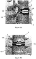
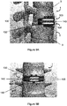
- FIGS 6A-15B Implantation of devices of the invention are illustrated in Figures 6A-15B .
- Figures 6A-9B show a two-plate non-contacting intervertebral disc replacement device according to embodiments of the invention, implanted between vertebra 1 that is superior to the replaced disc and vertebra 1' that is inferior to the replaced disc.
- Figures 6A-7B show implantation of the device having no linking material between plates 100 and 100', in which Figures 7A and 7B show magnets 130 and 130' within plates 100 and 100', respectively.
- Figures 8A-9B show implantation of the device having a linking material 140 present between plates 100 and 100', in which Figures 9A and 9B show magnets 130 and 130' within plates 100 and 100', respectively.
- Separation distance 135 between magnet 130 of superior plate 100 and magnet 130' of inferior plate 100', as well as the size of magnets 130 and 130', are chosen so that a sufficient force is generated to maintain separation of the two vertebral bodies to normal physiology height or the desired separation height and the separation distance allows a normal range of motion in all planes or the desired range of motion (see, e.g., Example 1).
- the two-plate non-contacting intervertebral disc replacement device is implanted such that distance 135 between magnet 130 and magnet 130' may be about 0.25 mm to about 20 mm, or about 0.5 mm to about 15 mm, or about 1 mm to about 10 mm.
- Figures 10A-11B show a two-plate contacting intervertebral disc replacement device according to embodiments of the invention, implanted between vertebra 1 that is superior to the replaced disc and vertebra 1' that is inferior to the replaced disc.
- Figures 11A and 11B show magnets 230 and 230' within plates 100 and 100', respectively. Separation distance 235 between magnet 230 of superior plate 200 and magnet 230' of inferior plate 200', as well as the size of magnets 230 and 230', are chosen to reduce the contact stress and subsequent wear and debris generated since wear and debris generation is a function of load (see, e.g., Example 1). The load across articulating surfaces 210 and 210' of two plates 200 and 200', respectively, can be reduced as much as desired.
- the two-plate contacting intervertebral disc replacement device is implanted such that distance 235 between magnet 230 and magnet 230' may be about 0.25 mm to about 20 mm, or about 0.5 mm to about 15 mm, or about 1 mm to about 10 mm.
- Figures 12A-15B show a two-plate-with-spacer contacting intervertebral disc replacement device according to embodiments of the invention, implanted between vertebra 1 that is superior to the replaced disc and vertebra 1' that is inferior to the replaced disc.
- Figures 13A and 13B show magnets 330 and 330' of plates 300 and 300', respectively, upon implantation of a device according to embodiments in which spacer 350 does not have any magnets. Separation distance 335 is between magnet 330 of superior plate 300 and magnet 330' of inferior plate.
- Figures 14A and 14B show magnets 330 and 330' of plates 300 and 300', respectively, and magnet 370 of spacer 350 upon implantation of a device according to embodiments in which spacer 350 contains a magnet that is not in association with either of its superior articulating surface 355 or its inferior articulating surface 360.
- Separation distance 336 is between magnet 330 of superior plate 300 and magnet 370 of spacer 350
- separation distance 336' is between magnet 330' of inferior plate 300' and magnet 370 of the spacer 350.
- Figures 15A and 15B show magnets 330 and 330' of plates 300 and 300', respectively, and magnets 371 and 371' of spacer's articulating surfaces 355 and 360, respectively, upon implantation of a device according to embodiments in which spacer 350 contains a magnet 371 in association with its superior articulating surface 355 and contains a magnet 371' in association with its inferior articulating surface 360.
- Separation distance 337 between magnet 330 of superior plate 300 and magnet 371 associated with superior articulating surface 355 of spacer 350, and separation distance 337' between magnet 330' of inferior plate 300' and magnet 371' associated with inferior articulating surface 360 of spacer 350, as well as the size of magnets 330, 330', 370, 371, and 371', are chosen to either reduce the contact stress and subsequent wear and debris generated since wear and debris generation is a function of load (see, e.g., Example 1), or to generate a sufficient attractive magnetic force.
- the load across the articulating surfaces can be reduced as much as desired.
- the two-plate-with-spacer contacting intervertebral disc replacement device is implanted such that distance 335, 336, 336', 337, and/or 337' may be about 0.25 mm to about 20 mm, or about 0.5 mm to about 15 mm, or about 1 mm to about 10 mm.
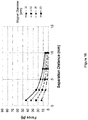
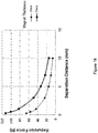
- JMAG utilizes finite element analysis to calculate the magnetic forces and fields. Briefly, the geometry of the magnets is loaded into the simulation software, and the magnetic strength and pole orientation is assigned when the simulation is performed.
- the analyses are designed to mimic the repulsion force generated between the magnet of a superior plate and the magnet of an inferior plate in a two-plate non-contacting intervertebral disc replacement device according to embodiments of the present invention; or between the magnet of a superior plate and the magnet of an inferior plate in a two-plate contacting intervertebral disc replacement device according to embodiments of the present invention; or between the magnet of a superior/inferior plate and the magnet of a spacer in a two-plate-with-spacer contacting intervertebral disc replacement device, according to embodiments of the present invention.
- the analyses considered magnet thicknesses of 3 mm and 5 mm; magnet diameters of 10 mm, 15 mm, 20 mm, and 25 mm; and separation distances of 0.25 mm, 0.5 mm, 1 mm, 3 mm, 5 mm, 7 mm, and 10 mm.
- a finite element analysis was conducted using JMAG as described in Example 1 to study how the magnetic repulsion forces are impacted by motion between the superior plate and inferior plate of an intervertebral disc replacement device.
- the analysis assesses the magnetic force field that is generated when the angle between the plates, and therefore the angle between the magnets that are embedded therein, is at 7 °.
- compositions can also consist essentially of, or consist of, any combination of the recited plates, spacers, and/or materials, unless described otherwise.
- methods are described as including particular steps, it is contemplated that the methods can also consist essentially of, or consist of, any combination of the recited steps, unless described otherwise.
- the invention illustratively disclosed herein suitably may be practiced in the absence of any element or step which is not specifically disclosed herein.
Landscapes
- Health & Medical Sciences (AREA)
- Engineering & Computer Science (AREA)
- Biomedical Technology (AREA)
- Neurology (AREA)
- Orthopedic Medicine & Surgery (AREA)
- Cardiology (AREA)
- Oral & Maxillofacial Surgery (AREA)
- Transplantation (AREA)
- Heart & Thoracic Surgery (AREA)
- Vascular Medicine (AREA)
- Life Sciences & Earth Sciences (AREA)
- Animal Behavior & Ethology (AREA)
- General Health & Medical Sciences (AREA)
- Public Health (AREA)
- Veterinary Medicine (AREA)
- Prostheses (AREA)
Applications Claiming Priority (2)
| Application Number | Priority Date | Filing Date | Title |
|---|---|---|---|
| US201862701518P | 2018-07-20 | 2018-07-20 | |
| US16/361,980 US11678995B2 (en) | 2018-07-20 | 2019-03-22 | Magnetic intervertebral disc replacement devices and methods thereof |
Publications (1)
| Publication Number | Publication Date |
|---|---|
| EP3597154A1 true EP3597154A1 (de) | 2020-01-22 |
Family
ID=67437912
Family Applications (1)
| Application Number | Title | Priority Date | Filing Date |
|---|---|---|---|
| EP19186887.6A Pending EP3597154A1 (de) | 2018-07-20 | 2019-07-18 | Magnetische bandscheibenersatzvorrichtungen |
Country Status (4)
| Country | Link |
|---|---|
| US (3) | US11678995B2 (de) |
| EP (1) | EP3597154A1 (de) |
| AU (3) | AU2019206035B2 (de) |
| CA (1) | CA3050368C (de) |
Cited By (2)
| Publication number | Priority date | Publication date | Assignee | Title |
|---|---|---|---|---|
| EP3875062A1 (de) * | 2020-03-05 | 2021-09-08 | Phoenyx Spinal Technologies Inc. | Ineinandergreifende wirbelsäulenbandscheibenprothese |
| US11291553B2 (en) | 2020-03-05 | 2022-04-05 | Phoenyx Spinal Technologies, Inc. | Interlocking spinal disc prosthetic |
Citations (12)
| Publication number | Priority date | Publication date | Assignee | Title |
|---|---|---|---|---|
| US6001130A (en) | 1994-11-14 | 1999-12-14 | Bryan; Vincent | Human spinal disc prosthesis with hinges |
| US20070179493A1 (en) * | 2006-01-13 | 2007-08-02 | Kim Richard C | Magnetic spinal implant device |
| US20070233251A1 (en) * | 2006-02-18 | 2007-10-04 | Abdou M S | Use of Magnetic Fields in Orthopedic Implants |
| US7491240B1 (en) | 2005-10-10 | 2009-02-17 | Donna Jean Carver | Artificial spinal disc replacement system and method |
| US7494508B2 (en) | 2004-04-28 | 2009-02-24 | Ldr Medical | Intervertebral disc prosthesis |
| US7766966B2 (en) | 2003-05-06 | 2010-08-03 | Aesculap Implant Systems, Llc | Artificial intervertebral disc |
| US8353964B2 (en) | 2010-11-04 | 2013-01-15 | Carpenter Clyde T | Anatomic total disc replacement |
| US8858635B2 (en) | 2004-02-04 | 2014-10-14 | Ldr Medical | Intervertebral disc prosthesis |
| US8911498B2 (en) | 2005-02-10 | 2014-12-16 | DePuy Synthes Products, LLC | Intervertebral prosthetic disc |
| US9173748B2 (en) | 2009-08-07 | 2015-11-03 | Ebi, Llc | Toroid-shaped spinal disc |
| US9566164B2 (en) | 2004-12-22 | 2017-02-14 | Ldr Medical | Intervertebral disc prosthesis |
| US9883945B2 (en) | 2008-03-11 | 2018-02-06 | Simplify Medical Pty Ltd | Artificial intervertebral disc with lower height |
Family Cites Families (60)
| Publication number | Priority date | Publication date | Assignee | Title |
|---|---|---|---|---|
| US4024588A (en) | 1974-10-04 | 1977-05-24 | Allo Pro A.G. | Artificial joints with magnetic attraction or repulsion |
| CH628803A5 (en) | 1978-05-12 | 1982-03-31 | Sulzer Ag | Implant insertable between adjacent vertebrae |
| US4332037A (en) | 1980-12-15 | 1982-06-01 | Hospital For Joint Disease Orthopaedic Institute | Artificial joint |
| US5879386A (en) | 1994-12-13 | 1999-03-09 | Jore; Matthew B. | Magnetic prosthetic system |
| US5595563A (en) * | 1995-09-05 | 1997-01-21 | Moisdon; Roger G. F. | Method and apparatus for maintaining the position of body parts |
| US5836948A (en) | 1997-01-02 | 1998-11-17 | Saint Francis Medical Technologies, Llc | Spine distraction implant and method |
| US6599321B2 (en) | 2000-06-13 | 2003-07-29 | Edward R. Hyde, Jr. | Magnetic array implant and prosthesis |
| US6387096B1 (en) | 2000-06-13 | 2002-05-14 | Edward R. Hyde, Jr. | Magnetic array implant and method of treating adjacent bone portions |
| FR2811540B1 (fr) | 2000-07-12 | 2003-04-25 | Spine Next Sa | Implant intervertebral amortissant |
| US6645251B2 (en) * | 2001-01-22 | 2003-11-11 | Smith & Nephew, Inc. | Surfaces and processes for wear reducing in orthopaedic implants |
| US20030187510A1 (en) | 2001-05-04 | 2003-10-02 | Hyde Edward R. | Mobile bearing prostheses |
| US20030195633A1 (en) | 2001-05-04 | 2003-10-16 | Hyde Edward R. | Magnetic array implant and prosthesis insert |
| US6695619B2 (en) | 2001-08-09 | 2004-02-24 | Oliver Brown-Wilkinson | Orthopaedic demonstration aid |
| US8029570B2 (en) | 2001-09-28 | 2011-10-04 | Mayo Foundation For Medical Education And Research | Implantation of magnets in bone to reduce contact pressure |
| EP2246012A2 (de) | 2002-03-30 | 2010-11-03 | Infinity Orthopaedics Company, Ltd. | Intervertebrale Vorrichtung |
| US20080027548A9 (en) * | 2002-04-12 | 2008-01-31 | Ferree Bret A | Spacerless artificial disc replacements |
| US6706068B2 (en) * | 2002-04-23 | 2004-03-16 | Bret A. Ferree | Artificial disc replacements with natural kinematics |
| US7204852B2 (en) | 2002-12-13 | 2007-04-17 | Spine Solutions, Inc. | Intervertebral implant, insertion tool and method of inserting same |
| EP2335651A1 (de) | 2003-07-11 | 2011-06-22 | DePuy Products, Inc. | In vivo Gelenkspalt-Messungsvorrichtung |
| GB2410189A (en) * | 2004-01-23 | 2005-07-27 | Corin Ltd | Intervertebral disc prosthesis |
| US20070100457A1 (en) | 2004-03-04 | 2007-05-03 | Hyde Edward R Jr | Paramagnetic liquid interface |
| US7637927B2 (en) | 2004-03-25 | 2009-12-29 | Hyde Jr Edward R | Transosseous spine core approach method implant and instrumentation |
| US7531002B2 (en) * | 2004-04-16 | 2009-05-12 | Depuy Spine, Inc. | Intervertebral disc with monitoring and adjusting capabilities |
| US20050251080A1 (en) | 2004-05-06 | 2005-11-10 | Hyde Edward R Jr | Magnetic vector control system |
| WO2006004848A1 (en) * | 2004-06-30 | 2006-01-12 | Synergy Disc Replacement, Inc. | Artificial spinal disc |
| US20060036323A1 (en) | 2004-08-03 | 2006-02-16 | Carl Alan L | Facet device and method |
| US8114158B2 (en) | 2004-08-03 | 2012-02-14 | Kspine, Inc. | Facet device and method |
| US20060079897A1 (en) | 2004-09-29 | 2006-04-13 | Harrison Michael R | Apparatus and methods for magnetic alteration of anatomical features |
| US8142454B2 (en) | 2004-09-29 | 2012-03-27 | The Regents Of The University Of California, San Francisco | Apparatus and method for magnetic alteration of anatomical features |
| US8425559B2 (en) | 2004-10-20 | 2013-04-23 | Vertiflex, Inc. | Systems and methods for posterior dynamic stabilization of the spine |
| US7578848B2 (en) * | 2005-03-03 | 2009-08-25 | Cervical Xpand, Llc | Intervertebral stabilizer |
| US7811328B2 (en) | 2005-04-29 | 2010-10-12 | Warsaw Orthopedic, Inc. | System, device and methods for replacing the intervertebral disc with a magnetic or electromagnetic prosthesis |
| US20060247623A1 (en) | 2005-04-29 | 2006-11-02 | Sdgi Holdings, Inc. | Local delivery of an active agent from an orthopedic implant |
| US20060282166A1 (en) * | 2005-06-09 | 2006-12-14 | Sdgi Holdings, Inc. | Compliant porous coating |
| WO2007024990A2 (en) | 2005-08-23 | 2007-03-01 | Kim Richard C | Expandable implant device with interchangeable spacer |
| US8828061B2 (en) | 2007-03-19 | 2014-09-09 | Us Spine, Inc. | Vertebral stabilization devices and associated surgical methods |
| US9757585B2 (en) | 2007-06-05 | 2017-09-12 | P Tech, Llc | Magnetic joint implant |
| US20100121381A1 (en) | 2008-06-09 | 2010-05-13 | Springback, Inc. | Surgical method and apparatus for treating spinal stenosis and stabilization of vertebrae |
| JP5542132B2 (ja) | 2008-06-19 | 2014-07-09 | モキシメッド インコーポレイテッド | 関節支持を提供するための移植可能なブレース |
| US20100030337A1 (en) | 2008-08-04 | 2010-02-04 | Nasser Ani | Spine Surgery Technique And System |
| US20100036493A1 (en) | 2008-08-05 | 2010-02-11 | Simon Jerome H | Magnetic cushioning devices |
| US8128699B2 (en) * | 2009-03-13 | 2012-03-06 | Warsaw Orthopedic, Inc. | Spinal implant and methods of implantation and treatment |
| US9622792B2 (en) | 2009-04-29 | 2017-04-18 | Nuvasive Specialized Orthopedics, Inc. | Interspinous process device and method |
| AU2010270915A1 (en) | 2009-06-23 | 2011-12-15 | Osteomed | Bone tissue clamp |
| US8118815B2 (en) * | 2009-07-24 | 2012-02-21 | OrthAlign, Inc. | Systems and methods for joint replacement |
| WO2012174485A1 (en) | 2011-06-17 | 2012-12-20 | Jcbd, Llc | Sacroiliac joint implant system |
| US8388656B2 (en) | 2010-02-04 | 2013-03-05 | Ebi, Llc | Interspinous spacer with deployable members and related method |
| US8449615B2 (en) | 2010-04-18 | 2013-05-28 | F.I.S.H., Llc | Intervertebral implants having hydromagnetic joints |
| US8454692B2 (en) | 2010-04-18 | 2013-06-04 | F.I.S.H., Llc | Systems and devices having hydromagnetic joints and hydromagnetic springs |
| US8734488B2 (en) | 2010-08-09 | 2014-05-27 | Ellipse Technologies, Inc. | Maintenance feature in magnetic implant |
| WO2012103254A2 (en) | 2011-01-25 | 2012-08-02 | Nuvasive, Inc. | Spinal implants for rotationally adjusting vertebrae |
| US10660674B2 (en) | 2012-07-17 | 2020-05-26 | Gomboc, LLC | Magnetically levitated spinous process implants and methods thereof |
| US8801796B2 (en) | 2012-12-31 | 2014-08-12 | Richard A. Rogachefsky | Bone prosthesis for maintaining joint operation in complex joints |
| US20150005886A1 (en) | 2013-07-01 | 2015-01-01 | John Michael Pinneo | Prosthetic Joints |
| GB201416867D0 (en) * | 2014-09-24 | 2014-11-05 | Fitzbionics Ltd | A prosthetic intervertebral disc joint assembly |
| US9289311B1 (en) | 2015-06-12 | 2016-03-22 | Amendia, Inc. | Artificial disc with shunt enhanced magnetic fields |
| US9408714B1 (en) * | 2015-06-12 | 2016-08-09 | Amendia, Inc. | Artificial disc |
| US20180014838A1 (en) | 2016-06-29 | 2018-01-18 | Omega Innovative Technologies, Llc | Magnetic implant for joint fixation and method |
| US10702320B2 (en) | 2017-07-21 | 2020-07-07 | Christopher A. Archbold | Magnetic core bone screw |
| US10555787B2 (en) | 2017-08-15 | 2020-02-11 | Gomboc, LLC | Internal magnetic traction device for the cervical seine |
-
2019
- 2019-03-22 US US16/361,980 patent/US11678995B2/en active Active
- 2019-07-17 AU AU2019206035A patent/AU2019206035B2/en not_active Ceased
- 2019-07-18 EP EP19186887.6A patent/EP3597154A1/de active Pending
- 2019-07-19 CA CA3050368A patent/CA3050368C/en active Active
-
2021
- 2021-02-18 AU AU2021201064A patent/AU2021201064B2/en not_active Ceased
-
2022
- 2022-10-06 AU AU2022246415A patent/AU2022246415B2/en not_active Ceased
-
2023
- 2023-01-20 US US18/099,505 patent/US20230157834A1/en active Pending
- 2023-01-20 US US18/099,486 patent/US20230181328A1/en active Pending
Patent Citations (12)
| Publication number | Priority date | Publication date | Assignee | Title |
|---|---|---|---|---|
| US6001130A (en) | 1994-11-14 | 1999-12-14 | Bryan; Vincent | Human spinal disc prosthesis with hinges |
| US7766966B2 (en) | 2003-05-06 | 2010-08-03 | Aesculap Implant Systems, Llc | Artificial intervertebral disc |
| US8858635B2 (en) | 2004-02-04 | 2014-10-14 | Ldr Medical | Intervertebral disc prosthesis |
| US7494508B2 (en) | 2004-04-28 | 2009-02-24 | Ldr Medical | Intervertebral disc prosthesis |
| US9566164B2 (en) | 2004-12-22 | 2017-02-14 | Ldr Medical | Intervertebral disc prosthesis |
| US8911498B2 (en) | 2005-02-10 | 2014-12-16 | DePuy Synthes Products, LLC | Intervertebral prosthetic disc |
| US7491240B1 (en) | 2005-10-10 | 2009-02-17 | Donna Jean Carver | Artificial spinal disc replacement system and method |
| US20070179493A1 (en) * | 2006-01-13 | 2007-08-02 | Kim Richard C | Magnetic spinal implant device |
| US20070233251A1 (en) * | 2006-02-18 | 2007-10-04 | Abdou M S | Use of Magnetic Fields in Orthopedic Implants |
| US9883945B2 (en) | 2008-03-11 | 2018-02-06 | Simplify Medical Pty Ltd | Artificial intervertebral disc with lower height |
| US9173748B2 (en) | 2009-08-07 | 2015-11-03 | Ebi, Llc | Toroid-shaped spinal disc |
| US8353964B2 (en) | 2010-11-04 | 2013-01-15 | Carpenter Clyde T | Anatomic total disc replacement |
Cited By (3)
| Publication number | Priority date | Publication date | Assignee | Title |
|---|---|---|---|---|
| EP3875062A1 (de) * | 2020-03-05 | 2021-09-08 | Phoenyx Spinal Technologies Inc. | Ineinandergreifende wirbelsäulenbandscheibenprothese |
| US11291553B2 (en) | 2020-03-05 | 2022-04-05 | Phoenyx Spinal Technologies, Inc. | Interlocking spinal disc prosthetic |
| US12090059B2 (en) | 2020-03-05 | 2024-09-17 | Bret Michael Berry | Interlocking spinal disc prosthetic |
Also Published As
| Publication number | Publication date |
|---|---|
| AU2019206035B2 (en) | 2020-11-19 |
| CA3050368C (en) | 2024-06-11 |
| AU2021201064B2 (en) | 2022-07-07 |
| AU2019206035A1 (en) | 2020-02-06 |
| AU2021201064A1 (en) | 2021-03-11 |
| AU2022246415B2 (en) | 2024-08-01 |
| US20230157834A1 (en) | 2023-05-25 |
| US20230181328A1 (en) | 2023-06-15 |
| CA3050368A1 (en) | 2020-01-20 |
| AU2022246415A1 (en) | 2022-11-03 |
| US11678995B2 (en) | 2023-06-20 |
| US20200022818A1 (en) | 2020-01-23 |
Similar Documents
| Publication | Publication Date | Title |
|---|---|---|
| CA2495373C (en) | Controlled artificial intervertebral disc implant | |
| Eijkelkamp et al. | Requirements for an artificial intervertebral disc | |
| EP2299940B1 (de) | Bandscheibenprothese mit eingeschränkter bewegung | |
| Bono et al. | History and evolution of disc replacement | |
| US20050085909A1 (en) | Semi-constrained and mobile-bearing disc prosthesis | |
| US20230181328A1 (en) | Magnetic intervertebral disc replacement devices and methods thereof | |
| KR20060056265A (ko) | 제어된 인공 추간판 임플란트 | |
| EP3082653A1 (de) | Zwischenwirbeldistanzstück mit dynamischer förderung des knochenwachstums | |
| EP2461771A2 (de) | Ringförmige bandscheibe | |
| ZA200501542B (en) | Controlled artificial intervertebral disc implant | |
| Geisler | The CHARITE Artificial Disc: Design History, FDA IDE Study, Results, and Surgical Technique | |
| Gloria et al. | Composite materials for spinal implants | |
| Eijkelkamp | On the development of an artificial intervertebral disc | |
| US10258482B1 (en) | Artificial intervertebral implant | |
| Muckley et al. | Intervertebral disc and nucleus replacement devices and instrumentations | |
| US20250248824A1 (en) | Intervertebral implant having variable height serrations | |
| EP4420637A1 (de) | Künstliche bandscheibe | |
| Afify et al. | Comparative Biomechanical Analysis of Lumbar Disc Arthroplasty using Finite Element Modeling | |
| Rotaru et al. | Total disc prostheses for lumbar spine: a systematic review of the literature | |
| Khoo et al. | Lumbar disc replacement | |
| Livingston et al. | ME 598-Orthopedic Biomechanics December 12, 2018 | |
| Banerjee et al. | Biomechanical Remedies for Degeneration of Cervical Spine—A Review of Literature | |
| Büttner-Janz et al. | Future Innovations | |
| Wang et al. | Advances in biomaterials that led to the artificial disc |
Legal Events
| Date | Code | Title | Description |
|---|---|---|---|
| PUAI | Public reference made under article 153(3) epc to a published international application that has entered the european phase |
Free format text: ORIGINAL CODE: 0009012 |
|
| STAA | Information on the status of an ep patent application or granted ep patent |
Free format text: STATUS: THE APPLICATION HAS BEEN PUBLISHED |
|
| AK | Designated contracting states |
Kind code of ref document: A1 Designated state(s): AL AT BE BG CH CY CZ DE DK EE ES FI FR GB GR HR HU IE IS IT LI LT LU LV MC MK MT NL NO PL PT RO RS SE SI SK SM TR |
|
| AX | Request for extension of the european patent |
Extension state: BA ME |
|
| STAA | Information on the status of an ep patent application or granted ep patent |
Free format text: STATUS: REQUEST FOR EXAMINATION WAS MADE |
|
| 17P | Request for examination filed |
Effective date: 20200722 |
|
| RBV | Designated contracting states (corrected) |
Designated state(s): AL AT BE BG CH CY CZ DE DK EE ES FI FR GB GR HR HU IE IS IT LI LT LU LV MC MK MT NL NO PL PT RO RS SE SI SK SM TR |
|
| STAA | Information on the status of an ep patent application or granted ep patent |
Free format text: STATUS: EXAMINATION IS IN PROGRESS |
|
| 17Q | First examination report despatched |
Effective date: 20221124 |