EP3597231A1 - Systèmes et procédés de détection d'inertie pour diagnostics vad et commande en boucle fermée - Google Patents
Systèmes et procédés de détection d'inertie pour diagnostics vad et commande en boucle fermée Download PDFInfo
- Publication number
- EP3597231A1 EP3597231A1 EP19186464.4A EP19186464A EP3597231A1 EP 3597231 A1 EP3597231 A1 EP 3597231A1 EP 19186464 A EP19186464 A EP 19186464A EP 3597231 A1 EP3597231 A1 EP 3597231A1
- Authority
- EP
- European Patent Office
- Prior art keywords
- heart
- vad
- patient
- controller
- impeller
- Prior art date
- Legal status (The legal status is an assumption and is not a legal conclusion. Google has not performed a legal analysis and makes no representation as to the accuracy of the status listed.)
- Granted
Links
Images




Classifications
-
- A—HUMAN NECESSITIES
- A61—MEDICAL OR VETERINARY SCIENCE; HYGIENE
- A61M—DEVICES FOR INTRODUCING MEDIA INTO, OR ONTO, THE BODY; DEVICES FOR TRANSDUCING BODY MEDIA OR FOR TAKING MEDIA FROM THE BODY; DEVICES FOR PRODUCING OR ENDING SLEEP OR STUPOR
- A61M60/00—Blood pumps; Devices for mechanical circulatory actuation; Balloon pumps for circulatory assistance
- A61M60/10—Location thereof with respect to the patient's body
- A61M60/122—Implantable pumps or pumping devices, i.e. the blood being pumped inside the patient's body
- A61M60/126—Implantable pumps or pumping devices, i.e. the blood being pumped inside the patient's body implantable via, into, inside, in line, branching on, or around a blood vessel
- A61M60/148—Implantable pumps or pumping devices, i.e. the blood being pumped inside the patient's body implantable via, into, inside, in line, branching on, or around a blood vessel in line with a blood vessel using resection or like techniques, e.g. permanent endovascular heart assist devices
-
- A—HUMAN NECESSITIES
- A61—MEDICAL OR VETERINARY SCIENCE; HYGIENE
- A61M—DEVICES FOR INTRODUCING MEDIA INTO, OR ONTO, THE BODY; DEVICES FOR TRANSDUCING BODY MEDIA OR FOR TAKING MEDIA FROM THE BODY; DEVICES FOR PRODUCING OR ENDING SLEEP OR STUPOR
- A61M60/00—Blood pumps; Devices for mechanical circulatory actuation; Balloon pumps for circulatory assistance
- A61M60/10—Location thereof with respect to the patient's body
- A61M60/122—Implantable pumps or pumping devices, i.e. the blood being pumped inside the patient's body
- A61M60/165—Implantable pumps or pumping devices, i.e. the blood being pumped inside the patient's body implantable in, on, or around the heart
- A61M60/178—Implantable pumps or pumping devices, i.e. the blood being pumped inside the patient's body implantable in, on, or around the heart drawing blood from a ventricle and returning the blood to the arterial system via a cannula external to the ventricle, e.g. left or right ventricular assist devices
-
- A—HUMAN NECESSITIES
- A61—MEDICAL OR VETERINARY SCIENCE; HYGIENE
- A61M—DEVICES FOR INTRODUCING MEDIA INTO, OR ONTO, THE BODY; DEVICES FOR TRANSDUCING BODY MEDIA OR FOR TAKING MEDIA FROM THE BODY; DEVICES FOR PRODUCING OR ENDING SLEEP OR STUPOR
- A61M60/00—Blood pumps; Devices for mechanical circulatory actuation; Balloon pumps for circulatory assistance
- A61M60/10—Location thereof with respect to the patient's body
- A61M60/122—Implantable pumps or pumping devices, i.e. the blood being pumped inside the patient's body
- A61M60/165—Implantable pumps or pumping devices, i.e. the blood being pumped inside the patient's body implantable in, on, or around the heart
-
- A—HUMAN NECESSITIES
- A61—MEDICAL OR VETERINARY SCIENCE; HYGIENE
- A61M—DEVICES FOR INTRODUCING MEDIA INTO, OR ONTO, THE BODY; DEVICES FOR TRANSDUCING BODY MEDIA OR FOR TAKING MEDIA FROM THE BODY; DEVICES FOR PRODUCING OR ENDING SLEEP OR STUPOR
- A61M60/00—Blood pumps; Devices for mechanical circulatory actuation; Balloon pumps for circulatory assistance
- A61M60/20—Type thereof
- A61M60/205—Non-positive displacement blood pumps
- A61M60/216—Non-positive displacement blood pumps including a rotating member acting on the blood, e.g. impeller
-
- A—HUMAN NECESSITIES
- A61—MEDICAL OR VETERINARY SCIENCE; HYGIENE
- A61M—DEVICES FOR INTRODUCING MEDIA INTO, OR ONTO, THE BODY; DEVICES FOR TRANSDUCING BODY MEDIA OR FOR TAKING MEDIA FROM THE BODY; DEVICES FOR PRODUCING OR ENDING SLEEP OR STUPOR
- A61M60/00—Blood pumps; Devices for mechanical circulatory actuation; Balloon pumps for circulatory assistance
- A61M60/20—Type thereof
- A61M60/205—Non-positive displacement blood pumps
- A61M60/216—Non-positive displacement blood pumps including a rotating member acting on the blood, e.g. impeller
- A61M60/226—Non-positive displacement blood pumps including a rotating member acting on the blood, e.g. impeller the blood flow through the rotating member having mainly radial components
- A61M60/232—Centrifugal pumps
-
- A—HUMAN NECESSITIES
- A61—MEDICAL OR VETERINARY SCIENCE; HYGIENE
- A61M—DEVICES FOR INTRODUCING MEDIA INTO, OR ONTO, THE BODY; DEVICES FOR TRANSDUCING BODY MEDIA OR FOR TAKING MEDIA FROM THE BODY; DEVICES FOR PRODUCING OR ENDING SLEEP OR STUPOR
- A61M60/00—Blood pumps; Devices for mechanical circulatory actuation; Balloon pumps for circulatory assistance
- A61M60/40—Details relating to driving
- A61M60/403—Details relating to driving for non-positive displacement blood pumps
- A61M60/422—Details relating to driving for non-positive displacement blood pumps the force acting on the blood contacting member being electromagnetic, e.g. using canned motor pumps
-
- A—HUMAN NECESSITIES
- A61—MEDICAL OR VETERINARY SCIENCE; HYGIENE
- A61M—DEVICES FOR INTRODUCING MEDIA INTO, OR ONTO, THE BODY; DEVICES FOR TRANSDUCING BODY MEDIA OR FOR TAKING MEDIA FROM THE BODY; DEVICES FOR PRODUCING OR ENDING SLEEP OR STUPOR
- A61M60/00—Blood pumps; Devices for mechanical circulatory actuation; Balloon pumps for circulatory assistance
- A61M60/50—Details relating to control
- A61M60/508—Electronic control means, e.g. for feedback regulation
- A61M60/515—Regulation using real-time patient data
-
- A—HUMAN NECESSITIES
- A61—MEDICAL OR VETERINARY SCIENCE; HYGIENE
- A61M—DEVICES FOR INTRODUCING MEDIA INTO, OR ONTO, THE BODY; DEVICES FOR TRANSDUCING BODY MEDIA OR FOR TAKING MEDIA FROM THE BODY; DEVICES FOR PRODUCING OR ENDING SLEEP OR STUPOR
- A61M60/00—Blood pumps; Devices for mechanical circulatory actuation; Balloon pumps for circulatory assistance
- A61M60/50—Details relating to control
- A61M60/508—Electronic control means, e.g. for feedback regulation
- A61M60/538—Regulation using real-time blood pump operational parameter data, e.g. motor current
-
- A—HUMAN NECESSITIES
- A61—MEDICAL OR VETERINARY SCIENCE; HYGIENE
- A61M—DEVICES FOR INTRODUCING MEDIA INTO, OR ONTO, THE BODY; DEVICES FOR TRANSDUCING BODY MEDIA OR FOR TAKING MEDIA FROM THE BODY; DEVICES FOR PRODUCING OR ENDING SLEEP OR STUPOR
- A61M60/00—Blood pumps; Devices for mechanical circulatory actuation; Balloon pumps for circulatory assistance
- A61M60/80—Constructional details other than related to driving
- A61M60/802—Constructional details other than related to driving of non-positive displacement blood pumps
- A61M60/81—Pump housings
- A61M60/816—Sensors arranged on or in the housing, e.g. ultrasonic flow sensors
-
- A—HUMAN NECESSITIES
- A61—MEDICAL OR VETERINARY SCIENCE; HYGIENE
- A61M—DEVICES FOR INTRODUCING MEDIA INTO, OR ONTO, THE BODY; DEVICES FOR TRANSDUCING BODY MEDIA OR FOR TAKING MEDIA FROM THE BODY; DEVICES FOR PRODUCING OR ENDING SLEEP OR STUPOR
- A61M2205/00—General characteristics of the apparatus
- A61M2205/33—Controlling, regulating or measuring
- A61M2205/3331—Pressure; Flow
- A61M2205/3334—Measuring or controlling the flow rate
-
- A—HUMAN NECESSITIES
- A61—MEDICAL OR VETERINARY SCIENCE; HYGIENE
- A61M—DEVICES FOR INTRODUCING MEDIA INTO, OR ONTO, THE BODY; DEVICES FOR TRANSDUCING BODY MEDIA OR FOR TAKING MEDIA FROM THE BODY; DEVICES FOR PRODUCING OR ENDING SLEEP OR STUPOR
- A61M2205/00—General characteristics of the apparatus
- A61M2205/50—General characteristics of the apparatus with microprocessors or computers
-
- A—HUMAN NECESSITIES
- A61—MEDICAL OR VETERINARY SCIENCE; HYGIENE
- A61M—DEVICES FOR INTRODUCING MEDIA INTO, OR ONTO, THE BODY; DEVICES FOR TRANSDUCING BODY MEDIA OR FOR TAKING MEDIA FROM THE BODY; DEVICES FOR PRODUCING OR ENDING SLEEP OR STUPOR
- A61M2210/00—Anatomical parts of the body
- A61M2210/12—Blood circulatory system
- A61M2210/125—Heart
Definitions
- Ventricular assist devices are used for both short-term (i.e., days, months) and long-term blood circulation assistance (i.e., years or a lifetime) where a patient's heart is incapable of providing adequate circulation, commonly referred to as heart failure or congestive heart failure.
- heart failure i.e., congestive heart failure
- Heart Association more than five million Americans are living with heart failure, with about 670,000 new cases diagnosed every year. People with heart failure often have shortness of breath and fatigue. Years of living with blocked arteries and/or high blood pressure can leave a heart too weak to pump enough blood to the body. As symptoms worsen, advanced heart failure develops.
- a patient suffering from heart failure may use a VAD while awaiting a heart transplant or as a long term destination therapy.
- a patient may also use a VAD while recovering from heart surgery.
- a VAD can supplement a weak heart (i.e., partial support) or can effectively replace the natural heart's function.
- Blood circulation assist systems and related methods employ a ventricular assist device (VAD) that includes an accelerometer to measure accelerations of the VAD for use in controlling operation of the VAD, generating patient monitoring data, and/or generating VAD monitoring data.
- VAD ventricular assist device
- the measured accelerations are processed to measure patient activity level, which is used to control the output level of the VAD based on the patient activity level.
- the output level of the VAD can be increased in response to an increase in the patient activity level and decreased in response to a decrease in the patient activity level.
- the measured accelerations are processed to track the patient's cardiac cycle timing, which is used to control variation in output of the VAD in synchronization with the patient's cardiac cycle timing.
- the measured accelerations are used to generate patient monitoring data and/or VAD monitoring data.
- the circulatory support provided is better tailored to the needs of the patient, and may thereby produce better results. Additionally, the availability of the patient monitoring data and/or the VAD tracking data may enable increased ability to diagnose patient health issues and/or VAD operational problems.
- a blood circulation assist system includes a ventricular assist device (VAD) and a controller.
- the VAD is coupleable to a heart of a patient to pump blood from a ventricle of the heart into a blood vessel of the patient.
- the VAD includes an impeller, a motor stator operable to rotate the impeller, and an accelerometer generating an accelerometer output indicative of accelerations of the VAD.
- the controller controls operation of the motor stator to control rotational speed of the impeller based on the accelerometer output.
- the controller controls variation in output of the VAD in synch with the cardiac cycle timing of the heart.
- the controller processes the accelerometer output to detect cardiac cycle timing of the heart.
- the cardiac cycle timing can include a heart rate of the patient and a time of occurrence for each of one or more cardiac cycle events for the heart.
- the controller can vary the rotational speed of the impeller in sync with the cardiac cycle timing. In some embodiments, the controller varies the rotational speed to increase a rate at which the VAD pumps blood from the ventricle to the blood vessel during ventricular systole.
- the controller detects the cardiac cycle timing by measuring heart wall motion.
- the controller can process the accelerometer output to measure motion of a heart wall of the heart to which the VAD is attached.
- the controller can detect timing of ventricular systole of the heart based on the motion of the heart wall.
- the controller detects the cardiac cycle timing based on at least one heart sound.
- the controller can process the accelerometer output to detect a time of occurrence of at least one heart sound.
- the controller can detect timing of ventricular systole of the heart based on the time of occurrence of the at least one heart sound.
- the at least one heart sound includes a sound of closure of the atrioventricular valves of the heart, and/or a sound of closure of the semilunar valves of the heart.
- the controller detects the cardiac cycle timing by detecting variation in drive current supplied to the VAD. For example, in some embodiments the controller: (a) controls the motor stator to rotate the impeller at a constant speed throughout at least one complete cardiac cycle of the heart, (b) monitors drive current supplied to the motor stator to rotate the impeller at the constant speed, and (c) processes the monitored drive current to detect the cardiac cycle timing of the heart. In some embodiments, the controller varies the rotational speed of the impeller during ventricular systole of the heart to increase a rate at which the VAD pumps blood from the ventricle to the blood vessel.
- the controller synchronizes the output of the VAD with a target cardiac cycle based on detected timing of one or more previous cardiac cycles. For example, in some embodiments the controller varies the rotational speed of the impeller over a target cardiac cycle of the heart based on detected timing of one or more cardiac cycles of the heart that occur prior to the target cardiac cycle.
- the controller synchronizes the output of the VAD with a target cardiac cycle based on detected timing of the target cardiac cycle. For example, in some embodiments, the controller varies the rotational speed of the impeller over a target cardiac cycle of the heart based on detected timing of the target cardiac cycle.
- the controller controls output of the VAD based on an activity level of the patient. For example, in some embodiments, the controller: (a) processes the accelerometer output to measure an activity level of the patient, and (b) controls the rotational speed of the impeller based on the activity level. In some embodiments, the controller: (a) processes the accelerometer output to measure a respiration rate for the patient and/or a diaphragm contraction for the patient, and (b) bases the activity level on the respiration rate and/or the diaphragm contraction. In some embodiments, the controller: (a) processes the accelerometer output to measure a contraction of the ventricle, and (b) bases the activity level on the contraction of the ventricle.
- the controller (a) processes the accelerometer output to measure a heart rate of the patient, and (b) bases the activity level on the heart rate. In some embodiments, the controller: (a) processes the accelerometer output to detect an orientation of the patient, and (b) bases the activity level on the orientation of the patient.
- the activity level of the patient, on which basis the controller controls the rotational speed of the impeller can be defined to be any suitable function of one or more of the respiration rate of the patient, the diaphragm contraction for the patient, the contraction of the ventricle, the heart rate of the patient, and the orientation of the patient.
- the controller can be disposed in any suitable location.
- the controller is disposed within a housing of the VAD.
- the blood circulation assist system further includes an external control unit operatively coupled with the VAD, and the controller is disposed within a housing of the external control unit.
- the accelerometer output is indicative of accelerations of the VAD relative to three different axes.
- a blood circulation assist system in another aspect, includes a ventricular assist device (VAD) and a controller.
- VAD ventricular assist device
- the VAD is coupleable to a heart of a patient to pump blood from a ventricle of the heart into a blood vessel of the patient.
- the VAD includes an accelerometer generating an accelerometer output indicative of accelerations of the VAD.
- the controller processes the accelerometer output to generate patient monitoring data for the patient indicative of one or more physiological parameters of the patient.
- the patient monitoring data can include any suitable data that can be generated by processing the accelerometer output.
- the patient monitoring data includes orientations of the patient and/or the VAD.
- the patient monitoring data includes activity levels of the patient.
- the patient monitoring data includes respiration rates and/or diaphragm contraction amplitudes.
- the patient monitoring data includes contraction amplitudes for the ventricle.
- the patient monitoring data includes heart rates of the patient.
- the patient monitoring data is indicative of whether a blood clot has passed through the VAD during an acquisition time period for the patient monitoring data.
- the patient monitoring data is indicative of whether the patient suffers from aortic insufficiency.
- the patient monitoring data is indicative of whether arrhythmia has occurred during an acquisition time period for the patient monitoring data.
- the patient monitoring data is indicative of whether the VAD has migrated/shifted position and/or the heart has remodeled.
- the blood circulation assist system includes a memory device in which the patient monitoring data is stored.
- the patient monitoring data stored in the memory device is accessible for subsequent display and/or processing.
- a blood circulation assist system in another aspect, includes a ventricular assist device (VAD) and a controller.
- VAD ventricular assist device
- the VAD is coupleable to a heart of a patient to pump blood from a ventricle of the heart into a blood vessel of the patient.
- the VAD includes an accelerometer generating an accelerometer output indicative of accelerations of the VAD.
- the controller processes the accelerometer output to generate VAD monitoring data indicative of one or more operational parameters of the VAD.
- the VAD monitoring data can include any suitable data that can be generated by processing the accelerometer output.
- the VAD includes an impeller and a motor stator operable to rotate the impeller
- the VAD monitoring data is indicative of vibrations of the impeller.
- the VAD monitoring data is indicative of whether a suction event has occurred during an acquisition time period for the VAD monitoring data.
- the blood circulation assist system includes a memory device in which the VAD monitoring data is stored.
- the VAD monitoring data stored in the memory device is accessible for subsequent display and/or processing.
- FIG. 1 is an illustration of a mechanical circulatory support system 10 that includes a ventricular assist device (VAD) 14 implanted in a patient's body 12.
- the mechanical circulatory support system 10 includes the VAD 14, a ventricular cuff 16, an outflow cannula 18, an external system controller 20, and power sources 22.
- a VAD 14 can be attached to an apex of the left ventricle, as illustrated, or the right ventricle, or a separate VAD can be attached to each of the ventricles of the heart 24.
- the VAD 14 can be capable of pumping the entire flow of blood delivered to the left ventricle from the pulmonary circulation (i.e., up to 10 liters per minute).
- the VAD 14 can be attached to the heart 24 via the ventricular cuff 16, which can be sewn to the heart 24 and coupled to the VAD 14.
- the output of the VAD 14 connects to the ascending aorta via the outflow cannula 18 so that the VAD 14 effectively diverts blood from the left ventricle and propels it to the aorta for circulation through the rest of the patient's vascular system.
- FIG. 1 illustrates the mechanical circulatory support system 10 during battery 22 powered operation.
- a driveline 26 that exits through the patient's abdomen 28 connects the VAD 14 to the external system controller 20, which monitors system 10 operation.
- Related controller systems applicable to the present invention are described in greater detail below and in U.S. Patent Nos. 5,888,242 , 6,991,595 , 8,323,174 , 8,449,444 , 8,506,471 , 8,597,350 , and 8,657,733 , EP 1812094 , and U.S. Patent Publication Nos. 2005/0071001 and 2013/0314047 , all of which are incorporated herein by reference for all purposes in their entirety.
- the system 10 can be powered by either one, two, or more batteries 22.
- system controller 20 and power source 22 are illustrated outside/external to the patient body 12, the driveline 26, the system controller 20 and/or the power source 22 can be partially or fully implantable within the patient 12, as separate components or integrated with the VAD 14. Examples of such modifications are further described in U.S. Patent No. 8,562,508 and U.S. Patent No. 9,079,043 , all of which are incorporated herein by reference for all purposes in their entirety.
- the VAD 14 has a circular shaped housing 110 and is shown implanted within the patient 12 with a first face 111 of the housing 110 positioned against the patient's heart 24 and a second face 113 of the housing 110 facing away from the heart 24.
- the first face 111 of the housing 110 includes an inlet cannula 112 extending into the left ventricle LV of the heart 24.
- the second face 113 of the housing 110 has a chamfered edge 114 to avoid irritating other tissue that may come into contact with the VAD 14, such as the patient's diaphragm.
- a stator 120 and electronics 130 of the VAD 14 are positioned on the inflow side of the housing toward first face 111, and a rotor 140 of the VAD 14 is positioned along the second face 113.
- This positioning of the stator 120, electronics 130, and rotor 140 permits the edge 114 to be chamfered along the contour of the rotor 140, as illustrated in at least FIG. 3 and FIG. 4 , for example.
- the VAD 14 includes a dividing wall 115 within the housing 110 defining a blood flow conduit 103.
- the blood flow conduit 103 extends from an inlet opening 101 of the inlet cannula 112 through the stator 120 to an outlet opening 105 defined by the housing 110.
- the rotor 140 is positioned within the blood flow conduit 103.
- the stator 120 is disposed circumferentially about a first portion 140a of the rotor 140, for example about a permanent magnet 141.
- the stator 120 is also positioned relative to the rotor 140 such that, in use, blood flows within the blood flow conduit 103 through the stator 120 before reaching the rotor 140.
- the permanent magnet 141 has a permanent magnetic north pole N and a permanent magnetic south pole S for combined active and passive magnetic levitation of the rotor 140 and for rotation of the rotor 140.
- the rotor 140 also has a second portion 140b that includes impeller blades 143.
- the impeller blades 143 are located within a volute 107 of the blood flow conduit such that the impeller blades 143 are located proximate to the second face 113 of the housing 110.
- the puck-shaped housing 110 further includes a peripheral wall 116 that extends between the first face 111 and a removable cap 118.
- the peripheral wall 116 is formed as a hollow circular cylinder having a width W between opposing portions of the peripheral wall 116.
- the housing 110 also has a thickness T between the first face 111 and the second face 113 that is less than the width W.
- the thickness T is from about 0.5 inches to about 1.5 inches, and the width W is from about 1 inch to about 4 inches.
- the width W can be approximately 2 inches, and the thickness T can be approximately 1 inch.
- the peripheral wall 116 encloses an internal compartment 117 that surrounds the dividing wall 115 and the blood flow conduit 103, with the stator 120 and the electronics 130 disposed in the internal compartment 117 about the dividing wall 115.
- the removable cap 118 includes the second face 113, the chamfered edge 114, and defines the outlet opening 105.
- the cap 118 can be threadedly engaged with the peripheral wall 116 to seal the cap 118 in engagement with the peripheral wall 116.
- the cap 118 includes an inner surface 118a of the cap 118 that defines the volute 107 that is in fluid communication with the outlet opening 105.
- the electronics 130 are positioned adjacent to the first face 111 and the stator 120 is positioned adjacent to the electronics 130 on an opposite side of the electronics 130 from the first face 111.
- the electronics 130 include circuit boards 131 and various components carried on the circuit boards 131 to control the operation of the VAD 14 (e.g., magnetic levitation and/or drive of the rotor) by controlling the electrical supply to the stator 120.
- the housing 110 is configured to receive the circuit boards 131 within the internal compartment 117 generally parallel to the first face 111 for efficient use of the space within the internal compartment 117.
- the circuit boards also extend radially-inward towards the dividing wall 115 and radially-outward towards the peripheral wall 116.
- the internal compartment 117 is generally sized no larger than necessary to accommodate the circuit boards 131, and space for heat dissipation, material expansion, potting materials, and/or other elements used in installing the circuit boards 131.
- the external shape of the housing 110 proximate the first face 111 generally fits the shape of the circuits boards 131 closely to provide external dimensions that are not much greater than the dimensions of the circuit boards 131.
- the stator 120 includes a back iron 121 and pole pieces 123a-123f arranged at intervals around the dividing wall 115.
- the back iron 121 extends around the dividing wall 115 and is formed as a generally flat disc of a ferromagnetic material, such as steel, in order to conduct magnetic flux.
- the back iron 121 is arranged beside the control electronics 130 and provides a base for the pole pieces 123a-123f.
- Each of the pole piece 123a-123f is L-shaped and has a drive coil 125 for generating an electromagnetic field to rotate the rotor 140.
- the pole piece 123a has a first leg 124a that contacts the back iron 121 and extends from the back iron 121 towards the second face 113.
- the pole piece 123a can also have a second leg 124b that extends from the first leg 124a through an opening of a circuit board 131 towards the dividing wall 115 proximate the location of the permanent magnet 141 of the rotor 140.
- each of the second legs 124b of the pole pieces 123a-123f is sticking through an opening of the circuit board 131.
- each of the first legs 124a of the pole pieces 123a-123f is sticking through an opening of the circuit board 131.
- the openings of the circuit board are enclosing the first legs 124a of the pole pieces 123a-123f.
- the VAD 14 can include one or more Hall sensors that may provide an output voltage, which is directly proportional to a strength of a magnetic field that is located in between at least one of the pole pieces 123a-123f and the permanent magnet 141, and the output voltage may provide feedback to the control electronics 130 of the VAD 14 to determine if the rotor 140 and/or the permanent magnet 141 is not at its intended position for the operation of the VAD 14. For example, a position of the rotor 140 and/or the permanent magnet 141 can be adjusted, e.g., the rotor 140 or the permanent magnet 141 may be pushed or pulled towards a center of the blood flow conduit 103 or towards a center of the stator 120.
- Each of the pole pieces 123a-123f also has a levitation coil 127 for generating an electromagnetic field to control the radial position of the rotor 140.
- Each of the drive coils 125 and the levitation coils 127 includes multiple windings of a conductor around the pole pieces 123a-123f. Particularly, each of the drive coils 125 is wound around two adjacent ones of the pole pieces 123, such as pole pieces 123d and 123e, and each levitation coil 127 is wound around a single pole piece.
- the drive coils 125 and the levitation coils 127 are wound around the first legs of the pole pieces 123, and magnetic flux generated by passing electrical current though the coils 125 and 127 during use is conducted through the first legs and the second legs of the pole pieces 123 and the back iron 121.
- the drive coils 125 and the levitation coils 127 of the stator 120 are arranged in opposing pairs and are controlled to drive the rotor and to radially levitate the rotor 140 by generating electromagnetic fields that interact with the permanent magnetic poles S and N of the permanent magnet 141. Because the stator 120 includes both the drive coils 125 and the levitation coils 127, only a single stator is needed to levitate the rotor 140 using only passive and active magnetic forces.
- the permanent magnet 141 in this configuration has only one magnetic moment and is formed from a monolithic permanent magnetic body 141.
- the stator 120 can be controlled as discussed in U.S. Patent No. 6,351,048 , the entire contents of which are incorporated herein by reference for all purposes.
- the control electronics 130 and the stator 120 receive electrical power from a remote power supply via a cable 119 ( FIG. 3 ). Further related patents, namely U.S. Patent Nos.
- the rotor 140 is arranged within the housing 110 such that its permanent magnet 141 is located upstream of impeller blades in a location closer to the inlet opening 101.
- the permanent magnet 141 is received within the blood flow conduit 103 proximate the second legs 124b of the pole pieces 123 to provide the passive axial centering force though interaction of the permanent magnet 141 and ferromagnetic material of the pole pieces 123.
- the permanent magnet 141 of the rotor 140 and the dividing wall 115 form a gap 108 between the permanent magnet 141 and the dividing wall 115 when the rotor 140 is centered within the dividing wall 115.
- the gap 108 may be from about 0.2 millimeters to about 2 millimeters. For example, the gap 108 can be approximately 1 millimeter.
- the north permanent magnetic pole N and the south permanent magnetic pole S of the permanent magnet 141 provide a permanent magnetic attractive force between the rotor 140 and the stator 120 that acts as a passive axial centering force that tends to maintain the rotor 140 generally centered within the stator 120 and tends to resist the rotor 140 from moving towards the first face 111 or towards the second face 113.
- the gap 108 is smaller, the magnetic attractive force between the permanent magnet 141 and the stator 120 is greater, and the gap 108 is sized to allow the permanent magnet 141 to provide the passive magnetic axial centering force having a magnitude that is adequate to limit the rotor 140 from contacting the dividing wall 115 or the inner surface 118a of the cap 118.
- the rotor 140 also includes a shroud 145 that covers the ends of the impeller blades 143 facing the second face 113 that assists in directing blood flow into the volute 107.
- the shroud 145 and the inner surface 118a of the cap 118 form a gap 109 between the shroud 145 and the inner surface 118a when the rotor 140 is levitated by the stator 120.
- the gap 109 is from about 0.2 millimeters to about 2 millimeters. For example, the gap 109 is approximately 1 millimeter.
- the gaps 108 and 109 are large enough to allow adequate blood flow to limit clot formation that may occur if the blood is allowed to become stagnant.
- the gaps 108 and 109 are also large enough to limit pressure forces on the blood cells such that the blood is not damaged when flowing through the VAD 14. As a result of the size of the gaps 108 and 109 limiting pressure forces on the blood cells, the gaps 108 and 109 are too large to provide a meaningful hydrodynamic suspension effect.
- the blood does not act as a bearing within the gaps 108 and 109, and the rotor is only magnetically-levitated.
- the gaps 108 and 109 are sized and dimensioned so the blood flowing through the gaps forms a film that provides a hydrodynamic suspension effect. In this manner, the rotor can be suspended by magnetic forces, hydrodynamic forces, or both.
- the rotor 140 is radially suspended by active control of the levitation coils 127 as discussed above, and because the rotor 140 is axially suspended by passive interaction of the permanent magnet 141 and the stator 120, no magnetic-field generating rotor levitation components are needed proximate the second face 113.
- the incorporation of all the components for rotor levitation in the stator 120 i.e., the levitation coils 127 and the pole pieces 123) allows the cap 118 to be contoured to the shape of the impeller blades 143 and the volute 107. Additionally, incorporation of all the rotor levitation components in the stator 120 eliminates the need for electrical connectors extending from the compartment 117 to the cap 118, which allows the cap to be easily installed and/or removed and eliminates potential sources of pump failure.
- the drive coils 125 of the stator 120 generates electromagnetic fields through the pole pieces 123 that selectively attract and repel the magnetic north pole N and the magnetic south pole S of the rotor 140 to cause the rotor 140 to rotate within stator 120.
- the one or more Hall sensors may sense a current position of the rotor 140 and/or the permanent magnet 141, wherein the output voltage of the one or more Hall sensors may be used to selectively attract and repel the magnetic north pole N and the magnetic south pole S of the rotor 140 to cause the rotor 140 to rotate within stator 120.
- the impeller blades 143 force blood into the volute 107 such that blood is forced out of the outlet opening 105.
- the rotor draws blood into VAD 14 through the inlet opening 101.
- the blood flows through the inlet opening 101 and flows through the control electronics 130 and the stator 120 toward the rotor 140.
- Blood flows through the aperture 141a of the permanent magnet 141 and between the impeller blades 143, the shroud 145, and the permanent magnet 141, and into the volute 107.
- Blood also flows around the rotor 140, through the gap 108 and through the gap 109 between the shroud 145 and the inner surface 118a of the cap 118.
- the blood exits the volute 107 through the outlet opening 105, which may be coupled to an outflow cannula.
- FIG. 5 shows a Hall Sensor assembly 200 for the VAD 14, in accordance with many embodiments.
- the Hall Sensor assembly 200 includes a printed circuit board (PCB) 202 and six individual Hall Effect sensors 208 supported by the printed circuit board 202.
- the Hall Effect sensors 208 are configured to transduce a position of the rotor 140 of the VAD 14.
- the Hall Effect sensors 208 are supported so as to be standing orthogonally relative to the PCB 202 and a longest edge of each of the Hall Effect sensors 208 is aligned to possess an orthogonal component with respect to the surface of the PCB 202.
- Each of the Hall Effect sensors 208 generates an output voltage, which is directly proportional to a strength of a magnetic field that is located in between at least one of the pole pieces 123a-123f and the permanent magnet 141.
- the voltage output by each of the Hall Effect sensors 208 is received by the control electronics 130, which processes the sensor output voltages to determine the position and orientation of the rotor 140.
- the determined position and orientation of the rotor 140 is used to determine if the rotor 140 is not at its intended position for the operation of the VAD 14.
- a position of the rotor 140 and/or the permanent magnet 141 may be adjusted, for example, the rotor 140 or the permanent magnet 141 may be pushed or pulled towards a center of the blood flow conduit 103 or towards a center of the stator 120.
- the determined position of the rotor 140 can also be used to determine rotor eccentricity or a target rotor eccentricity, which can be used as described in U.S. Patent No. 9,901,666 , all of which is incorporated herein by reference for all purposes in its entirety, to estimate flow rate of blood pumped by the VAD 14.
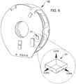
- FIG. 6 is a heart-side view of the control electronics 130 showing an accelerometer 210 included in the control electronics 130, in accordance with many embodiments.
- the accelerometer 210 is a three-axis accelerometer that measures accelerations experienced by the control electronics 130 (and thereby the VAD 14) in three orthogonal axes (i.e., an X-axis 212, a Y-axis 214, and a Z-axis 216).
- the X-axis 212 and the Y-axis 214 are each oriented orthogonal to an axis of rotation of the rotor 140
- the Z-axis 216 is parallel to the axis of rotation of the rotor 140.
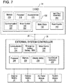
- FIG. 7 is a schematic diagram of a control system architecture of the mechanical support system 10.
- the driveline 26 couples the implanted VAD 14 to the external system controller 20, which monitors system operation via various software applications.
- the VAD 14 includes the control electronics 130, the Hall Effect Sensor assembly 200, the motor stator 120, the rotor/impeller 140.
- the control electronics include a processor 218, a memory device 220 (which can include read-only memory and/or random access-memory), the accelerometer 210, a motor control unit 222, and a communication unit 224.
- the memory device 220 stores one or more software applications that are executable by the processor 218 for various functions. For example, the one or more software applications can effectuate control the motor control unit 222 to effectuate radial levitation and rotational drive of the rotor 140 during operation.
- the one or more programs effectuate processing of output from the accelerometer 210 and/or operational parameters for the VAD 14 (e.g., drive current, rotational speed, flow rate, pressure differential across the impeller) as described herein to detect and/or measure patient physiological events and/or activity (e.g., patient orientation, patient activity level, heart wall motion, heart sounds, heart rate, respiratory rate, diaphragm contraction, cardiac cycle timing).
- the one or more programs can effectuate control of the motor control unit 222 to synchronize variation in output of the VAD 14 with the patient's cardiac cycle timing as described herein.
- the output of the VAD 14 can be increased over a period of time during ventricular systole so as to augment pumping of blood that occurs via contraction of the ventricle, thereby reducing the associated load on the ventricle.
- the one or more programs can effectuate control of the motor control unit 222 to vary output of the VAD 14 based on patient activity level. For example, in many embodiments, the output of the VAD 14 is increased in response to increased patient activity and decreased in response to decreased patient activity.
- the one or more programs can also be used to effectuate processing of the output from the accelerometer 210 and/or the operational parameters for the VAD 14 to generate patient monitoring data and/or VAD monitoring data as described herein.
- the communication unit 224 provides for wired and/or wireless communication between the VAD 14 and the external system controller 20.
- the motor control unit 222 is included in the VAD 14. In other embodiments, the motor control unit 222 is included in the external system controller 20.
- the external system controller 20 can in turn be coupled to the batteries 22 or an AC power module 30 that connects to an AC electrical outlet.
- the external system controller 20 can include a processor 226, a memory device 228 (which can include read-only memory and/or random access-memory), an emergency backup battery (EBB) to power the system (e.g., when the batteries 22 are depleted), one or more display units 230, one or more input/output devices 232, and a communication unit 234, which can have Bluetooth capabilities for wireless data communication.
- a processor 226, a memory device 228 which can include read-only memory and/or random access-memory
- EBB emergency backup battery
- An external computer having a system monitor 32 may further be coupled to the circulatory support system 10 for configuring the external system controller 20, the implanted VAD 14, and/or patient specific parameters; updating software on the external system controller 20 and/or the implanted VAD 14; monitoring system operation; and/or as a conduit for system inputs or outputs.
- the memory device 228 stores one or more software applications that are executable by the processor 226 for various functions.
- the one or more software applications can effectuate control the motor control unit 222 to effectuate radial levitation and rotational drive of the rotor 140 during operation.
- the one or more programs effectuate processing of output from the accelerometer 210 and/or operational parameters for the VAD 14 (e.g., drive current, rotational speed, flow rate, pressure differential across the impeller) as described herein to detect and/or measure patient physiological events and/or activity (e.g., patient orientation, patient activity level, heart wall motion, heart sounds, heart rate, respiratory rate, diaphragm contraction, cardiac cycle timing).
- the one or more programs can effectuate control of the motor control unit 222 to synchronize variation in output of the VAD 14 with the patient's cardiac cycle timing as described herein.
- the output of the VAD 14 can be increased over a period of time during ventricular systole so as to augment pumping of blood that occurs via contraction of the ventricle, thereby reducing the associated load on the ventricle.
- the one or more programs can effectuate control of the motor control unit 222 to vary output of the VAD 14 based on patient activity level. For example, in many embodiments, the output of the VAD 14 is increased in response to increased patient activity and decreased in response to decreased patient activity.
- the one or more programs can also be used to effectuate processing of the output from the accelerometer 210 and/or the operational parameters for the VAD 14 to generate patient monitoring data and/or VAD monitoring data as described herein.
- the communication unit 234 provides for wired and/or wireless communication between the external system controller 20 and the VAD 14 and/or the system monitor 32.
- FIG. 8 is a plot of raw accelerations of the VAD 14 measured by the three-axis accelerometer 210 during an animal study.
- the raw accelerations shown include X-axis acceleration 236, Y-axis acceleration 238, Z-axis acceleration 240, and a magnitude 242 of the raw acceleration.
- FIG. 8 also shows a flow rate 244 of the VAD 14 during the measurement of the raw accelerations.
- FIG. 9 is a plot of mean normalized accelerations of the VAD 14 generated from the raw accelerations of FIG. 8 .
- the mean normalized accelerations shown include X-axis mean normalized acceleration 246, Y-axis mean normalized acceleration 248, Z-axis mean normalized acceleration 250, and a magnitude 252 of the mean normalized acceleration.
- Each of the mean accelerations was produced by subtracting the corresponding average acceleration over the entire sample period from the corresponding raw acceleration plot (so that the resulting average is zero).
- FIG. 9 also shows the flow rate 244 of the VAD 14 during the measurement of the raw accelerations. To enhance legibility of FIG.
- a constant acceleration offset has been combined with each of the acceleration components (i.e., 300 mg added to the X-axis mean normalized acceleration 246, 100 mg has been added to the Y-axis mean normalized acceleration 248, 100 mg has been subtracted from the Z-axis mean normalized acceleration 250, and 300 mg has been subtracted from the magnitude 252 of the total mean normalized acceleration) so as to separate the plotted components.
- FIG. 10 is a plot of velocities of the VAD 14 generated via integration of the mean normalized accelerations of FIG. 9 .
- the output from at least three accelerometers can be integrated to determine the corresponding three-dimensional velocity.
- significant amounts of rotational motion may induce significant levels of error in the resulting three-dimensional velocity.
- one accelerometer can provide reasonable estimates of the velocity if the rotational motions are insignificant, rotational motions of a VAD may be significant. For example, if the beating of the heart rocks the accelerometer back and forth in a motion that includes rotation, an error due to centripetal acceleration may accumulate. The error may be quite small for a time, but may grow in size over time.
- acceleration due to gravity is filtered out prior to integrating the accelerations to determine the three-dimensional velocity.
- the velocities shown include X-axis velocity 254, Y-axis velocity 256, Z-axis velocity 258, and total velocity 260.
- FIG. 10 also shows the flow rate 244 of the VAD 14 during the measurement of the raw accelerations. To enhance legibility of FIG.
- a constant velocity offset has been combined with each of the velocity components (i.e., 30 mm/sec added to the X-axis velocity 254, 10 mm/sec has been added to the Y-axis velocity 256, 10 mm/sec has been subtracted from the Z-axis velocity 258, and 30 mm/sec has been subtracted from the total velocity 260) so as to separate the plotted components.
- FIG. 11 is a plot of displacements of the VAD 14 generated via integration of the velocities of FIG. 10 .
- the displacements shown include X-axis displacement 262, Y-axis displacement 264, Z-axis displacement 266, and total displacement 268.
- FIG. 11 also shows the flow rate 244 of the VAD 14 during the measurement of the raw accelerations. To enhance legibility of FIG.
- a constant displacement offset has been combined with each of the displacement components (i.e., 1 mm added to the X-axis displacement 262, 0.3 mm has been added to the Y-axis displacement 264, 0.3 mm has been subtracted from the Z-axis displacement 266, and 30 mm/sec has been subtracted from the total displacement 268) so as to separate the plotted components.
- the output from the accelerometer 210 includes acceleration due to gravity and is therefore indicative of the orientation of the VAD 14, and therefore also the patient 12, relative to vertical.
- Any suitable approach can be used to process the output from the accelerometer 210 to determine the orientation of the patient 12 and/or the VAD 12 relative to vertical.
- each of the X-axis acceleration 236, Y-axis acceleration 238, and Z-axis acceleration 240 can be processed to calculate a respective running average having a suitable time period (e.g., 10 to 15 seconds) corresponding to an X-axis gravity induced acceleration, a Y-axis gravity induced acceleration, and a Z-axis gravity induced acceleration, respectively.
- the X-axis gravity induced acceleration, Y-axis gravity induced acceleration, and the Z-axis gravity induced acceleration define a gravity vector that indicates the orientation of the accelerometer relative to vertical.
- Any suitable approach can be used to process the gravity vector to generate an indication of the orientation of the patient relative to a suitable reference axis or reference direction.
- the gravity vector can be transformed from the accelerometer axis system to a patient reference axis system, for example, with a patient X-axis extending forward relative to the patient's thorax, a patient Y-axis extending to the left relative to the patient's thorax, and a patient Z-axis extending toward the top of the patient's thorax.
- reference gravity orientation vectors corresponding to known orientations of the patient 12 and/or the VAD 14 can be generated by placing the patient 12 and/or the VAD 14 in known orientations relative to vertical (e.g., standing upright, laying horizontal on the patient's left side, laying horizontal on the patient's right side, laying horizontal on the patient's back, and laying horizontal on the patient's stomach).
- the gravity vector can be compared to each of one or more of the reference gravity orientation vectors using a known approach to determine a relative angle between the gravity vector and the respective reference gravity orientation vector.
- the resulting relative angle(s) are indicative of the orientation of the patient 12 and/or the VAD 14 relative to the reference orientations of the patient 12 and/or the VAD 14.
- the patient's respiration rate and the diaphragm contraction amplitude can be determined by processing the accelerometer output using a suitable band-pass filter (e.g., approximately 0.2 to 1.0 Hz (12 to 60 breaths per minute)) to isolate accelerations due to respiration.
- the resulting accelerations due to respiration can then be processed to determine corresponding respiration rate and diaphragm contraction amplitude.
- Frequency range and direction of movement can be used to isolate respiratory motion.
- accelerations due to respiration will typically have lower amplitudes (1 to 10 mg) and a regular pattern.
- the motion of the ventricular heart wall is monitored by processing the accelerometer output using a suitable band-pass filter (e.g., primary left ventrical wall motion range should be 0.5 to 3 Hz (30 to 180 BPM)) to isolate accelerations due to the ventricular heart wall motion.
- the heart wall motion can be processed to determine cardiac cycle timing, ventricle contractile strength, and ventricle contractile efficiency.
- Direction z-axis, in line with the inflow cannula
- frequency range, and timing regularity can be used to isolate LV wall motion. Transitions from periods of low accelerations to high accelerations (or changes in acceleration, jerk) can be used to indicate the start of a cardiac cycle (start of systole). Maximum acceleration can be used to estimate contractile strength.
- Contractile strength combined with min/mean/max flow through the pump can then be used to estimate contractile efficiency.
- the ventricle contractile strength and ventricle contractile efficiency can be monitored to monitor health of the patient's heart (e.g., detect signs of recovery or weakening).
- the heart wall motion can also be monitored to detect arrhythmia. Irregular cardiac cycle timing periods (start of systole) can be used to detect arrhythmia.
- heart rates above and below a normal range can be used to detect arrhythmia.
- the accelerometer output is processed to detect and/or measure heart sounds.
- the heart sounds that can be detected and/or measured include a first sound (Si) generated by closing of the atrioventricular valves during ventricular contraction and a second sound (S 2 ) generated by closing of the semilunar valves during ventricular diastole.
- the occurrence of aortic insufficiency (aka aortic regurgitation) generates a corresponding sound that can be detected via the accelerometer 210.
- the accelerometer output is processed using a suitable band-pass filter (e.g., 50 to 500 Hz) to isolate accelerations due to the heart sounds.
- the accelerations due to the heart sounds can then be processed to detect/measure the heart sounds.
- the heart sounds can be used to monitor the cardiac cycle timing of the heart, as well as to monitor the patient for the occurrence of aortic insufficiency.
- the accelerations measured by the accelerometer 210 include accelerations induced via operation of the VAD 14.
- the induced accelerations can include accelerations induced via vibrations of the rotor 140, speed of the rotor 140, change in speed of the rotor 140, and/or mass/balance of the rotor 140. Accelerations can also be induced as the result of ingestion of an object, by the VAD 14 such as a blood clot. Accelerations can also be induced by a suction event, which can occur when the VAD 14 over-extracts blood from the ventricle.
- the accelerometer output is processed using a suitable band-pass filter (e.g., 0.5 to 3.0 Hz) to isolate accelerations induced via operation of the VAD 14.
- the accelerations induced via operation of the VAD 14 can be processed to monitor for excessive rotor vibration, ingestion of an object, and/or the occurrence of a suction event.
- a suitable band-pass filter can be applied around the operating rotor speed (50-150 Hz) and potentially the subsequent harmonics. Changes in vibration amplitude (specifically increases) of the resulting filtered accelerations can be indicative of a rotor imbalance caused by either an ingested thrombus or thrombus forming on the rotor.
- Suction events can be detected via the combined occurrence of three events: (1) changes in LV wall motion (accelerometer), (2) low average flow through the pump (which can be detected via rotor drive current), and (3) low minimal flow fluctuations (which can be detected via the occurrence of small changes in drive current).
- the cardiac cycle timing of the patient is detected via monitoring of drive current supplied to the VAD 14, rotational speed of the rotor 140, flow rate of blood through the VAD 14, and/or pressure differential across the rotor 140. For example, during ventricular systole, variation in the ventricular pressure induces corresponding changes in the drive current supplied to the VAD 14 for a given rotational speed of the rotor 140. In some embodiments, the rotation speed of the rotor 140 is kept constant over one or more cardiac cycles to avoid inducing changes in the drive current due to changes in the rotational speed of the rotor 140. By monitoring the drive current supplied to the VAD 14, the cardiac cycle timing can be detected via detection of the time periods corresponding to ventricular systole.
- the rotor drive current essentially follows a sinusoidal shape throughout the cardiac cycle. Peak flows (and drive current) occur at maximum left ventricle pressure, which is in the middle of systole. Minimum flows (min drive current) occur at the lowest left ventricle pressure, which is the start of diastole.
- the start of diastole can be detected by detecting the minimum drive current. Peak systole can be detected by detecting maximum drive current. Start of systole can be detected by detecting a sudden change in drive current slope (dl/dt) at the end of diastole.
- the output of the accelerometer 210 is processed to measure an activity level of the patient 12, including deducing the patient's circadian rhythm.
- the output of the VAD 14 is varied based on the measured activity level so as to provide increased support in response to an increase in the measured activity level and decreased support in response to a decrease in the activity level.
- the average rotational speed of the rotor 140 is increased to increase the output of the VAD 14 and the average rotational speed is decreased to decrease the output of the VAD 14.
- the output of the accelerometer 210 can be processed to measure a number of different patient physiological processes that are indicative of the activity level of the patient 12.
- the accelerometer output can be processed using suitable approaches, such as those described herein, to measure respiration rate, diaphragm contraction amplitude, ventricle contraction amplitude, heart rate, vibration from walking/running, and/or orientation of the patient 12.
- the activity level of the patient 12 can be defined to be a suitable function of one or more of the respiration rate, the diaphragm contraction amplitude, the ventricle contraction amplitude, the heart rate, and/or the orientation of the patient 12.
- the output of the accelerometer 210 is processed to detect/measure the cardiac cycle timing for use in synchronization of operation of the VAD 14 with the cardiac cycle timing.
- the cardiac cycle timing can be determined based on any suitable indicator determined via processing of the accelerometer output, such as heart wall motion and heart sounds. Additionally, the cardiac cycle timing can be determined, as described herein, based on pump operating parameters, such as current, pump speed, and/or flow rate.
- FIG. 12 illustrates synchronization of speed variation of the VAD 14 with ventricular systole based on heart sounds, ventricular wall motion, and/or pump operating parameters, in accordance with many embodiments.
- both the atria and ventricles are relaxed (diastole). Blood flows into the atriums and into the ventricles from the atriums. Contraction of the atria (atrial systole) pumps additional blood from the atriums into the ventricles. Atrial systole ends prior to ventricular systole.
- each of the ventricular pressures 270 increases over the respective atrial pressure 272 (only one shown for clarity) thereby causing the respective atrial valve to close.
- the closing of the atrial valves generates the first heart sound (Si).
- Further contraction of the respective ventricle increases the ventricular pressure 270 to above the respective output blood vessel pressure (e.g., aortic pressure 274), thereby causing the respective semilunar valve to open and blood to flow out of the ventricle.
- Ventricular relaxation (ventricular diastole) follows ventricular systole.
- each of the ventricular pressures 270 drops below the respective output blood vessel pressure, thereby causing the respective semilunar valve to close.
- the closure of the semilunar valves generates the second heart sound (S 2 ).
- Further relaxation of the ventricles decreases each of the ventricular pressures below the respective atrial pressure (e.g., left atrial pressure 272), thereby causing the atrial valves to open.
- Heart wall motion 276 during contraction of the ventricles during ventricular systole induces accelerations of the VAD 14 that are measured by the accelerometer 210.
- the heart wall motion induced acceleration of the VAD 14 is primarily reflected in the Z-axis acceleration 240 measured by the accelerometer 210.
- the Z-axis displacement 266 can be processed to monitor the heart wall motion 276 to measure timing and strength of each ventricular systole, and thereby indicating cardiac cycle timing.
- Detection of the heart sounds (S 1 and S 2 ) can also be used to determine the cardiac cycle timing, either alone or in combination with the timing of ventricular systole determined via assessment of the heart wall motion 276.
- the VAD 14 is operated so as to vary output of the VAD 14 in synchronization with the cardiac cycle timing.
- the VAD 14 is operated to pump blood at a greater rate during ventricular systole than pumped by the VAD 14 during the rest of the cardiac cycle.
- the rotation speed of the rotor 140 is varied to vary the rate that blood is pumped by the VAD 14. Any suitable variation of the output of the VAD 14 can be used.
- the rotational speed of the rotor 140 can be varied during ventricular systole so as to increase the output of the VAD 14 during ventricular systole.
- the rotational speed of the rotor 140 varied during ventricular systole (i.e., increased from a first rotational speed (r1) to a second rotational speed (r2), maintained at the second rotational speed (r2) for a period of time, and then reduced back down to the first rotational speed (r1)).
- cardiac cycle timing observed during one or more previous cardiac cycles can be used to control timing of the variation in output of the VAD 14 during a current cardiac cycle.
- cardiac cycle timing for a target cardiac cycle can be used to control timing of the variation in output of the VAD 14 during the target cardiac cycle.
- FIG. 13 is a simplified schematic diagram of a method 300 in which accelerations of a VAD are measured and used to control operation of the VAD, monitor the patient in which the VAD is implanted, and/or monitor operation of the VAD.
- Any suitable circulation assist system that includes a VAD such as the circulation assist systems described herein, can be used to practice the method 300.
- Any suitable combination of the below described acts of the method 300 can be employed in any suitable order.
- any suitable set of the acts of the method 300 can be employed to control operation of the VAD based on patient activity level.
- Any suitable set of the acts of the method 300 can be employed to control operation of the VAD to vary output of the VAD in synch with a patient's cardiac cycle timing.
- Any suitable set of the acts of the method 300 can be employed to monitor the patient.
- any suitable set of the acts of the method 300 can be employed to monitor operation of the VAD.
- accelerations of the VAD are measured. Any suitable approach can be used to measure the acceleration of the VAD.
- the accelerations of the VAD 14 are measured via the accelerometer 210.
- the measured accelerations of the VAD are processed to monitor the orientation of the VAD and/or a patient in which the VAD is implanted.
- the measured accelerations can be processed as described herein to monitor the orientation of the VAD and/or the patient.
- the measured accelerations of the VAD are processed to track the patient's cardiac cycle timing.
- the measured accelerations can be processed as described herein to track the patient's cardiac cycle timing.
- operating parameters of the VAD are processed to track the patient's cardiac cycle timing.
- operating parameters of the VAD e.g., drive current
- the measured accelerations are processed to monitor the patient's activity level.
- the measured accelerations can be processed to monitor respiration rate, diaphragm contraction amplitude, heart rate, ventricle contraction amplitude, and/or the patient's orientation to monitor the patient's activity level as described herein.
- operation of the VAD is controlled in synch with the patient's cardiac cycle timing.
- operation of the VAD 14 can be controlled to increase output of the VAD 14 during ventricular systole as described herein.
- operation of the VAD is controlled based on the patient's activity level.
- the VAD 14 can be operated as described herein to increase output of the VAD 14 in response to an increase in patient activity level and to decrease output of the VAD 14 in response to a decrease in patient activity level.
- the measured accelerations are processed to generate VAD monitoring data.
- the measured accelerations of the VAD 14 can be processed as described herein to generate VAD monitoring data indicative of mass/balance of the rotor 140, detect ingestion of an object (e.g., a blood clot) by the VAD 14, and/or detect a suction event.
- an object e.g., a blood clot
- the measured accelerations are processed to generate patient monitoring data.
- the measured accelerations of the VAD 14 can be processed as described herein to generate patient monitoring data indicative of patient orientation, heart rate, respiration rate, ventricular contraction strength and/or efficiency, presence of absence of arrhythmia, patient activity level, and/or presence or absence of aortic insufficiency.
- the patient monitoring data is output for subsequent processing and/or display.
- the patient monitoring data can be stored in the VAD 14 and output to the system monitor 32 via the external system controller 20, or stored in the external system controller 20 and output directly to the system monitor 32.
- the VAD monitoring data is output for subsequent processing and/or display.
- the VAD monitoring data can be stored in the VAD 14 and output to the system monitor 32 via the external system controller 20, or stored in the external system controller 20 and output directly to the system monitor 32.
Landscapes
- Health & Medical Sciences (AREA)
- Heart & Thoracic Surgery (AREA)
- Engineering & Computer Science (AREA)
- Cardiology (AREA)
- Life Sciences & Earth Sciences (AREA)
- Anesthesiology (AREA)
- Biomedical Technology (AREA)
- Hematology (AREA)
- Mechanical Engineering (AREA)
- Animal Behavior & Ethology (AREA)
- General Health & Medical Sciences (AREA)
- Public Health (AREA)
- Veterinary Medicine (AREA)
- Vascular Medicine (AREA)
- Medical Informatics (AREA)
- External Artificial Organs (AREA)
Priority Applications (1)
| Application Number | Priority Date | Filing Date | Title |
|---|---|---|---|
| EP23150265.9A EP4190392A1 (fr) | 2018-07-17 | 2019-07-16 | Systèmes et procédés de détection inertielle pour diagnostics vad et commande en boucle fermée |
Applications Claiming Priority (1)
| Application Number | Priority Date | Filing Date | Title |
|---|---|---|---|
| US201862699500P | 2018-07-17 | 2018-07-17 |
Related Child Applications (1)
| Application Number | Title | Priority Date | Filing Date |
|---|---|---|---|
| EP23150265.9A Division EP4190392A1 (fr) | 2018-07-17 | 2019-07-16 | Systèmes et procédés de détection inertielle pour diagnostics vad et commande en boucle fermée |
Publications (2)
| Publication Number | Publication Date |
|---|---|
| EP3597231A1 true EP3597231A1 (fr) | 2020-01-22 |
| EP3597231B1 EP3597231B1 (fr) | 2023-01-11 |
Family
ID=67314631
Family Applications (2)
| Application Number | Title | Priority Date | Filing Date |
|---|---|---|---|
| EP19186464.4A Active EP3597231B1 (fr) | 2018-07-17 | 2019-07-16 | Systèmes et procédés de détection d'inertie pour diagnostics vad et commande en boucle fermée |
| EP23150265.9A Pending EP4190392A1 (fr) | 2018-07-17 | 2019-07-16 | Systèmes et procédés de détection inertielle pour diagnostics vad et commande en boucle fermée |
Family Applications After (1)
| Application Number | Title | Priority Date | Filing Date |
|---|---|---|---|
| EP23150265.9A Pending EP4190392A1 (fr) | 2018-07-17 | 2019-07-16 | Systèmes et procédés de détection inertielle pour diagnostics vad et commande en boucle fermée |
Country Status (2)
| Country | Link |
|---|---|
| US (3) | US11241570B2 (fr) |
| EP (2) | EP3597231B1 (fr) |
Cited By (42)
| Publication number | Priority date | Publication date | Assignee | Title |
|---|---|---|---|---|
| WO2021242659A1 (fr) * | 2020-05-26 | 2021-12-02 | Medtronic, Inc. | Régulation de flux fondée sur la position du corps et l'activité pour dispositif d'assistance ventriculaire (vad) avec dispositif de commande entièrement implantable |
| US11754075B2 (en) | 2018-07-10 | 2023-09-12 | Kardion Gmbh | Impeller for an implantable, vascular support system |
| US11804767B2 (en) | 2018-01-24 | 2023-10-31 | Kardion Gmbh | Magnetic coupling element with a magnetic bearing function |
| US11881721B2 (en) | 2018-05-02 | 2024-01-23 | Kardion Gmbh | Wireless energy transfer system with fault detection |
| US11944805B2 (en) | 2020-01-31 | 2024-04-02 | Kardion Gmbh | Pump for delivering a fluid and method of manufacturing a pump |
| US11996699B2 (en) | 2018-05-02 | 2024-05-28 | Kardion Gmbh | Receiving unit, transmission unit, power transmission system and method for wireless power transmission |
| US12005248B2 (en) | 2018-05-16 | 2024-06-11 | Kardion Gmbh | Rotor bearing system |
| US12064615B2 (en) | 2018-05-30 | 2024-08-20 | Kardion Gmbh | Axial-flow pump for a ventricular assist device and method for producing an axial-flow pump for a ventricular assist device |
| US12076549B2 (en) | 2018-07-20 | 2024-09-03 | Kardion Gmbh | Feed line for a pump unit of a cardiac assistance system, cardiac assistance system and method for producing a feed line for a pump unit of a cardiac assistance system |
| US12107474B2 (en) | 2018-05-16 | 2024-10-01 | Kardion Gmbh | End-face rotating joint for transmitting torques |
| US12102835B2 (en) | 2018-05-02 | 2024-10-01 | Kardion Gmbh | Transmission unit comprising a transmission coil and a temperature sensor |
| US12144976B2 (en) | 2018-06-21 | 2024-11-19 | Kardion Gmbh | Method and device for detecting a wear condition of a ventricular assist device and for operating same, and ventricular assist device |
| US12150647B2 (en) | 2016-06-06 | 2024-11-26 | Kardion Gmbh | Method for punching a lumen and implanting an implant device |
| US12178554B2 (en) | 2018-06-06 | 2024-12-31 | Kardion Gmbh | Systems and methods for determining a viscosity of a fluid |
| US12194287B2 (en) | 2018-05-30 | 2025-01-14 | Kardion Gmbh | Method of manufacturing electrical conductor tracks in a region of an intravascular blood pump |
| US12201823B2 (en) | 2018-05-30 | 2025-01-21 | Kardion Gmbh | Line device for conducting a blood flow for a heart support system, heart support system, and method for producing a line device |
| US12201821B2 (en) | 2018-06-06 | 2025-01-21 | Kardion Gmbh | Method for determining a flow rate of a fluid flowing through an implanted vascular support system, and implantable vascular support system |
| US12222267B2 (en) | 2018-06-06 | 2025-02-11 | Kardion Gmbh | Analysis device and method for analyzing a viscosity of a fluid |
| US12230868B2 (en) | 2018-05-02 | 2025-02-18 | Kardion Gmbh | Device for inductive energy transfer into a human body, for example, and use of said device |
| US12233250B2 (en) | 2018-05-02 | 2025-02-25 | Kardion Gmbh | Device for inductive energy transmission into a human body and use thereof |
| US12257424B2 (en) | 2018-06-06 | 2025-03-25 | Kardion Gmbh | Implantable ventricular assist system and method for operating same |
| US12263333B2 (en) | 2018-06-21 | 2025-04-01 | Kardion Gmbh | Stator vane device for guiding the flow of a fluid flowing out of an outlet opening of a ventricular assist device, ventricular assist device with stator vane device, method for operating a stator vane device and manufacturing method |
| US12311160B2 (en) | 2018-06-06 | 2025-05-27 | Kardion Gmbh | Method and system for determining the speed of sound in a fluid in the region of a cardiac support system |
| US12310708B2 (en) | 2018-06-06 | 2025-05-27 | Kardion Gmbh | Systems and methods for determining a flow speed of a fluid flowing through a cardiac assist device |
| US12324906B2 (en) | 2018-06-06 | 2025-06-10 | Kardion Gmbh | Systems and methods for determining a total blood volume flow in a cardiac support system and vascular support system |
| US12377256B2 (en) | 2018-06-06 | 2025-08-05 | Kardion Gmbh | Cardiac support system flow measurement using pressure sensors |
| US12383727B2 (en) | 2018-05-30 | 2025-08-12 | Kardion Gmbh | Motor housing module for a heart support system, and heart support system and method for mounting a heart support system |
| US12390633B2 (en) | 2018-08-07 | 2025-08-19 | Kardion Gmbh | Bearing device for a heart support system, and method for rinsing a space in a bearing device for a heart support system |
| US12400788B2 (en) | 2020-11-05 | 2025-08-26 | Kardion Gmbh | Device for inductive energy transmission in a human body and use of the device |
| US12403296B2 (en) | 2018-05-30 | 2025-09-02 | Kardion Gmbh | Apparatus for anchoring a ventricular assist system in a blood vessel, operating method, production method for producing an apparatus and ventricular assist system |
| EP4545133A3 (fr) * | 2019-10-25 | 2025-10-15 | Tc1 Llc | Systèmes d'assistance circulatoire comprenant un dispositif de commande et une pluralité de capteurs |
| US12447327B2 (en) | 2018-05-30 | 2025-10-21 | Kardion Gmbh | Electronics module and arrangement for a ventricular assist device, and method for producing a ventricular assist device |
| US12465744B2 (en) | 2018-07-10 | 2025-11-11 | Kardion Gmbh | Impeller housing for an implantable, vascular support system |
| US12476488B2 (en) | 2018-05-02 | 2025-11-18 | Kardion Gmbh | Energy transfer system and reception unit for the wireless transcutaneous transfer of energy |
| US12478267B2 (en) | 2018-06-06 | 2025-11-25 | Kardion Gmbh | Sensor head device for a minimal invasive ventricular assist device and method for producing such a sensor head device |
| US12478775B2 (en) | 2018-07-09 | 2025-11-25 | Kardion Gmbh | Cardiac assist system, and method for monitoring the integrity of a retaining structure of a cardiac assist system |
| US12491357B2 (en) | 2018-06-06 | 2025-12-09 | Kardion Gmbh | Systems and methods for determining a blood volume flow through a cardiac support system and vascular support system |
| US12508418B2 (en) | 2018-08-08 | 2025-12-30 | Kardion Gmbh | Device and method for monitoring the state of health of a patient |
| US12515036B2 (en) | 2020-09-14 | 2026-01-06 | Kardion Gmbh | Cardiovascular support pump having an impeller with a variable flow area |
| US12569671B2 (en) | 2018-06-06 | 2026-03-10 | Kardion Gmbh | Device and method for determination of a cardiac output for a cardiac assistance system |
| US12589238B2 (en) | 2018-05-16 | 2026-03-31 | Kardion Gmbh | Rotor, magnetic coupling device, electric motor for a cardiac support system, pump unit for a cardiac support system, and method for producing a rotor |
| US12589237B2 (en) | 2020-11-20 | 2026-03-31 | Kardion Gmbh | Mechanical circulatory support system with guidewire aid |
Families Citing this family (4)
| Publication number | Priority date | Publication date | Assignee | Title |
|---|---|---|---|---|
| CA3149412A1 (fr) * | 2019-08-31 | 2021-03-04 | Benjamin D. Pless | Dispositif de sauvetage d'une surdose d'opioide |
| JP7656624B2 (ja) * | 2020-03-18 | 2025-04-03 | スカンジナビアン・リアル・ハート・アクチエボラーグ | 圧力センサ配置および方法 |
| US12502524B2 (en) | 2021-12-03 | 2025-12-23 | Kardion Gmbh | Cardiac pump with optical fiber for laser doppler |
| CN117982793B (zh) * | 2024-04-07 | 2024-11-15 | 深圳核心医疗科技股份有限公司 | 叶轮位置控制方法及装置 |
Citations (47)
| Publication number | Priority date | Publication date | Assignee | Title |
|---|---|---|---|---|
| US5695471A (en) | 1996-02-20 | 1997-12-09 | Kriton Medical, Inc. | Sealless rotary blood pump with passive magnetic radial bearings and blood immersed axial bearings |
| US5708346A (en) | 1994-01-10 | 1998-01-13 | Sulzer Electronics Ag | Method and control apparatus for controlling an AC-machine |
| US5888242A (en) | 1996-11-01 | 1999-03-30 | Nimbus, Inc. | Speed control system for implanted blood pumps |
| US6053705A (en) | 1996-09-10 | 2000-04-25 | Sulzer Electronics Ag | Rotary pump and process to operate it |
| US6071093A (en) | 1996-10-18 | 2000-06-06 | Abiomed, Inc. | Bearingless blood pump and electronic drive system |
| US6100618A (en) | 1995-04-03 | 2000-08-08 | Sulzer Electronics Ag | Rotary machine with an electromagnetic rotary drive |
| US6116862A (en) | 1996-06-25 | 2000-09-12 | Medos Medizintechnik Gmbh | Blood pump |
| US6186665B1 (en) | 1999-01-26 | 2001-02-13 | Nimbus, Inc. | Motor rotor bearing assembly for a blood pump |
| US6222290B1 (en) | 1998-08-24 | 2001-04-24 | Sulzer Electronics Ag | Sensor arrangement in an electromagnetic rotary drive and a method for the operation of a rotary drive of this kind |
| US6234772B1 (en) | 1999-04-28 | 2001-05-22 | Kriton Medical, Inc. | Rotary blood pump |
| US6249067B1 (en) | 1998-08-24 | 2001-06-19 | Sulzer Electronics Ag | Method and sensor arrangement for the determination of the radial position of a permanent magnetic rotor |
| US6264635B1 (en) | 1998-12-03 | 2001-07-24 | Kriton Medical, Inc. | Active magnetic bearing system for blood pump |
| US6278251B1 (en) | 1998-09-24 | 2001-08-21 | Sulzer Electronics Ag | Permanent magnetically excited electrical rotary drive |
| US6351048B1 (en) | 1999-06-22 | 2002-02-26 | Levitronix Llc | Electrical rotary drive |
| US6634224B1 (en) | 1998-07-10 | 2003-10-21 | Levitronix Llc | Method for the determination of the pressure in and/or of the through-flow through a pump |
| US6688861B2 (en) | 1996-02-20 | 2004-02-10 | Heartware, Inc. | Sealless rotary blood pump |
| WO2004028593A1 (fr) * | 2002-09-30 | 2004-04-08 | Ventrassist Pty Ltd | Systeme de controle receptif a une demande biologique |
| US20050071001A1 (en) | 2003-09-30 | 2005-03-31 | Robert Jarvik | Artificial heart power and control system |
| US6879074B2 (en) | 2000-07-16 | 2005-04-12 | Levitronix Llc | Stator field providing torque and levitation |
| US6991595B2 (en) | 2002-04-19 | 2006-01-31 | Thoratec Corporation | Adaptive speed control for blood pump |
| US7112903B1 (en) | 1997-08-25 | 2006-09-26 | Levitronix Llc | Magnetically journalled rotational arrangement including a rotor for generating a unipolar bias magnetic flux |
| EP1812094A2 (fr) | 2004-11-16 | 2007-08-01 | Micromed Cardiovascular, Inc. | Appareil de controle des donnees a distance pour systeme de pompe cardiaque |
| US7699586B2 (en) | 2004-12-03 | 2010-04-20 | Heartware, Inc. | Wide blade, axial flow pump |
| US7976271B2 (en) | 2006-01-13 | 2011-07-12 | Heartware, Inc. | Stabilizing drive for contactless rotary blood pump impeller |
| US8007254B2 (en) | 2004-12-03 | 2011-08-30 | Heartware, Inc. | Axial flow pump with multi-grooved rotor |
| US8152493B2 (en) | 2007-04-30 | 2012-04-10 | Hearthware Inc. | Centrifugal rotary blood pump with impeller having a hydrodynamic thrust bearing surface |
| US8323174B2 (en) | 2010-10-22 | 2012-12-04 | Nupulse, Inc. | Skin interface for ventricular assist device |
| US8449444B2 (en) | 2009-02-27 | 2013-05-28 | Thoratec Corporation | Blood flow meter |
| US8506471B2 (en) | 2010-09-24 | 2013-08-13 | Thoratec Corporation | Generating artificial pulse |
| WO2013119752A2 (fr) * | 2012-02-07 | 2013-08-15 | Hridaya, Inc. | Dispositif d'aide au flux hémodynamique |
| US8562508B2 (en) | 2009-12-30 | 2013-10-22 | Thoratec Corporation | Mobility-enhancing blood pump system |
| US20130314047A1 (en) | 2012-05-24 | 2013-11-28 | Heartware, Inc. | Low-power battery pack with safety system |
| US8597350B2 (en) | 2010-12-09 | 2013-12-03 | Heartware, Inc. | Controller and power source for implantable blood pump |
| US8652024B1 (en) | 2013-01-23 | 2014-02-18 | Thoratec Corporation | Sterilizable cable system for implantable blood pump |
| US8657733B2 (en) | 2005-11-04 | 2014-02-25 | Thoratec Corporation | Control systems for rotary blood pumps |
| US8852072B2 (en) | 2008-02-08 | 2014-10-07 | Heartware, Inc. | Ventricular assist device for intraventricular placement |
| US8864643B2 (en) | 2011-10-13 | 2014-10-21 | Thoratec Corporation | Pump and method for mixed flow blood pumping |
| US8882744B2 (en) | 2012-02-27 | 2014-11-11 | Thoratec Corporation | Quick-connect outflow tube for ventricular assist device |
| WO2014207225A1 (fr) * | 2013-06-27 | 2014-12-31 | Oslo Universitetssykehus Hf | Surveillance d'un dispositif d'assistance cardiaque |
| WO2015059158A1 (fr) * | 2013-10-22 | 2015-04-30 | Berlin Heart Gmbh | Procédé pour faire fonctionner un dispositif de pompage et dispositif de pompage |
| US9068572B2 (en) | 2010-07-12 | 2015-06-30 | Thoratec Corporation | Centrifugal pump apparatus |
| US9079043B2 (en) | 2011-11-21 | 2015-07-14 | Thoratec Corporation | Transcutaneous power transmission utilizing non-planar resonators |
| US9091271B2 (en) | 2010-08-20 | 2015-07-28 | Thoratec Corporation | Implantable blood pump |
| US9265870B2 (en) | 2010-10-13 | 2016-02-23 | Thoratec Corporation | Pumping blood |
| US9382908B2 (en) | 2010-09-14 | 2016-07-05 | Thoratec Corporation | Centrifugal pump apparatus |
| WO2018020161A1 (fr) * | 2016-07-26 | 2018-02-01 | Fineheart | Procédé de gestion d'une pompe cardiaque |
| US9901666B2 (en) | 2015-07-20 | 2018-02-27 | Tc1 Llc | Flow estimation using hall-effect sensors for measuring impeller eccentricity |
Family Cites Families (74)
| Publication number | Priority date | Publication date | Assignee | Title |
|---|---|---|---|---|
| US3911897A (en) | 1974-04-05 | 1975-10-14 | Jr Frank A Leachman | Heart assist device |
| US5139517A (en) | 1989-11-08 | 1992-08-18 | Corral David F | Orthotopic intraventricular heart pump |
| US5318592A (en) | 1991-09-12 | 1994-06-07 | BIOTRONIK, Mess- und Therapiegerate GmbH & Co., Ingenieurburo Berlin | Cardiac therapy system |
| US5503615A (en) | 1994-08-26 | 1996-04-02 | Goldstein; Bernard | Implantable cardiac ventricular assist device and controller thereof |
| US6111520A (en) | 1997-04-18 | 2000-08-29 | Georgia Tech Research Corp. | System and method for the wireless sensing of physical properties |
| US6889082B2 (en) | 1997-10-09 | 2005-05-03 | Orqis Medical Corporation | Implantable heart assist system and method of applying same |
| US6278379B1 (en) | 1998-04-02 | 2001-08-21 | Georgia Tech Research Corporation | System, method, and sensors for sensing physical properties |
| US8244370B2 (en) | 2001-04-13 | 2012-08-14 | Greatbatch Ltd. | Band stop filter employing a capacitor and an inductor tank circuit to enhance MRI compatibility of active medical devices |
| US6585635B1 (en) | 1999-09-17 | 2003-07-01 | Core Medical, Inc. | Method and system for pericardial modification |
| GB0023412D0 (en) | 2000-09-23 | 2000-11-08 | Khaghani Asghar | Aortic counterpulsator |
| SE523852C2 (sv) | 2001-04-10 | 2004-05-25 | Azad Al-Najjar | Hjärtprotes |
| US7853325B2 (en) | 2001-04-13 | 2010-12-14 | Greatbatch Ltd. | Cylindrical bandstop filters for medical lead systems |
| US8712544B2 (en) | 2001-04-13 | 2014-04-29 | Greatbatch Ltd. | Electromagnetic shield for a passive electronic component in an active medical device implantable lead |
| US8145324B1 (en) | 2001-04-13 | 2012-03-27 | Greatbatch Ltd. | Implantable lead bandstop filter employing an inductive coil with parasitic capacitance to enhance MRI compatibility of active medical devices |
| US6643420B2 (en) | 2001-12-28 | 2003-11-04 | Digital Optics Corp. | Optical subassembly |
| US7396327B2 (en) | 2002-01-07 | 2008-07-08 | Micromed Technology, Inc. | Blood pump system and method of operation |
| US6855115B2 (en) | 2002-01-22 | 2005-02-15 | Cardiomems, Inc. | Implantable wireless sensor for pressure measurement within the heart |
| US7029433B2 (en) | 2002-03-16 | 2006-04-18 | Chang Sheldon S | Device for cardiac restoration |
| US6772011B2 (en) | 2002-08-20 | 2004-08-03 | Thoratec Corporation | Transmission of information from an implanted medical device |
| US7245117B1 (en) | 2004-11-01 | 2007-07-17 | Cardiomems, Inc. | Communicating with implanted wireless sensor |
| ES2561354T3 (es) | 2003-10-31 | 2016-02-25 | Sunshine Heart Company Pty Ltd | Sistema de control de sincronización |
| US7520850B2 (en) | 2003-11-19 | 2009-04-21 | Transoma Medical, Inc. | Feedback control and ventricular assist devices |
| LT1715902T (lt) | 2004-01-08 | 2016-11-10 | Sullivan, Paul Joseph | Neišardomas fluido perdavimo įrenginys |
| US7513864B2 (en) * | 2004-07-09 | 2009-04-07 | Kantrowitz Allen B | Synchronization system between aortic valve and cardiac assist device |
| US7828711B2 (en) * | 2004-08-16 | 2010-11-09 | Cardiac Pacemakers, Inc. | Method and apparatus for modulating cellular growth and regeneration using ventricular assist device |
| US20060064133A1 (en) | 2004-09-17 | 2006-03-23 | Cardiac Pacemakers, Inc. | System and method for deriving relative physiologic measurements using an external computing device |
| AU2006220733B2 (en) | 2005-03-04 | 2011-01-27 | Cardiomems, Inc. | Communicating with an implanted wireless sensor |
| US8010209B2 (en) | 2005-10-14 | 2011-08-30 | Nanostim, Inc. | Delivery system for implantable biostimulator |
| US8224462B2 (en) | 2005-11-11 | 2012-07-17 | Greatbatch Ltd. | Medical lead system utilizing electromagnetic bandstop filters |
| WO2007089500A2 (fr) | 2006-01-30 | 2007-08-09 | Pong-Jeu Lu | Dispositif d'assistance bi-ventriculaire a double pulsation |
| AU2007201127B2 (en) | 2006-03-23 | 2012-02-09 | Thoratec Corporation | System For Preventing Diastolic Heart Failure |
| US20100268333A1 (en) | 2009-04-16 | 2010-10-21 | Gohean Jeffrey R | System and method for controlling pump |
| DE102006035548B4 (de) | 2006-07-27 | 2009-02-12 | Deutsches Zentrum für Luft- und Raumfahrt e.V. | Kunstherz |
| US7963905B2 (en) | 2006-10-11 | 2011-06-21 | Thoratec Corporation | Control system for a blood pump |
| AU2008261920A1 (en) | 2007-06-06 | 2008-12-18 | Worldheart Corporation | Wearable VAD controller with reserve battery |
| US20100121133A1 (en) | 2008-11-07 | 2010-05-13 | Schumer Douglas B | Apparatus and methods for measuring pressure and flow in cardiac assist devices and peripheral vasculature |
| US8562507B2 (en) | 2009-02-27 | 2013-10-22 | Thoratec Corporation | Prevention of aortic valve fusion |
| EP2525870B1 (fr) | 2010-01-19 | 2019-03-13 | Heartware, Inc. | Vad à réactivité physiologique |
| DE102010011798B4 (de) | 2010-03-17 | 2017-07-13 | Fresenius Medical Care Deutschland Gmbh | Verfahren und Vorrichtung zur Druck- oder Volumenstrombestimmung von medizinischen Fluiden |
| US20110270331A1 (en) | 2010-04-02 | 2011-11-03 | Sunshine Heart Company Pty Ltd | Combination heart assist systems, methods, and devices |
| US8901775B2 (en) | 2010-12-10 | 2014-12-02 | Everheart Systems, Inc. | Implantable wireless power system |
| EP2627403A4 (fr) | 2010-10-12 | 2014-03-26 | Nanostim Inc | Capteur de température pour stimulateur cardiaque sans fil |
| US8608636B2 (en) | 2010-11-12 | 2013-12-17 | Libraheart, Inc.V | Ventricular assist device cannula and ventricular assist device including the same |
| CA2820886A1 (fr) | 2010-12-08 | 2012-06-14 | Thoratec Corporation | Ligne conductrice modulaire |
| WO2012112378A2 (fr) | 2011-02-18 | 2012-08-23 | Vascor Inc. | Systèmes d'assistance circulatoire |
| EP2570143B1 (fr) | 2011-09-14 | 2014-01-15 | BIOTRONIK SE & Co. KG | Appareil thérapeutique cardiaque implantable |
| WO2013112550A1 (fr) | 2012-01-24 | 2013-08-01 | Thoratec Corporation | Ensemble câble de transmission |
| EP3159023B1 (fr) | 2012-03-05 | 2017-11-29 | Tc1 Llc | Methode de calibrage de pompes medicales implantables |
| WO2013184932A1 (fr) | 2012-06-06 | 2013-12-12 | Heartware, Inc. | Algorithme de modification de vitesse pour une pompe à sang à écoulement continu |
| US20150174307A1 (en) | 2012-07-19 | 2015-06-25 | Regents Of The University Of Minnesota | Cardiac assist device with pulse wave analysis |
| JP6268178B2 (ja) | 2012-09-05 | 2018-01-24 | ハートウェア, インコーポレイテッドHeartware, Inc. | Vadに一体化された流量センサ |
| US10022480B2 (en) | 2012-09-21 | 2018-07-17 | Reinheart Gmbh | Ventricular assist device and method of controlling same |
| US9090271B2 (en) | 2012-10-24 | 2015-07-28 | Progress Rail Services Corporation | System and method for characterizing dragging equipment |
| US20140188148A1 (en) | 2012-12-27 | 2014-07-03 | Pieter W.C.J. le Blanc | Surgical tunneler |
| EP2796156A1 (fr) | 2013-04-24 | 2014-10-29 | ETH Zurich | Appareil biomédical destiné à pomper le sang d'un patient humain ou animal par un circuit sanguin intra ou extracorporel secondaire |
| US10052420B2 (en) | 2013-04-30 | 2018-08-21 | Tc1 Llc | Heart beat identification and pump speed synchronization |
| US9592327B2 (en) * | 2013-09-06 | 2017-03-14 | Cardiac Pacemakers, Inc. | Systems and methods for heart failure management |
| CN104511060A (zh) | 2013-10-03 | 2015-04-15 | 北京精密机电控制设备研究所 | 血泵控制系统及血泵系统 |
| CN110101927B (zh) | 2014-04-15 | 2021-10-08 | Tc1有限责任公司 | 用于控制血泵的方法和系统 |
| EP2962710A1 (fr) | 2014-07-03 | 2016-01-06 | Berlin Heart GmbH | Procédé et système d'assistance ventriculaire destinés à déterminer une pression d'évacuation |
| US20160058930A1 (en) | 2014-08-26 | 2016-03-03 | Thoratec Corporation | Blood pump and method of suction detection |
| US9623161B2 (en) | 2014-08-26 | 2017-04-18 | Tc1 Llc | Blood pump and method of suction detection |
| JP2018507085A (ja) | 2015-02-24 | 2018-03-15 | ハートウェア、インコーポレイテッド | 徐脈治療用血液ポンプ |
| WO2017015210A1 (fr) | 2015-07-20 | 2017-01-26 | Thoratec Corporation | Tensiomètre pour l'estimation de débit |
| CN108430532B (zh) | 2015-12-28 | 2020-12-11 | 心脏器械股份有限公司 | 具有自适应启动的泵电机控制 |
| CN108430531B (zh) | 2015-12-28 | 2020-09-22 | 心脏器械股份有限公司 | Vad控制器测试仪 |
| US10398820B2 (en) | 2016-02-12 | 2019-09-03 | Mallinckrodt Hospital Products IP Limited | Use and monitoring of inhaled nitric oxide with left ventricular assist devices |
| EP3213781A1 (fr) | 2016-03-02 | 2017-09-06 | ETH Zurich | Appareil biomédical avec une pompe sanguine régulée en pression |
| WO2018017361A1 (fr) * | 2016-07-20 | 2018-01-25 | Cardiac Pacemakers, Inc. | Procédé et système de détermination d'un temps de stimulation dans un système de pacemaker cardiaque sans fil |
| US20180050348A1 (en) | 2016-08-19 | 2018-02-22 | Mark Whitney | Quench water hydrocyclone |
| WO2018038713A1 (fr) * | 2016-08-24 | 2018-03-01 | Avent, Inc. | Indicateur de débit pour pompe de perfusion. |
| WO2018183567A1 (fr) | 2017-03-29 | 2018-10-04 | Tc1 Llc | Architecture et procédés de communication pour systèmes de traitement cardiaque |
| WO2018183568A1 (fr) | 2017-03-29 | 2018-10-04 | Tc1 Llc | Dispositifs d'assistance ventriculaire à détection de pression et procédés d'utilisation |
| WO2018183565A1 (fr) | 2017-03-29 | 2018-10-04 | Harjes Daniel I | Ajustement de protocole sur la base d'un rythme cardiaque irrégulier |
-
2019
- 2019-07-15 US US16/511,641 patent/US11241570B2/en active Active
- 2019-07-16 EP EP19186464.4A patent/EP3597231B1/fr active Active
- 2019-07-16 EP EP23150265.9A patent/EP4190392A1/fr active Pending
-
2022
- 2022-01-13 US US17/574,905 patent/US12064612B2/en active Active
-
2024
- 2024-07-11 US US18/770,398 patent/US20240358995A1/en active Pending
Patent Citations (51)
| Publication number | Priority date | Publication date | Assignee | Title |
|---|---|---|---|---|
| US5708346A (en) | 1994-01-10 | 1998-01-13 | Sulzer Electronics Ag | Method and control apparatus for controlling an AC-machine |
| US6100618A (en) | 1995-04-03 | 2000-08-08 | Sulzer Electronics Ag | Rotary machine with an electromagnetic rotary drive |
| US5695471A (en) | 1996-02-20 | 1997-12-09 | Kriton Medical, Inc. | Sealless rotary blood pump with passive magnetic radial bearings and blood immersed axial bearings |
| US6688861B2 (en) | 1996-02-20 | 2004-02-10 | Heartware, Inc. | Sealless rotary blood pump |
| US6116862A (en) | 1996-06-25 | 2000-09-12 | Medos Medizintechnik Gmbh | Blood pump |
| US6053705A (en) | 1996-09-10 | 2000-04-25 | Sulzer Electronics Ag | Rotary pump and process to operate it |
| US6071093A (en) | 1996-10-18 | 2000-06-06 | Abiomed, Inc. | Bearingless blood pump and electronic drive system |
| US5888242A (en) | 1996-11-01 | 1999-03-30 | Nimbus, Inc. | Speed control system for implanted blood pumps |
| US7112903B1 (en) | 1997-08-25 | 2006-09-26 | Levitronix Llc | Magnetically journalled rotational arrangement including a rotor for generating a unipolar bias magnetic flux |
| US6634224B1 (en) | 1998-07-10 | 2003-10-21 | Levitronix Llc | Method for the determination of the pressure in and/or of the through-flow through a pump |
| US6355998B1 (en) | 1998-08-24 | 2002-03-12 | Levitronix Llc | Sensor arrangement in an electromagnetic rotary drive and a method for the operation of a rotary drive of this kind |
| US6249067B1 (en) | 1998-08-24 | 2001-06-19 | Sulzer Electronics Ag | Method and sensor arrangement for the determination of the radial position of a permanent magnetic rotor |
| US6222290B1 (en) | 1998-08-24 | 2001-04-24 | Sulzer Electronics Ag | Sensor arrangement in an electromagnetic rotary drive and a method for the operation of a rotary drive of this kind |
| US6278251B1 (en) | 1998-09-24 | 2001-08-21 | Sulzer Electronics Ag | Permanent magnetically excited electrical rotary drive |
| US6264635B1 (en) | 1998-12-03 | 2001-07-24 | Kriton Medical, Inc. | Active magnetic bearing system for blood pump |
| US6186665B1 (en) | 1999-01-26 | 2001-02-13 | Nimbus, Inc. | Motor rotor bearing assembly for a blood pump |
| US6234772B1 (en) | 1999-04-28 | 2001-05-22 | Kriton Medical, Inc. | Rotary blood pump |
| US6351048B1 (en) | 1999-06-22 | 2002-02-26 | Levitronix Llc | Electrical rotary drive |
| US6879074B2 (en) | 2000-07-16 | 2005-04-12 | Levitronix Llc | Stator field providing torque and levitation |
| US6991595B2 (en) | 2002-04-19 | 2006-01-31 | Thoratec Corporation | Adaptive speed control for blood pump |
| WO2004028593A1 (fr) * | 2002-09-30 | 2004-04-08 | Ventrassist Pty Ltd | Systeme de controle receptif a une demande biologique |
| US20050071001A1 (en) | 2003-09-30 | 2005-03-31 | Robert Jarvik | Artificial heart power and control system |
| EP1812094A2 (fr) | 2004-11-16 | 2007-08-01 | Micromed Cardiovascular, Inc. | Appareil de controle des donnees a distance pour systeme de pompe cardiaque |
| US7699586B2 (en) | 2004-12-03 | 2010-04-20 | Heartware, Inc. | Wide blade, axial flow pump |
| US8668473B2 (en) | 2004-12-03 | 2014-03-11 | Heartware, Inc. | Axial flow pump with multi-grooved rotor |
| US8007254B2 (en) | 2004-12-03 | 2011-08-30 | Heartware, Inc. | Axial flow pump with multi-grooved rotor |
| US8419609B2 (en) | 2005-10-05 | 2013-04-16 | Heartware Inc. | Impeller for a rotary ventricular assist device |
| US8657733B2 (en) | 2005-11-04 | 2014-02-25 | Thoratec Corporation | Control systems for rotary blood pumps |
| US7976271B2 (en) | 2006-01-13 | 2011-07-12 | Heartware, Inc. | Stabilizing drive for contactless rotary blood pump impeller |
| US7997854B2 (en) | 2006-01-13 | 2011-08-16 | Heartware, Inc. | Shrouded thrust bearings |
| US8152493B2 (en) | 2007-04-30 | 2012-04-10 | Hearthware Inc. | Centrifugal rotary blood pump with impeller having a hydrodynamic thrust bearing surface |
| US8852072B2 (en) | 2008-02-08 | 2014-10-07 | Heartware, Inc. | Ventricular assist device for intraventricular placement |
| US8449444B2 (en) | 2009-02-27 | 2013-05-28 | Thoratec Corporation | Blood flow meter |
| US8562508B2 (en) | 2009-12-30 | 2013-10-22 | Thoratec Corporation | Mobility-enhancing blood pump system |
| US9068572B2 (en) | 2010-07-12 | 2015-06-30 | Thoratec Corporation | Centrifugal pump apparatus |
| US9091271B2 (en) | 2010-08-20 | 2015-07-28 | Thoratec Corporation | Implantable blood pump |
| US9382908B2 (en) | 2010-09-14 | 2016-07-05 | Thoratec Corporation | Centrifugal pump apparatus |
| US8506471B2 (en) | 2010-09-24 | 2013-08-13 | Thoratec Corporation | Generating artificial pulse |
| US9265870B2 (en) | 2010-10-13 | 2016-02-23 | Thoratec Corporation | Pumping blood |
| US8323174B2 (en) | 2010-10-22 | 2012-12-04 | Nupulse, Inc. | Skin interface for ventricular assist device |
| US8597350B2 (en) | 2010-12-09 | 2013-12-03 | Heartware, Inc. | Controller and power source for implantable blood pump |
| US8864643B2 (en) | 2011-10-13 | 2014-10-21 | Thoratec Corporation | Pump and method for mixed flow blood pumping |
| US9079043B2 (en) | 2011-11-21 | 2015-07-14 | Thoratec Corporation | Transcutaneous power transmission utilizing non-planar resonators |
| WO2013119752A2 (fr) * | 2012-02-07 | 2013-08-15 | Hridaya, Inc. | Dispositif d'aide au flux hémodynamique |
| US8882744B2 (en) | 2012-02-27 | 2014-11-11 | Thoratec Corporation | Quick-connect outflow tube for ventricular assist device |
| US20130314047A1 (en) | 2012-05-24 | 2013-11-28 | Heartware, Inc. | Low-power battery pack with safety system |
| US8652024B1 (en) | 2013-01-23 | 2014-02-18 | Thoratec Corporation | Sterilizable cable system for implantable blood pump |
| WO2014207225A1 (fr) * | 2013-06-27 | 2014-12-31 | Oslo Universitetssykehus Hf | Surveillance d'un dispositif d'assistance cardiaque |
| WO2015059158A1 (fr) * | 2013-10-22 | 2015-04-30 | Berlin Heart Gmbh | Procédé pour faire fonctionner un dispositif de pompage et dispositif de pompage |
| US9901666B2 (en) | 2015-07-20 | 2018-02-27 | Tc1 Llc | Flow estimation using hall-effect sensors for measuring impeller eccentricity |
| WO2018020161A1 (fr) * | 2016-07-26 | 2018-02-01 | Fineheart | Procédé de gestion d'une pompe cardiaque |
Cited By (44)
| Publication number | Priority date | Publication date | Assignee | Title |
|---|---|---|---|---|
| US12150647B2 (en) | 2016-06-06 | 2024-11-26 | Kardion Gmbh | Method for punching a lumen and implanting an implant device |
| US11804767B2 (en) | 2018-01-24 | 2023-10-31 | Kardion Gmbh | Magnetic coupling element with a magnetic bearing function |
| US12102835B2 (en) | 2018-05-02 | 2024-10-01 | Kardion Gmbh | Transmission unit comprising a transmission coil and a temperature sensor |
| US11881721B2 (en) | 2018-05-02 | 2024-01-23 | Kardion Gmbh | Wireless energy transfer system with fault detection |
| US12230868B2 (en) | 2018-05-02 | 2025-02-18 | Kardion Gmbh | Device for inductive energy transfer into a human body, for example, and use of said device |
| US11996699B2 (en) | 2018-05-02 | 2024-05-28 | Kardion Gmbh | Receiving unit, transmission unit, power transmission system and method for wireless power transmission |
| US12476488B2 (en) | 2018-05-02 | 2025-11-18 | Kardion Gmbh | Energy transfer system and reception unit for the wireless transcutaneous transfer of energy |
| US12233250B2 (en) | 2018-05-02 | 2025-02-25 | Kardion Gmbh | Device for inductive energy transmission into a human body and use thereof |
| US12589238B2 (en) | 2018-05-16 | 2026-03-31 | Kardion Gmbh | Rotor, magnetic coupling device, electric motor for a cardiac support system, pump unit for a cardiac support system, and method for producing a rotor |
| US12005248B2 (en) | 2018-05-16 | 2024-06-11 | Kardion Gmbh | Rotor bearing system |
| US12107474B2 (en) | 2018-05-16 | 2024-10-01 | Kardion Gmbh | End-face rotating joint for transmitting torques |
| US12383727B2 (en) | 2018-05-30 | 2025-08-12 | Kardion Gmbh | Motor housing module for a heart support system, and heart support system and method for mounting a heart support system |
| US12064615B2 (en) | 2018-05-30 | 2024-08-20 | Kardion Gmbh | Axial-flow pump for a ventricular assist device and method for producing an axial-flow pump for a ventricular assist device |
| US12447327B2 (en) | 2018-05-30 | 2025-10-21 | Kardion Gmbh | Electronics module and arrangement for a ventricular assist device, and method for producing a ventricular assist device |
| US12403296B2 (en) | 2018-05-30 | 2025-09-02 | Kardion Gmbh | Apparatus for anchoring a ventricular assist system in a blood vessel, operating method, production method for producing an apparatus and ventricular assist system |
| US12194287B2 (en) | 2018-05-30 | 2025-01-14 | Kardion Gmbh | Method of manufacturing electrical conductor tracks in a region of an intravascular blood pump |
| US12201823B2 (en) | 2018-05-30 | 2025-01-21 | Kardion Gmbh | Line device for conducting a blood flow for a heart support system, heart support system, and method for producing a line device |
| US12178554B2 (en) | 2018-06-06 | 2024-12-31 | Kardion Gmbh | Systems and methods for determining a viscosity of a fluid |
| US12222267B2 (en) | 2018-06-06 | 2025-02-11 | Kardion Gmbh | Analysis device and method for analyzing a viscosity of a fluid |
| US12201821B2 (en) | 2018-06-06 | 2025-01-21 | Kardion Gmbh | Method for determining a flow rate of a fluid flowing through an implanted vascular support system, and implantable vascular support system |
| US12478267B2 (en) | 2018-06-06 | 2025-11-25 | Kardion Gmbh | Sensor head device for a minimal invasive ventricular assist device and method for producing such a sensor head device |
| US12257424B2 (en) | 2018-06-06 | 2025-03-25 | Kardion Gmbh | Implantable ventricular assist system and method for operating same |
| US12491357B2 (en) | 2018-06-06 | 2025-12-09 | Kardion Gmbh | Systems and methods for determining a blood volume flow through a cardiac support system and vascular support system |
| US12311160B2 (en) | 2018-06-06 | 2025-05-27 | Kardion Gmbh | Method and system for determining the speed of sound in a fluid in the region of a cardiac support system |
| US12310708B2 (en) | 2018-06-06 | 2025-05-27 | Kardion Gmbh | Systems and methods for determining a flow speed of a fluid flowing through a cardiac assist device |
| US12324906B2 (en) | 2018-06-06 | 2025-06-10 | Kardion Gmbh | Systems and methods for determining a total blood volume flow in a cardiac support system and vascular support system |
| US12377256B2 (en) | 2018-06-06 | 2025-08-05 | Kardion Gmbh | Cardiac support system flow measurement using pressure sensors |
| US12569671B2 (en) | 2018-06-06 | 2026-03-10 | Kardion Gmbh | Device and method for determination of a cardiac output for a cardiac assistance system |
| US12263333B2 (en) | 2018-06-21 | 2025-04-01 | Kardion Gmbh | Stator vane device for guiding the flow of a fluid flowing out of an outlet opening of a ventricular assist device, ventricular assist device with stator vane device, method for operating a stator vane device and manufacturing method |
| US12144976B2 (en) | 2018-06-21 | 2024-11-19 | Kardion Gmbh | Method and device for detecting a wear condition of a ventricular assist device and for operating same, and ventricular assist device |
| US12478775B2 (en) | 2018-07-09 | 2025-11-25 | Kardion Gmbh | Cardiac assist system, and method for monitoring the integrity of a retaining structure of a cardiac assist system |
| US11754075B2 (en) | 2018-07-10 | 2023-09-12 | Kardion Gmbh | Impeller for an implantable, vascular support system |
| US12523228B2 (en) | 2018-07-10 | 2026-01-13 | Kardion Gmbh | Impeller for an implantable, vascular support system |
| US12465744B2 (en) | 2018-07-10 | 2025-11-11 | Kardion Gmbh | Impeller housing for an implantable, vascular support system |
| US12076549B2 (en) | 2018-07-20 | 2024-09-03 | Kardion Gmbh | Feed line for a pump unit of a cardiac assistance system, cardiac assistance system and method for producing a feed line for a pump unit of a cardiac assistance system |
| US12390633B2 (en) | 2018-08-07 | 2025-08-19 | Kardion Gmbh | Bearing device for a heart support system, and method for rinsing a space in a bearing device for a heart support system |
| US12508418B2 (en) | 2018-08-08 | 2025-12-30 | Kardion Gmbh | Device and method for monitoring the state of health of a patient |
| EP4545133A3 (fr) * | 2019-10-25 | 2025-10-15 | Tc1 Llc | Systèmes d'assistance circulatoire comprenant un dispositif de commande et une pluralité de capteurs |
| US11944805B2 (en) | 2020-01-31 | 2024-04-02 | Kardion Gmbh | Pump for delivering a fluid and method of manufacturing a pump |
| WO2021242659A1 (fr) * | 2020-05-26 | 2021-12-02 | Medtronic, Inc. | Régulation de flux fondée sur la position du corps et l'activité pour dispositif d'assistance ventriculaire (vad) avec dispositif de commande entièrement implantable |
| US11931561B2 (en) | 2020-05-26 | 2024-03-19 | Medtronic, Inc. | Body position and activity based flow control for ventricular assist device (VAD) with fully implantable controller |
| US12515036B2 (en) | 2020-09-14 | 2026-01-06 | Kardion Gmbh | Cardiovascular support pump having an impeller with a variable flow area |
| US12400788B2 (en) | 2020-11-05 | 2025-08-26 | Kardion Gmbh | Device for inductive energy transmission in a human body and use of the device |
| US12589237B2 (en) | 2020-11-20 | 2026-03-31 | Kardion Gmbh | Mechanical circulatory support system with guidewire aid |
Also Published As
| Publication number | Publication date |
|---|---|
| US11241570B2 (en) | 2022-02-08 |
| US20200023112A1 (en) | 2020-01-23 |
| US12064612B2 (en) | 2024-08-20 |
| EP3597231B1 (fr) | 2023-01-11 |
| US20220161016A1 (en) | 2022-05-26 |
| US20240358995A1 (en) | 2024-10-31 |
| EP4190392A1 (fr) | 2023-06-07 |
Similar Documents
| Publication | Publication Date | Title |
|---|---|---|
| US12064612B2 (en) | Systems and methods for inertial sensing for VAD diagnostics and closed loop control | |
| US11998730B2 (en) | Adaptive speed control algorithms and controllers for optimizing flow in ventricular assist devices | |
| US11806517B2 (en) | Impeller displacement based flow estimation | |
| EP3873554B1 (fr) | Ensemble pompe d'assistance circulatoire implantable comprenant un capteur de pression et son procédé d'assemblage | |
| EP3325035B1 (fr) | Estimation de débit à l'aide de capteurs à effet hall | |
| US7070398B2 (en) | Axial-flow blood pump with magnetically suspended, radially and axially stabilized impeller | |
| EP4048367B1 (fr) | Systèmes d'assistance circulatoire comprenant un dispositif de commande et une pluralité de capteurs | |
| WO2005030296A2 (fr) | Pompe sanguine a debit axial presentant un impulseur stabilise radialement et axialement, magnetiquement suspendu | |
| US20250090835A1 (en) | Tri-Axis Accelerometers for Patient Physiologic Monitoring and Closed Loop Control of Implantable Ventricular Assist Devices | |
| US20240207600A1 (en) | Real Time Heart Rate Monitoring for Close Loop Control and/or Artificial Pulse Synchronization of Implantable Ventricular Assist Devices | |
| WO2025137296A1 (fr) | Utilisation d'un capteur de pression ventriculaire gauche pour la mesure de la pression auriculaire gauche et aortique |
Legal Events
| Date | Code | Title | Description |
|---|---|---|---|
| PUAI | Public reference made under article 153(3) epc to a published international application that has entered the european phase |
Free format text: ORIGINAL CODE: 0009012 |
|
| STAA | Information on the status of an ep patent application or granted ep patent |
Free format text: STATUS: THE APPLICATION HAS BEEN PUBLISHED |
|
| AK | Designated contracting states |
Kind code of ref document: A1 Designated state(s): AL AT BE BG CH CY CZ DE DK EE ES FI FR GB GR HR HU IE IS IT LI LT LU LV MC MK MT NL NO PL PT RO RS SE SI SK SM TR |
|
| AX | Request for extension of the european patent |
Extension state: BA ME |
|
| STAA | Information on the status of an ep patent application or granted ep patent |
Free format text: STATUS: REQUEST FOR EXAMINATION WAS MADE |
|
| 17P | Request for examination filed |
Effective date: 20200604 |
|
| RBV | Designated contracting states (corrected) |
Designated state(s): AL AT BE BG CH CY CZ DE DK EE ES FI FR GB GR HR HU IE IS IT LI LT LU LV MC MK MT NL NO PL PT RO RS SE SI SK SM TR |
|
| REG | Reference to a national code |
Ref country code: DE Ref legal event code: R079 Ref document number: 602019024208 Country of ref document: DE Free format text: PREVIOUS MAIN CLASS: A61M0001100000 Ipc: A61M0001000000 |
|
| RIC1 | Information provided on ipc code assigned before grant |
Ipc: A61M 1/00 20060101AFI20220303BHEP |
|
| GRAP | Despatch of communication of intention to grant a patent |
Free format text: ORIGINAL CODE: EPIDOSNIGR1 |
|
| STAA | Information on the status of an ep patent application or granted ep patent |
Free format text: STATUS: GRANT OF PATENT IS INTENDED |
|
| INTG | Intention to grant announced |
Effective date: 20220425 |
|
| GRAJ | Information related to disapproval of communication of intention to grant by the applicant or resumption of examination proceedings by the epo deleted |
Free format text: ORIGINAL CODE: EPIDOSDIGR1 |
|
| STAA | Information on the status of an ep patent application or granted ep patent |
Free format text: STATUS: REQUEST FOR EXAMINATION WAS MADE |
|
| INTC | Intention to grant announced (deleted) | ||
| GRAP | Despatch of communication of intention to grant a patent |
Free format text: ORIGINAL CODE: EPIDOSNIGR1 |
|
| STAA | Information on the status of an ep patent application or granted ep patent |
Free format text: STATUS: GRANT OF PATENT IS INTENDED |
|
| INTG | Intention to grant announced |
Effective date: 20221025 |
|
| GRAS | Grant fee paid |
Free format text: ORIGINAL CODE: EPIDOSNIGR3 |
|
| GRAA | (expected) grant |
Free format text: ORIGINAL CODE: 0009210 |
|
| STAA | Information on the status of an ep patent application or granted ep patent |
Free format text: STATUS: THE PATENT HAS BEEN GRANTED |
|
| AK | Designated contracting states |
Kind code of ref document: B1 Designated state(s): AL AT BE BG CH CY CZ DE DK EE ES FI FR GB GR HR HU IE IS IT LI LT LU LV MC MK MT NL NO PL PT RO RS SE SI SK SM TR |
|
| REG | Reference to a national code |
Ref country code: GB Ref legal event code: FG4D |
|
| REG | Reference to a national code |
Ref country code: CH Ref legal event code: EP |
|
| REG | Reference to a national code |
Ref country code: DE Ref legal event code: R096 Ref document number: 602019024208 Country of ref document: DE |
|
| REG | Reference to a national code |
Ref country code: IE Ref legal event code: FG4D |
|
| REG | Reference to a national code |
Ref country code: AT Ref legal event code: REF Ref document number: 1543019 Country of ref document: AT Kind code of ref document: T Effective date: 20230215 |
|
| REG | Reference to a national code |
Ref country code: LT Ref legal event code: MG9D |
|
| REG | Reference to a national code |
Ref country code: NL Ref legal event code: MP Effective date: 20230111 |
|
| REG | Reference to a national code |
Ref country code: AT Ref legal event code: MK05 Ref document number: 1543019 Country of ref document: AT Kind code of ref document: T Effective date: 20230111 |
|
| PG25 | Lapsed in a contracting state [announced via postgrant information from national office to epo] |
Ref country code: NL Free format text: LAPSE BECAUSE OF FAILURE TO SUBMIT A TRANSLATION OF THE DESCRIPTION OR TO PAY THE FEE WITHIN THE PRESCRIBED TIME-LIMIT Effective date: 20230111 |
|
| P01 | Opt-out of the competence of the unified patent court (upc) registered |
Effective date: 20230616 |
|
| PG25 | Lapsed in a contracting state [announced via postgrant information from national office to epo] |
Ref country code: RS Free format text: LAPSE BECAUSE OF FAILURE TO SUBMIT A TRANSLATION OF THE DESCRIPTION OR TO PAY THE FEE WITHIN THE PRESCRIBED TIME-LIMIT Effective date: 20230111 Ref country code: PT Free format text: LAPSE BECAUSE OF FAILURE TO SUBMIT A TRANSLATION OF THE DESCRIPTION OR TO PAY THE FEE WITHIN THE PRESCRIBED TIME-LIMIT Effective date: 20230511 Ref country code: NO Free format text: LAPSE BECAUSE OF FAILURE TO SUBMIT A TRANSLATION OF THE DESCRIPTION OR TO PAY THE FEE WITHIN THE PRESCRIBED TIME-LIMIT Effective date: 20230411 Ref country code: LV Free format text: LAPSE BECAUSE OF FAILURE TO SUBMIT A TRANSLATION OF THE DESCRIPTION OR TO PAY THE FEE WITHIN THE PRESCRIBED TIME-LIMIT Effective date: 20230111 Ref country code: LT Free format text: LAPSE BECAUSE OF FAILURE TO SUBMIT A TRANSLATION OF THE DESCRIPTION OR TO PAY THE FEE WITHIN THE PRESCRIBED TIME-LIMIT Effective date: 20230111 Ref country code: HR Free format text: LAPSE BECAUSE OF FAILURE TO SUBMIT A TRANSLATION OF THE DESCRIPTION OR TO PAY THE FEE WITHIN THE PRESCRIBED TIME-LIMIT Effective date: 20230111 Ref country code: ES Free format text: LAPSE BECAUSE OF FAILURE TO SUBMIT A TRANSLATION OF THE DESCRIPTION OR TO PAY THE FEE WITHIN THE PRESCRIBED TIME-LIMIT Effective date: 20230111 Ref country code: AT Free format text: LAPSE BECAUSE OF FAILURE TO SUBMIT A TRANSLATION OF THE DESCRIPTION OR TO PAY THE FEE WITHIN THE PRESCRIBED TIME-LIMIT Effective date: 20230111 |
|
| PG25 | Lapsed in a contracting state [announced via postgrant information from national office to epo] |
Ref country code: SE Free format text: LAPSE BECAUSE OF FAILURE TO SUBMIT A TRANSLATION OF THE DESCRIPTION OR TO PAY THE FEE WITHIN THE PRESCRIBED TIME-LIMIT Effective date: 20230111 Ref country code: PL Free format text: LAPSE BECAUSE OF FAILURE TO SUBMIT A TRANSLATION OF THE DESCRIPTION OR TO PAY THE FEE WITHIN THE PRESCRIBED TIME-LIMIT Effective date: 20230111 Ref country code: IS Free format text: LAPSE BECAUSE OF FAILURE TO SUBMIT A TRANSLATION OF THE DESCRIPTION OR TO PAY THE FEE WITHIN THE PRESCRIBED TIME-LIMIT Effective date: 20230511 Ref country code: GR Free format text: LAPSE BECAUSE OF FAILURE TO SUBMIT A TRANSLATION OF THE DESCRIPTION OR TO PAY THE FEE WITHIN THE PRESCRIBED TIME-LIMIT Effective date: 20230412 Ref country code: FI Free format text: LAPSE BECAUSE OF FAILURE TO SUBMIT A TRANSLATION OF THE DESCRIPTION OR TO PAY THE FEE WITHIN THE PRESCRIBED TIME-LIMIT Effective date: 20230111 |
|
| REG | Reference to a national code |
Ref country code: DE Ref legal event code: R097 Ref document number: 602019024208 Country of ref document: DE |
|
| PG25 | Lapsed in a contracting state [announced via postgrant information from national office to epo] |
Ref country code: SM Free format text: LAPSE BECAUSE OF FAILURE TO SUBMIT A TRANSLATION OF THE DESCRIPTION OR TO PAY THE FEE WITHIN THE PRESCRIBED TIME-LIMIT Effective date: 20230111 Ref country code: RO Free format text: LAPSE BECAUSE OF FAILURE TO SUBMIT A TRANSLATION OF THE DESCRIPTION OR TO PAY THE FEE WITHIN THE PRESCRIBED TIME-LIMIT Effective date: 20230111 Ref country code: EE Free format text: LAPSE BECAUSE OF FAILURE TO SUBMIT A TRANSLATION OF THE DESCRIPTION OR TO PAY THE FEE WITHIN THE PRESCRIBED TIME-LIMIT Effective date: 20230111 Ref country code: DK Free format text: LAPSE BECAUSE OF FAILURE TO SUBMIT A TRANSLATION OF THE DESCRIPTION OR TO PAY THE FEE WITHIN THE PRESCRIBED TIME-LIMIT Effective date: 20230111 Ref country code: CZ Free format text: LAPSE BECAUSE OF FAILURE TO SUBMIT A TRANSLATION OF THE DESCRIPTION OR TO PAY THE FEE WITHIN THE PRESCRIBED TIME-LIMIT Effective date: 20230111 |
|
| PLBE | No opposition filed within time limit |
Free format text: ORIGINAL CODE: 0009261 |
|
| STAA | Information on the status of an ep patent application or granted ep patent |
Free format text: STATUS: NO OPPOSITION FILED WITHIN TIME LIMIT |
|
| PG25 | Lapsed in a contracting state [announced via postgrant information from national office to epo] |
Ref country code: SK Free format text: LAPSE BECAUSE OF FAILURE TO SUBMIT A TRANSLATION OF THE DESCRIPTION OR TO PAY THE FEE WITHIN THE PRESCRIBED TIME-LIMIT Effective date: 20230111 |
|
| 26N | No opposition filed |
Effective date: 20231012 |
|
| PG25 | Lapsed in a contracting state [announced via postgrant information from national office to epo] |
Ref country code: SI Free format text: LAPSE BECAUSE OF FAILURE TO SUBMIT A TRANSLATION OF THE DESCRIPTION OR TO PAY THE FEE WITHIN THE PRESCRIBED TIME-LIMIT Effective date: 20230111 |
|
| PG25 | Lapsed in a contracting state [announced via postgrant information from national office to epo] |
Ref country code: MC Free format text: LAPSE BECAUSE OF FAILURE TO SUBMIT A TRANSLATION OF THE DESCRIPTION OR TO PAY THE FEE WITHIN THE PRESCRIBED TIME-LIMIT Effective date: 20230111 |
|
| PG25 | Lapsed in a contracting state [announced via postgrant information from national office to epo] |
Ref country code: MC Free format text: LAPSE BECAUSE OF FAILURE TO SUBMIT A TRANSLATION OF THE DESCRIPTION OR TO PAY THE FEE WITHIN THE PRESCRIBED TIME-LIMIT Effective date: 20230111 |
|
| REG | Reference to a national code |
Ref country code: CH Ref legal event code: PL |
|
| REG | Reference to a national code |
Ref country code: BE Ref legal event code: MM Effective date: 20230731 |
|
| PG25 | Lapsed in a contracting state [announced via postgrant information from national office to epo] |
Ref country code: LU Free format text: LAPSE BECAUSE OF NON-PAYMENT OF DUE FEES Effective date: 20230716 |
|
| PG25 | Lapsed in a contracting state [announced via postgrant information from national office to epo] |
Ref country code: LU Free format text: LAPSE BECAUSE OF NON-PAYMENT OF DUE FEES Effective date: 20230716 |
|
| REG | Reference to a national code |
Ref country code: IE Ref legal event code: MM4A |
|
| PG25 | Lapsed in a contracting state [announced via postgrant information from national office to epo] |
Ref country code: CH Free format text: LAPSE BECAUSE OF NON-PAYMENT OF DUE FEES Effective date: 20230731 |
|
| PG25 | Lapsed in a contracting state [announced via postgrant information from national office to epo] |
Ref country code: IT Free format text: LAPSE BECAUSE OF FAILURE TO SUBMIT A TRANSLATION OF THE DESCRIPTION OR TO PAY THE FEE WITHIN THE PRESCRIBED TIME-LIMIT Effective date: 20230111 Ref country code: FR Free format text: LAPSE BECAUSE OF NON-PAYMENT OF DUE FEES Effective date: 20230731 Ref country code: BE Free format text: LAPSE BECAUSE OF NON-PAYMENT OF DUE FEES Effective date: 20230731 |
|
| PG25 | Lapsed in a contracting state [announced via postgrant information from national office to epo] |
Ref country code: IE Free format text: LAPSE BECAUSE OF NON-PAYMENT OF DUE FEES Effective date: 20230716 |
|
| PG25 | Lapsed in a contracting state [announced via postgrant information from national office to epo] |
Ref country code: IE Free format text: LAPSE BECAUSE OF NON-PAYMENT OF DUE FEES Effective date: 20230716 |
|
| PG25 | Lapsed in a contracting state [announced via postgrant information from national office to epo] |
Ref country code: BG Free format text: LAPSE BECAUSE OF FAILURE TO SUBMIT A TRANSLATION OF THE DESCRIPTION OR TO PAY THE FEE WITHIN THE PRESCRIBED TIME-LIMIT Effective date: 20230111 |
|
| PG25 | Lapsed in a contracting state [announced via postgrant information from national office to epo] |
Ref country code: BG Free format text: LAPSE BECAUSE OF FAILURE TO SUBMIT A TRANSLATION OF THE DESCRIPTION OR TO PAY THE FEE WITHIN THE PRESCRIBED TIME-LIMIT Effective date: 20230111 |
|
| PGFP | Annual fee paid to national office [announced via postgrant information from national office to epo] |
Ref country code: GB Payment date: 20250612 Year of fee payment: 7 |
|
| PG25 | Lapsed in a contracting state [announced via postgrant information from national office to epo] |
Ref country code: CY Free format text: LAPSE BECAUSE OF FAILURE TO SUBMIT A TRANSLATION OF THE DESCRIPTION OR TO PAY THE FEE WITHIN THE PRESCRIBED TIME-LIMIT; INVALID AB INITIO Effective date: 20190716 |
|
| PG25 | Lapsed in a contracting state [announced via postgrant information from national office to epo] |
Ref country code: HU Free format text: LAPSE BECAUSE OF FAILURE TO SUBMIT A TRANSLATION OF THE DESCRIPTION OR TO PAY THE FEE WITHIN THE PRESCRIBED TIME-LIMIT; INVALID AB INITIO Effective date: 20190716 |
|
| PGFP | Annual fee paid to national office [announced via postgrant information from national office to epo] |
Ref country code: DE Payment date: 20250616 Year of fee payment: 7 |
|
| PG25 | Lapsed in a contracting state [announced via postgrant information from national office to epo] |
Ref country code: TR Free format text: LAPSE BECAUSE OF FAILURE TO SUBMIT A TRANSLATION OF THE DESCRIPTION OR TO PAY THE FEE WITHIN THE PRESCRIBED TIME-LIMIT Effective date: 20230111 |