EP3597444A1 - Aufzeichnungsmedium - Google Patents
Aufzeichnungsmedium Download PDFInfo
- Publication number
- EP3597444A1 EP3597444A1 EP18771591.7A EP18771591A EP3597444A1 EP 3597444 A1 EP3597444 A1 EP 3597444A1 EP 18771591 A EP18771591 A EP 18771591A EP 3597444 A1 EP3597444 A1 EP 3597444A1
- Authority
- EP
- European Patent Office
- Prior art keywords
- color development
- recording medium
- development layer
- line
- layer
- Prior art date
- Legal status (The legal status is an assumption and is not a legal conclusion. Google has not performed a legal analysis and makes no representation as to the accuracy of the status listed.)
- Granted
Links
Images













Classifications
-
- B—PERFORMING OPERATIONS; TRANSPORTING
- B42—BOOKBINDING; ALBUMS; FILES; SPECIAL PRINTED MATTER
- B42D—BOOKS; BOOK COVERS; LOOSE LEAVES; PRINTED MATTER CHARACTERISED BY IDENTIFICATION OR SECURITY FEATURES; PRINTED MATTER OF SPECIAL FORMAT OR STYLE NOT OTHERWISE PROVIDED FOR; DEVICES FOR USE THEREWITH AND NOT OTHERWISE PROVIDED FOR; MOVABLE-STRIP WRITING OR READING APPARATUS
- B42D25/00—Information-bearing cards or sheet-like structures characterised by identification or security features; Manufacture thereof
- B42D25/40—Manufacture
- B42D25/405—Marking
- B42D25/41—Marking using electromagnetic radiation
-
- B—PERFORMING OPERATIONS; TRANSPORTING
- B41—PRINTING; LINING MACHINES; TYPEWRITERS; STAMPS
- B41M—PRINTING, DUPLICATING, MARKING, OR COPYING PROCESSES; COLOUR PRINTING
- B41M5/00—Duplicating or marking methods; Sheet materials for use therein
- B41M5/50—Recording sheets characterised by the coating used to improve ink, dye or pigment receptivity, e.g. for ink-jet or thermal dye transfer recording
- B41M5/502—Recording sheets characterised by the coating used to improve ink, dye or pigment receptivity, e.g. for ink-jet or thermal dye transfer recording characterised by structural details, e.g. multilayer materials
-
- B—PERFORMING OPERATIONS; TRANSPORTING
- B41—PRINTING; LINING MACHINES; TYPEWRITERS; STAMPS
- B41M—PRINTING, DUPLICATING, MARKING, OR COPYING PROCESSES; COLOUR PRINTING
- B41M5/00—Duplicating or marking methods; Sheet materials for use therein
- B41M5/26—Thermography ; Marking by high energetic means, e.g. laser otherwise than by burning, and characterised by the material used
- B41M5/30—Thermography ; Marking by high energetic means, e.g. laser otherwise than by burning, and characterised by the material used using chemical colour formers
-
- B—PERFORMING OPERATIONS; TRANSPORTING
- B42—BOOKBINDING; ALBUMS; FILES; SPECIAL PRINTED MATTER
- B42D—BOOKS; BOOK COVERS; LOOSE LEAVES; PRINTED MATTER CHARACTERISED BY IDENTIFICATION OR SECURITY FEATURES; PRINTED MATTER OF SPECIAL FORMAT OR STYLE NOT OTHERWISE PROVIDED FOR; DEVICES FOR USE THEREWITH AND NOT OTHERWISE PROVIDED FOR; MOVABLE-STRIP WRITING OR READING APPARATUS
- B42D25/00—Information-bearing cards or sheet-like structures characterised by identification or security features; Manufacture thereof
- B42D25/30—Identification or security features, e.g. for preventing forgery
- B42D25/305—Associated digital information
-
- B—PERFORMING OPERATIONS; TRANSPORTING
- B42—BOOKBINDING; ALBUMS; FILES; SPECIAL PRINTED MATTER
- B42D—BOOKS; BOOK COVERS; LOOSE LEAVES; PRINTED MATTER CHARACTERISED BY IDENTIFICATION OR SECURITY FEATURES; PRINTED MATTER OF SPECIAL FORMAT OR STYLE NOT OTHERWISE PROVIDED FOR; DEVICES FOR USE THEREWITH AND NOT OTHERWISE PROVIDED FOR; MOVABLE-STRIP WRITING OR READING APPARATUS
- B42D25/00—Information-bearing cards or sheet-like structures characterised by identification or security features; Manufacture thereof
- B42D25/30—Identification or security features, e.g. for preventing forgery
- B42D25/351—Translucent or partly translucent parts, e.g. windows
-
- B—PERFORMING OPERATIONS; TRANSPORTING
- B42—BOOKBINDING; ALBUMS; FILES; SPECIAL PRINTED MATTER
- B42D—BOOKS; BOOK COVERS; LOOSE LEAVES; PRINTED MATTER CHARACTERISED BY IDENTIFICATION OR SECURITY FEATURES; PRINTED MATTER OF SPECIAL FORMAT OR STYLE NOT OTHERWISE PROVIDED FOR; DEVICES FOR USE THEREWITH AND NOT OTHERWISE PROVIDED FOR; MOVABLE-STRIP WRITING OR READING APPARATUS
- B42D25/00—Information-bearing cards or sheet-like structures characterised by identification or security features; Manufacture thereof
- B42D25/30—Identification or security features, e.g. for preventing forgery
- B42D25/36—Identification or security features, e.g. for preventing forgery comprising special materials
-
- G—PHYSICS
- G06—COMPUTING OR CALCULATING; COUNTING
- G06K—GRAPHICAL DATA READING; PRESENTATION OF DATA; RECORD CARRIERS; HANDLING RECORD CARRIERS
- G06K19/00—Record carriers for use with machines and with at least a part designed to carry digital markings
- G06K19/06—Record carriers for use with machines and with at least a part designed to carry digital markings characterised by the kind of the digital marking, e.g. shape, nature, code
- G06K19/06009—Record carriers for use with machines and with at least a part designed to carry digital markings characterised by the kind of the digital marking, e.g. shape, nature, code with optically detectable marking
- G06K19/06037—Record carriers for use with machines and with at least a part designed to carry digital markings characterised by the kind of the digital marking, e.g. shape, nature, code with optically detectable marking multi-dimensional coding
-
- G—PHYSICS
- G06—COMPUTING OR CALCULATING; COUNTING
- G06K—GRAPHICAL DATA READING; PRESENTATION OF DATA; RECORD CARRIERS; HANDLING RECORD CARRIERS
- G06K19/00—Record carriers for use with machines and with at least a part designed to carry digital markings
- G06K19/06—Record carriers for use with machines and with at least a part designed to carry digital markings characterised by the kind of the digital marking, e.g. shape, nature, code
- G06K19/06009—Record carriers for use with machines and with at least a part designed to carry digital markings characterised by the kind of the digital marking, e.g. shape, nature, code with optically detectable marking
- G06K19/06046—Constructional details
-
- B—PERFORMING OPERATIONS; TRANSPORTING
- B41—PRINTING; LINING MACHINES; TYPEWRITERS; STAMPS
- B41M—PRINTING, DUPLICATING, MARKING, OR COPYING PROCESSES; COLOUR PRINTING
- B41M3/00—Printing processes to produce particular kinds of printed work, e.g. patterns
- B41M3/14—Security printing
- B41M3/142—Security printing using chemical colour-formers or chemical reactions, e.g. leuco-dye/acid, photochromes
-
- B—PERFORMING OPERATIONS; TRANSPORTING
- B41—PRINTING; LINING MACHINES; TYPEWRITERS; STAMPS
- B41M—PRINTING, DUPLICATING, MARKING, OR COPYING PROCESSES; COLOUR PRINTING
- B41M5/00—Duplicating or marking methods; Sheet materials for use therein
- B41M5/26—Thermography ; Marking by high energetic means, e.g. laser otherwise than by burning, and characterised by the material used
- B41M5/30—Thermography ; Marking by high energetic means, e.g. laser otherwise than by burning, and characterised by the material used using chemical colour formers
- B41M5/323—Organic colour formers, e.g. leuco dyes
-
- B—PERFORMING OPERATIONS; TRANSPORTING
- B41—PRINTING; LINING MACHINES; TYPEWRITERS; STAMPS
- B41M—PRINTING, DUPLICATING, MARKING, OR COPYING PROCESSES; COLOUR PRINTING
- B41M5/00—Duplicating or marking methods; Sheet materials for use therein
- B41M5/26—Thermography ; Marking by high energetic means, e.g. laser otherwise than by burning, and characterised by the material used
- B41M5/30—Thermography ; Marking by high energetic means, e.g. laser otherwise than by burning, and characterised by the material used using chemical colour formers
- B41M5/323—Organic colour formers, e.g. leuco dyes
- B41M5/327—Organic colour formers, e.g. leuco dyes with a lactone or lactam ring
-
- B—PERFORMING OPERATIONS; TRANSPORTING
- B41—PRINTING; LINING MACHINES; TYPEWRITERS; STAMPS
- B41M—PRINTING, DUPLICATING, MARKING, OR COPYING PROCESSES; COLOUR PRINTING
- B41M5/00—Duplicating or marking methods; Sheet materials for use therein
- B41M5/26—Thermography ; Marking by high energetic means, e.g. laser otherwise than by burning, and characterised by the material used
- B41M5/30—Thermography ; Marking by high energetic means, e.g. laser otherwise than by burning, and characterised by the material used using chemical colour formers
- B41M5/323—Organic colour formers, e.g. leuco dyes
- B41M5/327—Organic colour formers, e.g. leuco dyes with a lactone or lactam ring
- B41M5/3275—Fluoran compounds
-
- B—PERFORMING OPERATIONS; TRANSPORTING
- B41—PRINTING; LINING MACHINES; TYPEWRITERS; STAMPS
- B41M—PRINTING, DUPLICATING, MARKING, OR COPYING PROCESSES; COLOUR PRINTING
- B41M5/00—Duplicating or marking methods; Sheet materials for use therein
- B41M5/26—Thermography ; Marking by high energetic means, e.g. laser otherwise than by burning, and characterised by the material used
- B41M5/30—Thermography ; Marking by high energetic means, e.g. laser otherwise than by burning, and characterised by the material used using chemical colour formers
- B41M5/333—Colour developing components therefor, e.g. acidic compounds
- B41M5/3333—Non-macromolecular compounds
- B41M5/3335—Compounds containing phenolic or carboxylic acid groups or metal salts thereof
-
- B—PERFORMING OPERATIONS; TRANSPORTING
- B41—PRINTING; LINING MACHINES; TYPEWRITERS; STAMPS
- B41M—PRINTING, DUPLICATING, MARKING, OR COPYING PROCESSES; COLOUR PRINTING
- B41M5/00—Duplicating or marking methods; Sheet materials for use therein
- B41M5/26—Thermography ; Marking by high energetic means, e.g. laser otherwise than by burning, and characterised by the material used
- B41M5/34—Multicolour thermography
-
- B—PERFORMING OPERATIONS; TRANSPORTING
- B41—PRINTING; LINING MACHINES; TYPEWRITERS; STAMPS
- B41M—PRINTING, DUPLICATING, MARKING, OR COPYING PROCESSES; COLOUR PRINTING
- B41M5/00—Duplicating or marking methods; Sheet materials for use therein
- B41M5/26—Thermography ; Marking by high energetic means, e.g. laser otherwise than by burning, and characterised by the material used
- B41M5/40—Thermography ; Marking by high energetic means, e.g. laser otherwise than by burning, and characterised by the material used characterised by the base backcoat, intermediate, or covering layers, e.g. for thermal transfer dye-donor or dye-receiver sheets; Heat, radiation filtering or absorbing means or layers; combined with other image registration layers or compositions; Special originals for reproduction by thermography
- B41M5/42—Intermediate, backcoat, or covering layers
-
- B—PERFORMING OPERATIONS; TRANSPORTING
- B42—BOOKBINDING; ALBUMS; FILES; SPECIAL PRINTED MATTER
- B42D—BOOKS; BOOK COVERS; LOOSE LEAVES; PRINTED MATTER CHARACTERISED BY IDENTIFICATION OR SECURITY FEATURES; PRINTED MATTER OF SPECIAL FORMAT OR STYLE NOT OTHERWISE PROVIDED FOR; DEVICES FOR USE THEREWITH AND NOT OTHERWISE PROVIDED FOR; MOVABLE-STRIP WRITING OR READING APPARATUS
- B42D25/00—Information-bearing cards or sheet-like structures characterised by identification or security features; Manufacture thereof
- B42D25/20—Information-bearing cards or sheet-like structures characterised by identification or security features; Manufacture thereof characterised by a particular use or purpose
- B42D25/23—Identity cards
-
- B—PERFORMING OPERATIONS; TRANSPORTING
- B42—BOOKBINDING; ALBUMS; FILES; SPECIAL PRINTED MATTER
- B42D—BOOKS; BOOK COVERS; LOOSE LEAVES; PRINTED MATTER CHARACTERISED BY IDENTIFICATION OR SECURITY FEATURES; PRINTED MATTER OF SPECIAL FORMAT OR STYLE NOT OTHERWISE PROVIDED FOR; DEVICES FOR USE THEREWITH AND NOT OTHERWISE PROVIDED FOR; MOVABLE-STRIP WRITING OR READING APPARATUS
- B42D25/00—Information-bearing cards or sheet-like structures characterised by identification or security features; Manufacture thereof
- B42D25/30—Identification or security features, e.g. for preventing forgery
- B42D25/36—Identification or security features, e.g. for preventing forgery comprising special materials
- B42D25/373—Metallic materials
-
- G—PHYSICS
- G06—COMPUTING OR CALCULATING; COUNTING
- G06K—GRAPHICAL DATA READING; PRESENTATION OF DATA; RECORD CARRIERS; HANDLING RECORD CARRIERS
- G06K19/00—Record carriers for use with machines and with at least a part designed to carry digital markings
- G06K19/06—Record carriers for use with machines and with at least a part designed to carry digital markings characterised by the kind of the digital marking, e.g. shape, nature, code
- G06K19/06009—Record carriers for use with machines and with at least a part designed to carry digital markings characterised by the kind of the digital marking, e.g. shape, nature, code with optically detectable marking
- G06K19/06046—Constructional details
- G06K19/06159—Constructional details the marking being relief type, e.g. three-dimensional bar codes engraved in a support
Definitions
- Embodiments described herein relate generally to a recording medium.
- a technique has been proposed in which a recording medium is provided with a layer, such as a magnetic recording layer, that enables recording other than optical recording, and additional information is recorded to this layer by using another recording apparatus, such as a magnetic recording apparatus (for example, see PTL 2).
- the present invention has been made in consideration of the above, and has an object to provide a recording medium that can easily prevent falsification with a simple structure, and allows authenticity determination to be performed relatively easily.
- a recording medium is a recording medium in a card form.
- the recording medium includes a substrate, and a color development layer laminated on the substrate, and provided with a line for security that extends along a lamination surface of the substrate from an end face of the recording medium, such that presence or absence of the line for security is optically identifiable at the end face.
- Fig. 1 is an external front view of a recording medium (falsification preventing medium) according to the first embodiment, in a state where information recording has been made.
- the recording medium 10 on which information recording has been made includes an image formation region 11 that records an image, a specific information recording area 12 that records specific information, such as ID information, full name, and date of issuance, and a falsification preventing information recording part 13AR that records falsification preventing information for preventing falsification.
- the falsification preventing information recording part 13AR includes portions not only on a front face 10S of the recording medium 10, but also on an end face 10X of the recording medium 10 as seen in an arrow A direction in Fig. 1 .
- Fig. 2 is a detailed configuration explanatory diagram of the recording medium according to the first embodiment.
- the image formation region 11 of the recording medium 10 includes an image background part 11A, which is provided with a number of fine lines 13X that are arranged in parallel with each other to form a background color (for example, gray).
- a background color for example, gray
- lines 13X are formed with extensions up to the end face 10X of the recording medium 10, as lines 13A to 13E, specifically.
- Fig. 2 includes a round frame which illustrates therein a partially enlarged view of the end face 10X of the recording medium 10 as seen in the arrow A direction.
- the recording medium 10 includes a substrate 10A, and a color development layer 10B and a protection layer 10C serving as a surface layer are laminated on the substrate 10A in this order.
- the line (line for security) 13A which is one of the lines 13X, is formed to be visually recognized in the arrow A direction.
- the line for security herein is recorded to the recording medium 10 for the user of the recording medium 10 or a third party (excluding a security administrator) for purpose of not only falsification prevention but also authenticity determination; alternatively, the line for security is a line that allows recording information such that recorded contents cannot be deciphered easily.
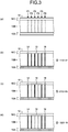
- Figs. 3A to 3D are partially enlarged explanatory views each illustrating a recording medium according to the modification of the first embodiment, as seen from its end face.
- the information recording position P1 serves as the recording position of a start flag 14 that indicates the record starting position of information.
- the information recording position P6 serves as the recording position of an end flag 16 that indicates the record ending position of the information.
- the four information recording positions P2 to P5 serve as information recording positions that can each record information of one bit, and thus record a code expressed by four bits as a whole.
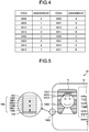
- Fig. 4 is an explanatory diagram of a correlation table of an information record example according to the modification of the first embodiment.
- any one of 16 codes (0 to F in hexadecimal), each expressed by four bits as information, can be recorded at the information recording positions P2 to P5 as an information code 15.
- the information recording position P1 always has a line recorded as the start flag 14, and the information recording position P6 always has a line recorded as the end flag 16.
- the information recording position P2 has a line
- the information recording position P3 has a line
- the information recording position P4 has a line
- the value of the information code 15 recorded here is "F" from the table of Fig. 4 .
- the information recording position P2 has no line
- the information recording position P3 has a line
- the information recording position P4 has no line
- the value of the information code 15 recorded here is "5" from the table of Fig. 4 .
- the information recording position P2 has a line
- the information recording position P3 has no line
- the information recording position P4 has no line
- the value of the information code 15 recorded here is "9" from the table of Fig. 4 .
- the line width of the line 13X may be made as thin as to be invisible to human unaided eyes.
- the thickness of the line 13X is preferably set to about 85 ⁇ m or less, which is equal to or less than 300 lines per inch (lpi).
- the line width in recording may be arbitrarily determined in consideration of the performance of a printing apparatus (recording apparatus) and the convenience of the authenticity determination.
- the line width of the line 13X is not limited to the example described above.
- the line 13X is used for the background in the image recording area and has a line width of 85 ⁇ m, and the image formation region 11 has a size of, for example, 20 mm ⁇ 27.5 mm, about 240 lines 13X can be recorded even in the case of the width 20 mm.
- information of 32 digits can be recorded.
- the thickness of the color development layer 10B is preferably set to 1 ⁇ m or more and 700 ⁇ m or less. This is because, if the thickness of the color development layer 10B is smaller than 1 ⁇ m, it becomes difficult to perform observation on the end face 10X of the recording medium 10 by using a simple magnifying glass, such as a loupe. On the other hand, if the thickness of the color development layer 10B is larger than 700 ⁇ m, the recording medium 10 come to exceed a thickness of 0.7 mm, which is the thickness of standard cards, such as a credit card.
- the thickness of the color development layer 10B is more preferably set to 20 ⁇ m or less. This is because, where this thickness is 20 ⁇ m or less, the line thickness at the end face 10X of the recording medium 10 becomes 20 ⁇ m or less, which is not larger than the diameter of dots formed by a general and inexpensive printer, such as an inkjet printer. In this case, forgery by printing on the end face 10X becomes difficult and expensive, and thus the falsification preventing effect is enhanced.
- the recording medium 10 includes the substrate 10A, the color development layer 10B, and the protection layer 10C serving as a surface layer.
- the substrate 10A may be made by using polyethylene terephthalate (PET), polyvinyl chloride (PVC), polycarbonate (PC), polyester, and/or the like, which are generally used as a card material, paper material, and/or film material.
- PET polyethylene terephthalate
- PVC polyvinyl chloride
- PC polycarbonate
- polyester and/or the like, which are generally used as a card material, paper material, and/or film material.
- a material usable for the substrate 10A may be exemplified by paper (form paper) materials and resin materials disclosed in Japanese Patent No. 3889431 , Japanese Patent No. 4215817 , Japanese Patent No. 4329744 , and Japanese Patent No. 4391286 .
- the usable material may be exemplified by polyethylene terephthalate (A-PET, PETG), polycyclohexane 1,4-dimethyl phthalate(PCT), polystyrene (PS), polymethyl methacrylate (PMMA), transparent ABS (MABS), polypropylene (PP), polyethylene (PE), polyvinyl alcohol (PVA), styrene butadiene copolymer (SBR), acrylic resins, acrylic modified urethane resins, styrene/acrylic resins, ethylene/acrylic resins, urethane resins, rosin modified maleic acid resins, vinyl chloride/vinyl acetate copolymer, polyvinyl acetal resins, polyamide resins, cellulose resins, such as hydroxyethyl cellulose, hydroxypropyl cellulose, and nitrocellulose, polyolefin resins, polyamide resins, other resins, such as biodegradable resins and cellulose resins,
- the "transparent” means that the light transmittance in the visible light region is 30% or more on average in the visible light region.
- the color development layer 10B may be made by using any one of the resins described for the substrate 10A together with an energy absorber selected from those disclosed in Japanese Patent No. 3889431 , Japanese Patent No. 4215817 , Japanese Patent No. 4329744 , and Japanese Patent No. 4391286 , such that 0.001 to 5 parts by weight of the energy absorber is contained with respect to 100 parts by weight of the resin.
- the energy absorber may be made by using at least one selected from the group consisting of carbon black, single metal, metal salt, metal hydroxide, metal oxide, metal sulfide, carbonate, and metal silicate.
- the single metal usable as the energy absorber may be exemplified by iron, zinc, tin, nickel, copper, silver, gold, and the like.
- the metal salt usable as the energy absorber may be exemplified by copper carbonate, nickel carbonate, manganese carbonate, cobalt carbonate, lanthanum carbonate, magnesium nitrate, manganese nitrate, iron nitrate, cadmium nitrate, zinc nitrate, cobalt nitrate, lead nitrate, nickel nitrate, copper nitrate, palladium nitrate, lanthanum nitrate, magnesium acetate, manganese acetate, cadmium acetate, zinc acetate, cobalt acetate, lead acetate, nickel acetate, copper acetate, palladium acetate, copper chloride, iron chloride, cobalt chloride, nickel chloride, silver chloride, zinc chloride, copper phosphate, iron phosphate, cobalt phosphate, copper pyrophosphate, copper sulfate, iron sulfate, cobalt sulfate, copper o
- the metal hydroxide usable as the energy absorber may be exemplified by copper hydroxide, aluminum hydroxide, magnesium hydroxide, zinc hydroxide, antimony hydroxide, cobalt hydroxide, nickel hydroxide, iron hydroxide, lanthanum hydroxide, and the like.
- the metal oxide may be exemplified by zinc oxide, magnesium oxide, aluminum oxide, alumina, iron oxide, iron black, titanium oxide, silicon oxide, antimony trioxide, cobalt oxide, lead oxide, tin oxide, indium oxide, manganese oxide, molybdenum oxide, nickel oxide, copper oxide, palladium oxide, lanthanum oxide, antimony-doped tin oxide(ATO), indium-doped tin oxide (ITO), synthetic zeolite, natural zeolite, copper-molybdenum complex oxide (42-903A, made by Tokan Material Technology Co., Ltd.), and the like.
- the metal oxide usable as the energy absorber may be further exemplified by mica, montmorillonite, smectite, and the like, which have a layered structure.
- the metal sulfide usable as the energy absorber may be exemplified by zinc sulfide, cadmium sulfide, and the like.
- the carbonate usable as the energy absorber may be exemplified by calcium carbonate or the like.
- the metal silicate may be exemplified by alumina silicate, alumina silicate containing iron (mica), hydrous alumina silicate (kaolin), magnesium silicate (talc), calcium silicate, magnesium silicate, and the like.
- the energy absorber may be replaced by alternatively using a temperature indicating material, such as a leuco colorant, leuco pigment, or the like, that makes color development at a temperature above a certain threshold.
- a temperature indicating material such as a leuco colorant, leuco pigment, or the like
- a color developer may be used as the temperature indicating material, which can be any acidic substance used as an electron acceptor in a thermosensitive recording body.
- the color developer may be exemplified by inorganic substances, such as activated clay and acid clay, inorganic acids, aromatic carboxylic acids, their anhydrides or metal salts thereof, organic color developers, such as organic sulfonic acids, other organic acids, and phenolic compounds, and the like. Of them, a phenolic compound is preferably used.
- the color developer may be exemplified by bis3-allyl-4-hydroxyphenylsulfone, polyhydroxystyrene, zinc salt of 3,5-di-t-butylsalicylic acid, zinc salt of 3-octyl-5-methylsalicylic acid, phenol, phenolic compounds, such as 4-phenylphenol, 4-hydroxyacetophenone, 2,2'-dihydroxydiphenyl, 2,2'-methylenebis(4-chlorophenol), 2,2'-methylenebis(4-methyl-6-t-butylphenol), 4,4'-isopropylidenediphenol(an alias is bisphenol A), 4,4'-isopropylidenebis(2-chlorophenol), 4,4'-isopropylidenebis(2-methylphenol), 4,4'-ethylenebis(2-methylphenol), 4,4'-thiobis(6-t-butyl-3-methylphenol), 1,1-bis(4-hydroxyphenyl)-cyclohexane, 2, 2,4
- the protection layer 10C may be made by using polyethylene terephthalate (PET), polyvinyl chloride (PVC), polycarbonate (PC), polyester, and/or the like, which are generally used as a card material, paper material, and/or film material. Further, a material usable for the protection layer 10C, other than those described above, may be exemplified by paper materials and resin materials disclosed in Japanese Patent No. 3889431 , Japanese Patent No. 4215817 , Japanese Patent No. 4329744 , and Japanese Patent No. 4391286 .
- the usable material may be exemplified by polyethylene terephthalate (A-PET, PETG), polycyclohexane 1,4-dimethyl phthalate(PCT), polystyrene (PS), polymethyl methacrylate (PMMA), transparent ABS (MABS), polypropylene (PP), polyethylene (PE), polyvinyl alcohol (PVA), styrene butadiene copolymer (SBR), acrylic resins, acrylic modified urethane resins, styrene/acrylic resins, ethylene/acrylic resins, urethane resins, rosin modified maleic acid resins, vinyl chloride/vinyl acetate copolymer, polyvinyl acetal resins, polyamide resins, cellulose resins, such as hydroxyethyl cellulose, hydroxypropyl cellulose, and nitrocellulose, polyolefin resins, polyamide resins, other resins, such as biodegradable resins and cellulose resins,
- the protection layer 10C needs to allow the content recorded on the color development layer 10B to be visually recognized, and thus is preferably made by using a transparent resin.
- the "transparent” means that the light transmittance in the visible light region is 30% or more on average in the visible light region.
- the protection layer 10C needs to be made of a material that transmits light in the wavelength region of the laser beam to be used.
- this wavelength region covers a wavelength of 1,064 nm of a YAG or YVO 4 laser, and wavelengths of 532 nm, 355 nm, and 266 nm of its harmonic.
- the protection layer 10C needs to be made of a material that transmits light within a certain range, such as a wavelength region of 700 to 1,200 nm.
- the first embodiment described above relates to a case where the color development layer 10B is formed of a single layer.
- the second embodiment relates to a case where the color development layer 10B includes a plurality of color development layers different in color.
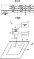
- Fig. 5 is a detailed configuration explanatory diagram of a recording medium according to the second embodiment.
- the colors of the plurality of color development layers for example, the three primary colors in printing, such as cyan (C), magenta (M), and yellow (Y), may be used.
- the overview of the print face according to the second embodiment is substantially the same as that of Fig. 1 according to the first embodiment, but a plurality of colors are observed in a cross-section of the medium as illustrated in Fig. 5 .
- heat i.e., temperature
- the temperatures of the respective layers are changed.
- the way of heat application by the laser is used to control such temperature changes of the layers, i.e., the irradiation conditions of the laser are used to control the temperatures of the plurality of color development layers, and thereby to control color development therein.
- the recording medium 10 includes a substrate 10A, on which a low temperature color development layer 10BL, a first spacer layer 10BS1, a middle temperature color development layer 10BM, a second spacer layer 10BS2, a high temperature color development layer 10BH, a functional layer 10F, and a protection layer 10C are laminated in this order.
- the low temperature color development layer 10BL, the middle temperature color development layer 10BM, and the high temperature color development layer 10BH serve as thermosensitive recording layers for image recording
- the first spacer layer 10BS1 and the second spacer layer 10BS2 serve as intermediate layers for heat insulation and heat conduction.
- the substrate 10A holds the low temperature color development layer 10BL, the first spacer layer 10BS1, the middle temperature color development layer 10BM, the second spacer layer 10BS2, the high temperature color development layer 10BH, the functional layer 10F, and the protection layer 10C.
- the low temperature color development layer 10BL is a layer containing a temperature indicating material made of a thermosensitive material that makes color development when its temperature becomes a first threshold temperature T1 or more.
- the first threshold temperature T1 of the low temperature color development layer 10BL is set to a range of 60°C to 140°C, for example.
- the first spacer layer 10BS1 is a layer that provides a thermal barrier when the low temperature color development layer 10BL is set in a non color development state, to suppress the heat conduction from the middle temperature color development layer 10BM side to the low temperature color development layer 10BL.
- the middle temperature color development layer 10BM is a layer containing a temperature indicating material made of a thermosensitive material that makes color development when its temperature becomes a second threshold temperature Tm (>T1) or more.
- the second threshold temperature Tm of the middle temperature color development layer 10BM is set to a range of 100°C to 200°C, for example.
- the second spacer layer 10BS2 is a layer that provides a thermal barrier when the middle temperature color development layer 10BM is set in a non color development state, to suppress the heat conduction from the high temperature color development layer 10BH side to the middle temperature color development layer 10BM.
- the high temperature color development layer 10BH is a layer containing a temperature indicating material made of a thermosensitive material that makes color development when its temperature becomes a third threshold temperature Th (>Tm) or more.
- the third threshold temperature Th of the high temperature color development layer 10BH is set to a range of 150°C to 270°C, for example.
- the functional layer 10F is a layer provided in accordance with a necessary function.
- the function of the functional layer 10F may be exemplified by insertion of a forgery prevention item, such as a hologram, lenticular lens, microarray lens, or ultraviolet excitation type fluorescent ink, insertion of an internal protection item, such as an ultraviolet cut layer, and insertion of both functions.
- a forgery prevention item such as a hologram, lenticular lens, microarray lens, or ultraviolet excitation type fluorescent ink
- an internal protection item such as an ultraviolet cut layer
- the protection layer 10C is a layer that protects the low temperature color development layer 10BL, the first spacer layer 10BS1, the middle temperature color development layer 10BM, the second spacer layer 10BS2, the high temperature color development layer 10BH, and the functional layer 10F.
- Figs. 6A to 6C are explanatory diagrams of the color development principle in monochromatic color development according to the second embodiment.
- FIG. 6A to 6C omit illustration of the functional layer 10F for ease of understanding.
- Fig. 6A is an explanatory diagram of the principle in a case where the low temperature color development layer 10BL is individually caused to make color development.
- Fig. 6B is an explanatory diagram of the principle in a case where the middle temperature color development layer 10BM is individually caused to make color development.
- Fig. 6C is an explanatory diagram of the principle in a case where the high temperature color development layer 10BH is individually caused to make color development.
- Figs. 7A to 7C are explanatory diagrams of temperature control in monochromatic color development according to the second embodiment.
- Fig. 7A is an explanatory diagram of the temperature control in a case where the low temperature color development layer 10BL is individually caused to make color development.
- the temperature of the front face 10S of the recording medium 10 is indicated by a temperature TPS.
- Fig. 7B is an explanatory diagram of the temperature control in a case where the middle temperature color development layer 10BM is individually caused to make color development.
- Fig. 7C is an explanatory diagram of the temperature control in a case where the high temperature color development layer 10BH is individually caused to make color development.
- the laser irradiation conditions are set to further realize that the temperature TPM of the middle temperature color development layer 10BM is prevented from exceeding the second threshold temperature Tm, and the temperature TPH of the high temperature color development layer 10BH is prevented from exceeding the third threshold temperature Th. Accordingly, the recording in this case is performed under the laser irradiation conditions thus set, i.e., under the temperature control state illustrated in Fig. 7A .
- the low temperature color development layer 10BL makes color development at its color development region AL.
- the laser irradiation conditions are set to further realize that the temperature TPH of the high temperature color development layer 10BH is prevented from exceeding the third threshold temperature Th, and heat conduction is suppressed by the first spacer layer 10BS1, by which the temperature TPL of the low temperature color development layer 10BL is prevented from exceeding the first threshold temperature Tl. Accordingly, the recording in this case is performed under the laser irradiation conditions thus set, i.e., under the temperature control state illustrated in Fig. 7B .
- the middle temperature color development layer 10BM makes color development at its color development region AM.
- the laser irradiation conditions are set to further realize that heat conduction is suppressed by the second spacer layer 10BS2 and the first spacer layer 10BS1, by which the temperature of the middle temperature color development layer 10BM is prevented from exceeding the second threshold temperature Tm, and the temperature of the low temperature color development layer 10BL is prevented from exceeding the first threshold temperature Tl.
- the recording in this case is performed under the laser irradiation conditions thus set, i.e., under the temperature control state illustrated in Fig. 7C .
- the high temperature color development layer 10BH makes color development at its color development region AH.
- Fig. 8 is an explanatory diagram of an example of laser irradiation conditions.
- power densities PDl, PDm, and PDh and recording times tl, tm, and th denote the power densities and the recording times for causing the low temperature color development layer 10BL, the middle temperature color development layer 10BM, and the high temperature color development layer 10BH to make color development, respectively.
- these parameters are set to satisfy the following conditions. PDl ⁇ PDm ⁇ PDh , and th ⁇ tm ⁇ tl
- the power density PD1 is set as the smallest value relatively, and the recording time tl is set as the largest value relatively.
- the temperature of the low temperature color development layer 10BL can exceed the first threshold temperature Tl, while, in the phase where heat is conducted to the high temperature color development layer 10BH and the middle temperature color development layer 10BM, the temperature of the middle temperature color development layer 10BM does not exceed the second threshold temperature Tm, and the temperature of the high temperature color development layer 10BH does not exceed the third threshold temperature Th.
- the power density PDh is set as the largest value relatively, and the recording time th is set as the smallest value relatively.
- the middle temperature color development layer 10BM does not exceed its threshold temperature, and the low temperature color development layer 10BL does not exceed its threshold temperature.
- the power density PDm and the recording time tm are set as intermediate values relatively, as described above.
- the middle temperature color development layer 10BM can exceed its threshold temperature, while, in the phase where heat is conducted to the high temperature color development layer 10BH and the low temperature color development layer 10BL, the high temperature color development layer 10BH does not exceed its threshold temperature, and the low temperature color development layer 10BL does not exceed its threshold temperature.
- the respective layers corresponding to the three primary colors can be selectively caused to make color development, and thus full-color recording can be performed by combining the three primary colors.
- the three primary colors can be recorded in a superimposed state in the lamination direction of the respective layers of the recording medium 10. Consequently, as compared with a case where the three primary colors are arranged separately along the two-dimensional plane, a well-looking image can be provided even by a relatively low resolution.
- Fig. 9 is a schematic configuration block diagram of a laser recording apparatus according to an embodiment.
- the laser recording apparatus 100 includes a laser head unit 102 configured to emit a laser beam LB for recording to a recording medium 10 mounted on a recording stage 101, a drive unit 103 configured to drive the recording stage 101 to perform scanning effectively by the laser beam LB emitted from the laser head unit 102, and a control unit 104 formed of a microcomputer configured to control the laser head unit 102 and the drive unit 103 on the basis of recording image data input from outside.
- the laser head unit 102 includes a spot control part 102A formed of an optical system configured to control the focus position of the laser beam LB and the spot diameter of the laser beam LB, under the control of the control unit 104.
- control unit 104 controls the power density, irradiation time, focus position, spot diameter, and so forth of the laser beam LB to be emitted from the laser head unit 102, to cause a desired one or plurality of color development layers to make color development, among the low temperature color development layer 10BL, the middle temperature color development layer 10BM, and the high temperature color development layer 10BH.
- Fig. 10 is an explanatory diagram of the relation between an energy amount and an input time for each color development layer to make color development alone.
- a region AL indicates a region that satisfies the energy amount and the input time for causing the low temperature color development layer 10BL to make color development alone.
- a region AM indicates a region that satisfies the energy amount and the input time for causing the middle temperature color development layer 10BM to make color development alone.
- a region AH indicates a region that satisfies the energy amount and the input time for causing the high temperature color development layer 10BH to make color development alone.
- the second embodiment for the purpose of improving the falsification preventing effect and the accuracy of authenticity determination, it is possible to perform coding to embed specific information by changing the arrangement of lines 13X extending up to the end face 10X of the recording medium 10, and/or by changing the color development layers to be caused to make color development, for every medium.
- Figs. 11A to 11D are explanatory views of code assignment according to a first aspect of the second embodiment.
- FIG. 11A to 11D illustrates a partially enlarged explanatory view of a recording medium subjected to code assignment according to the first aspect of the second embodiment, as seen from its end face.
- information recording positions P1 to P6 at six positions, for example, are set in each of the low temperature color development layer 10BL, the middle temperature color development layer 10BM, and the high temperature color development layer 10BH of the recording medium 10.
- the information recording position P1 serves as the recording position of a start flag 14 that indicates the record starting position of information.
- the information recording position P6 serves as the recording position of an end flag 16 that indicates the record ending position of the information.
- the four information recording positions P2 to P5 serve as information recording positions that can each record information of one bit, and thus record a code expressed by four bits as a whole.
- information code reading is performed in a direction from left to right as illustrated in Fig. 11A .
- Fig. 12 is an explanatory diagram of a correlation table of an information record example in the code assignment according to the first aspect of the second embodiment.
- any one of 16 codes (0 to F in hexadecimal), each expressed by four bits, can be recorded at the information recording positions P2 to P5 as an information code 15, and the cords in the respective layers correspond to the same code.
- a single code is recorded as a whole in the low temperature color development layer 10BL, the middle temperature color development layer 10BM, and the high temperature color development layer 10BH of the recording medium 10.
- the information recording position P2 has a line
- the information recording position P3 has a line
- the information recording position P4 has a line
- the value of the information code 15 recorded here is "F" from the table of Fig. 12 .
- the information recording position P2 has no line
- the information recording position P3 has a line
- the information recording position P4 has no line
- the value of the information code 15 recorded here is "5" from the table of Fig. 12 .
- the information recording position P2 has a line
- the information recording position P3 has no line
- the information recording position P4 has no line
- the value of the information code 15 recorded here is "9" from the table of Fig. 12 .
- an ID number (“12345678" in the example of Fig. 1 ) that can specify the owner of the recording medium 10 may be recorded, as in the first embodiment.
- start flag 14 and the end flag 16 only need to serve as marks for indicating embedment of the information code 15 between the flags, and thus may be formed with any color (single color or mixed color) as long as the drawing of lines can be recognized.
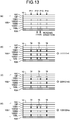
- Figs. 13A to 13D are explanatory views of code assignment according to a second aspect of the second embodiment.
- FIG. 13A to 13D illustrates a partially enlarged explanatory view of a recording medium subjected to code assignment according to the second aspect of the second embodiment, as seen from its end face.
- information recording positions P11 to P14 at four positions, for example, are set in each of the low temperature color development layer 10BL, the middle temperature color development layer 10BM, and the high temperature color development layer 10BH of the recording medium 10.
- the information recording position P11 serves as the recording position of a start flag 14 that indicates the record starting position of information.
- the information recording position P14 serves as the recording position of an end flag 16 that indicates the record ending position of the information.
- the two sets of information recording positions P12 and P13 serve as information recording positions that can each record information of three bits, and thus record a code expressed by six bits as a whole.
- information code reading is performed as illustrated in Fig. 13A , which is as follows. First, reading is performed to the information recording positions P12 in a direction from top to bottom, as in the order of the high temperature color development layer 10BH, to the middle temperature color development layer 10BM, and to the low temperature color development layer 10BL. Then, reading is performed to the information recording positions P13 in a direction from top to bottom, as in the order of the high temperature color development layer 10BH, to the middle temperature color development layer 10BM, and to the low temperature color development layer 10BL.
- Fig. 14 is an explanatory diagram of a correlation table of an information record example in the code assignment according to the second aspect of the second embodiment.
- the information recording position P12 of the high temperature color development layer 10BH has a line
- the information recording position P12 of the middle temperature color development layer 10BM has a line
- the information recording position P12 of the low temperature color development layer 10BL has a line
- the information recording position P13 of the high temperature color development layer 10BH has a line
- the information recording position P13 of the middle temperature color development layer 10BM has a line
- the information recording position P13 of the low temperature color development layer 10BL has a line
- the information recording position P12 of the high temperature color development layer 10BH has no line
- the information recording position P12 of the middle temperature color development layer 10BM has no line
- the information recording position P12 of the low temperature color development layer 10BL has no line
- the information recording position P13 of the high temperature color development layer 10BH has a line
- the information recording position P13 of the middle temperature color development layer 10BM has no line
- the information recording position P13 of the low temperature color development layer 10BL has a line
- the information recording position P12 of the high temperature color development layer 10BH has a line
- the information recording position P12 of the middle temperature color development layer 10BM has no line
- the information recording position P12 of the low temperature color development layer 10BL has no line
- the information recording position P13 of the high temperature color development layer 10BH has a line
- the information recording position P13 of the middle temperature color development layer 10BM has no line
- the value of the information code 15 recorded here is "a" from the table of Fig. 14 .
- Figs. 15A to 15D are explanatory views of code assignment according to a third aspect of the second embodiment.
- the third aspect differs in that the third aspect does not use the start flag 14 and the end flag 16 used in the first aspect and the second aspect.
- FIG. 15A to 15D illustrates a partially enlarged explanatory view of a recording medium subjected to code assignment according to the third aspect of the second embodiment, as seen from its end face.
- information recording positions P21 and P22 at two positions are set in each of the low temperature color development layer 10BL, the middle temperature color development layer 10BM, and the high temperature color development layer 10BH of the recording medium 10.
- the two set of information recording positions P21 and P22 serve as information recording positions that can each record information of three bits, and thus record a code expressed by six bits as a whole.
- information code reading is performed as illustrated in Fig. 15A , which is as follows. First, reading is performed to the information recording positions P21 in a direction from top to bottom, as in the order of the high temperature color development layer 10BH, to the middle temperature color development layer 10BM, and to the low temperature color development layer 10BL. Then, reading is performed to the information recording positions P22 in a direction from top to bottom, as in the order of the high temperature color development layer 10BH, to the middle temperature color development layer 10BM, and to the low temperature color development layer 10BL.
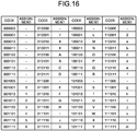
- Fig. 16 is an explanatory diagram of a correlation table of an information record example in the code assignment according to the third aspect of the second embodiment.
- the information recording position P21 of the high temperature color development layer 10BH has a line
- the information recording position P21 of the middle temperature color development layer 10BM has a line
- the information recording position P21 of the low temperature color development layer 10BL has a line
- the information recording position P22 of the high temperature color development layer 10BH has a line
- the information recording position P22 of the middle temperature color development layer 10BM has a line
- the information recording position P22 of the low temperature color development layer 10BL has a line
- the information code 15 "111111” stands.
- the value of the information code 15 recorded here is "m" from the table of Fig. 16 .
- the information recording position P21 of the high temperature color development layer 10BH has a line
- the information recording position P21 of the middle temperature color development layer 10BM has no line
- the information recording position P21 of the low temperature color development layer 10BL has no line
- the information recording position P22 of the high temperature color development layer 10BH has a line
- the information recording position P22 of the middle temperature color development layer 10BM has no line
- the information recording position P22 of the low temperature color development layer 10BL has a line
- the information code 15 "100101" stands.
- the information recording position P21 of the high temperature color development layer 10BH has a line
- the information recording position P21 of the middle temperature color development layer 10BM has no line
- the information recording position P21 of the low temperature color development layer 10BL has no line
- the information recording position P22 of the high temperature color development layer 10BH has a line
- the information recording position P22 of the middle temperature color development layer 10BM has no line
- the information recording position P22 of the low temperature color development layer 10BL has no line
- the information code 15 "100100" stands.
- the value of the information code 15 recorded here is "O" from the table of Fig. 16 .
- Figs. 17A to 17D are explanatory views of code assignment according to a fourth aspect of the second embodiment.
- the fourth aspect also does not use the start flag 14 and the end flag 16, as in the third aspect.
- FIG. 17A to 17D illustrates a partially enlarged explanatory view of a recording medium subjected to code assignment according to the fourth aspect of the second embodiment, as seen from its end face.
- information recording positions P21 and P22 at two positions are set in each of the low temperature color development layer 10BL, the middle temperature color development layer 10BM, and the high temperature color development layer 10BH of the recording medium 10.
- the two set of information recording positions P21 and P22 serve as information recording positions that can each record information of three bits, and thus record a code expressed by six bits as a whole.
- information code reading is performed as illustrated in Fig. 17A , which is as follows. First, reading is performed to the information recording positions P21 in a direction from bottom to top, as in the order of the low temperature color development layer 10BL, to the middle temperature color development layer 10BM, and to the high temperature color development layer 10BH. Then, reading is performed to the information recording positions P22 in a direction from bottom to top, as in the order of the low temperature color development layer 10BL, to the middle temperature color development layer 10BM, and to the high temperature color development layer 10BH.
- Fig. 18 is an explanatory diagram of a correlation table of an information record example in the code assignment according to the fourth aspect of the second embodiment.
- the information recording position P21 of the low temperature color development layer 10BL has no line
- the information recording position P21 of the middle temperature color development layer 10BM has a line
- the information recording position P21 of the high temperature color development layer 10BH has a line
- the information recording position P22 of the low temperature color development layer 10BL has a line
- the information recording position P22 of the middle temperature color development layer 10BM has a line
- the information recording position P22 of the high temperature color development layer 10BH has a line
- the information code 15 "011111" stands.
- the information recording position P21 of the low temperature color development layer 10BL has no line
- the information recording position P21 of the middle temperature color development layer 10BM has no line
- the information recording position P21 of the high temperature color development layer 10BH has a line
- the information recording position P22 of the low temperature color development layer 10BL has a line
- the information recording position P22 of the middle temperature color development layer 10BM has no line
- the information recording position P22 of the high temperature color development layer 10BH has a line
- the information code 15 "001101" stands.
- the value of the information code 15 recorded here is "6" from the table of Fig. 18 .
- the information recording position P21 of the low temperature color development layer 10BL has no line
- the information recording position P21 of the middle temperature color development layer 10BM has no line
- the information recording position P21 of the high temperature color development layer 10BH has a line
- the information recording position P22 of the low temperature color development layer 10BL has no line
- the information recording position P22 of the middle temperature color development layer 10BM has no line
- the value of the information code 15 recorded here is "0" from the table of Fig. 18 .
- Figs. 19A to 19C are explanatory diagrams (part 1) of temperature control in color mixing color development according to the second embodiment.
- the low temperature color development layer 10BL serves as a color development layer of cyan (C)
- the middle temperature color development layer 10BM serves as a color development layer of magenta (M)
- the high temperature color development layer 10BH serves as a color development layer of yellow (Y).
- Fig. 19A is an explanatory diagram of temperature control in a case where the middle temperature color development layer 10BM serving as a color development layer of magenta (M) and the high temperature color development layer 10BH serving as a color development layer of yellow (Y) are caused to make color development, so as to obtain color development of red (R).
- M magenta
- Y yellow
- R red
- Fig. 19B is an explanatory diagram of temperature control in a case where the low temperature color development layer 10BL serving as a color development layer of cyan (C) and the middle temperature color development layer 10BM serving as a color development layer of magenta (M) are caused to make color development, so as to obtain color development of blue (B).
- Fig. 19C is an explanatory diagram of temperature control in a case where the low temperature color development layer 10BL serving as a color development layer of cyan (C), the middle temperature color development layer 10BM serving as a color development layer of magenta (M), and the high temperature color development layer 10BH serving as a color development layer of yellow (Y) are caused to make color development, so as to obtain color development of black (K).
- C low temperature color development layer
- Y color development layer of yellow
- the laser irradiation conditions are set to realize that the temperature TPL of the low temperature color development layer 10BL is prevented from exceeding the first threshold temperature Tl, while the temperature TPM of the middle temperature color development layer 10BM exceeds the second threshold temperature Tm, and the temperature TPH of the high temperature color development layer 10BH exceeds the third threshold temperature Th.
- the recording in this case is performed under the laser irradiation conditions thus set, i.e., under a temperature control state where the laser irradiation time (horizontal axis) falls within a time zone TB as illustrated in Fig. 9A .
- the middle temperature color development layer 10BM serving as a color development layer of magenta (M) and the high temperature color development layer 10BH serving as a color development layer of yellow (Y) are caused to make color development, and color development of red (R) can thereby be obtained.
- the low temperature color development layer 10BL serving as a color development layer of cyan (C) and the middle temperature color development layer 10BM serving as a color development layer of magenta (M) are caused to make color development, so as to obtain color development of blue (B).
- the laser irradiation conditions are set to further realize that the temperature TPH of the high temperature color development layer 10BH is prevented from exceeding the third threshold temperature Th.
- the recording in this case is performed under the laser irradiation conditions thus set, i.e., under a temperature control state where the laser irradiation time (horizontal axis) falls within a time zone TB as illustrated in Fig. 19B .
- the low temperature color development layer 10BL serving as a color development layer of cyan (C) and the middle temperature color development layer 10BM serving as a color development layer of magenta (M) are caused to make color development, and color development of blue (B) can thereby be obtained.
- the low temperature color development layer 10BL serving as a color development layer of cyan (C)
- the middle temperature color development layer 10BM serving as a color development layer of magenta (M)
- the high temperature color development layer 10BH serving as a color development layer of yellow (Y) are caused to make color development, so as to obtain color development of black (K).
- the laser irradiation conditions are set to realize that heat is conducted from the laser irradiation position to the low temperature color development layer 10BL, by which the temperature TPL of the low temperature color development layer 10BL exceeds the first threshold temperature Tl, the temperature TPM of the middle temperature color development layer 10BM exceeds the second threshold temperature Tm, and the temperature TPH of the high temperature color development layer 10BH exceeds the third threshold temperature Th.
- the recording in this case is performed under the laser irradiation conditions thus set, i.e., under a temperature control state where the laser irradiation time (horizontal axis) falls within a time zone TB as illustrated in Fig. 19C .
- the low temperature color development layer 10BL serving as a color development layer of cyan (C)
- the middle temperature color development layer 10BM serving as a color development layer of magenta (M)
- the high temperature color development layer 10BH serving as a color development layer of yellow (Y) are caused to make color development, and color development of black (K) can thereby be obtained.
- Fig. 20 is an explanatory diagram (part 2) of temperature control in color mixing color development according to the second embodiment.
- Fig. 20 is an explanatory diagram of temperature control in a case where the low temperature color development layer 10BL serving as a color development layer of cyan (C) and the high temperature color development layer 10BH serving as a color development layer of yellow (Y), which are arranged by interposing therebetween the middle temperature color development layer 10BM serving as a color development layer of magenta (M), are caused to make color development, so as to obtain color development of green (G).
- C color development layer of cyan
- Y high temperature color development layer 10BH serving as a color development layer of yellow
- M magenta
- the temperature of the high temperature color development layer 10BH is first raised at once to make color development of yellow (Y), and then, in a state where the temperature of the middle temperature color development layer 10BM has become lower to some extent, the low temperature color development layer 10BL is caused to make color development alone by the temperature control as illustrated in Fig. 7A . Consequently, color development of green (G) can be obtained.
- Fig. 21 is a detailed configuration explanatory diagram of a recording medium according to the third embodiment.
- the lines 13A to 13E extending up to the end face 10X of a recording medium 10 are formed of extensions of lines composing the image background part 11A in the image formation region 11 of the recording medium 10.
- an edge portion of an image recorded in the image formation region 11 of the recording medium 10 is used for this purpose.
- an edge portion 11E1 corresponding to the border line between the subject's clothes and the background, and/or the subject's hair detected as an edge portion 11E2 are used.
- a line 13F or 13G (this line is formed of a single line or a plurality of lines) having a color the same as that of the corresponding edge portion is formed as an extension up to the end face 10X1 or 10X2 of the recording medium 10.
- the edge portion means a characteristic portion of the image, for example, a high contrast portion, such as the upper or lower end of the face, the end of the clothes or hair, or the face contour, in a face photo.
- a high contrast portion such as the upper or lower end of the face, the end of the clothes or hair, or the face contour, in a face photo.
- the extending positions of the lines 13F and 13G respectively extending up to the end faces 10X1 and 10X2 of the recording medium 10 vary depending on the image recorded in the image formation region 11.
- falsification such as replacement of the image
- the falsification resistance is improved.
- Fig. 22 is another detailed configuration explanatory diagram of a recording medium according to the third embodiment.
- extension lines 13F, 13G, 13H, and 131 may be arranged in both the longitudinal direction and the lateral direction of the recording medium 10, i.e., may extend up to both the end faces 10X1 and 10X2 of the recording medium 10.
- Fig. 23 is still another detailed configuration explanatory diagram of a recording medium according to the third embodiment.
- a high contrast edge portion such as a face contour
- a line extending up to the end face 10X1 or 10X2 of the recording medium 10 may be formed of a curved line in accordance with the shape of the edge portion, as illustrated in Fig. 23 .
- the positional relation between the eyes, the lips, or the like on a facial image is information important to recognize the identical person; therefore, recording extension lines at positions indirectly indicating the positions of such feature points is effective to prevent forgery, such as replacement of photos.
- Fig. 24 is still another detailed configuration explanatory diagram of a recording medium according to the third embodiment.
- Fig. 24 illustrates an example where lines extending from positions of the eyes (or line groups each including a plurality of lines) 13F1, 13G1, 13H1, and 13I1 extend in both the longitudinal direction and the lateral direction of the recording medium 10, i.e., extend up to both the end faces 10X1 and 10X2 of the recording medium 10.
- the lines 13F1 and 13G1 intersect at the position of the right eye on the facial image; and the lines 13H1 and 13I1 intersect at the position of the left eye on the facial image.
- Fig. 25 is still another detailed configuration explanatory diagram of a recording medium according to the third embodiment.
- Fig. 25 illustrates an example where lines extending from positions of the lips (or line groups each including a plurality of lines) 13F2, 13G2, 13H2, and 1312 extend in both the longitudinal direction and the lateral direction of the recording medium 10, i.e., extend up to both the end faces 10X1 and 10X2 of the recording medium 10.
- the lines 13F2 and 13G2 intersect at a position of the lips that can be seen when viewing the lips on the facial image from the right side of the face; and the lines 13H2 and 1312 intersect at a position of the lips that can be seen when viewing the lips on the facial image from the left side of the face.
- feature points eyes, lips, etc.
- the feature points are used individually in the explanations above, it is allowable to use, for the same recording medium 10, a plurality of feature points in combination.
- the extending positions of the lines 13F, 13G, 13F1, 13G1, 13H1, 13I1, 13F2, 13G2, 13H2, and 1312 each extending up to the end face 10X1 or 10X2 of the recording medium 10 vary depending on the image recorded in the image formation region 11. Thus, it becomes more difficult to make falsification or tampering to the print face of the recording medium 10.
- the color development layers are composed of three color development layers, which are the low temperature color development layer 10BL for making color development of cyan (C), the middle temperature color development layer 10BM for making color development of magenta (M), and the high temperature color development layer 10BH for making color development of yellow (Y).
- the fourth embodiment relates to a case using a recording medium that includes, in addition to the three color development layers, a ultra-low temperature color development layer 10BLL for making color development of black (K).
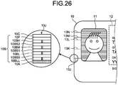
- Fig. 26 is a detailed configuration explanatory diagram of a recording medium according to the fourth embodiment.
- the temperatures of the respective layers are changed.
- the way of heat application by the laser is used to control such temperature changes of the layers, i.e., the irradiation conditions of the laser are used to control the temperatures of the plurality of color development layers, and thereby to control color development therein.
- the recording medium 10 includes a substrate 10A, on which a ultra-low temperature color development layer 10BLL, a 0th spacer layer 10BS0, a low temperature color development layer 10BL, a first spacer layer 10BS1, a middle temperature color development layer 10BM, a second spacer layer 10BS2, a high temperature color development layer 10BH, a functional layer 10F, and a protection layer 10C are laminated in this order. Further, a line 13J is recorded by these layers.
- a substrate 10A on which a ultra-low temperature color development layer 10BLL, a 0th spacer layer 10BS0, a low temperature color development layer 10BL, a first spacer layer 10BS1, a middle temperature color development layer 10BM, a second spacer layer 10BS2, a high temperature color development layer 10BH, a functional layer 10F, and a protection layer 10C are laminated in this order. Further, a line 13J is recorded by these layers.
- the ultra-low temperature color development layer 10BLL, the low temperature color development layer 10BL, the middle temperature color development layer 10BM, and the high temperature color development layer 10BH serve as thermosensitive recording layers for image recording
- the 0th spacer layer 10BS0, the first spacer layer 10BS1, and the second spacer layer 10BS2 serve as intermediate layers for heat insulation and heat conduction.
- the low temperature color development layer 10BL, the first spacer layer 10BS1, the middle temperature color development layer 10BM, the second spacer layer 10BS2, the high temperature color development layer 10BH, the functional layer 10F, the protection layer 10C, and the substrate 10A are the same as those of the second embodiment, and thus their detailed description will be omitted.
- the ultra-low temperature color development layer 10BLL is a layer containing a temperature indicating material made of a thermosensitive material that makes color development when its temperature becomes a 0th threshold temperature Tll or more.
- the 0th threshold temperature Tll of the ultra-low temperature color development layer 10BLL is set to a range of 40°C to 90°C, for example.
- the 0th spacer layer 10BS0 is a layer that provides a thermal barrier when the ultra-low temperature color development layer 10BLL is set in a non color development state, to suppress the heat conduction from the low temperature color development layer 10BL side to the ultra-low temperature color development layer 10BLL.
- the fourth embodiment for the purpose of improving the falsification preventing effect and the accuracy of authenticity determination, it is possible to perform coding to embed specific information by changing the arrangement of lines 13X extending up to the end face 10X of the recording medium 10, and/or by changing the color development layers to be caused to make color development, for every medium.
- Figs. 27A to 27D are explanatory views of code assignment according to a first aspect of the fourth embodiment.
- FIG. 27A to 27D illustrates a partially enlarged explanatory view of a recording medium subjected to code assignment according to the first aspect of the fourth embodiment, as seen from its end face.
- information recording positions P1 to P6 at six positions are set in each of the ultra-low temperature color development layer 10BLL, the low temperature color development layer 10BL, the middle temperature color development layer 10BM, and the high temperature color development layer 10BH of the recording medium 10.
- the information recording position P1 serves as the recording position of a start flag 14 that indicates the record starting position of information.
- the information recording position P6 serves as the recording position of an end flag 16 that indicates the record ending position of the information.
- the four information recording positions P2 to P5 serve as information recording positions that can each record information of one bit, and thus record a code expressed by four bits as a whole.
- information code reading is performed in a direction from left to right as illustrated in Fig. 27A .
- Fig. 28 is an explanatory diagram of a correlation table of an information record example in the code assignment according to the first aspect of the fourth embodiment.
- any one of 16 codes (0 to F in hexadecimal), each expressed by four bits, can be recorded at the information recording positions P2 to P5 as an information code 15, and the cords in the respective layers correspond to the same code.
- a single code is recorded as a whole in the ultra-low temperature color development layer 10BLL, the low temperature color development layer 10BL, the middle temperature color development layer 10BM, and the high temperature color development layer 10BH of the recording medium 10.
- the information recording position P2 has a line
- the information recording position P3 has a line
- the information recording position P4 has a line
- the value of the information code 15 recorded here is "F" from the table of Fig. 28 .
- the information recording position P2 has no line
- the information recording position P3 has a line
- the information recording position P4 has no line
- the value of the information code 15 recorded here is "5" from the table of Fig. 28 .
- the information recording position P2 has a line
- the information recording position P3 has no line
- the information recording position P4 has no line
- the value of the information code 15 recorded here is "9" from the table of Fig. 28 .
- an ID number (“12345678" in the example of Fig. 1 ) that can specify the owner of the recording medium 10 may be recorded, as in the first embodiment.
- start flag 14 and the end flag 16 only need to serve as marks for indicating embedment of the information code 15 between the flags, and thus may be formed with any color (single color or mixed color) as long as the drawing of lines can be recognized.
- Figs. 29A to 29D are explanatory views of code assignment according to a second aspect of the fourth embodiment.
- FIG. 29A to 29D illustrates a partially enlarged explanatory view of a recording medium subjected to code assignment according to the second aspect of the fourth embodiment, as seen from its end face.
- information recording positions P1 to P6 at six positions are set in the ultra-low temperature color development layer 10BLL, the low temperature color development layer 10BL, the middle temperature color development layer 10BM, and the high temperature color development layer 10BH of the recording medium 10.
- the ultra-low temperature color development layer 10BLL includes an information recording position P2 and an information recording position P4, to each of which one bit is assigned by the presence or absence of color development.
- the low temperature color development layer 10BL, the middle temperature color development layer 10BM, and the high temperature color development layer 10BH include an information recording position P3 and an information recording position P5, to each of which one bit is assigned by the presence or absence of color development as a whole (black (K) obtained by color mixing color development, or no color development).
- K black
- the result is always black (K) even though the color tone is different.
- the information code embedment is difficult to find, and thus provides a merit to improve the falsification resistance.
- information code reading is performed as illustrated in Fig. 29A , which is as follows. Specifically, reading is performed as in the order of the information recording position P2 of the ultra-low temperature color development layer 10BLL, to the information recording position P3 of the low temperature color development layer 10BL, the middle temperature color development layer 10BM, and the high temperature color development layer 10BH, to the information recording position P4 of the ultra-low temperature color development layer 10BLL, and to the information recording position P5 of the low temperature color development layer 10BL, the middle temperature color development layer 10BM, and the high temperature color development layer 10BH.
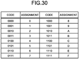
- Fig. 30 is an explanatory diagram of a correlation table of an information record example in the code assignment according to the second aspect of the fourth embodiment.
- any one of 16 codes (0 to F in hexadecimal), each expressed by four bits, can be recorded at the information recording positions P2 to P5 as an information code 15.
- the information recording position P2 of the ultra-low temperature color development layer 10BLL has a line
- the information recording position P3 of all the low temperature color development layer 10BL, the middle temperature color development layer 10BM, and the high temperature color development layer 10BH has a line
- the information recording position P4 of the ultra-low temperature color development layer 10BLL has a line
- the value of the information code 15 recorded here is "F" from the table of Fig. 30 .
- the information recording position P2 of the ultra-low temperature color development layer 10BLL has no line
- the information recording position P3 of all the low temperature color development layer 10BL, the middle temperature color development layer 10BM, and the high temperature color development layer 10BH has a line
- the information recording position P4 of the ultra-low temperature color development layer 10BLL has no line
- the value of the information code 15 recorded here is "5" from the table of Fig. 30 .
- the information recording position P2 of the ultra-low temperature color development layer 10BLL has a line
- the information recording position P3 of all the low temperature color development layer 10BL, the middle temperature color development layer 10BM, and the high temperature color development layer 10BH has no line
- the information recording position P4 of the ultra-low temperature color development layer 10BLL has no line
- the value of the information code 15 recorded here is "9" from the table of Fig. 30 .
- an ID number (“12345678" in the example of Fig. 1 ) that can specify the owner of the recording medium 10 may be recorded, as in the first embodiment.
- start flag 14 and the end flag 16 only need to serve as marks for indicating embedment of the information code 15 between the flags, and thus may be formed with any color (single color or mixed color) as long as the drawing of lines can be recognized.
- Figs. 31A to 31D are explanatory views of code assignment according to a third aspect of the fourth embodiment.
- FIG. 31A to 31D illustrates a partially enlarged explanatory view of a recording medium subjected to code assignment according to the third aspect of the fourth embodiment, as seen from its end face.
- information recording positions P21 and P22 at two positions are set in each of the ultra-low temperature color development layer 10BLL, the low temperature color development layer 10BL, the middle temperature color development layer 10BM, and the high temperature color development layer 10BH of the recording medium 10.
- the information recording positions P21 and P22 serve as information recording positions that can each record information of one bit, and thus record a code expressed by eight bits as a whole.
- information code reading is performed as illustrated in Fig. 31A , in which reading is performed to the information recording positions P21 in a direction from bottom to top, and then to the information recording positions P22 in a direction from bottom to top, so as to read a information code of eight bits as a whole.
- the information recording positions P21 and the information recording positions P22 also provide functions of a start flag and an end flag. Accordingly, the information code has been coded such that, with respect to either set of the information recording positions P21 and the information recording positions P22, any one of the ultra-low temperature color development layer 10BLL, the low temperature color development layer 10BL, the middle temperature color development layer 10BM, and the high temperature color development layer 10BH of the recording medium 10 is caused to make color development.
- Fig. 32 is an explanatory diagram of part (where the upper-order four bits are 0001) of a correlation table of an information record example in the code assignment according to the third aspect of the fourth embodiment.
- a layer with a line (line for security) to be formed in either one of the information recording position P21 and the information recording position P22 may be limited to only the high temperature color development layer 10BH closest to the surface layer. Then, as illustrated in Fig. 32 , for example, where the assignments are limited to 15 types, which is the total of ten numbers of 0 to 9 plus five symbols, the recording time (drawing time) of lines (lines for security) can be shortened.
- the information recording position P21 of the ultra-low temperature color development layer 10BLL has no line
- the information recording position P21 of the low temperature color development layer 10BL has no line
- the information recording position P21 of the middle temperature color development layer 10BM has no line
- the information recording position P21 of the high temperature color development layer 10BH has a line
- the information recording position P22 of the ultra-low temperature color development layer 10BLL has a line
- the information recording position P22 of the low temperature color development layer 10BL has a line
- the information recording position P22 of the middle temperature color development layer 10BM has a line
- the information recording position P22 of the high temperature color development layer 10BH has a line
- the information recording position P21 of the ultra-low temperature color development layer 10BLL has no line
- the information recording position P21 of the low temperature color development layer 10BL has no line
- the information recording position P21 of the middle temperature color development layer 10BM has no line
- the information recording position P21 of the high temperature color development layer 10BH has a line
- the information recording position P22 of the ultra-low temperature color development layer 10BLL has a line
- the information recording position P22 of the low temperature color development layer 10BL has no line
- the information recording position P22 of the middle temperature color development layer 10BM has a line
- the information recording position P22 of the high temperature color development layer 10BH has no line
- the information recording position P21 of the ultra-low temperature color development layer 10BLL has no line
- the information recording position P21 of the low temperature color development layer 10BL has no line
- the information recording position P21 of the middle temperature color development layer 10BM has no line
- the information recording position P21 of the high temperature color development layer 10BH has a line
- the information recording position P22 of the ultra-low temperature color development layer 10BLL has a line
- the information recording position P22 of the low temperature color development layer 10BL has no line
- the information recording position P22 of the middle temperature color development layer 10BM has no line
- the information recording position P22 of the high temperature color development layer 10BH has a line
- the information code 15 "00011001" stands.
- information of eight bits is used.
- an ID number (“12345678" in the example of Fig. 1 ) that can specify the owner of the recording medium 10 may be recorded, as in the first embodiment.
- the recording medium 10 includes the image formation region 11 in which an image is formed by color development of the ultra-low temperature color development layer 10BLL in addition to the low temperature color development layer 10BL, the middle temperature color development layer 10BM, and the high temperature color development layer 10BH, and lines 13 serving as lines for security reach the image formed in the image formation region 11.
- lines 13 serving as lines for security reach the image formed in the image formation region 11.
- Fig. 33 is an explanatory diagram of a recording medium according to a first aspect of the fifth embodiment.
- line groups (line groups for security) 13G1 to 13G4 each composed of a plurality of lines 13X, may be arranged such that the end portions opposite to the respective end faces 10X are positioned inside the image formation region 11.
- the presence or absence of a line for security, and an information code can be optically identified at any one of the end faces 10X. Further, the presence or absence of the line for security, and the information code, can also be optically identified from the front face 10S of the recording medium 10. Thus, confirmation of falsification becomes easier.
- Fig. 34 is an explanatory diagram of a recording medium according to a second aspect of the fifth embodiment.
- line groups (line groups for security) 13G1 to 13G4 each composed of a plurality of lines 13X, may be arranged such that the end portions opposite to the respective end faces 10X are set in contact with the image formation region 11.
- the presence or absence of a line for security, and an information code can be optically identified at any one of the end faces 10X. Further, the presence or absence of the line for security, and the information code, can also be optically identified from the front face 10S of the recording medium 10. Thus, confirmation of falsification becomes easier.
- Fig. 35 is an explanatory diagram of a recording medium according to a third aspect of the fifth embodiment.
- line groups (line groups for security) 13G1 to 13G4 each composed of a plurality of lines 13X, may be arranged such that the end portions opposite to the respective end faces 10X do not reach the image formation region 11.
- the presence or absence of a line for security, and an information code can be optically identified at any one of the end faces 10X, and the presence or absence of the line for security, and the information code, can also be optically identified from the front face of the recording medium 10.
- the sixth embodiment relates to a case where a recording medium 10 is configured such that the presence or absence of lines for security, and information codes, cannot be optically identified from the front face 10S of the recording medium 10.
- Fig. 36 is a schematic configuration view of a recording medium according to a sixth embodiment.
- Fig. 36 the constituent elements corresponding to those of the recording medium according to the fourth embodiment illustrated in Fig. 26 are denoted by the same reference symbols.
- the recording medium 10 according to the sixth embodiment differs from the recording medium 10 according to the fourth embodiment as follows. Specifically, a hiding layer 10G is laminated on the functional layer 10F to hide the presence of lines for security when the lines are observed from the front face 10S side of the recording medium 10. Further, the hiding layer 10G is provided with an opening WD that allows the recording contents in the image formation region 11 and/or the specific information recording area 12 to be visually recognized.
- Fig. 37 is an external view of the recording medium according to the sixth embodiment.
- an opening WD1 is formed as an opening WD that allows the recording contents in the image formation region 11 to be visually recognized
- an opening WD2 is formed as an opening WD that allows the recording contents in the specific information recording area 12 to be visually recognized.
- the seventh embodiment is different from the above embodiments in the method of embedding the information code as explained in the respective embodiments and in that a type, etc., of information to be read when the information code embedded is read is superimposed on the facial image and is recorded as invisible information.
- Fig. 38 is an explanatory diagram of a recording medium obtained by recording invisible information to the recording medium as illustrated in Fig. 1 .
- Fig. 39 is an explanatory diagram of a recording medium obtained by recording invisible information to the recording medium as illustrated in Fig. 21 .
- the followings are possible as a method of recording the invisible information 20: for example, a method of recording with a fluorescent material that is excited by ultraviolet light and glows, a method of recording using a thermosensitive material in which a hue changes at or around a threshold temperature, a method of making an ink with these materials and printing, a method that is a combination of a plurality of methods of these methods, or the like.
- Whether the recording medium 10 is authentic can be confirmed by confirming whether the invisible information 20 agrees with the information code embedded by a line extending up to the end face 10X1 or 10X2 of the recording medium 10 or whether the invisible information 20 has a correct correspondence relation (for example, whether the invisible information is bit invert data of the information code, two's complement data of the information code, hash data of the information code, or the like).
- the invisible information 20 may be formed with a fluorescent material that is excited by ultraviolet light and glows or may uses a thermosensitive material in which a hue changes at or around a threshold temperature. It is allowable to combine with a technique of making an ink with these materials and printing.
- the seventh embodiment relates to a specific example of an apparatus (checking apparatus) for confirming forgery or alteration on the basis of color development of the respective color development layers 10BLL, 10BL, 10BM, and 10BH.
- Fig. 40 is a schematic configuration block diagram of a checking apparatus.
- the checking apparatus 50 includes a reading unit 51 configured to read the color development states of the respective color development layers 10BLL, 10BL, 10BM, and 10BH from two end faces 10X of a recording medium 10, a control unit 52 configured to confirm forgery or alteration on the basis of images of the end faces 10X read by the reading unit 51, and a display unit 53 configured to display a checking result under the control of the control unit 52.
- the reading unit 51 includes an illumination part 51A that includes an LED or the like and emits illumination light, optical guide parts 51B and 51C for guiding illumination light emitted from the illumination part 51A to the respective corresponding end faces 10X of the recording medium 10, an imaging part (camera) 51D for picking up an image of the end face 10X of the recording medium 10 opposed to the optical guide part 51B, and an imaging part (camera) 51E for picking up an image of the end face 10X of the recording medium 10 opposed to the optical guide part 51C.
- an illumination part 51A that includes an LED or the like and emits illumination light
- optical guide parts 51B and 51C for guiding illumination light emitted from the illumination part 51A to the respective corresponding end faces 10X of the recording medium 10
- an imaging part (camera) 51D for picking up an image of the end face 10X of the recording medium 10 opposed to the optical guide part 51B
- an imaging part (camera) 51E for picking up an image of the end face 10X of the recording medium 10 opposed to the optical guide part 51
- control unit 52 may have a hardware configuration utilizing an ordinary computer, which includes a control device, such as an MPU, a storage device, such as a Read Only Memory (ROM) or RAM, an external storage device, such as an HDD or CD drive device, and an input device, such as a keyboard and/or mouse.
- a control device such as an MPU
- a storage device such as a Read Only Memory (ROM) or RAM
- ROM Read Only Memory
- RAM random access memory
- external storage device such as an HDD or CD drive device
- input device such as a keyboard and/or mouse.
- control unit 52 treats, as a checking object, an ID number ("12345678" in the case of Fig. 40 ) recorded in the specific information recording area 12, and the ID number is recorded by lines for security on the end faces 10X.
- a checking instruction is give to the checking apparatus 50, and the ID number recorded in the specific information recording area 12 is input.
- the input of the ID number recorded in the specific information recording area 12 is performed by using a character recognition device (not illustrated) to read the ID number recorded in the specific information recording area 12, or the input is performed manually.
- control unit 52 of the checking apparatus 50 controls the illumination part 51A to emit illumination light.
- the illumination light emitted by the illumination part 51A is guided by the optical guide parts 51B and 51C to the respective corresponding end faces 10X of the recording medium 10.
- the imaging part 51D picks up an image of the end face 10X of the recording medium 10 opposed to the optical guide part 51B, and outputs the image data to the control unit 52.
- the imaging part 51E picks up an image of the end face 10X of the recording medium 10 opposed to the optical guide part 51C, and outputs the image data to the control unit 52.
- control unit 52 detects, for example, a start flag 14 and an end flag 16 as described above, from each of the input pieces of image data, and then extracts the ID number on the basis of information codes 15, each of which is recorded between the start flag 14 and the end flag 16.
- this extracted ID number is compared with the input ID number, and the checking result thus obtained is displayed by the display unit 53.
- the seventh embodiment it is possible to easily read information from the end faces 10X of the recording medium 10, and to determine the authenticity of this recording medium 10.
- the respective color development layers corresponding to cyan (C), magenta (M), yellow (Y), and black (K) are caused to make color development by using a single laser beam source, such as a laser device with a wavelength of 2,000 nm or more, fiber laser device, CO 2 laser device, or semiconductor laser device.
- a single laser beam source such as a laser device with a wavelength of 2,000 nm or more, fiber laser device, CO 2 laser device, or semiconductor laser device.
- the color development layers corresponding to cyan (C), magenta (M), and yellow (Y) are caused to make color development by using a thermal head, laser device of a wavelength of 2,000 nm or more, fiber laser device, CO 2 laser device, or semiconductor laser device, while the color development layer corresponding to black (K) is caused to make color development by using a laser with a wavelength of 1,064 nm, such as a YAG laser device or YVO 4 laser device.
- the checking apparatus 50 is configured as a stationary type apparatus.
- a checking apparatus may be configured as a handy type apparatus (portable apparatus) by integrally constructing the reading unit 51, the control unit 52, and the display unit 53.
- a program to be executed by the control unit 52 according to the eighth embodiment may be provided in a state recorded in a computer readable recording medium, such as a CD-ROM, flexible disk (FD), CD-R, or Digital Versatile Disk (DVD), by a file in an installable format or executable format.
- a computer readable recording medium such as a CD-ROM, flexible disk (FD), CD-R, or Digital Versatile Disk (DVD)
- a program to be executed by the control unit 52 may be provided such that the program is stored in a computer connected to a network, such as the internet, and is downloaded via the network.
- a program to be executed by the control unit 52 may be prepared such that the program is provided or distributed via a network, such as the internet.
- a program to be executed by the control unit 52 according to the eighth embodiment may be provided in a state incorporated in an ROM or the like in advance.
Landscapes
- Physics & Mathematics (AREA)
- Engineering & Computer Science (AREA)
- General Physics & Mathematics (AREA)
- Theoretical Computer Science (AREA)
- General Chemical & Material Sciences (AREA)
- Chemical Kinetics & Catalysis (AREA)
- Optics & Photonics (AREA)
- Chemical & Material Sciences (AREA)
- Health & Medical Sciences (AREA)
- Electromagnetism (AREA)
- General Health & Medical Sciences (AREA)
- Toxicology (AREA)
- Manufacturing & Machinery (AREA)
- Credit Cards Or The Like (AREA)
Applications Claiming Priority (2)
| Application Number | Priority Date | Filing Date | Title |
|---|---|---|---|
| JP2017056347A JP6851873B2 (ja) | 2017-03-22 | 2017-03-22 | 記録媒体 |
| PCT/JP2018/011465 WO2018174178A1 (ja) | 2017-03-22 | 2018-03-22 | 記録媒体 |
Publications (3)
| Publication Number | Publication Date |
|---|---|
| EP3597444A1 true EP3597444A1 (de) | 2020-01-22 |
| EP3597444A4 EP3597444A4 (de) | 2021-01-13 |
| EP3597444B1 EP3597444B1 (de) | 2023-12-27 |
Family
ID=63584435
Family Applications (1)
| Application Number | Title | Priority Date | Filing Date |
|---|---|---|---|
| EP18771591.7A Active EP3597444B1 (de) | 2017-03-22 | 2018-03-22 | Aufzeichnungsmedium |
Country Status (4)
| Country | Link |
|---|---|
| US (1) | US20200094603A1 (de) |
| EP (1) | EP3597444B1 (de) |
| JP (1) | JP6851873B2 (de) |
| WO (1) | WO2018174178A1 (de) |
Families Citing this family (6)
| Publication number | Priority date | Publication date | Assignee | Title |
|---|---|---|---|---|
| JP7056060B2 (ja) * | 2017-10-03 | 2022-04-19 | 凸版印刷株式会社 | レーザーマーキング記録媒体の製造方法 |
| JP7178011B2 (ja) | 2018-10-10 | 2022-11-25 | 東芝インフラシステムズ株式会社 | 記録媒体及び記録装置 |
| JP7301777B2 (ja) | 2020-03-24 | 2023-07-03 | 株式会社東芝 | 感熱媒体及びレーザ記録装置 |
| JP7604157B2 (ja) * | 2020-09-29 | 2024-12-23 | キヤノン株式会社 | 画像処理装置、情報処理装置、記録方法およびプログラム |
| CN116438540A (zh) * | 2020-10-01 | 2023-07-14 | 恩图鲁斯特有限公司 | 使用元数据的打印色带残留图像加扰技术 |
| WO2024190816A1 (ja) * | 2023-03-13 | 2024-09-19 | 大日本印刷株式会社 | プログラム、情報処理方法及び情報処理装置 |
Family Cites Families (16)
| Publication number | Priority date | Publication date | Assignee | Title |
|---|---|---|---|---|
| DE1920513B2 (de) | 1969-04-23 | 1977-03-24 | Kuehlmoebel | |
| JPH076118A (ja) * | 1993-06-15 | 1995-01-10 | Nikon Corp | 周辺装置属性データ変更装置 |
| JPH0761181A (ja) * | 1993-08-26 | 1995-03-07 | Mitsubishi Paper Mills Ltd | 情報記録媒体 |
| JP2000127551A (ja) * | 1998-08-17 | 2000-05-09 | Fuji Photo Film Co Ltd | プリンタ及び記録用紙 |
| US6934043B1 (en) * | 1998-08-17 | 2005-08-23 | Fuji Photo Film Co., Ltd. | Printer and recording material for the same |
| JP4390377B2 (ja) | 2000-09-19 | 2009-12-24 | 大日本印刷株式会社 | 感熱印字記録媒体 |
| JP4391286B2 (ja) | 2004-03-26 | 2009-12-24 | 大日本印刷株式会社 | カ−ド基材 |
| JP4329744B2 (ja) | 2005-08-25 | 2009-09-09 | 東洋インキ製造株式会社 | 記録材および記録方法 |
| US7314216B2 (en) * | 2005-04-19 | 2008-01-01 | Xerox Corporation | Method for making a unique code onto a paper edge |
| JP3889431B1 (ja) | 2006-02-08 | 2007-03-07 | 日本カラリング株式会社 | レーザーマーキング用多層シート及びレーザーマーキング方法 |
| JP4215817B1 (ja) | 2008-05-26 | 2009-01-28 | 日本カラリング株式会社 | 電子パスポート用レーザーマーキング多層シート及び電子パスポート |
| EP2332738B1 (de) * | 2009-12-10 | 2012-07-04 | Agfa-Gevaert | Sicherheitsdokument mit Sicherheitsmerkmal auf Rand |
| JP2012083957A (ja) * | 2010-10-12 | 2012-04-26 | National Printing Bureau | 小切束及び小切束の判別方法 |
| JP2013071330A (ja) * | 2011-09-28 | 2013-04-22 | Toppan Forms Co Ltd | 情報カードおよびその製造方法 |
| JP2013107289A (ja) * | 2011-11-21 | 2013-06-06 | Dainippon Printing Co Ltd | 情報記録媒体 |
| DE102014015280A1 (de) * | 2014-10-16 | 2016-04-21 | Giesecke & Devrient Gmbh | Tragbarer Datenträger |
-
2017
- 2017-03-22 JP JP2017056347A patent/JP6851873B2/ja active Active
-
2018
- 2018-03-22 EP EP18771591.7A patent/EP3597444B1/de active Active
- 2018-03-22 WO PCT/JP2018/011465 patent/WO2018174178A1/ja not_active Ceased
- 2018-03-22 US US16/495,711 patent/US20200094603A1/en not_active Abandoned
Also Published As
| Publication number | Publication date |
|---|---|
| JP6851873B2 (ja) | 2021-03-31 |
| EP3597444B1 (de) | 2023-12-27 |
| EP3597444A4 (de) | 2021-01-13 |
| WO2018174178A1 (ja) | 2018-09-27 |
| JP2018160048A (ja) | 2018-10-11 |
| US20200094603A1 (en) | 2020-03-26 |
Similar Documents
| Publication | Publication Date | Title |
|---|---|---|
| EP3597444B1 (de) | Aufzeichnungsmedium | |
| CN113879024B (zh) | 身份证明 | |
| US20120127547A1 (en) | Image display and labeled article | |
| US11453231B2 (en) | Recording medium and recording device | |
| BRPI1014948B1 (pt) | processo para proteção de um documento de identificação e documento de identificação segura | |
| JP5637371B2 (ja) | 画像表示体、転写箔及びラベル付き物品 | |
| US20200117122A1 (en) | Recording medium and recording device | |
| JP5515713B2 (ja) | 画像表示体、転写箔及び個人認証媒体 | |
| EP4079816A1 (de) | Laminat, medium und verfahren | |
| JP2015123593A (ja) | 画像表示デバイス、画像表示デバイスの製造方法、および、転写リボン | |
| JP2021079562A (ja) | 記録媒体 | |
| JP7694581B2 (ja) | 積層体、冊子体、及び積層体を用いる方法 | |
| US9996792B2 (en) | Data carrier | |
| JP5589341B2 (ja) | 画像表示体、個人認証媒体、ブランク媒体、及び画像表示体の製造方法 | |
| US10471694B2 (en) | Laminate, method for producing laminate, and personal authentication medium | |
| JP7168919B1 (ja) | 情報表示媒体、冊子体、及び関連する方法 | |
| EP3763540A1 (de) | Verfahren zur herstellung einer karte | |
| JP2020152000A (ja) | レーザ記録装置および方法 | |
| JP2018187878A (ja) | 偽造防止カード及びその製造方法 | |
| EP4713210A1 (de) | Fühlbare latente informationen in einer tintenstrahldruckschicht auf identifikationskarten | |
| EP4713211A1 (de) | Latente information auf einer transparenten schicht auf ausweiskarten | |
| JP2021049728A (ja) | 真贋判定用カード及びその製造方法 |
Legal Events
| Date | Code | Title | Description |
|---|---|---|---|
| STAA | Information on the status of an ep patent application or granted ep patent |
Free format text: STATUS: THE INTERNATIONAL PUBLICATION HAS BEEN MADE |
|
| PUAI | Public reference made under article 153(3) epc to a published international application that has entered the european phase |
Free format text: ORIGINAL CODE: 0009012 |
|
| STAA | Information on the status of an ep patent application or granted ep patent |
Free format text: STATUS: REQUEST FOR EXAMINATION WAS MADE |
|
| 17P | Request for examination filed |
Effective date: 20191017 |
|
| AK | Designated contracting states |
Kind code of ref document: A1 Designated state(s): AL AT BE BG CH CY CZ DE DK EE ES FI FR GB GR HR HU IE IS IT LI LT LU LV MC MK MT NL NO PL PT RO RS SE SI SK SM TR |
|
| AX | Request for extension of the european patent |
Extension state: BA ME |
|
| DAV | Request for validation of the european patent (deleted) | ||
| DAX | Request for extension of the european patent (deleted) | ||
| A4 | Supplementary search report drawn up and despatched |
Effective date: 20201210 |
|
| RIC1 | Information provided on ipc code assigned before grant |
Ipc: B42D 25/351 20140101ALI20201204BHEP Ipc: G06K 19/06 20060101ALI20201204BHEP Ipc: B42D 25/41 20140101AFI20201204BHEP Ipc: B41M 3/14 20060101ALI20201204BHEP Ipc: B42D 25/305 20140101ALI20201204BHEP Ipc: B42D 25/36 20140101ALI20201204BHEP |
|
| STAA | Information on the status of an ep patent application or granted ep patent |
Free format text: STATUS: EXAMINATION IS IN PROGRESS |
|
| 17Q | First examination report despatched |
Effective date: 20220311 |
|
| REG | Reference to a national code |
Ref country code: DE Ref legal event code: R079 Free format text: PREVIOUS MAIN CLASS: B42D0025305000 Ipc: B42D0025410000 Ref country code: DE Ref legal event code: R079 Ref document number: 602018063247 Country of ref document: DE Free format text: PREVIOUS MAIN CLASS: B42D0025305000 Ipc: B42D0025410000 |
|
| RIC1 | Information provided on ipc code assigned before grant |
Ipc: B41M 5/323 20060101ALI20230713BHEP Ipc: B41M 3/14 20060101ALI20230713BHEP Ipc: B41M 5/42 20060101ALI20230713BHEP Ipc: B41M 5/34 20060101ALI20230713BHEP Ipc: B41M 5/333 20060101ALI20230713BHEP Ipc: B41M 5/327 20060101ALI20230713BHEP Ipc: B41M 5/30 20060101ALI20230713BHEP Ipc: G06K 19/06 20060101ALI20230713BHEP Ipc: B42D 25/351 20140101ALI20230713BHEP Ipc: B42D 25/36 20140101ALI20230713BHEP Ipc: B42D 25/305 20140101ALI20230713BHEP Ipc: B42D 25/41 20140101AFI20230713BHEP |
|
| GRAP | Despatch of communication of intention to grant a patent |
Free format text: ORIGINAL CODE: EPIDOSNIGR1 |
|
| STAA | Information on the status of an ep patent application or granted ep patent |
Free format text: STATUS: GRANT OF PATENT IS INTENDED |
|
| INTG | Intention to grant announced |
Effective date: 20230912 |
|
| GRAS | Grant fee paid |
Free format text: ORIGINAL CODE: EPIDOSNIGR3 |
|
| GRAA | (expected) grant |
Free format text: ORIGINAL CODE: 0009210 |
|
| STAA | Information on the status of an ep patent application or granted ep patent |
Free format text: STATUS: THE PATENT HAS BEEN GRANTED |
|
| AK | Designated contracting states |
Kind code of ref document: B1 Designated state(s): AL AT BE BG CH CY CZ DE DK EE ES FI FR GB GR HR HU IE IS IT LI LT LU LV MC MK MT NL NO PL PT RO RS SE SI SK SM TR |
|
| REG | Reference to a national code |
Ref country code: GB Ref legal event code: FG4D |
|
| REG | Reference to a national code |
Ref country code: CH Ref legal event code: EP |
|
| REG | Reference to a national code |
Ref country code: DE Ref legal event code: R096 Ref document number: 602018063247 Country of ref document: DE |
|
| REG | Reference to a national code |
Ref country code: IE Ref legal event code: FG4D |
|
| PG25 | Lapsed in a contracting state [announced via postgrant information from national office to epo] |
Ref country code: GR Free format text: LAPSE BECAUSE OF FAILURE TO SUBMIT A TRANSLATION OF THE DESCRIPTION OR TO PAY THE FEE WITHIN THE PRESCRIBED TIME-LIMIT Effective date: 20240328 |
|
| REG | Reference to a national code |
Ref country code: LT Ref legal event code: MG9D |
|
| PG25 | Lapsed in a contracting state [announced via postgrant information from national office to epo] |
Ref country code: LT Free format text: LAPSE BECAUSE OF FAILURE TO SUBMIT A TRANSLATION OF THE DESCRIPTION OR TO PAY THE FEE WITHIN THE PRESCRIBED TIME-LIMIT Effective date: 20231227 |
|
| PG25 | Lapsed in a contracting state [announced via postgrant information from national office to epo] |
Ref country code: ES Free format text: LAPSE BECAUSE OF FAILURE TO SUBMIT A TRANSLATION OF THE DESCRIPTION OR TO PAY THE FEE WITHIN THE PRESCRIBED TIME-LIMIT Effective date: 20231227 |
|
| PG25 | Lapsed in a contracting state [announced via postgrant information from national office to epo] |
Ref country code: LT Free format text: LAPSE BECAUSE OF FAILURE TO SUBMIT A TRANSLATION OF THE DESCRIPTION OR TO PAY THE FEE WITHIN THE PRESCRIBED TIME-LIMIT Effective date: 20231227 Ref country code: GR Free format text: LAPSE BECAUSE OF FAILURE TO SUBMIT A TRANSLATION OF THE DESCRIPTION OR TO PAY THE FEE WITHIN THE PRESCRIBED TIME-LIMIT Effective date: 20240328 Ref country code: FI Free format text: LAPSE BECAUSE OF FAILURE TO SUBMIT A TRANSLATION OF THE DESCRIPTION OR TO PAY THE FEE WITHIN THE PRESCRIBED TIME-LIMIT Effective date: 20231227 Ref country code: ES Free format text: LAPSE BECAUSE OF FAILURE TO SUBMIT A TRANSLATION OF THE DESCRIPTION OR TO PAY THE FEE WITHIN THE PRESCRIBED TIME-LIMIT Effective date: 20231227 Ref country code: BG Free format text: LAPSE BECAUSE OF FAILURE TO SUBMIT A TRANSLATION OF THE DESCRIPTION OR TO PAY THE FEE WITHIN THE PRESCRIBED TIME-LIMIT Effective date: 20240327 |
|
| REG | Reference to a national code |
Ref country code: NL Ref legal event code: MP Effective date: 20231227 |
|
| REG | Reference to a national code |
Ref country code: AT Ref legal event code: MK05 Ref document number: 1644184 Country of ref document: AT Kind code of ref document: T Effective date: 20231227 |
|
| PG25 | Lapsed in a contracting state [announced via postgrant information from national office to epo] |
Ref country code: NL Free format text: LAPSE BECAUSE OF FAILURE TO SUBMIT A TRANSLATION OF THE DESCRIPTION OR TO PAY THE FEE WITHIN THE PRESCRIBED TIME-LIMIT Effective date: 20231227 |
|
| PG25 | Lapsed in a contracting state [announced via postgrant information from national office to epo] |
Ref country code: SE Free format text: LAPSE BECAUSE OF FAILURE TO SUBMIT A TRANSLATION OF THE DESCRIPTION OR TO PAY THE FEE WITHIN THE PRESCRIBED TIME-LIMIT Effective date: 20231227 Ref country code: RS Free format text: LAPSE BECAUSE OF FAILURE TO SUBMIT A TRANSLATION OF THE DESCRIPTION OR TO PAY THE FEE WITHIN THE PRESCRIBED TIME-LIMIT Effective date: 20231227 Ref country code: NO Free format text: LAPSE BECAUSE OF FAILURE TO SUBMIT A TRANSLATION OF THE DESCRIPTION OR TO PAY THE FEE WITHIN THE PRESCRIBED TIME-LIMIT Effective date: 20240327 Ref country code: NL Free format text: LAPSE BECAUSE OF FAILURE TO SUBMIT A TRANSLATION OF THE DESCRIPTION OR TO PAY THE FEE WITHIN THE PRESCRIBED TIME-LIMIT Effective date: 20231227 Ref country code: LV Free format text: LAPSE BECAUSE OF FAILURE TO SUBMIT A TRANSLATION OF THE DESCRIPTION OR TO PAY THE FEE WITHIN THE PRESCRIBED TIME-LIMIT Effective date: 20231227 Ref country code: HR Free format text: LAPSE BECAUSE OF FAILURE TO SUBMIT A TRANSLATION OF THE DESCRIPTION OR TO PAY THE FEE WITHIN THE PRESCRIBED TIME-LIMIT Effective date: 20231227 |
|
| PG25 | Lapsed in a contracting state [announced via postgrant information from national office to epo] |
Ref country code: IS Free format text: LAPSE BECAUSE OF FAILURE TO SUBMIT A TRANSLATION OF THE DESCRIPTION OR TO PAY THE FEE WITHIN THE PRESCRIBED TIME-LIMIT Effective date: 20240427 |
|
| PG25 | Lapsed in a contracting state [announced via postgrant information from national office to epo] |
Ref country code: AT Free format text: LAPSE BECAUSE OF FAILURE TO SUBMIT A TRANSLATION OF THE DESCRIPTION OR TO PAY THE FEE WITHIN THE PRESCRIBED TIME-LIMIT Effective date: 20231227 Ref country code: CZ Free format text: LAPSE BECAUSE OF FAILURE TO SUBMIT A TRANSLATION OF THE DESCRIPTION OR TO PAY THE FEE WITHIN THE PRESCRIBED TIME-LIMIT Effective date: 20231227 |
|
| PG25 | Lapsed in a contracting state [announced via postgrant information from national office to epo] |
Ref country code: SK Free format text: LAPSE BECAUSE OF FAILURE TO SUBMIT A TRANSLATION OF THE DESCRIPTION OR TO PAY THE FEE WITHIN THE PRESCRIBED TIME-LIMIT Effective date: 20231227 |
|
| PG25 | Lapsed in a contracting state [announced via postgrant information from national office to epo] |
Ref country code: SM Free format text: LAPSE BECAUSE OF FAILURE TO SUBMIT A TRANSLATION OF THE DESCRIPTION OR TO PAY THE FEE WITHIN THE PRESCRIBED TIME-LIMIT Effective date: 20231227 Ref country code: SK Free format text: LAPSE BECAUSE OF FAILURE TO SUBMIT A TRANSLATION OF THE DESCRIPTION OR TO PAY THE FEE WITHIN THE PRESCRIBED TIME-LIMIT Effective date: 20231227 Ref country code: RO Free format text: LAPSE BECAUSE OF FAILURE TO SUBMIT A TRANSLATION OF THE DESCRIPTION OR TO PAY THE FEE WITHIN THE PRESCRIBED TIME-LIMIT Effective date: 20231227 Ref country code: IT Free format text: LAPSE BECAUSE OF FAILURE TO SUBMIT A TRANSLATION OF THE DESCRIPTION OR TO PAY THE FEE WITHIN THE PRESCRIBED TIME-LIMIT Effective date: 20231227 Ref country code: IS Free format text: LAPSE BECAUSE OF FAILURE TO SUBMIT A TRANSLATION OF THE DESCRIPTION OR TO PAY THE FEE WITHIN THE PRESCRIBED TIME-LIMIT Effective date: 20240427 Ref country code: EE Free format text: LAPSE BECAUSE OF FAILURE TO SUBMIT A TRANSLATION OF THE DESCRIPTION OR TO PAY THE FEE WITHIN THE PRESCRIBED TIME-LIMIT Effective date: 20231227 Ref country code: CZ Free format text: LAPSE BECAUSE OF FAILURE TO SUBMIT A TRANSLATION OF THE DESCRIPTION OR TO PAY THE FEE WITHIN THE PRESCRIBED TIME-LIMIT Effective date: 20231227 Ref country code: AT Free format text: LAPSE BECAUSE OF FAILURE TO SUBMIT A TRANSLATION OF THE DESCRIPTION OR TO PAY THE FEE WITHIN THE PRESCRIBED TIME-LIMIT Effective date: 20231227 |
|
| PG25 | Lapsed in a contracting state [announced via postgrant information from national office to epo] |
Ref country code: PL Free format text: LAPSE BECAUSE OF FAILURE TO SUBMIT A TRANSLATION OF THE DESCRIPTION OR TO PAY THE FEE WITHIN THE PRESCRIBED TIME-LIMIT Effective date: 20231227 Ref country code: PT Free format text: LAPSE BECAUSE OF FAILURE TO SUBMIT A TRANSLATION OF THE DESCRIPTION OR TO PAY THE FEE WITHIN THE PRESCRIBED TIME-LIMIT Effective date: 20240429 |
|
| PG25 | Lapsed in a contracting state [announced via postgrant information from national office to epo] |
Ref country code: PT Free format text: LAPSE BECAUSE OF FAILURE TO SUBMIT A TRANSLATION OF THE DESCRIPTION OR TO PAY THE FEE WITHIN THE PRESCRIBED TIME-LIMIT Effective date: 20240429 Ref country code: PL Free format text: LAPSE BECAUSE OF FAILURE TO SUBMIT A TRANSLATION OF THE DESCRIPTION OR TO PAY THE FEE WITHIN THE PRESCRIBED TIME-LIMIT Effective date: 20231227 |
|
| REG | Reference to a national code |
Ref country code: DE Ref legal event code: R097 Ref document number: 602018063247 Country of ref document: DE |
|
| PG25 | Lapsed in a contracting state [announced via postgrant information from national office to epo] |
Ref country code: DK Free format text: LAPSE BECAUSE OF FAILURE TO SUBMIT A TRANSLATION OF THE DESCRIPTION OR TO PAY THE FEE WITHIN THE PRESCRIBED TIME-LIMIT Effective date: 20231227 |
|
| PG25 | Lapsed in a contracting state [announced via postgrant information from national office to epo] |
Ref country code: DK Free format text: LAPSE BECAUSE OF FAILURE TO SUBMIT A TRANSLATION OF THE DESCRIPTION OR TO PAY THE FEE WITHIN THE PRESCRIBED TIME-LIMIT Effective date: 20231227 |
|
| REG | Reference to a national code |
Ref country code: CH Ref legal event code: PL |
|
| PLBE | No opposition filed within time limit |
Free format text: ORIGINAL CODE: 0009261 |
|
| STAA | Information on the status of an ep patent application or granted ep patent |
Free format text: STATUS: NO OPPOSITION FILED WITHIN TIME LIMIT |
|
| PG25 | Lapsed in a contracting state [announced via postgrant information from national office to epo] |
Ref country code: LU Free format text: LAPSE BECAUSE OF NON-PAYMENT OF DUE FEES Effective date: 20240322 |
|
| PG25 | Lapsed in a contracting state [announced via postgrant information from national office to epo] |
Ref country code: MC Free format text: LAPSE BECAUSE OF FAILURE TO SUBMIT A TRANSLATION OF THE DESCRIPTION OR TO PAY THE FEE WITHIN THE PRESCRIBED TIME-LIMIT Effective date: 20231227 |
|
| PG25 | Lapsed in a contracting state [announced via postgrant information from national office to epo] |
Ref country code: MC Free format text: LAPSE BECAUSE OF FAILURE TO SUBMIT A TRANSLATION OF THE DESCRIPTION OR TO PAY THE FEE WITHIN THE PRESCRIBED TIME-LIMIT Effective date: 20231227 Ref country code: LU Free format text: LAPSE BECAUSE OF NON-PAYMENT OF DUE FEES Effective date: 20240322 |
|
| 26N | No opposition filed |
Effective date: 20240930 |
|
| REG | Reference to a national code |
Ref country code: BE Ref legal event code: MM Effective date: 20240331 |
|
| PG25 | Lapsed in a contracting state [announced via postgrant information from national office to epo] |
Ref country code: BE Free format text: LAPSE BECAUSE OF NON-PAYMENT OF DUE FEES Effective date: 20240331 |
|
| PG25 | Lapsed in a contracting state [announced via postgrant information from national office to epo] |
Ref country code: IE Free format text: LAPSE BECAUSE OF NON-PAYMENT OF DUE FEES Effective date: 20240322 |
|
| PG25 | Lapsed in a contracting state [announced via postgrant information from national office to epo] |
Ref country code: IE Free format text: LAPSE BECAUSE OF NON-PAYMENT OF DUE FEES Effective date: 20240322 Ref country code: BE Free format text: LAPSE BECAUSE OF NON-PAYMENT OF DUE FEES Effective date: 20240331 Ref country code: CH Free format text: LAPSE BECAUSE OF NON-PAYMENT OF DUE FEES Effective date: 20240331 |
|
| PG25 | Lapsed in a contracting state [announced via postgrant information from national office to epo] |
Ref country code: SI Free format text: LAPSE BECAUSE OF FAILURE TO SUBMIT A TRANSLATION OF THE DESCRIPTION OR TO PAY THE FEE WITHIN THE PRESCRIBED TIME-LIMIT Effective date: 20231227 |
|
| PG25 | Lapsed in a contracting state [announced via postgrant information from national office to epo] |
Ref country code: CY Free format text: LAPSE BECAUSE OF FAILURE TO SUBMIT A TRANSLATION OF THE DESCRIPTION OR TO PAY THE FEE WITHIN THE PRESCRIBED TIME-LIMIT; INVALID AB INITIO Effective date: 20180322 |
|
| REG | Reference to a national code |
Ref country code: DE Ref legal event code: R081 Ref document number: 602018063247 Country of ref document: DE Owner name: KABUSHIKI KAISHA TOSHIBA, JP Free format text: FORMER OWNERS: KABUSHIKI KAISHA TOSHIBA, TOKYO, JP; TOSHIBA INFRASTRUCTURE SYSTEMS & SOLUTIONS CORPORATION, KAWASAKI-SHI, KANAGAWA, JP |
|
| REG | Reference to a national code |
Ref country code: GB Ref legal event code: 732E Free format text: REGISTERED BETWEEN 20250724 AND 20250730 |
|
| PG25 | Lapsed in a contracting state [announced via postgrant information from national office to epo] |
Ref country code: HU Free format text: LAPSE BECAUSE OF FAILURE TO SUBMIT A TRANSLATION OF THE DESCRIPTION OR TO PAY THE FEE WITHIN THE PRESCRIBED TIME-LIMIT; INVALID AB INITIO Effective date: 20180322 |
|
| PG25 | Lapsed in a contracting state [announced via postgrant information from national office to epo] |
Ref country code: TR Free format text: LAPSE BECAUSE OF FAILURE TO SUBMIT A TRANSLATION OF THE DESCRIPTION OR TO PAY THE FEE WITHIN THE PRESCRIBED TIME-LIMIT Effective date: 20231227 |
|
| PGFP | Annual fee paid to national office [announced via postgrant information from national office to epo] |
Ref country code: FR Payment date: 20251231 Year of fee payment: 9 |
|
| PGFP | Annual fee paid to national office [announced via postgrant information from national office to epo] |
Ref country code: GB Payment date: 20260106 Year of fee payment: 9 |
|
| PGFP | Annual fee paid to national office [announced via postgrant information from national office to epo] |
Ref country code: DE Payment date: 20260102 Year of fee payment: 9 |