EP3597449A1 - Pneumatiques de véhicule - Google Patents
Pneumatiques de véhicule Download PDFInfo
- Publication number
- EP3597449A1 EP3597449A1 EP19179330.6A EP19179330A EP3597449A1 EP 3597449 A1 EP3597449 A1 EP 3597449A1 EP 19179330 A EP19179330 A EP 19179330A EP 3597449 A1 EP3597449 A1 EP 3597449A1
- Authority
- EP
- European Patent Office
- Prior art keywords
- groove
- vehicle tire
- pneumatic vehicle
- tread
- tire according
- Prior art date
- Legal status (The legal status is an assumption and is not a legal conclusion. Google has not performed a legal analysis and makes no representation as to the accuracy of the status listed.)
- Granted
Links
Images
Classifications
-
- B—PERFORMING OPERATIONS; TRANSPORTING
- B60—VEHICLES IN GENERAL
- B60C—VEHICLE TYRES; TYRE INFLATION; TYRE CHANGING; CONNECTING VALVES TO INFLATABLE ELASTIC BODIES IN GENERAL; DEVICES OR ARRANGEMENTS RELATED TO TYRES
- B60C11/00—Tyre tread bands; Tread patterns; Anti-skid inserts
- B60C11/03—Tread patterns
- B60C11/04—Tread patterns in which the raised area of the pattern consists only of continuous circumferential ribs, e.g. zig-zag
- B60C11/042—Tread patterns in which the raised area of the pattern consists only of continuous circumferential ribs, e.g. zig-zag further characterised by the groove cross-section
-
- B—PERFORMING OPERATIONS; TRANSPORTING
- B60—VEHICLES IN GENERAL
- B60C—VEHICLE TYRES; TYRE INFLATION; TYRE CHANGING; CONNECTING VALVES TO INFLATABLE ELASTIC BODIES IN GENERAL; DEVICES OR ARRANGEMENTS RELATED TO TYRES
- B60C11/00—Tyre tread bands; Tread patterns; Anti-skid inserts
- B60C11/03—Tread patterns
- B60C11/04—Tread patterns in which the raised area of the pattern consists only of continuous circumferential ribs, e.g. zig-zag
- B60C11/042—Tread patterns in which the raised area of the pattern consists only of continuous circumferential ribs, e.g. zig-zag further characterised by the groove cross-section
- B60C11/045—Tread patterns in which the raised area of the pattern consists only of continuous circumferential ribs, e.g. zig-zag further characterised by the groove cross-section the groove walls having a three-dimensional shape
-
- B—PERFORMING OPERATIONS; TRANSPORTING
- B60—VEHICLES IN GENERAL
- B60C—VEHICLE TYRES; TYRE INFLATION; TYRE CHANGING; CONNECTING VALVES TO INFLATABLE ELASTIC BODIES IN GENERAL; DEVICES OR ARRANGEMENTS RELATED TO TYRES
- B60C11/00—Tyre tread bands; Tread patterns; Anti-skid inserts
- B60C11/03—Tread patterns
- B60C11/04—Tread patterns in which the raised area of the pattern consists only of continuous circumferential ribs, e.g. zig-zag
- B60C11/042—Tread patterns in which the raised area of the pattern consists only of continuous circumferential ribs, e.g. zig-zag further characterised by the groove cross-section
- B60C11/047—Tread patterns in which the raised area of the pattern consists only of continuous circumferential ribs, e.g. zig-zag further characterised by the groove cross-section the groove bottom comprising stone trapping protection elements, e.g. ribs
-
- B—PERFORMING OPERATIONS; TRANSPORTING
- B60—VEHICLES IN GENERAL
- B60C—VEHICLE TYRES; TYRE INFLATION; TYRE CHANGING; CONNECTING VALVES TO INFLATABLE ELASTIC BODIES IN GENERAL; DEVICES OR ARRANGEMENTS RELATED TO TYRES
- B60C11/00—Tyre tread bands; Tread patterns; Anti-skid inserts
- B60C11/03—Tread patterns
- B60C11/13—Tread patterns characterised by the groove cross-section, e.g. for buttressing or preventing stone-trapping
- B60C11/1353—Tread patterns characterised by the groove cross-section, e.g. for buttressing or preventing stone-trapping with special features of the groove bottom
-
- B—PERFORMING OPERATIONS; TRANSPORTING
- B60—VEHICLES IN GENERAL
- B60C—VEHICLE TYRES; TYRE INFLATION; TYRE CHANGING; CONNECTING VALVES TO INFLATABLE ELASTIC BODIES IN GENERAL; DEVICES OR ARRANGEMENTS RELATED TO TYRES
- B60C11/00—Tyre tread bands; Tread patterns; Anti-skid inserts
- B60C11/0008—Tyre tread bands; Tread patterns; Anti-skid inserts characterised by the tread rubber
- B60C2011/0016—Physical properties or dimensions
- B60C2011/0033—Thickness of the tread
Definitions
- the invention relates to a pneumatic vehicle tire with a tread with main grooves made to tread depth, in particular circumferential grooves or inclined grooves, the main grooves having two mutually opposite groove walls and adjoining them a groove groove having a U-shaped cross section.
- a pneumatic vehicle tire of the type mentioned is, for example, from the EP 2 567 832 A1 known.
- the tread of this tire has circumferential grooves with groove cross-sections which are rectangular in cross section and which are composed of broad circumferential sections and narrow circumferential sections, a wide circumferential section and a narrow circumferential section alternatingly, that is to say alternatingly, in succession.
- the width of a narrow peripheral portion is 25% to 85% of the width of a wide peripheral portion.
- the groove base groove runs up and down in an undulating manner over the extent of the circumferential groove, so that the groove base groove is deeper in the narrow circumferential sections than in the wide circumferential sections.
- Circumferential grooves with such groove grooves should do that Improve water drainage ability of the tread, whereby the wide and narrow peripheral sections are said to cause a pulsating water flow.
- the wide circumferential sections of the groove base grooves are unprotected against the penetration of stones, so that there is a risk of damage to the rubber material, for example the risk of tears occurring. Such tears can propagate very quickly and affect the durability of the tread.
- one variant provides for protrusions to be formed centrally in the wide circumferential sections, so-called “stone ejectors”. However, these projections hinder the water drainage through the circumferential groove.
- a pneumatic vehicle tire with a tread with circumferential grooves is known, in which projections are formed on the groove walls.
- the projections are parts or sections of pointed bodies, the base surface of which lies at the base of the groove of the main groove and the tip of which is adjacent to the tread periphery.
- the distance between the tips of the projections and the tread periphery is up to 30% of the tread depth.
- Such projections are intended, in particular, to reliably repel foreign bodies, in particular small stones.
- a pneumatic vehicle tire with a tread with reduced sub-profile thickness is known.
- the tread has circumferential grooves which have elevations formed in the center on their base of the groove and which act in the circumferential direction and act as stone ejectors.
- the invention is compared to that from the EP 2 567 832 A1 Known pneumatic vehicle tires the task of avoiding the penetration of foreign bodies such as stones in the groove groove and ensuring or maintaining good water drainage.
- the groove base groove has a constant width of at least 3.0 mm and at most 40% of the width of the main groove on the tread periphery
- the two groove walls having flat flank surfaces and following them in the direction of Grooved base groove have sloping surfaces, the flat flank surfaces extending up to the tread periphery, in the radial direction or at an angle of up to 10 ° to the radial direction and the sloping surfaces to the radial direction at an angle which is at least 30 ° and less than 90 °, run.
- the groove base groove with a constant width supports and enables, together with the inclined surfaces, a low-swirling drainage of water through the main grooves when driving on wet surfaces, whereby the inclined inclined surfaces also promote the ejection of foreign bodies so that they do not penetrate the groove base groove.
- a small sub-profile thickness can be provided radially within the groove base groove, as a result of which the rolling resistance of the pneumatic vehicle tire is kept low.
- the width of the base groove is 20% to 30% of the width of the main groove.
- a width of at least 20% of the width of the main groove is advantageous with regard to the water drainage properties of the groove base groove, a width of at most 30% of the width of the main groove contributes to particularly good protection of the groove base groove against the penetration of foreign bodies.
- the angle at which the inclined surfaces are inclined to the radial direction is up to 60 °, in particular 40 ° to 50 °. On inclined surfaces inclined in this way, water is drained particularly quickly into the basic groove of the groove, the inclined surfaces simultaneously supporting the groove walls well.
- the groove base groove has a depth which is at least 0.3 mm and at most 90% of a distance which, viewed in cross section, exists between the level of the lowest point of the main groove and the connection of the flank surfaces to the inclined surfaces.
- the depth of the groove base groove is preferably 30% to 70%, in particular 45% to 55%, of the distance mentioned. With a minimum depth of 0.3 mm, a larger cross-sectional area remains in the main groove, which makes the water drainage through the main groove special is effective.
- the maximum depth of 90% of the distance mentioned provides particularly good protection against the ingress of foreign bodies.
- the above-mentioned supporting effect of the inclined surfaces is particularly pronounced if the groove walls each have a single inclined surface that extends over the entire extent of the main groove.
- a particularly advantageous embodiment variant with regard to water drainage is characterized in that the groove base groove runs straight, at least in sections, in a plan view.
- the groove walls each have a multiplicity of inclined surfaces, which each delimit a projection in the radial direction, which is otherwise delimited by groove flanks of the groove base groove.
- the projections act as stone ejectors and only reduce the cross-sectional area of the main groove to such an extent that the water drainage capacity of the main grooves is maintained at a good level.
- the basic groove of the groove runs at least in sections in an undulating or zigzag shape in plan view.
- Such groove grooves are particularly well protected against the ingress of foreign bodies.
- the groove base groove designed according to the invention or according to one of the preferred design variants furthermore makes it possible to provide low sub-profile thicknesses, which reduces rolling resistance and reduces tire production costs as less rubber compound is required to manufacture the tires.
- Pneumatic vehicle tires designed according to the invention are, in particular, utility vehicle tires of radial design, preferably for vans or trucks.
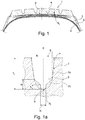
- Fig. 1 are of the usual components of a commercial vehicle tire, a tread 1, a radially located within the tread 1, multilayer, in the shown Four-layer embodiment, belt dressing 2, sections of a carcass insert 3 and an airtight inner layer 4, as well as the axially outer end sections of side walls 5 are shown.
- the bead areas with bead cores, core profiles and further reinforcement layers, optionally provided in the bead areas, are not shown and can be designed in a known manner.
- the tread 1 is provided with four circumferential grooves 6 which run straight in plan view ( Fig. 1b ).
- the circumferential grooves 6 can, however, also run in a zigzag or undulating manner or have sections running in a zigzag or undulating manner.
- each circumferential groove 6 on the tread periphery has a width B 1 in the axial direction and is designed in the radial direction to the intended profile depth T 1 .
- the width B 1 of the circumferential groove 6 is in particular 6.0 mm to 25.0 mm and the tread depth T 1 is usually 9.0 mm to 26.0 mm.
- the circumferential groove 6 is designed symmetrically with respect to a central plane E, which is spanned by the radial direction and the circumferential direction.
- the circumferential groove 6 has two mutually opposite groove walls 7 and a groove 8 which runs between the groove walls 7 and at the same time through the deepest point P 1 of the circumferential groove 6.
- the groove walls 7, viewed in cross-section, are each composed of a flat, radially outer flank surface 7a running to the tread periphery and a radially inner sloping surface 7b running to the groove base groove 8 and falling towards it.
- Each radially outer flank surface 7a, viewed in cross section, extends to the radial direction at an angle ⁇ of 0 ° to 15 °, and can therefore also run in the radial direction.
- the inclined surfaces 7b close to the radially inner ends of the flank surfaces at a distance a 1 determined in the radial direction from the level of the deepest point P 1 of up to 60%, in particular from 20% to 40%, of the depth T 1 7a.
- the inclined surfaces 7b, viewed in cross section run to the radial direction at an angle ⁇ of 30 ° to less than 90 °, in particular up to 60 °, and preferably from 40 ° to 50 °.
- the groove base groove 8 viewed in cross section, is U-shaped and has a width b 1 of at least 3.0 mm and at most 40% of the width B 1 of the circumferential groove 6 between its radially outer ends in the axial direction, the width b 1 is preferably 20% to 30% of the width B 1 of the circumferential groove 6. Furthermore, the groove base groove 8 has a depth t 1 of at least 0.3 mm and at most 90% of the mentioned distance a 1 in the radial direction, the depth t 1 in particular 30% to 70%, preferably 45% to 55%, of the distance a is 1 .
- the width b 1 of the groove base groove 8 is constant over the extent of the groove base groove 8, whereby a constant width is to be understood as one which, due to production, can vary in such a way that it is up to 3% larger at the actually widest point of the groove base groove 8 than the actual width at the narrowest point of the groove base groove 8.
- the circumferential groove 6 is preferably designed such that the tread 1 has a sub-profile thickness S 1 (radial profile) between the lowest point P 1 of the circumferential groove 6 and the belt assembly 2. Fig. 1 ) from 1.0 mm to 5.0 mm.
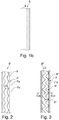
- FIGS. 2 and 3 each show a schematic top view of a section of a circumferential groove 6 ′ or 6 ′′, which variants of the circumferential groove 6 are.
- the two radially inner inclined surfaces 7'b have a continuously repeating increase and decrease in their width determined in cross section over their extension.
- the groove base groove 8 ' has at its radially outer end a constant width b 1 ', which is at least 3.0 mm and at most 40% of the width of the circumferential groove 6 'on the tread periphery.
- the width b 1 of the groove base groove 8 ′ is 20% to 30% of the width of the circumferential groove 6 ′ on the tread periphery.
- the circumferential groove 6 "shown has a zigzag groove basic groove 8" in plan view, which extends between a plurality of triangular projections 9 "in plan view.
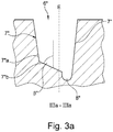
- the projections 9" extend to the central plane E of the circumferential groove 6 "and are bounded in the radial direction by inclined surfaces 7 "b of the groove walls 7", the inclined surfaces 7 "b, viewed in cross section, to the radial direction at an angle ⁇ " ( Fig. 3a ) from 30 ° to less than 90 °, in particular up to 60 °, and preferably from 40 ° to 50 °.
- the projections 9" are formed alternately on the groove walls 7 "within the circumferential groove 6", the projections 9 "on one groove wall 7” and the projections 9 “on the other groove wall 7 “are offset in the circumferential direction.
- the groove walls 7 ′′ In the area of the inclined surfaces 7 ′′ b, the groove walls 7 ′′ have flank surfaces 7 ′′ a running to the tread peripheral ( Fig. 3a ).
- the groove base groove 8 with the “outside tips” of its zigzag shape extends to the groove walls 7 "( Fig. 3a ).
- the groove base groove 8 " has a constant width b 1 " over its entire extent, which is at least 3.0 mm and at most 40% of the width of the circumferential groove 6 "at the tread periphery.
- Grooves designed according to the invention are main grooves of a tread, which include, for example, circumferential grooves and, in particular, V-shaped oblique grooves running across the width of the tread.
- An inclined groove is understood to mean a groove which extends at least over the majority of its extent at an angle deviating from the axial direction by more than 45 ° and - in contrast to the circumferential groove - does not run in the circumferential direction or at most one - in comparison to the total extension length. has a short circumferential section.
- oblique grooves extend to the axial direction at an angle of up to 75 °.
Landscapes
- Engineering & Computer Science (AREA)
- Mechanical Engineering (AREA)
- Tires In General (AREA)
Applications Claiming Priority (1)
| Application Number | Priority Date | Filing Date | Title |
|---|---|---|---|
| DE102018211946.5A DE102018211946A1 (de) | 2018-07-18 | 2018-07-18 | Fahrzeugluftreifen |
Publications (2)
| Publication Number | Publication Date |
|---|---|
| EP3597449A1 true EP3597449A1 (fr) | 2020-01-22 |
| EP3597449B1 EP3597449B1 (fr) | 2021-03-24 |
Family
ID=66821038
Family Applications (1)
| Application Number | Title | Priority Date | Filing Date |
|---|---|---|---|
| EP19179330.6A Active EP3597449B1 (fr) | 2018-07-18 | 2019-06-11 | Pneumatiques de véhicule |
Country Status (2)
| Country | Link |
|---|---|
| EP (1) | EP3597449B1 (fr) |
| DE (1) | DE102018211946A1 (fr) |
Cited By (2)
| Publication number | Priority date | Publication date | Assignee | Title |
|---|---|---|---|---|
| EP3978274A1 (fr) * | 2020-10-01 | 2022-04-06 | Continental Reifen Deutschland GmbH | Pneumatique de véhicule utilitaire |
| WO2025252515A1 (fr) * | 2024-06-04 | 2025-12-11 | Continental Reifen Deutschland Gmbh | Pneu de véhicule |
Families Citing this family (1)
| Publication number | Priority date | Publication date | Assignee | Title |
|---|---|---|---|---|
| DE102021205282A1 (de) * | 2021-05-25 | 2022-12-01 | Continental Reifen Deutschland Gmbh | Fahrzeugluftreifen mit einer Bandage |
Citations (7)
| Publication number | Priority date | Publication date | Assignee | Title |
|---|---|---|---|---|
| DE2951444A1 (de) * | 1978-12-22 | 1980-07-10 | Pirelli | Fahrzeugreifen |
| US4703788A (en) * | 1985-09-17 | 1987-11-03 | Sumitomo Rubber Industries, Ltd. | Tire tread with zig-zag grooves with projections in groove |
| DE102007016930A1 (de) | 2007-04-05 | 2008-10-09 | Continental Aktiengesellschaft | Fahrzeugluftreifen |
| EP2465705A1 (fr) * | 2009-09-07 | 2012-06-20 | Bridgestone Corporation | Bandage pneumatique |
| EP2567832A1 (fr) | 2010-05-07 | 2013-03-13 | Bridgestone Corporation | Pneu |
| TW201343428A (zh) * | 2012-04-24 | 2013-11-01 | Cheng Shin Rubber Ind Co Ltd | 多重不對稱溝壁之輪胎胎紋結構 |
| WO2016003433A1 (fr) | 2014-06-30 | 2016-01-07 | Compagnie Generale Des Etablissements Michelin | Arrête de rainure pour réduire l'épaisseur de sous-chape |
-
2018
- 2018-07-18 DE DE102018211946.5A patent/DE102018211946A1/de not_active Withdrawn
-
2019
- 2019-06-11 EP EP19179330.6A patent/EP3597449B1/fr active Active
Patent Citations (7)
| Publication number | Priority date | Publication date | Assignee | Title |
|---|---|---|---|---|
| DE2951444A1 (de) * | 1978-12-22 | 1980-07-10 | Pirelli | Fahrzeugreifen |
| US4703788A (en) * | 1985-09-17 | 1987-11-03 | Sumitomo Rubber Industries, Ltd. | Tire tread with zig-zag grooves with projections in groove |
| DE102007016930A1 (de) | 2007-04-05 | 2008-10-09 | Continental Aktiengesellschaft | Fahrzeugluftreifen |
| EP2465705A1 (fr) * | 2009-09-07 | 2012-06-20 | Bridgestone Corporation | Bandage pneumatique |
| EP2567832A1 (fr) | 2010-05-07 | 2013-03-13 | Bridgestone Corporation | Pneu |
| TW201343428A (zh) * | 2012-04-24 | 2013-11-01 | Cheng Shin Rubber Ind Co Ltd | 多重不對稱溝壁之輪胎胎紋結構 |
| WO2016003433A1 (fr) | 2014-06-30 | 2016-01-07 | Compagnie Generale Des Etablissements Michelin | Arrête de rainure pour réduire l'épaisseur de sous-chape |
Cited By (2)
| Publication number | Priority date | Publication date | Assignee | Title |
|---|---|---|---|---|
| EP3978274A1 (fr) * | 2020-10-01 | 2022-04-06 | Continental Reifen Deutschland GmbH | Pneumatique de véhicule utilitaire |
| WO2025252515A1 (fr) * | 2024-06-04 | 2025-12-11 | Continental Reifen Deutschland Gmbh | Pneu de véhicule |
Also Published As
| Publication number | Publication date |
|---|---|
| EP3597449B1 (fr) | 2021-03-24 |
| DE102018211946A1 (de) | 2020-01-23 |
Similar Documents
| Publication | Publication Date | Title |
|---|---|---|
| EP2892736B1 (fr) | Pneumatique de véhicule | |
| EP3589501A1 (fr) | Pneumatique de véhicule | |
| EP3256334B1 (fr) | Pneumatique de véhicule | |
| DE102015225939A1 (de) | Fahrzeugluftreifen | |
| EP3421264B1 (fr) | Pneumatique de véhicule | |
| EP3009275B1 (fr) | Pneumatiques de vehicule | |
| EP3597449B1 (fr) | Pneumatiques de véhicule | |
| DE102018208349A1 (de) | Fahrzeugluftreifen | |
| EP3256335B1 (fr) | Pneumatique de véhicule | |
| EP3009276B1 (fr) | Pneumatique de vehicule | |
| WO2018059759A1 (fr) | Pneumatique de véhicule | |
| EP3805019B1 (fr) | Pneumatique de véhicule | |
| DE102019206654A1 (de) | Fahrzeugluftreifen | |
| EP3789213B1 (fr) | Pneumatique de véhicule | |
| EP3560735B1 (fr) | Pneu de véhicule utilitaire | |
| EP2138327A1 (fr) | Bande de roulement por pneumatique | |
| DE102020208125A1 (de) | Fahrzeugluftreifen | |
| EP2138329A1 (fr) | Bande de roulement pour pneumatique | |
| DE102020205836A1 (de) | Fahrzeugluftreifen | |
| DE102020204072A1 (de) | Fahrzeugluftreifen | |
| EP3310592B1 (fr) | Pneumatique de véhicule | |
| EP4514632A1 (fr) | Pneu de véhicule | |
| EP3160771A1 (fr) | Pneumatique de véhicule | |
| EP3750722A1 (fr) | Pneumatique de véhicule | |
| EP3753753A1 (fr) | Pneumatique de véhicule |
Legal Events
| Date | Code | Title | Description |
|---|---|---|---|
| PUAI | Public reference made under article 153(3) epc to a published international application that has entered the european phase |
Free format text: ORIGINAL CODE: 0009012 |
|
| STAA | Information on the status of an ep patent application or granted ep patent |
Free format text: STATUS: THE APPLICATION HAS BEEN PUBLISHED |
|
| AK | Designated contracting states |
Kind code of ref document: A1 Designated state(s): AL AT BE BG CH CY CZ DE DK EE ES FI FR GB GR HR HU IE IS IT LI LT LU LV MC MK MT NL NO PL PT RO RS SE SI SK SM TR |
|
| AX | Request for extension of the european patent |
Extension state: BA ME |
|
| STAA | Information on the status of an ep patent application or granted ep patent |
Free format text: STATUS: REQUEST FOR EXAMINATION WAS MADE |
|
| 17P | Request for examination filed |
Effective date: 20200722 |
|
| RBV | Designated contracting states (corrected) |
Designated state(s): AL AT BE BG CH CY CZ DE DK EE ES FI FR GB GR HR HU IE IS IT LI LT LU LV MC MK MT NL NO PL PT RO RS SE SI SK SM TR |
|
| GRAP | Despatch of communication of intention to grant a patent |
Free format text: ORIGINAL CODE: EPIDOSNIGR1 |
|
| STAA | Information on the status of an ep patent application or granted ep patent |
Free format text: STATUS: GRANT OF PATENT IS INTENDED |
|
| RAP1 | Party data changed (applicant data changed or rights of an application transferred) |
Owner name: CONTINENTAL REIFEN DEUTSCHLAND GMBH |
|
| INTG | Intention to grant announced |
Effective date: 20201207 |
|
| GRAS | Grant fee paid |
Free format text: ORIGINAL CODE: EPIDOSNIGR3 |
|
| GRAA | (expected) grant |
Free format text: ORIGINAL CODE: 0009210 |
|
| STAA | Information on the status of an ep patent application or granted ep patent |
Free format text: STATUS: THE PATENT HAS BEEN GRANTED |
|
| AK | Designated contracting states |
Kind code of ref document: B1 Designated state(s): AL AT BE BG CH CY CZ DE DK EE ES FI FR GB GR HR HU IE IS IT LI LT LU LV MC MK MT NL NO PL PT RO RS SE SI SK SM TR |
|
| REG | Reference to a national code |
Ref country code: GB Ref legal event code: FG4D Free format text: NOT ENGLISH |
|
| REG | Reference to a national code |
Ref country code: CH Ref legal event code: EP |
|
| REG | Reference to a national code |
Ref country code: IE Ref legal event code: FG4D Free format text: LANGUAGE OF EP DOCUMENT: GERMAN |
|
| REG | Reference to a national code |
Ref country code: DE Ref legal event code: R096 Ref document number: 502019001040 Country of ref document: DE Ref country code: AT Ref legal event code: REF Ref document number: 1374116 Country of ref document: AT Kind code of ref document: T Effective date: 20210415 |
|
| REG | Reference to a national code |
Ref country code: LT Ref legal event code: MG9D |
|
| PG25 | Lapsed in a contracting state [announced via postgrant information from national office to epo] |
Ref country code: HR Free format text: LAPSE BECAUSE OF FAILURE TO SUBMIT A TRANSLATION OF THE DESCRIPTION OR TO PAY THE FEE WITHIN THE PRESCRIBED TIME-LIMIT Effective date: 20210324 Ref country code: BG Free format text: LAPSE BECAUSE OF FAILURE TO SUBMIT A TRANSLATION OF THE DESCRIPTION OR TO PAY THE FEE WITHIN THE PRESCRIBED TIME-LIMIT Effective date: 20210624 Ref country code: FI Free format text: LAPSE BECAUSE OF FAILURE TO SUBMIT A TRANSLATION OF THE DESCRIPTION OR TO PAY THE FEE WITHIN THE PRESCRIBED TIME-LIMIT Effective date: 20210324 Ref country code: GR Free format text: LAPSE BECAUSE OF FAILURE TO SUBMIT A TRANSLATION OF THE DESCRIPTION OR TO PAY THE FEE WITHIN THE PRESCRIBED TIME-LIMIT Effective date: 20210625 Ref country code: NO Free format text: LAPSE BECAUSE OF FAILURE TO SUBMIT A TRANSLATION OF THE DESCRIPTION OR TO PAY THE FEE WITHIN THE PRESCRIBED TIME-LIMIT Effective date: 20210624 |
|
| PG25 | Lapsed in a contracting state [announced via postgrant information from national office to epo] |
Ref country code: LV Free format text: LAPSE BECAUSE OF FAILURE TO SUBMIT A TRANSLATION OF THE DESCRIPTION OR TO PAY THE FEE WITHIN THE PRESCRIBED TIME-LIMIT Effective date: 20210324 Ref country code: RS Free format text: LAPSE BECAUSE OF FAILURE TO SUBMIT A TRANSLATION OF THE DESCRIPTION OR TO PAY THE FEE WITHIN THE PRESCRIBED TIME-LIMIT Effective date: 20210324 Ref country code: SE Free format text: LAPSE BECAUSE OF FAILURE TO SUBMIT A TRANSLATION OF THE DESCRIPTION OR TO PAY THE FEE WITHIN THE PRESCRIBED TIME-LIMIT Effective date: 20210324 |
|
| REG | Reference to a national code |
Ref country code: NL Ref legal event code: MP Effective date: 20210324 |
|
| PG25 | Lapsed in a contracting state [announced via postgrant information from national office to epo] |
Ref country code: NL Free format text: LAPSE BECAUSE OF FAILURE TO SUBMIT A TRANSLATION OF THE DESCRIPTION OR TO PAY THE FEE WITHIN THE PRESCRIBED TIME-LIMIT Effective date: 20210324 |
|
| PG25 | Lapsed in a contracting state [announced via postgrant information from national office to epo] |
Ref country code: SM Free format text: LAPSE BECAUSE OF FAILURE TO SUBMIT A TRANSLATION OF THE DESCRIPTION OR TO PAY THE FEE WITHIN THE PRESCRIBED TIME-LIMIT Effective date: 20210324 Ref country code: LT Free format text: LAPSE BECAUSE OF FAILURE TO SUBMIT A TRANSLATION OF THE DESCRIPTION OR TO PAY THE FEE WITHIN THE PRESCRIBED TIME-LIMIT Effective date: 20210324 Ref country code: CZ Free format text: LAPSE BECAUSE OF FAILURE TO SUBMIT A TRANSLATION OF THE DESCRIPTION OR TO PAY THE FEE WITHIN THE PRESCRIBED TIME-LIMIT Effective date: 20210324 Ref country code: EE Free format text: LAPSE BECAUSE OF FAILURE TO SUBMIT A TRANSLATION OF THE DESCRIPTION OR TO PAY THE FEE WITHIN THE PRESCRIBED TIME-LIMIT Effective date: 20210324 |
|
| PG25 | Lapsed in a contracting state [announced via postgrant information from national office to epo] |
Ref country code: PL Free format text: LAPSE BECAUSE OF FAILURE TO SUBMIT A TRANSLATION OF THE DESCRIPTION OR TO PAY THE FEE WITHIN THE PRESCRIBED TIME-LIMIT Effective date: 20210324 Ref country code: PT Free format text: LAPSE BECAUSE OF FAILURE TO SUBMIT A TRANSLATION OF THE DESCRIPTION OR TO PAY THE FEE WITHIN THE PRESCRIBED TIME-LIMIT Effective date: 20210726 Ref country code: RO Free format text: LAPSE BECAUSE OF FAILURE TO SUBMIT A TRANSLATION OF THE DESCRIPTION OR TO PAY THE FEE WITHIN THE PRESCRIBED TIME-LIMIT Effective date: 20210324 Ref country code: SK Free format text: LAPSE BECAUSE OF FAILURE TO SUBMIT A TRANSLATION OF THE DESCRIPTION OR TO PAY THE FEE WITHIN THE PRESCRIBED TIME-LIMIT Effective date: 20210324 Ref country code: IS Free format text: LAPSE BECAUSE OF FAILURE TO SUBMIT A TRANSLATION OF THE DESCRIPTION OR TO PAY THE FEE WITHIN THE PRESCRIBED TIME-LIMIT Effective date: 20210724 |
|
| REG | Reference to a national code |
Ref country code: DE Ref legal event code: R097 Ref document number: 502019001040 Country of ref document: DE |
|
| PG25 | Lapsed in a contracting state [announced via postgrant information from national office to epo] |
Ref country code: ES Free format text: LAPSE BECAUSE OF FAILURE TO SUBMIT A TRANSLATION OF THE DESCRIPTION OR TO PAY THE FEE WITHIN THE PRESCRIBED TIME-LIMIT Effective date: 20210324 Ref country code: DK Free format text: LAPSE BECAUSE OF FAILURE TO SUBMIT A TRANSLATION OF THE DESCRIPTION OR TO PAY THE FEE WITHIN THE PRESCRIBED TIME-LIMIT Effective date: 20210324 Ref country code: AL Free format text: LAPSE BECAUSE OF FAILURE TO SUBMIT A TRANSLATION OF THE DESCRIPTION OR TO PAY THE FEE WITHIN THE PRESCRIBED TIME-LIMIT Effective date: 20210324 Ref country code: MC Free format text: LAPSE BECAUSE OF FAILURE TO SUBMIT A TRANSLATION OF THE DESCRIPTION OR TO PAY THE FEE WITHIN THE PRESCRIBED TIME-LIMIT Effective date: 20210324 |
|
| PLBE | No opposition filed within time limit |
Free format text: ORIGINAL CODE: 0009261 |
|
| STAA | Information on the status of an ep patent application or granted ep patent |
Free format text: STATUS: NO OPPOSITION FILED WITHIN TIME LIMIT |
|
| PG25 | Lapsed in a contracting state [announced via postgrant information from national office to epo] |
Ref country code: SI Free format text: LAPSE BECAUSE OF FAILURE TO SUBMIT A TRANSLATION OF THE DESCRIPTION OR TO PAY THE FEE WITHIN THE PRESCRIBED TIME-LIMIT Effective date: 20210324 |
|
| 26N | No opposition filed |
Effective date: 20220104 |
|
| REG | Reference to a national code |
Ref country code: BE Ref legal event code: MM Effective date: 20210630 |
|
| PG25 | Lapsed in a contracting state [announced via postgrant information from national office to epo] |
Ref country code: LU Free format text: LAPSE BECAUSE OF NON-PAYMENT OF DUE FEES Effective date: 20210611 |
|
| PG25 | Lapsed in a contracting state [announced via postgrant information from national office to epo] |
Ref country code: IE Free format text: LAPSE BECAUSE OF NON-PAYMENT OF DUE FEES Effective date: 20210611 |
|
| PG25 | Lapsed in a contracting state [announced via postgrant information from national office to epo] |
Ref country code: IS Free format text: LAPSE BECAUSE OF FAILURE TO SUBMIT A TRANSLATION OF THE DESCRIPTION OR TO PAY THE FEE WITHIN THE PRESCRIBED TIME-LIMIT Effective date: 20210724 |
|
| PG25 | Lapsed in a contracting state [announced via postgrant information from national office to epo] |
Ref country code: BE Free format text: LAPSE BECAUSE OF NON-PAYMENT OF DUE FEES Effective date: 20210630 |
|
| PG25 | Lapsed in a contracting state [announced via postgrant information from national office to epo] |
Ref country code: IT Free format text: LAPSE BECAUSE OF FAILURE TO SUBMIT A TRANSLATION OF THE DESCRIPTION OR TO PAY THE FEE WITHIN THE PRESCRIBED TIME-LIMIT Effective date: 20210324 |
|
| REG | Reference to a national code |
Ref country code: CH Ref legal event code: PL |
|
| PG25 | Lapsed in a contracting state [announced via postgrant information from national office to epo] |
Ref country code: LI Free format text: LAPSE BECAUSE OF NON-PAYMENT OF DUE FEES Effective date: 20220630 Ref country code: CH Free format text: LAPSE BECAUSE OF NON-PAYMENT OF DUE FEES Effective date: 20220630 |
|
| PG25 | Lapsed in a contracting state [announced via postgrant information from national office to epo] |
Ref country code: CY Free format text: LAPSE BECAUSE OF FAILURE TO SUBMIT A TRANSLATION OF THE DESCRIPTION OR TO PAY THE FEE WITHIN THE PRESCRIBED TIME-LIMIT Effective date: 20210324 |
|
| PG25 | Lapsed in a contracting state [announced via postgrant information from national office to epo] |
Ref country code: HU Free format text: LAPSE BECAUSE OF FAILURE TO SUBMIT A TRANSLATION OF THE DESCRIPTION OR TO PAY THE FEE WITHIN THE PRESCRIBED TIME-LIMIT; INVALID AB INITIO Effective date: 20190611 |
|
| REG | Reference to a national code |
Ref country code: DE Ref legal event code: R081 Ref document number: 502019001040 Country of ref document: DE Owner name: CONTINENTAL REIFEN DEUTSCHLAND GMBH, DE Free format text: FORMER OWNER: CONTINENTAL REIFEN DEUTSCHLAND GMBH, 30165 HANNOVER, DE |
|
| PG25 | Lapsed in a contracting state [announced via postgrant information from national office to epo] |
Ref country code: MK Free format text: LAPSE BECAUSE OF FAILURE TO SUBMIT A TRANSLATION OF THE DESCRIPTION OR TO PAY THE FEE WITHIN THE PRESCRIBED TIME-LIMIT Effective date: 20210324 |
|
| PGFP | Annual fee paid to national office [announced via postgrant information from national office to epo] |
Ref country code: GB Payment date: 20240621 Year of fee payment: 6 |
|
| PG25 | Lapsed in a contracting state [announced via postgrant information from national office to epo] |
Ref country code: MT Free format text: LAPSE BECAUSE OF FAILURE TO SUBMIT A TRANSLATION OF THE DESCRIPTION OR TO PAY THE FEE WITHIN THE PRESCRIBED TIME-LIMIT Effective date: 20210324 |
|
| PGFP | Annual fee paid to national office [announced via postgrant information from national office to epo] |
Ref country code: DE Payment date: 20250630 Year of fee payment: 7 |
|
| PGFP | Annual fee paid to national office [announced via postgrant information from national office to epo] |
Ref country code: FR Payment date: 20250626 Year of fee payment: 7 |
|
| REG | Reference to a national code |
Ref country code: AT Ref legal event code: MM01 Ref document number: 1374116 Country of ref document: AT Kind code of ref document: T Effective date: 20240611 |
|
| PG25 | Lapsed in a contracting state [announced via postgrant information from national office to epo] |
Ref country code: AT Free format text: LAPSE BECAUSE OF NON-PAYMENT OF DUE FEES Effective date: 20240611 |
|
| PG25 | Lapsed in a contracting state [announced via postgrant information from national office to epo] |
Ref country code: TR Free format text: LAPSE BECAUSE OF FAILURE TO SUBMIT A TRANSLATION OF THE DESCRIPTION OR TO PAY THE FEE WITHIN THE PRESCRIBED TIME-LIMIT Effective date: 20210324 |
|
| GBPC | Gb: european patent ceased through non-payment of renewal fee |
Effective date: 20250611 |
|
| PG25 | Lapsed in a contracting state [announced via postgrant information from national office to epo] |
Ref country code: GB Free format text: LAPSE BECAUSE OF NON-PAYMENT OF DUE FEES Effective date: 20250611 |
|
| PGFP | Annual fee paid to national office [announced via postgrant information from national office to epo] |
Ref country code: AT Payment date: 20260410 Year of fee payment: 5 |